US949910A - Journal-box. - Google Patents
Journal-box. Download PDFInfo
- Publication number
- US949910A US949910A US46687708A US1908466877A US949910A US 949910 A US949910 A US 949910A US 46687708 A US46687708 A US 46687708A US 1908466877 A US1908466877 A US 1908466877A US 949910 A US949910 A US 949910A
- Authority
- US
- United States
- Prior art keywords
- box
- lining
- sections
- parts
- journal
- Prior art date
- Legal status (The legal status is an assumption and is not a legal conclusion. Google has not performed a legal analysis and makes no representation as to the accuracy of the status listed.)
- Expired - Lifetime
Links
- 229910000897 Babbitt (metal) Inorganic materials 0.000 description 1
- 229910001369 Brass Inorganic materials 0.000 description 1
- 208000002193 Pain Diseases 0.000 description 1
- 239000010951 brass Substances 0.000 description 1
- 101150002095 capB gene Proteins 0.000 description 1
- 238000005266 casting Methods 0.000 description 1
- 235000021183 entrée Nutrition 0.000 description 1
- 230000006870 function Effects 0.000 description 1
- 239000000463 material Substances 0.000 description 1
- 239000002184 metal Substances 0.000 description 1
- 238000000034 method Methods 0.000 description 1
- 238000012986 modification Methods 0.000 description 1
- 230000004048 modification Effects 0.000 description 1
- 230000002093 peripheral effect Effects 0.000 description 1
- 239000007787 solid Substances 0.000 description 1
Images
Classifications
-
- F—MECHANICAL ENGINEERING; LIGHTING; HEATING; WEAPONS; BLASTING
- F16—ENGINEERING ELEMENTS AND UNITS; GENERAL MEASURES FOR PRODUCING AND MAINTAINING EFFECTIVE FUNCTIONING OF MACHINES OR INSTALLATIONS; THERMAL INSULATION IN GENERAL
- F16C—SHAFTS; FLEXIBLE SHAFTS; ELEMENTS OR CRANKSHAFT MECHANISMS; ROTARY BODIES OTHER THAN GEARING ELEMENTS; BEARINGS
- F16C33/00—Parts of bearings; Special methods for making bearings or parts thereof
- F16C33/02—Parts of sliding-contact bearings
- F16C33/04—Brasses; Bushes; Linings
- F16C33/06—Sliding surface mainly made of metal
- F16C33/08—Attachment of brasses, bushes or linings to the bearing housing
Definitions
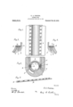
- FIG. 1 is-a plan view of one type of divided box showing the cap or top part removed.
- FIG. 2 is a cross section of the same showing the cap inplace. Figs.
- A represents the main portion of a journal-box having a capB, fitted into-it; this box is of the side flanged type, but my invention is equally applicable to an ordinary half box and cap as well as to-otherforms of journal boxes which are divided for the purpose of taking up wear.
- C is a lining forming the bearing for the journal, and is made preferably in two parts longitudinally, but if required can be made in as many parts as it is desirable to sep-v arate the box into.
- the material for-the linings may be brass, Babbitt metal or any suitable metal either cast to size or machined. I prefer that the parts of this lining project slightly beyond the division lines 5 of the box. as indicated. in Figs. 3 and 4, and clamping plates D are provided pressing against the edges of the lining sections, and secured to the adjacent parts of the box and cap (or boxsections) by means of screws 1.
- the clamping plates may lie in a rabbet formed in the edges of lining sections, so that practically the entire inner surface of the lining can be utilized for hearing purposes.
- the screws 1, and clamps D force the lining sections against the interior periphery of the box, so as to produce rigid contact and'con sequently a solid backlng for the lining. This is an important result especially for journals running at a high speed, where vibration must be eliminated.
- I provide a wedge-like or beveled lip 4, on oneedge of the clamping plates D, which fits into a corresponding as circular in section an groove in the edge of the lining sections G. hen therefore the plate D is forced down by the screws 1, the action of the beveled lip dis to wedge or thrust the lining radially, or nearly so, into the bore or recess 0 the box, and thus produce rigid contact around the peripheral surfaces.
- Fig. 4 a compressible or elastic strip is shown under the clamping plate, thus parclamping plates to perform their function
- journal box comprising separate parts each haying ledges or supporting clamping plates, lining sections in the parts of the journal box, clamping plates supported on said ledges and bearing on proximate edges 01": the lining sections, there being a lip at an edge of eachclamping plate on the ledge side thereof whereby the body of each plate stands away from its ledge and means for securing the clamping plates to the. ledges and firmly pressing the lining sections against the inner surface of the parts of the box notwithstanding variations in the sizes of such parts.
- a journal box comprising separable parts having plate-supporting ledges, de tachable lining sections in the parts of the box, clamping plates on the ledges, the clamping plates each having a projecting lip, or lips, on the side facing its ledge, one edge of each plate normally bearing on an edge of a lining section, the bodies of said plates adjacent such edges being separated from the supporting edges to provide. adjustment against Var tions in lining sections and boxes, and p ate-clamping screws.
- journal box comprising separate parts, removable linin s made in sections longitudinally, edges of said sections having bevel grooves, clamping plates having beveled lips fitting into the corresponding grooves in the edges of the lining sections, means for securing said clamping plates to the parts of the box, whereby the sections are forced radially or approximately so, against the inner periphery of the box, for the purposes set forth.
- journal box comprising separate parts, removable lining sections with their longitudinal edges projecting slightly beyond the division lines of the box, clamping plates for securing said linings in their respective recesses, means for securing said clamping plates to the parts of the box, there being a clearance under the clamping plates, whereby pressure is exerted mainl on the lining sections, for the purposes set fortln 6.
- a journal box comprising a plurality of separate parts, a lining for each part of the box, adjustable clamping plates with beveled parts bearing on the lining sections in approximately a radial direction, the edges of the lining in each part of the box having surfaces cooperating with said beveled parts of the clamping plates, and means for securing such plates to their respective parts of the box.
Landscapes
- Engineering & Computer Science (AREA)
- General Engineering & Computer Science (AREA)
- Mechanical Engineering (AREA)
- Clamps And Clips (AREA)
- Connection Of Plates (AREA)
Description
Patented Feb. 22, 1910.
avwenl oz Wmm'm am. am.
entree smarts rem @FFEQE.
irmAM A. PERKINS, or. ROCHESTER, New vohx,
co, or ROCHESTER, NEW YORK, A CORPORATION or WORKING MACHINERY PENNSYLVANIA.
Specification of Letters Patent.
As'sroNon 'ro AMERICAN -woon ioUnNAL-Box.
Patented Feb. 22, rate.
Application filed December 10, 1908. Serial No. 466,877.
erably made in two or more longitudinal.
sections, into the bore or recess of the box. In the drawing F gure 1 is-a plan view of one type of divided box showing the cap or top part removed. :Fig. 2 is a cross section of the same showing the cap inplace. Figs.
3,4 and 5 show details and modifications.
A represents the main portion of a journal-box having a capB, fitted into-it; this box is of the side flanged type, but my invention is equally applicable to an ordinary half box and cap as well as to-otherforms of journal boxes which are divided for the purpose of taking up wear. i
C is a lining forming the bearing for the journal, and is made preferably in two parts longitudinally, but if required can be made in as many parts as it is desirable to sep-v arate the box into. The material for-the linings may be brass, Babbitt metal or any suitable metal either cast to size or machined. I prefer that the parts of this lining project slightly beyond the division lines 5 of the box. as indicated. in Figs. 3 and 4, and clamping plates D are provided pressing against the edges of the lining sections, and secured to the adjacent parts of the box and cap (or boxsections) by means of screws 1. It will'be seen that the clamping plates may lie in a rabbet formed in the edges of lining sections, so that practically the entire inner surface of the lining can be utilized for hearing purposes. The screws 1, and clamps D, force the lining sections against the interior periphery of the box, so as to produce rigid contact and'con sequently a solid backlng for the lining. This is an important result especially for journals running at a high speed, where vibration must be eliminated.
In order to further insure such rigid contact of the box, I provide a wedge-like or beveled lip 4, on oneedge of the clamping plates D, which fits into a corresponding as circular in section an groove in the edge of the lining sections G. hen therefore the plate D is forced down by the screws 1, the action of the beveled lip dis to wedge or thrust the lining radially, or nearly so, into the bore or recess 0 the box, and thus produce rigid contact around the peripheral surfaces.
It will be observed that by means of the projection of the edges of the lining beyond the division lines of the box, I secure a clearance between the plates D, and the ledge 5,-01' parting line of the'box, as indicated in Figs. 3 and 4. This is for the purpose of insuring clamping pressure on the lining sections, and I have indicated in Fig. 2 that the plates D may be pitched slightly away from a radial line so as to have a bearing on the parting ledge 5 of the box at-one edge, and on the lining section at the opposite edge. Other means of utilizing this clearance are shown in Fig. 3 Where a slight bearing lip 3 is provided, forming a fulcrum upon which the clamping plate is supported along one edge while the other edge is forced against thelining section bythe screws.
In Fig. 4 a compressible or elastic strip is shown under the clamping plate, thus parclamping plates to perform their function,
but in practice this clearance is desirable for the purpose of providing against slight and insuring the acinaccuracles of fitting tual contact of thelining and the box by the clamping pressure.
I have shown the linin space in the box' the lining asannulan, because boring the box and turning the lining on casting it in an annular mold made in sections to correspond withthe dimensions of'the box, is apparently the most practical method of producing the complete ox; but other forms of lining space, either machined or left rough from the mold or forge, or of polygonal or square cross-section, may be used in connection with my invention, the lining sections in such cases being cast into the box or otherwise roughly fitted.
. interior of the box notwithstanding variations in the lining sections or in the box.
2. In a journal box comprising separate parts each haying ledges or supporting clamping plates, lining sections in the parts of the journal box, clamping plates supported on said ledges and bearing on proximate edges 01": the lining sections, there being a lip at an edge of eachclamping plate on the ledge side thereof whereby the body of each plate stands away from its ledge and means for securing the clamping plates to the. ledges and firmly pressing the lining sections against the inner surface of the parts of the box notwithstanding variations in the sizes of such parts.
3. A journal box comprising separable parts having plate-supporting ledges, de tachable lining sections in the parts of the box, clamping plates on the ledges, the clamping plates each having a projecting lip, or lips, on the side facing its ledge, one edge of each plate normally bearing on an edge of a lining section, the bodies of said plates adjacent such edges being separated from the supporting edges to provide. adjustment against Var tions in lining sections and boxes, and p ate-clamping screws.
4. In a journal box comprising separate parts, removable linin s made in sections longitudinally, edges of said sections having bevel grooves, clamping plates having beveled lips fitting into the corresponding grooves in the edges of the lining sections, means for securing said clamping plates to the parts of the box, whereby the sections are forced radially or approximately so, against the inner periphery of the box, for the purposes set forth.
5. In a journal box comprising separate parts, removable lining sections with their longitudinal edges projecting slightly beyond the division lines of the box, clamping plates for securing said linings in their respective recesses, means for securing said clamping plates to the parts of the box, there being a clearance under the clamping plates, whereby pressure is exerted mainl on the lining sections, for the purposes set fortln 6. A journal box comprising a plurality of separate parts, a lining for each part of the box, adjustable clamping plates with beveled parts bearing on the lining sections in approximately a radial direction, the edges of the lining in each part of the box having surfaces cooperating with said beveled parts of the clamping plates, and means for securing such plates to their respective parts of the box.
In testimony whereof I have signed my name to this specification in the presence of two subscribing witnesses.
IIIRAM A. PERKINS.
v Witnesses G. C. SOUTHARD, R. J. MCKELVEY.
Priority Applications (1)
| Application Number | Priority Date | Filing Date | Title |
|---|---|---|---|
| US46687708A US949910A (en) | 1908-12-10 | 1908-12-10 | Journal-box. |
Applications Claiming Priority (1)
| Application Number | Priority Date | Filing Date | Title |
|---|---|---|---|
| US46687708A US949910A (en) | 1908-12-10 | 1908-12-10 | Journal-box. |
Publications (1)
| Publication Number | Publication Date |
|---|---|
| US949910A true US949910A (en) | 1910-02-22 |
Family
ID=3018324
Family Applications (1)
| Application Number | Title | Priority Date | Filing Date |
|---|---|---|---|
| US46687708A Expired - Lifetime US949910A (en) | 1908-12-10 | 1908-12-10 | Journal-box. |
Country Status (1)
| Country | Link |
|---|---|
| US (1) | US949910A (en) |
Cited By (4)
| Publication number | Priority date | Publication date | Assignee | Title |
|---|---|---|---|---|
| US6280091B1 (en) * | 1998-10-30 | 2001-08-28 | Dana Corporation | Bearings |
| US20080247692A1 (en) * | 2007-04-04 | 2008-10-09 | Pacific Bearing Company | Extrudable Polymer Bearing Insert |
| US20080247693A1 (en) * | 2007-04-04 | 2008-10-09 | Pacific Bearing Company | Snap-In Bearing Insert |
| US10087984B2 (en) | 2015-06-30 | 2018-10-02 | Saint-Gobain Performance Plastics Corporation | Plain bearing |
-
1908
- 1908-12-10 US US46687708A patent/US949910A/en not_active Expired - Lifetime
Cited By (5)
| Publication number | Priority date | Publication date | Assignee | Title |
|---|---|---|---|---|
| US6280091B1 (en) * | 1998-10-30 | 2001-08-28 | Dana Corporation | Bearings |
| US20080247692A1 (en) * | 2007-04-04 | 2008-10-09 | Pacific Bearing Company | Extrudable Polymer Bearing Insert |
| US20080247693A1 (en) * | 2007-04-04 | 2008-10-09 | Pacific Bearing Company | Snap-In Bearing Insert |
| US8376617B2 (en) * | 2007-04-04 | 2013-02-19 | Pacific Bearing Company | Snap-in bearing insert |
| US10087984B2 (en) | 2015-06-30 | 2018-10-02 | Saint-Gobain Performance Plastics Corporation | Plain bearing |
Similar Documents
| Publication | Publication Date | Title |
|---|---|---|
| US2912264A (en) | Journal bearings | |
| US420951A (en) | Anti-friction bearing | |
| US627985A (en) | Journal-bearing. | |
| US1121849A (en) | Bearing. | |
| US388933A (en) | Apparatus for lining journal-boxes | |
| US850399A (en) | Journal-bearing. | |
| US835546A (en) | Loose pulley. | |
| US149284A (en) | Improvement in journal-bearings for car-axles | |
| US675596A (en) | Journal-box and adjustable bearing therefor. | |
| US408633A (en) | Axle-box | |
| US50445A (en) | Improved journal-box | |
| US687205A (en) | Journal-bearing. | |
| US1100403A (en) | Lubricating journal-box. | |
| US1012662A (en) | Step-bearing. | |
| JP2026054857A (en) | Plummer block | |
| US1274529A (en) | Bearing. | |
| US803159A (en) | Journal-bearing. | |
| US762152A (en) | Car-axle box. | |
| US139287A (en) | Improvement in journal-boxes | |
| GB717815A (en) | Improvements in journal boxes for axles | |
| US309891A (en) | Interlocking journal-bearing | |
| US460409A (en) | Bearing | |
| GB191328710A (en) | Improvements in and relating to Machinery Brasses or Bearings. | |
| US354582A (en) | Chaeles talbot pobtee | |
| US40729A (en) | Improvement in journal-boxes for railroad-cars |