CROSS-REFERENCE TO RELATED APPLICATION
This application is a continuation-in-part of U.S. Ser. No. 14/325,928 filed Jul. 8, 2014; which claims the benefit of Korean Patent Application No. 10-2014-0048348, filed on Apr. 22, 2014, in the Korean Intellectual Property Office; and Korean Patent Application No. 10-2015-0034034, filed on Mar. 11, 2015, in the Korean Intellectual Property Office, the disclosures of which are incorporated herein in their entirety by reference.
BACKGROUND
1. Field
The present disclosure relates to a hybrid electronic sheet and a method for preparing the same.
2. Description of the Related Art
Researches on flexible high-performance materials and devices such as wearable computers, bendable displays, wearable biomedical electrodes and biosensors for health monitoring, human-robot interfaces, etc. are rapidly increasing nowadays. For such applications, development of a material which has excellent electrical property as well as superior mechanical property and to which biochemical or biological property can be further provided in addition to the electrical property, e.g., as in wearable biosensors, is of great importance. In addition, for realization of a high-performance device composed of various constituents on a flexible substrate, low contact resistance is required between the constituents and superior contact property with the flexible substrate is necessary.
Since carbon nanomaterials such as carbon nanotube, graphene, etc. have excellent electrical, mechanical and chemical properties, use of the materials as an electrode of flexible electronic devices, flexible bioelectrodes, sensors, flexible energy devices, etc. is actively studied recently.
For application of graphene or carbon nanotube to flexible devices, a process of transferring the graphene or carbon nanotube synthesized at high temperature without decrease in electrical property is essential. In addition, for effective operation of a high-performance device, effective electrical contact property between the carbon nanomaterial and other constituents of the device and resistance property on the flexible substrate are very important. Carbon nanotube is commonly used by depositing a film on a substrate, for example, by spin coating the carbon nanotube dispersed in an organic solvent or by forming a film through vacuum filtration and dissolving out the filter membrane chemically to obtain a carbon nanotube film. However, these methods are problematic in that the performance of the device is decreased or contact property with a flexible substrate is unsatisfactory due to an organic solvent or a dispersant remaining after chemical etching. Also, transfer onto a substrate with a complex shape is impossible because of large film thickness and patterning which is essential for realization of the device is difficult.
Graphene is used by growing the graphene on the surface of a metal such as copper by chemical vapor deposition (CVD) and transferring onto a desired substrate using an etching solution or by reducing chemically prepared graphene oxide through spin coating to obtain a reduced graphene oxide film. However, the CVD-grown graphene is disadvantageous in that use of an environmentally very harmful etching solution is necessary and effective surface area per unit area is very small because the graphene consists of a single or only a few layer(s). Further, because graphene is chemically stable, it is not easy to confer additional properties to the graphene. The reduced graphene oxide is disadvantageous in that electrical property is not excellent because a process of chemically reducing the graphene oxide which has been chemically oxidized is required.
When preparing a flexible electrode including a biomaterial such as a biosensor electrode, it is important to realize a high-performance flexible device without chemical etching. However, with the existing methods, it is difficult to realize a flexible device having superior electrical property wherein a biomaterial is nanohybridized.
SUMMARY
An aspect provides an electronic sheet including a graphitic material and a phage binding to the graphitic material, wherein a peptide is displayed on a coat protein of the phage or a fragment of the phage, and the binding occurs between the graphitic material and the peptide.
Another aspect provides an electrode or electronic device including the electronic sheet.
Still aspect provides a method of preparing a hybrid electronic sheet including: preparing a colloid material containing the graphitic material; adding the phage, which displays the peptide having a binding ability to the graphitic material on its coat protein or a fragment thereof, to a solution so as to prepare a phage solution; mixing the colloid material and the phage solution so as to prepare a mixture; and dialyzing the mixture using a membrane so as to form an electronic sheet in a solution.
An aspect provides an electronic sheet including a graphitic material and a phage binding to the graphitic material, in which the binding occurs between a peptide displayed on a coat protein of the phage or a fragment thereof and the graphitic material.
As used herein, the term “sheet” may refer to a material having a predetermined width and thickness, and for example, it is understood to include a film, a web, a membrane, or a complex structure thereof.
BRIEF DESCRIPTION OF THE DRAWINGS
These and/or other aspects will become apparent and more readily appreciated from the following description of the embodiments, taken in conjunction with the accompanying drawings in which:
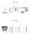
FIGS. 1A through 1D are schematic illustrations of an electrode including a hybrid electronic sheet according to an exemplary embodiment;
FIG. 2 is a schematic illustration of an electrode including the hybrid electronic sheet functionalized with a biochemical enzyme according to an exemplary embodiment;
FIG. 3A is a schematic illustration of a production process of the hybrid electronic sheet according to an exemplary embodiment;
FIG. 3B is a schematic illustration of a formation principle of the hybrid electronic sheet according to an exemplary embodiment;
FIG. 3C is a graph showing concentration polarization in the formation principle of the hybrid electronic sheet according to an exemplary embodiment;
FIG. 4A is an image showing formation of the hybrid electronic sheet according to an exemplary embodiment;
FIG. 4B is a graph showing the dependency of hybrid electronic sheet formation on the ionic strength of a dialysis solution according to an exemplary embodiment;
FIG. 5 is an image of a large-area freestanding hybrid electronic sheet according to an exemplary embodiment;
FIG. 6 is an image of a sample having only a single-walled carbon nanotube without a phage;
FIG. 7 is a scanning electron microscopic (SEM) image showing a nanostructure of a phage-bound hybrid electronic sheet according to an exemplary embodiment and a nanostructure of a non-phage bound electronic sheet;
FIG. 8A is an image of the hybrid electronic sheet according to an exemplary embodiment which is transferred onto a PES polymer substrate;
FIG. 8B is an image of the hybrid electronic sheet according to an exemplary embodiment which is transferred onto a plastic substrate with a complex shape;
FIG. 9 is a schematic illustration of a method of patterning a hybrid electronic sheet using a stencil mask according to an exemplary embodiment and an image of the patterned hybrid electronic sheet;
FIG. 10 is a graph showing a result of measuring contact angles to compare the change in hydrophilic property of the electronic sheet according to an exemplary embodiment depending on a molar ratio (SWNT:p8GB#1=4:1, 10:1, 20:1) of a single-walled carbon nanotube and a phage (p8GB#1) in the hybrid electronic sheet;
FIG. 11 is a graph showing electrochemical conductivity of the hybrid electronic sheet according to an exemplary embodiment;
FIG. 12 is an SEM image of an electronic device which is prepared by using the hybrid electronic sheet according to an exemplary embodiment;
FIG. 13 is a graph showing electrical conductivity of the electronic device which is prepared by using the hybrid electronic sheet according to an exemplary embodiment;
FIG. 14 is a graph showing electrochemical conductivity of the hybrid electronic sheet according to an exemplary embodiment;
FIG. 15A is a schematic illustration of a current biosensing of a hybrid electronic sheet, in which the hybrid electronic sheet is functionalized with an enzyme according to an exemplary embodiment; and
FIG. 15B is a graph showing selective current response of a biosensor to hydrogen peroxide, in which the biosensor includes the hybrid enzyme electronic sheet according to an exemplary embodiment.
DETAILED DESCRIPTION
Reference will now be made in detail to embodiments, examples of which are illustrated in the accompanying drawings, wherein like reference numerals refer to like elements throughout. In this regard, the present embodiments may have different forms and should not be construed as being limited to the descriptions set forth herein. Accordingly, the exemplary embodiments are merely described below, by referring to the figures, to explain aspects of the present description.
As used herein, the term “graphitic material” may refer to a material having a surface with hexagonal arrangement of carbon atoms, i.e., a graphitic surface, and may include any graphitic material having the graphitic surface, regardless of physical, chemical or structural properties. Examples thereof may include a graphene sheet, a highly ordered pyrolytic graphite (HOPG) sheet, a carbon nanotube such as a single-walled carbon nanotube, a double-walled carbon nanotube, and a multi-walled carbon nanotube, or fullerene. The graphitic material may be a metallic, semiconductive, or hybrid material. For example, the graphitic material may be a mixture of a graphene sheet and a single-walled carbon nanotube.
In an exemplary embodiment, if the graphene sheet is used as the graphitic material, a two-dimensional structure of the graphene sheet allows a large contact area between constituent materials, compared to a material of one-dimensional structure. Therefore, it is possible to realize a large hybrid electronic sheet.
In another specific embodiment, if a mixture of the graphene sheet and the single-walled carbon nanotube is used as the graphitic material, the problem that a high concentration is necessary only when the graphene sheet is used may be solved while providing the advantage of two-dimensional structure of the graphene sheet.
In still another specific embodiment, if the graphene sheet is mixed with the single-walled carbon nanotube, the size and thickness of the sheet become larger and, in this case, the effective area of a nanoelectrode per unit area becomes large.
The peptide binding to the graphitic material may be a material capable of binding to the graphitic material in a nondestructive manner. The peptide may be selected from peptide libraries, for example, by a phage display technique. Through the phage display technique, the peptide may be genetically linked to, inserted into, or substituted for the coat protein of the phage, resulting in display of the protein on the exterior of phage, in which the peptide may be encoded by genetic information in the virion. Vast numbers of variants of the protein may be selected and screened by the displayed protein and DNA encoding the same, this method is called “biopanning”. Briefly, biopanning is carried out by incubating the pool of phage-displayed variants with a target (e.g., graphitic material) that has been immobilized, washing away unbound phage, and eluting specifically bound phage by disrupting the binding interactions between the phage and the target. A portion of the eluted phage is set aside for DNA sequencing and peptide identification, and the remainder is amplified in vivo to prepare a sub-library for the next round. Then, this procedure is repeated.
The term “phage” or “bacteriophage” is used interchangeably, and may refer to a virus that infects bacteria and replicates within the bacteria. The phage or bacteriophage may be used to display a peptide which selectively or specifically binds to a graphitic material or volatile organic compound. The phage may be genetically engineered to display the peptide capable of binding to the graphitic material on a coat protein of the phage or a fragment thereof. As used herein, the term “genetic engineering” or “genetically engineered” means introduction of one or more genetic modifications into the phage in order to display the peptide capable of binding to the graphitic material on the coat protein of the phage or the fragment thereof, or a phage prepared thereby. The genetic modifications include introduction of a foreign gene encoding the peptide. The phage may be a filamentous phage, for example, M13 phage, F1 phage, Fd phage, If1 phage, Ike phage, Zj/Z phage, Ff phage, Xf phage, Pf1 phage, or Pf3 phage.
As used herein, the term “phage display” or “phage with a peptide displayed thereon” may refer to a display of a functional foreign peptide or protein on the surface of a phage or phagemid particle. The surface of the phage may refer to a coat protein of the phage or a fragment thereof.
The functional foreign peptide may be present as being linked to the N-terminus of the coat protein of the phage, or as being inserted into a coat protein. The phage may be a phage in which the C-terminus of the functional foreign peptide is linked to the N-terminus of the coat protein of the phage, or the peptide is inserted between consecutive amino acid sequences of the coat protein of the phage or replaced for a part of the consecutive amino acid sequences of the coat protein. The positions in the amino acid sequence of the coat protein, at which the peptide is inserted or replaced, may be positions of 1 to 5, positions of 1 to 40, positions of 1 to 30, positions of 1 to 20, position of 1 to 10, positions of 2 to 8, positions of 2 to 4, positions of 2 to 3, positions of 3 to 4, or a position of 2 from the N-terminus of the coat protein. Further, the coat protein may be p3, p6, p8 or p9.
The peptide having a binding affinity specifically to the graphitic material may be a peptide or a peptide set including one or more selected from the group consisting of amino acid sequences of X2SX1AAX2X3P (SEQ ID NO. 1), X2X2PX3X2AX3P (SEQ ID NO. 2), SX1AAX2X3P (SEQ ID NO. 3) and X2PX3X2AX3P (SEQ ID NO. 4). In some embodiments, the peptide or peptide set may include one or more selected from the group consisting of amino acid sequences of SEQ ID NOS. 5 to 8. Consecutive amino acid sequences of a coat protein of a phage may be linked to the N-terminus or C-terminus of the amino acid sequence of the peptide or peptide set. Therefore, for example, the peptide or peptide set may have an amino acid sequence having a length of 5 to 60, 7 to 55, 7 to 40, 7 to 30, 7 to 20, or 7 to 10 amino acids.
The peptide may have a conservative substitution of a known peptide. As used herein, the term “conservative substitution” denotes replacement of a first amino acid residue by a second different amino acid residue without changing biophysical properties of a protein or a peptide. Here, the first and second amino acid residues mean those having side chains having similar biophysical properties. The similar biophysical properties may include an ability to donate or accept hydrophobicity, charge, polarity, or hydrogen bonding. Examples of the conservative substitution may be within the groups of basic amino acids (arginine, lysine, and histidine), acidic amino acids (glutamic acid and aspartic acid), polar amino acids (glutamine and asparagine), hydrophobic amino acids (leucine, isoleucine, valine and methionine), hydrophilic amino acids (aspartic acid, glutamic acid, asparagine and glutamine), aromatic amino acids (phenylalanine, tryptophan, tyrosine and histidine), and small amino acids (glycine, alanine, serine and threonine). Amino acid substitutions that do not generally alter specific activity are known in the art. For example, in the peptide, X1 may be W, Y, F or H, X2 may be D, E, N or Q, and X3 may be I, L or V.
For example, the C-terminus of any one peptide of SEQ ID NO. 1 to SEQ ID NO. 8 may be linked to the body of M13 phage, that is, not to the tip of the phage, but to the N-terminus of p8 (SEQ ID NO. 19) having a length of 50 amino acids, which is present on the body in a longitudinal direction. Further, for example, any one peptide of SEQ ID NO. 1 to SEQ ID NO. 8 may be replaced for the positions of 2 to 4 (e.g., EGD), the positions of 2 to 3 or 3 to 4, or the position of 2 in the amino acid sequence of the coat protein p8 of M13 phage.
In an exemplary embodiment, a phage that displays a peptide having a binding affinity to a graphitic material may be a peptide or a peptide set specifically bind to the graphitic material, and thus additional functionalities may be provided by a non-destructive method of causing no damage to the properties of the graphitic material. In a case in which the peptide is displayed on the coat protein of the filamentous phage, a contact area with the graphitic material is large enough to provide a stronger binding affinity.
In another specific embodiment, the phage may be arranged on the graphitic surface with directionality using the filamentous structure of the phage itself. For example, it may be arranged in a row in a specific direction. In this case, the binding affinity of the peptide present on the coat protein of the phage for the graphitic surface is enhanced and the phage is arranged in a row. The phage arranged in a row may provide anisotropic functionality to the graphitic surface. In addition to the arrangement in a row, the phage may be arranged to form a structure having specific directionality, such as a layered (e.g., smectic), nematic, spiral or lattice structure. Accordingly, various functionalities may be provided onto the graphitic surface using the arrangement structures of the phage.
Further, the phage or peptide may be further bound with a biochemical enzyme in order to realize the electronic sheet as a biosensor. As used herein, the term “biochemical enzyme” may refer to an enzyme that specifically binds to a target material (e.g., an analyte or a material to be detected in sample) in order to realize a biosensor in an exemplary embodiment of the present invention. A proper biochemical enzyme may be selected by those skilled in the art, depending on the target material to be detected by the biosensor. The biochemical enzyme may include, for example, a protein, a peptide, a polypeptide, a low-molecular weight compound, a high-molecular weight compound, a nucleic acid, an aptamer, or an antisense nucleotide which is able to specifically bind to a substrate.
Further, the electronic sheet may be patterned by using a substrate or mask. The electronic sheet may be patterned by those skilled in the art, depending on the desired purpose. The electronic sheet according to an exemplary embodiment may be patterned without a chemical etching process.
The electronic sheet may have an area of, for example, 0.0001 to 1000 cm2, 0.0001 to 100 cm2, or 1 to 20 cm2, and a thickness of, for example, 20 to 400 nm, 40 to 200, or 40 to 100 nm. Further, the internal structure of the electronic sheet may have a percolated network structure. As used herein, the term “percolated network” may refer to a lattice structure consisting of random conductive or non-conductive linkages.
Another aspect provides an electrode or electronic device, including the electronic sheet including the graphitic material and the phage binding to the graphitic material, in which the binding occurs between the peptide displayed on a coat protein of the phage or a fragment thereof and the graphitic material.
The electronic sheet is the same as described above.
The electronic device may refer to an electronic part using electrical conductivity, and a proper electronic device may be selected by those skilled in the art, depending on the desired use. The electronic device may include, for example, a transparent electronic device, a flexible electronic device, an information processing device, an information storing device, a biosensor device, a bioelectrode device, or an energy device.
Referring to FIGS. 1A to 1D, the electrode or the electronic device may additionally include a substrate or a film. FIG. 1A is a view of an electrode in which a hybrid electronic sheet 20 is transferred on a substrate 10. FIG. 1B is a view of an electrode in which a pattern of the hybrid electronic sheet 20 is transferred on the substrate 10. FIG. 1C is a view of an electrode in which a pattern of a metal layer (for example, a platinum electrode) 200 is disposed on the substrate 10, and the hybrid electronic sheet 20 is disposed on the metal layer 200. FIG. 1D is a perspective view of an electrode in which the pattern of the hybrid electronic sheet 20 is transferred on the substrate 10.
One of ordinary skilled may select a suitable substrate or film according to purpose of an electrode or an electronic device. The substrate may be a conductive substrate or an insulating substrate. In some embodiments, the substrate may be an insulating substrate with at least one electrode thereon. The at least one electrode may include at least one electrode selected from a first electrode, a second electrode, and a third electrode. In some embodiments, the at least one electrode may include at least one electrode selected from a working electrode, an opposite electrode, and a reference electrode. The at least one electrode may further include, in addition to the working electrode, the opposite electrode, and the reference electrode, at least one electrode selected from an auxiliary electrode and a recognition electrode. In a case in which a graphitic material, to which the peptide or phage is bound, is disposed on an insulating substrate with at least one electrode thereon, the graphitic material may be disposed on a first electrode, or a working electrode, or a portion thereof.
Examples of the substrate may include a silver substrate, a silver epoxy substrate, a palladium substrate, a copper substrate, a gold substrate, a platinum substrate, a silver/silver chloride substrate, a silver/silver ion substrate, a mercury/mercury oxide substrate, a conductive carbon substrate, a semiconductor substrate, an oxide substrate, and a polymer substrate.
The substrate may be also a transparent flexible substrate. Examples of the transparent flexible substrate may include substrates that are manufactured from polydimethylsiloxane, PDMS), polyethersulfone (PES), poly(3,4-ethylenedioxythiophene), poly(styrenesulfonate), polyimide, polyurethane, polyester, perfluoropolyether (PFPE), polycarbonate, or combinations thereof.
Referring to FIG. 2, the electrode or electronic device may be functionalized using a biochemical enzyme 100 to be embodied as a biosensor electrode or device. FIG. 2 is a schematic view of a biosensor including a substrate 10, a hybrid electronic sheet 20, and an analyte binding layer 40 including the biochemical enzyme 100, which are sequentially stacked in this stated order. Descriptions of biochemical enzyme 100 are the same as presented above.
In an exemplary embodiment, since the hybrid electronic sheet is bound with the phage displaying the peptide having a nondestructive binding ability, it has superior electrical property and also semiconductor property, and if necessary, the property is controllable.
In another specific embodiment, since the hybrid electronic sheet is structurally stable, transparent, and flexible, it may be transferred to various substrates or non-conventional substrates, and various patterns may be also formed thereon using a substrate or a mask.
In still another specific embodiment, since the hybrid electronic sheet is hybridized with the phage, it is highly compatible with biomaterials, and it may be further functionalized with other biomaterials.
Therefore, the electronic sheet according to an exemplary embodiment may be usefully applied to an electrode, for example, a brain surface electrode, or an electronic device, such as a transparent electronic device, a flexible electronic device, an information processing device, an information storing device, a biosensor device, a bioelectrode device or an energy device.
Another aspect provides a method of preparing the electronic sheet including: preparing a colloid material containing the graphitic material; adding the phage, which displays the peptide having a binding ability to the graphitic material on its coat protein or a fragment thereof, to a solution so as to prepare a phage solution; mixing the colloid material and the phage solution so as to prepare a mixture; and dialyzing the mixture using a membrane so as to form an electronic sheet in a solution.
In preparing the colloid material, the colloid material may be an aqueous solution, in which graphitic materials are dispersed or dissolved. The colloid material may be prepared by stabilizing the graphitic materials in a surfactant-containing solution.
Further, the surfactant may include a surfactant which is bio-compatible with biomaterials such as the peptide or phage. Example thereof may include sodium cholate, SDS (sodium dodecyl sulfate), DOC (sodium deoxycholate), Nonidet P-40, Triton X-100, or Tween 20®.
In preparing the phage solution, the method of preparing the phage is the same as described above. Further, the prepared phage may be added to an appropriate solution, for example, distilled water, phosphate-buffered saline (PBS), or Tris-buffered saline (TBS), and the solution may have pH of 5 to 8.
In preparing the mixture, a mixing ratio of the colloid material and the phage solution may be controlled by those skilled in the art, depending on use of the electronic sheet. That is, it may be controlled depending on the desired properties of the electronic sheet, such as electrical conductivity, electrical conductive property, electrochemical charging current, hydrophilicity, etc. For example, the molar ratio of the colloid material and the phage solution may be controlled in terms of structural stability of the electronic sheet, formation of the electronic sheet with a large area, and electrical resistance of the electronic sheet. The molar ratio may be a molar ratio of 30:1 to 1:30, a molar ratio of 20:1 to 1:20, a molar ratio of 15:1 to 1:15, a molar ratio of 10:1 to 1:10, or a molar ratio of 8:1 to 1:8, for example, 20:1, 10:1, 4:1, 1:4, or 1:8.
In an exemplary embodiment, when the colloid material and the phage solution are mixed at a predetermined molar ratio, charging current of the electronic sheet may be improved, and network formation of the graphitic material in the hybrid electronic sheet may be controlled.
In another specific embodiment, when a hybrid single-walled carbon nanotube which is not electrically isolated is used, a p-type semiconductor property may be obtained by controlling the molar ratio of the colloid material and the phage solution. That is, a semiconductor or metallic hybrid electronic sheet may be obtained by controlling the molar ratio of the colloid material containing the graphitic material and phage solution.
Forming the electronic sheet by dialysis may include dialyzing a membrane tube to which the mixture has been added against the dialysis solution or dialyzing the mixture using the membrane itself. The membrane may include a membrane or material capable of dialyzing the mixture, which has semipermeable property. For example, forming the electronic sheet by dialysis may be to conduct dialysis in a solution to which ions have been added. The concentration of the ions contained in the dialysis solution may be in the range from 0 or higher to lower than 10 mM. The concentration of the ions may be controlled by adding a monovalent electrolyte to the dialysis solution. For example, 0.1 mM NaCl may be added to triple distilled water.
Further, the dialysis solution may be distilled water, triple distilled water (resistance>18 Mohm cm), PBS, or TBS in terms of the stability with the phage.
In forming the electronic sheet by dialysis, the dialysis may be performed for about 5 to 60 hours, about 10 to 50 hours, or about 15 to 40 hours. After the dialysis, a thin electronic sheet may be formed along the surface of the membrane tube.
Further, the method of preparing the electronic sheet may further include, after forming the electronic sheet by dialysis, separating the formed electronic sheet in an aqueous solution. The separation may be accomplished, for example, by twisting the membrane tube used for the dialysis to separate the electronic sheet formed along the membrane. A freestanding electronic sheet may be obtained by controlling the membrane clip in an aqueous solution.
Further, the method of preparing the electronic sheet may further include replicating the electronic sheet formed in the aqueous solution using a suitable substrate or mask according to its use. The substrate or mask may be made of a metal, a semiconductor, an insulator, a polymer, an elastomer, etc. For example, a flexible electronic device may be prepared by replicating the electronic sheet using a flexible polymer substrate. Further, this process is to form patterns on the electronic sheet by replicating the separated electronic sheet using a patterned substrate or mask. For example, if a patterned stencil mask is used, the pattern is formed on the electronic sheet when the mask is detached after the electronic sheet is completely dried. By this process, a device may be realized on a flexible electronic sheet without additional physical or chemical etching.
In an exemplary embodiment, the method of preparing the electronic sheet may be used to prepare a nanostructure in which the graphitic material and the phage are uniformly dispersed. As a result, it is possible to prepare a large-area, flexible electronic sheet having a thickness of 400 nm or smaller and an area of tens of cm2.
In another specific embodiment, when the method of preparing the electronic sheet is used, no chemical etching or no additional carrier material layer is necessary for transference of various substrates.
In still another specific embodiment, when the method of preparing the electronic sheet is used, patterning may be easily conducted using a substrate or a mask.
Hereinafter, the present invention will be described in more detail with reference to Examples. However, these Examples are for illustrative purposes only, and the invention is not intended to be limited by these Examples.
Example 1
Preparation and Characterization of Hybrid Electronic Sheet
1. Preparation of Hybrid Electronic Sheet 1
1.1. Preparation of Colloid Solution
First, an aqueous solution is prepared by adding 2% w/v sodium cholate as a surfactant to distilled water, and a colloid solution is prepared by stabilizing single-walled carbon nanotube with the sodium cholate by dialysis of carbon nanotube (manufacturer: Nanointegris, SuperPure SWNTs, solution-type, concentration: 250 mg/ml) for 48 hours.
In this regard, assuming that an average length and an average diameter of the carbon nanotube (CNT) are 1 μm and 1.4 nm, respectively, the number of the single-walled carbon nanotube included in the colloid solution may be calculated according to the following equation.
Number of single-walled carbon nanotube(number/mL)=concentration (μg/mL)×3×1011 CNT [Equation 1]
According to this Equation, the number of the single-walled carbon nanotube included in the colloid solution is calculated as 7.5×10¹³/mL.
1.2. Preparation of Phage Displaying Peptide having Binding Ability to Graphitic Material
As M13 phages having a strong binding affinity to the graphitic surface, M13 phage (p8GB#1) displaying a peptide DSWAADIP (SEQ ID NO. 5) having a strong binding affinity to the graphitic surface and M13 phage (p8GB#5) displaying a peptide DNPIQAVP (SEQ ID NO. 6) are prepared by the following method.
First, an M13HK vector is prepared using oligonucleotides of SEQ ID NOS. 10 and 11 for site-directed mutation of the 1381st base pair C of an M13KE vector (NEB, product #N0316S) (SEQ ID NO. 9) to G. The prepared M13HK vector is double-digested using restriction enzymes, BspHI (NEB, product #R0517S) and BamHI (NEB, product #R3136T), and dephosphorylated using antarctic phosphatase. The dephosphorylated vector is ligated to a double-digested DNA duplex by incubation at 16° C. overnight. A product is then purified and concentrated. Electorcompetent cells (XL-1 Blue, Stratagene) are transformed with 2 μl of a concentrated ligated vector solution by electroporation at 18 kV/cml. A total of five transformations are performed for the library construction. Then, the transformed cells are incubated for 60 minutes, and fractions of several transformants are plated onto agar plates containing x-gal/isopropyl-β-D-1-thiogalactopyranoside (IPTG)/tetracycline (Tet) to determine the diversity of the library. The remaining cells are amplified in a shaking incubator for 8 hours. Oligonucleotides of SEQ ID NOS. 12 and 13 are used in construction of the phage-display p8 peptide library.
The base sequences of the phage-display p8 peptide library constructed according to an exemplary embodiment have diversity of 4.8×10⁷ pfu (plaque forming unit), and include approximately 1.3×10⁵ copies of each sequence.
Then, a highly ordered pyrolytic graphite (HOPG) substrate (manufacturer: SPI product #439HP-AB) having a diameter of 1 cm was prepared. In this regard, the HOPG substrate is a HOPG substrate having a relatively large grain size of 100 μm or smaller. Previously, a carbon nanotube film surface damaged during its production process has been generally used as a graphitic surface, and thus it is difficult to identify peptides having high binding affinity. In order to solve this problem, a fresh surface is detached from HOPG as a material having a graphitic surface using a tape immediately before use, so as to minimize the defect of the sample surface due to, for example, oxidation. Subsequently, the phage display p8 peptide library of 4.8×10¹⁰ pfu (4.8×10⁷ diversities, 1000 copies per each sequence) prepared in 1 of Example 1 is prepared in 100 μL of Tris-buffered saline (TBS) and conjugated with the HOPG surface for 1 hour in a shaking incubator at 100 rpm. 1 hour later, the solution is removed and the surface is washed 10 times in TBS. The washed HOPG surface is reacted with Tris-HCl of pH 2.2 as an acidic buffer for 8 minutes to elute peptides reacting non-selectively, and the remaining phage was eluted with an XL-1 blue E. coli culture in mid-log phase for 30 minutes. A portion of the eluted culture is set aside for DNA sequencing and peptide identification, and the remainder is amplified to prepare a sub-library for the next round. The above procedure is repeated using the prepared sub-library. Meanwhile, the left plaque is subjected to DNA sequencing to obtain the p8 peptide sequence, and the sequence is analyzed to obtain a phage (P8GB#1) with DSWAADIP (SEQ ID NO: 5) displayed thereon and a phage (p8GB#5) with DNPIQAVP (SEQ ID NO: 6) displayed thereon. Herein, DSWAADIP (SEQ ID NO: 5) and DNPIQAVP (SEQ ID NO: 6) are peptide sequences having a strong binding affinity to a graphitic material.
1.3. Preparation of Hybrid Electronic Sheet
1.3.1. Preparation of Phage-Bound Hybrid Electronic Sheet
The colloid solution prepared above and a phage solution containing the M13 phage (p8GB#1) having strong affinity to the graphitic material are mixed at a molar ratio of 4:1, 10:1, 20:1, 1:2, 1:4, and 1:8.
Next, for dialysis, each of the mixtures is added to a semipermeable dialysis membrane (SpectrumLab, MWCO 12,000˜14,000, product #132 700) tube, and each membrane tube is dialyzed against triple distilled water having ion concentration (NaCl) of 0.1 mM, 1 mM, 5 mM, and 10 mM. About 16 hours, a thin electronic sheet is formed along the surface of the membrane tube. FIG. 4A shows an image of the electronic sheet formed at a molar ratio of 4:1 from among the formed electronic sheets. FIG. 4B is a graph showing the dependency of hybrid electronic sheet formation on the ionic strength of a dialysis solution according to an exemplary embodiment.
Next, each membrane tube is transferred to triple distilled water and the electronic sheet is detached by twisting the membrane of the membrane tube and then dried. FIG. 5 shows an image of the electronic sheet formed at a molar ratio of 4:1 from among the formed electronic sheets. The electronic sheet thus prepared has a thickness of about 100 nm.
FIG. 3A is a schematic illustration of a production process of the hybrid electronic sheet according to an exemplary embodiment.
As shown in FIG. 3A, carbon nanotube is dispersed or dissolved in the colloid material which is stabilized by adding it to the surfactant-containing solution. Single-walled carbon nanotube is bound with about one M13 phage finally to form a sheet having a percolated network structure of carbon nanotube and M13 phage.
FIG. 3B is a schematic illustration of a formation principle of the hybrid electronic sheet according to an exemplary embodiment.
FIG. 3C is a graph showing concentration polarization in the formation principle of the hybrid electronic sheet according to an exemplary embodiment.
Referring to FIGS. 3B and 3C, formation of the carbon nanotube bound with M13 phage displaying the peptide according to an exemplary embodiment may be achieved by adding the mixture of the phage solution and the colloid solution to the membrane tube, followed by dialysis against the dialysis solution. While the dialysis proceeds, the concentration of the surfactant, which is attached on the surface of the carbon nanotube in the colloid material and stabilizes the carbonaceous material, in the tube decreases due to diffusion owing to a concentration difference inside and outside the membrane. This diffusion-driven dilution is the most prominent near the membrane. Since the M13 phage displaying the peptide having strong binding affinity to carbon nanotube can begin reacting with the carbon nanotube only when the concentration of the surfactant surrounding the carbon nanotube is low, the binding occurs near the membrane where the dilution occurs the most actively, when the dialysis proceeds for a predetermined time. Based on this principle, a sheet may be formed through dialysis.
FIG. 4A is an image showing formation of the hybrid electronic sheet according to an exemplary embodiment.
As shown in FIG. 4A, it is confirmed that a thin electronic sheet is formed. The formation principle for the thin electronic sheet is already described above.
FIG. 4B a graph showing the dependency of hybrid electronic sheet formation on the ionic strength of a dialysis solution according to an exemplary embodiment.
As shown in FIG. 4B, in the case of distilled water (DI) having an ion concentration of 0 and DI having an ion concentration of 0.1 mM, an electronic sheet was normally formed; however, in the case of DI having an ion concentration of 10 mM, an electronic sheet was not formed well. From these results, it was confirmed that since a higher ion concentration results in a decrease in stabilizing effects of a surfactant adsorbed to carbon nanotube, in the membrane, carbon nanotubes aggregate, or the aggregation occurs seriously without the formation of a sheet. In a case in which the ion concentration is 0 or at a certain level, carbon nanotubes showing a negative (−) charge due to absorption of a surfactant have a strong electric repulsive force against each other, and accordingly, during a sheet is formed along the membrane due to the strong binding affinity between the phage and carbon nanotubes, the well dispersion state of carbon nanotubes is maintained inside the membrane tube, leading to a continuous formation of the sheet.
1.3.2. Preparation of Non-Phage-Bound Hybrid Electronic Sheet
As Comparative Example of the present invention, an electronic sheet including no phage is prepared by the following method.
First, an aqueous solution is prepared by adding 2% w/v sodium cholate as a surfactant to distilled water, and a colloid solution is prepared by stabilizing a single-walled carbon nanotube (manufacturer: Nanointegris, SuperPure SWNTs, solution-type, concentration: 250 μg/ml) with the sodium cholate by dialysis of the single-walled carbon nanotube as the graphitic material for 48 hours. Next, for dialysis, 0.4 mL of the colloid solution diluted with 10 mL of 1% w/v sodium cholate aqueous solution is added to a semipermeable dialysis membrane (SpectrumLab, MWCO 12,000˜14,000, product #132 700) tube, and the membrane tube is dialyzed against triple distilled water. About 24 hours after the dialysis, an electronic sheet is formed along the surface of the membrane tube. Next, the membrane tube is transferred to triple distilled water and the electronic sheet is detached by twisting the membrane of the membrane tube. FIG. 6 shows a photograph and a scanning electron microscopic (SEM) image of the detached electronic sheet, compared with the phage-bound hybrid electronic sheet of FIG. 5. Further, SEM images of nanostructures of the phage-bound hybrid electronic sheet and the non-phage-bound electronic sheet are compared and the result is shown in FIG. 7.
FIG. 5 is an image of a large-area freestanding hybrid electronic sheet according to an exemplary embodiment.
FIG. 6 is an image of a sample having only a single-walled carbon nanotube without a phage.
As shown in FIG. 5, the phage-bound hybrid electronic sheet according to an exemplary embodiment is stably formed with a large area due to binding of the carbon nanotube and the phage and has a nanostructure in which the carbon nanotubes are uniformly distributed. In contrast, as shown in FIG. 6, non-phage-bound electronic sheet is broken into pieces during the preparation process and has a microstructure with bundling. These results indicate that the freestanding phage-bound hybrid electronic sheet according to an exemplary embodiment maintains its shape owing to the strong binding affinity between the carbon nanotube and the phage, whereas the electronic sheet is formed along the membrane but broken easily when dialysis is performed without addition of the phage, which is a limitation in its application.
FIG. 7 shows SEM images of the nanostructure of the phage-bound hybrid electronic sheet according to an exemplary embodiment and the nanostructure of the non-phage bound electronic sheet.
As shown in FIG. 7, the non-phage-bound electronic sheet shows severe bundling due to aggregation of single-walled carbon nanotubes whereas the phage-bound hybrid electronic sheet according to an exemplary embodiment has a nanostructure in which the phage is strongly bound to the single-walled carbon nanotube and uniformly distributed.
1.4. Preparation of Hybrid Electronic Sheet Transferred onto Substrate and Patterning of Hybrid Electronic Sheet Using Stencil Mask
The hybrid electronic sheet prepared by mixing at a molar ratio of 4:1 in Example 1.3.1 is replicated and transferred onto a polymer (PES; polyethersulfone) substrate, and a hybrid sheet on PES is photographed and shown in FIG. 8A. Additionally, the hybrid electronic sheet prepared by mixing at a molar ratio of 4:1 is replicated and transferred onto a plastic with a complex shape, and then photographed and shown in FIG. 8B.
Furthermore, patterning of the hybrid electronic sheet is performed using a stencil mask. In detail, the hybrid electronic sheet prepared by mixing at a molar ratio of 4:1 in Example 1.3.1 is transferred to a stencil mask, and then deposited on a SiO2(300 nm)/Si substrate (manufacturer: SILTRON INC, product name: EPI-Prime Si wafer). The hybrid electronic sheet transferred onto the substrate is washed with deionized water after removing the stencil mask, and then dried using nitrogen gas so as to prepare a patterned hybrid electronic sheet. A formation process thereof and an image thereof are shown in FIG. 9.
FIG. 8A is an image of the hybrid electronic sheet according to an exemplary embodiment which is transferred onto the PES polymer substrate.
FIG. 8B is an image of the hybrid electronic sheet according to an exemplary embodiment which is transferred onto the plastic substrate with a complex shape.
As shown in FIGS. 8A through 8B, the preparation method of the hybrid electronic sheet according to an exemplary embodiment is used to prepare an aqueous solution by dialysis of the mixture of the carbon nanotube and the phage using the membrane, and thus no chemical etching or additional carrier material layer is necessary for transference. Accordingly, it is possible to transfer the sheet onto various substrates including a polymer material with a complex shape.
FIG. 9 is a schematic illustration of a method of patterning the hybrid electronic sheet using a stencil mask according to an exemplary embodiment and an image of the patterned hybrid electronic sheet.
As shown in FIG. 9, since the hybrid electronic sheet according to an exemplary embodiment is transparent and flexible, various patterns may be formed thereon, and thus the sheet may be usefully applied to a transparent device and a flexible device.
1.5. Analysis of Hydrophilic Property of Hybrid Electronic Sheet Transferred on Substrate
In order to analyze hydrophilic property of the hybrid electronic sheet transferred onto the substrate, the hybrid electronic sheets prepared by mixing at a molar ratio of 4:1, 10:1, or 20:1 in Example 1.3.1 are transferred onto a polymer (PES; polyethersulfone) substrate, and their hydrophilic property is compared with that of the polymer substrate not transferred (bare PES polymer). After dropping 20 mL of distilled water on the substrate onto which the respective electronic sheets have been transferred, contact angles are measured 5 minutes later to compare hydrophilic property. The result is shown in FIG. 10.
FIG. 10 is a graph showing a result of measuring contact angles to compare the change in hydrophilic property of the electronic sheet according to an exemplary embodiment depending on a molar ratio (SWNT:p8GB#1=4:1, 10:1, 20:1) of a single-walled carbon nanotube and a phage (p8GB#1).
As shown in FIG. 10, when the phage-bound carbon nanotube according to an exemplary embodiment is transferred onto the polymer substrate (hybrid sheet on PES), the contact angle is about 2-3 times smaller than that of the bare PES polymer. Accordingly, this result indicates that the hybrid electronic sheet according to an exemplary embodiment has high hydrophilicity.
1.6. Comparison of Electrochemical Property of Hybrid Electronic Sheet Transferred onto Substrate
The hybrid electronic sheet prepared by mixing at a molar ratio of 4:1 in Example 1.3.1 is transferred onto a polymer (PES) substrate and a gold (Au) film, and their charging current (current density) is compared as follows.
The charging current is measured using a potentiostat/galvanostat (VersaStat 3, Princeton Applied Research (PAR)). Pt wire and Ag/AgCl (3 M KCl saturated, K0260, PAR) is used as a counter electrode (PAR, K0266) and a reference electrode, respectively, and phosphate-buffered saline (PBS; 0.1 M phosphate, 100 mM phosphate, pH=7.4) is used as an electrolyte. The measurement is made in a voltage range of 0˜0.6 V at a scan rate of 250 mV/s. The result is shown in FIG. 11.
FIG. 11 is a graph showing electrochemical conductivity of the hybrid electronic sheet according to an exemplary embodiment.
As shown in FIG. 11, since higher charging current for the sample area indicates better conductivity and good formation of a nanostructure, the hybrid electronic sheet according to an exemplary embodiment exhibits superior conductivity and has a well-defined nanostructure. In addition, the fact that the hybrid electronic sheet exhibits about 4 times higher charging current on a transparent insulating polymer substrate without a metal film (hybrid sheet on PES) than on a metal film (bare Au) shows that the hybrid electronic sheet according to an exemplary embodiment may also be used for electrochemical electrodes which require not only flexibility but also transparency.
1.7 Comparison of Electrical Conductivity of Hybrid Electronic Sheet
The hybrid electronic sheets prepared by mixing at a molar ratio of 1:2, 1:4, or 1:8 in Example 1.3.1 are transferred to a stencil mask, respectively and then deposited on SiO2(300 nm)/Si substrate (manufacturer: SILTRON INC, product name: EPI-Prime Si wafer). After removing the stencil mask, the hybrid electronic sheets transferred onto the substrate are washed with deionized water and dried using nitrogen gas to prepare patterned hybrid electronic sheets. Then, a 100-nm Au electrode is formed as an electrode for measurement by sputtering using another stencil mask. FIG. 12 shows an SEM image thereof.
To compare electrical conductivity between three devices thus prepared, a back gate voltage is applied and a current-voltage (I-V) property is compared. The result of comparing the electrical conductivity is shown in FIG. 13.
FIG. 12 is an SEM image of an electronic device which is prepared by using the hybrid electronic sheet according to an exemplary embodiment.
As shown in FIG. 12, patterning of the hybrid electronic sheet according to an exemplary embodiment may be easily conducted using a substrate or a mask, and thus the sheet may be usefully applied to a flexible device.
FIG. 13 is a graph showing electrical conductivity of an electronic device which is prepared by using the hybrid electronic sheet according to an exemplary embodiment.
As shown in FIG. 13, the hybrid electronic sheet according to an exemplary embodiment exhibits p-type semiconductor properties because the current increases (i.e., resistance decreases) when the (−) gate voltage is applied. Also, better semiconductor property (on/off current ratio and off current) is observed as the molar ratio of the phage increases. This result indicates that since the hybrid single-walled carbon nanotube exhibits little tube bundling and semiconductor property near the threshold nanotube network density, the electrical conductivity of the electronic sheet may be controlled by controlling the mixing ratio of the carbon nanotube and the phage. Accordingly, the electronic sheet according to an exemplary embodiment is usefully applied to an information processing device or an information storing device.
2. Preparation of Hybrid Electronic Sheet 2
As another specific embodiment of the present invention, a hybrid electronic sheet is prepared in the same manner as in 1 of Example 1, except that the phage of 1.2 of Example 1 is prepared by a genetic recombination method as follows.
Primers of SEQ ID NOS. 14 and 15, and primers of SEQ ID NOS. 16 and 17 are used for M13 phage displaying the peptide of SEQ ID NO. 5 on p8 and M13 phage displaying the peptide of SEQ ID NO. 6 on p8 prepared by the genetic recombination method, respectively. In detail, annealing is performed at 95° C. for 2 minutes and cooling is performed to 25° C. at a rate of 0.1° C./s. Then, an M13HK vector is digested with the restriction enzymes BspHI and BamHI (after reaction with the enzymes at 37° C. for 2 hours, the enzymes are inactivated at 65° C. for 20 minutes) and then reacted T4 DNA ligase (NEB, product #M0202S) at 16° C. for 12 hours to obtain a circular vector. The ligated circular DNA is inserted into electro-competent E. coli (XL-1 Blue cell line, Agilent, product #200228) through electroporation, and genetically recombined M13 phage is amplified by culturing in a shaking incubator at 37° C. for 6 hours (following the instruction of the product manual for product #200228, Agilent). In order to purify the phage from the culture in which the phage and E. coli are mixed, the culture medium is centrifuged at 8000 rpm for 30 minutes and only the supernatant is taken. Since the phage is included in the supernatant, the separated supernatant is mixed with 20% w/v polyethylene glycol (Molecular weight 8000, Promega corporation, product #V3011)/NaCl solution, with a volume of ⅙ of that of the supernatant solution, and centrifuged at 12000 rpm for 30 minutes after reaction at 4° C. for about 16 hours. After discarding the supernatant from the resulting solution, the remaining phage thus precipitated is dissolved in Tris-buffered saline (TBS, Dako, product #S3001) to obtain a phage solution. In this regard, the concentration of the phage solution is calculated according to the following Equation 2.
Phage concentration(viral particle/ml)=1.6×1016×O.D. viral solution/7237 [Equation 2]
The phage solution obtained by the above method may be amplified repeatedly using E. coli. The phage is amplified using E. coli (XL-1 blue cell line) in early-log state (overnight culture diluted to 1/100). The amplified phage is purified in the same manner as described above.
3. Preparation of Hybrid Electronic Sheet 3
A hybrid electronic sheet is prepared using a mixture of a graphene sheet and a single-walled carbon nanotube as a graphitic material as follows.
3.1. Preparation of Colloid Solution
First, an aqueous solution is prepared by adding 2% w/v sodium cholate as a surfactant to distilled water, and a colloid solution is prepared by stabilizing a single-walled carbon nanotube (manufacturer:Nanointegris, SuperPure SWNTs, solution type, concentration: 250 mg/ml) and a graphene sheet (Nanointegris, PureSheets QUATTRO, solution type, concentration: 50 mg/ml) as graphitic materials with the sodium cholate by dialysis for 48 hours. In this regard, assuming that an average length and an average diameter of the carbon nanotube (CNT) are 1 μm and 1.4 nm, respectively, the number of the single-walled carbon nanotube included in the colloid solution is calculated as 7.5×10¹³/mL according to Equation 1.
Further, the number of the graphene sheet may be calculated as follows.
(1) It is assumed that, since the graphene sheet (Puresheets QUATTRO, Nanointegris) is composed of single layers (6%), double layers (23%), triple layers (27%) and quadruple layers (44%), it is 3.09 layers on average.
(2) Since the area of the graphene unit lattice is about 0.0524 nm2 and there are two carbon atoms per lattice, the area occupied by one carbon atom is 0.0262 nm2.
(3) Since each graphene sheet has an average area of 10,000 nm2, there are (10,000 nm2/0.0262 nm2)×3.09=1.18×10⁶ carbon atoms per graphene sheet.
(4) An average weight of a graphene sheet is {1.18×10⁶/(6.02×1023 mol−1)}×12 g/mol=2.35×10−17 g. Accordingly, the number of graphene sheets per 1 mg is 1×10⁻⁶ g/2.35×10−17 g=4.3×10¹⁰.
Taken together, the following equation of calculating the number of the graphene sheet may be derived.
Number of graphene nanotube(/mL)=concentration(μg/mL)×4.3×1010 graphene [Equation 3]
Since the concentration of the graphene sheet (Puresheets QUATTRO) solution used in this Example is 50 μg/mL, it can be assumed that 1 mL of the solution contain (50×10−6 g)/(2.35×10−17 g)≈2.13×10¹² graphene sheets.
3.2. Preparation of Hybrid Electronic Sheet and Comparison of Electrochemical Property
The colloid solution prepared as above and a phage solution prepared in 1.2 of Example 1 are mixed at a molar ratio of SWNT:graphene:p8GB#1(C:G:V)=10:2:1. Next, each of the mixtures is added to a semipermeable dialysis membrane (SpectrumLab, MWCO 12,000˜14,000, product #132 700) tube and each membrane tube is dialyzed against triple distilled water. About 24 hours after the dialysis, a thin electronic sheet is formed along the surface of the membrane tube. Each membrane tube is added to triple distilled water and the electronic sheet is detached by twisting the membrane of the membrane tube and then dried. The prepared electronic sheet has a thickness of about 230 nm.
Electrochemical property is compared between the electronic sheet thus prepared and the hybrid electronic sheet prepared at a molar ratio of 10:1 in Example 1.3.1 in the same manner as in 1.6 of Example 1. The result is shown in FIG. 14.
FIG. 14 is a graph showing electrochemical conductivity of the hybrid electronic sheet according to an exemplary embodiment.
As shown in FIG. 14, compared to the electronic sheet prepared using a colloid solution containing only the single-walled carbon nanotube (C:G:V=10:0:1), the addition of graphene (C:G:V=10:2:1) resulted in increased sheet thickness and increased charging current per unit area.
4. Preparation of Hybrid Enzyme Electronic Sheet Functionalized with Biochemical Enzyme
A hybrid enzyme electronic sheet including a biochemical enzyme and a nanoelectrode material is prepared as follows, and a biosensor electrode which is selective for an analyte and operates without a mediator that helps electron transport between the enzyme and the electrode is prepared using the same.
4.1. Preparation of Colloid Solution
First, an aqueous solution is prepared by adding 2% w/v sodium cholate as a surfactant to distilled water, and a colloid solution is prepared by stabilizing single-walled carbon nanotube with the sodium cholate by dialysis of carbon nanotube (manufacturer: Nanointegris, SuperPure SWNTs, solution-type, concentration: 250 mg/ml) for 48 hours.
In this regard, assuming that an average length and an average diameter of the carbon nanotube (CNT) are 1 μm and 1.4 nm, respectively, the number of the single-walled carbon nanotube included in the colloid solution may be calculated according to Equation 1. As a result, the number of the single-walled carbon nanotube is calculated as 7.5×10¹³/mL.
4.2. Preparation of HRP-p8GB#1 Conjugate by Functionalization of p8GB#1 Phage with Biochemical Enzyme Horseradish Peroxidase (HRP)
The phage surface is functionalized with the enzyme HRP (Sigma-Aldrich, product #P8375-5KU) using 1-ethyl-3-(3-dimethylaminopropyl)carbodiimide (EDC) and N-hydroxysulfosuccinimide (sulfo-NHS). 4 mg of EDC (Sigma-Aldrich, product #E1769), 11 mg of sulfo-NHS (Sigma-Aldrich, product #56485), and 1 mg of P8GB#1 are mixed in 0.5 mL of 0.1 mM MES buffer (pH 6.0, Sigma-Aldrich) and reacted at room temperature for 30 minutes under mild shaking. Then, 1.4 μL of 2-mercaptoethanol (2ME; Pierce, product #35602) is added to stop the EDC reaction. Subsequently, after adding 0.5 mL of 0.1 M phosphate-buffered saline (PBS, pH 7.2) solution in which 1 mg of HRP is dissolved, the mixture is reacted overnight. Then, the reaction is stopped by adding hydroxylamine (Pierce, product #26103) to a final concentration of 10 mM. The HRP-functionalized p8GB#1 phage, i.e., HRP-p8GB#1 conjugate, is purified using PEG/NaCl as described in Example 1.
4.3. Preparation of Hybrid Enzyme Electronic Sheet Functionalized with Biochemical Enzyme
The prepared colloid solution and a solution containing the prepared HRP-p8GB#1 are mixed at a molar ratio of 2:1. Then, the mixture is added to a semipermeable dialysis membrane (SpectrumLab, MWCO 12,000˜14,000, product #132 700) tube and the membrane tube is dialyzed against triple distilled water with an ionic strength of 0.1 mM.
About 16 hours after the dialysis, a thin electronic sheet is formed along the surface of the membrane tube. The formed membrane tube is transferred to triple distilled water with an ionic strength of 0.1 mM and a freestanding hybrid enzyme electronic sheet is prepared by twisting the membrane of the membrane tube.
4.4. Selective Current Biosensor without Electron Mediator
The prepared freestanding hybrid enzyme electronic sheet is transferred onto an Au substrate and hydrogen peroxide is detected by current biosensing. HRP is an enzyme which reduces hydrogen peroxide (H2O2) to water (H2O) and reacts selectively with hydrogen peroxide. Since the reduction occurs only when the enzyme receives an electron, the measured reduction current is proportional to the amount of hydrogen peroxide. The biosensing is conducted using the enzyme electronic sheet as a working electrode and using Pt wire and Ag/AgCl (3M KCl saturated, PAR, K0260) respectively as a counter electrode (PAR, K0266) and a reference electrode. Phosphate-buffered saline (0.1 M phosphate, 100 mM phosphate, pH=7.4) is used as an electrolyte. The measurement is made at a voltage fixed to −200 mV. Current is measured while injecting the analyte with 100-second intervals to a final concentration of 0.1 mM, and the result is shown in FIG. 15B.
FIG. 15A is a schematic illustration of a current biosensing of a hybrid electronic sheet, in which the hybrid electronic sheet is functionalized with an enzyme according to an exemplary embodiment.
As shown in FIG. 15A, when the hybrid electronic sheet functionalized with an enzyme according to an exemplary embodiment is used, it is possible to prepare a biosensor without an electron mediator.
As shown in FIG. 15A, direct electron transfer by oxidation-reduction of a substrate occurs in the hybrid electronic sheet functionalized with the enzyme according to an exemplary embodiment, and thus presence of the analyte (hydrogen peroxide) may be selectively detected.
FIG. 15B is a graph showing selective current response of a biosensor to hydrogen peroxide, in which the biosensor includes the hybrid enzyme electronic sheet according to an exemplary embodiment.
As shown in FIG. 15B, the enzyme electronic sheet functionalized with HRP enzyme responds only to hydrogen peroxide and does not respond to ascorbic acid and uric acid, which are widely known as interfering factors in current biosensing. It can be seen that hydrogen peroxide could be effectively detected without a mediator which is commonly used to improve the electron transport efficiency between the enzyme and the electrode.
A hybrid electronic sheet according to an aspect has superior electrochemical property and is transparent and flexible, and thus the sheet is transferred onto various substrates and used in a desired electrode or electronic device.
A method of preparing the hybrid electronic sheet according to an aspect may be used to transfer the sheet onto various substrates without a chemical etching process, and to easily form patterns.
It should be understood that exemplary embodiments described herein should be considered in a descriptive sense only and not for purposes of limitation. Descriptions of features or aspects within each exemplary embodiment should typically be considered as available for other similar features or aspects in other exemplary embodiments.
While one or more exemplary embodiments have been described with reference to the figures, it will be understood by those of ordinary skill in the art that various changes in form and details may be made therein without departing from the spirit and scope as defined by the following claims.