US9493099B2 - Movable inserts for concealing child safety seat anchors in a vehicle - Google Patents

Movable inserts for concealing child safety seat anchors in a vehicle Download PDF

Info

Publication number
US9493099B2
US9493099B2 US14/640,306 US201514640306A US9493099B2 US 9493099 B2 US9493099 B2 US 9493099B2 US 201514640306 A US201514640306 A US 201514640306A US 9493099 B2 US9493099 B2 US 9493099B2
Authority
US
United States
Prior art keywords
concealing
anchor
seat
trim piece
vehicle
Prior art date
Legal status (The legal status is an assumption and is not a legal conclusion. Google has not performed a legal analysis and makes no representation as to the accuracy of the status listed.)
Active
Application number
US14/640,306
Other versions
US20160257229A1 (en
Inventor
Richard Edward Ruthinowski
Current Assignee (The listed assignees may be inaccurate. Google has not performed a legal analysis and makes no representation or warranty as to the accuracy of the list.)
Ford Global Technologies LLC
Original Assignee
Ford Global Technologies LLC
Priority date (The priority date is an assumption and is not a legal conclusion. Google has not performed a legal analysis and makes no representation as to the accuracy of the date listed.)
Filing date
Publication date
Application filed by Ford Global Technologies LLC filed Critical Ford Global Technologies LLC
Priority to US14/640,306 priority Critical patent/US9493099B2/en
Assigned to FORD GLOBAL TECHNOLOGIES, LLC reassignment FORD GLOBAL TECHNOLOGIES, LLC ASSIGNMENT OF ASSIGNORS INTEREST (SEE DOCUMENT FOR DETAILS). Assignors: RUTHINOWSKI, RICHARD EDWARD
Priority to RU2016105444A priority patent/RU2016105444A/en
Priority to CN201610097538.8A priority patent/CN105936225B/en
Priority to DE102016103886.5A priority patent/DE102016103886A1/en
Priority to MX2016002884A priority patent/MX2016002884A/en
Assigned to FORD GLOBAL TECHNOLOGIES, LLC reassignment FORD GLOBAL TECHNOLOGIES, LLC CORRECTIVE ASSIGNMENT TO CORRECT THE APPLICATION NUMBER 14/460,306 TO 14640306 PREVIOUSLY RECORDED AT REEL: 037693 FRAME: 0975. ASSIGNOR(S) HEREBY CONFIRMS THE ASSIGNMENT. Assignors: RUTHINOWSKI, RICHARD EDWARD
Publication of US20160257229A1 publication Critical patent/US20160257229A1/en
Publication of US9493099B2 publication Critical patent/US9493099B2/en
Application granted granted Critical
Active legal-status Critical Current
Anticipated expiration legal-status Critical

Links

Images

Classifications

    • BPERFORMING OPERATIONS; TRANSPORTING
    • B60VEHICLES IN GENERAL
    • B60NSEATS SPECIALLY ADAPTED FOR VEHICLES; VEHICLE PASSENGER ACCOMMODATION NOT OTHERWISE PROVIDED FOR
    • B60N2/00Seats specially adapted for vehicles; Arrangement or mounting of seats in vehicles
    • B60N2/58Seat coverings
    • B60N2/5816Seat coverings attachments thereof
    • B60N2/5833Seat coverings attachments thereof by hook-and-loop type fasteners
    • BPERFORMING OPERATIONS; TRANSPORTING
    • B60VEHICLES IN GENERAL
    • B60NSEATS SPECIALLY ADAPTED FOR VEHICLES; VEHICLE PASSENGER ACCOMMODATION NOT OTHERWISE PROVIDED FOR
    • B60N2/00Seats specially adapted for vehicles; Arrangement or mounting of seats in vehicles
    • B60N2/24Seats specially adapted for vehicles; Arrangement or mounting of seats in vehicles for particular purposes or particular vehicles
    • B60N2/26Seats specially adapted for vehicles; Arrangement or mounting of seats in vehicles for particular purposes or particular vehicles for children
    • B60N2/28Seats readily mountable on, and dismountable from, existing seats or other parts of the vehicle
    • B60N2/2887Fixation to a transversal anchorage bar, e.g. isofix
    • BPERFORMING OPERATIONS; TRANSPORTING
    • B60VEHICLES IN GENERAL
    • B60NSEATS SPECIALLY ADAPTED FOR VEHICLES; VEHICLE PASSENGER ACCOMMODATION NOT OTHERWISE PROVIDED FOR
    • B60N2/00Seats specially adapted for vehicles; Arrangement or mounting of seats in vehicles
    • B60N2/70Upholstery springs ; Upholstery
    • BPERFORMING OPERATIONS; TRANSPORTING
    • B60VEHICLES IN GENERAL
    • B60NSEATS SPECIALLY ADAPTED FOR VEHICLES; VEHICLE PASSENGER ACCOMMODATION NOT OTHERWISE PROVIDED FOR
    • B60N2/00Seats specially adapted for vehicles; Arrangement or mounting of seats in vehicles
    • B60N2/24Seats specially adapted for vehicles; Arrangement or mounting of seats in vehicles for particular purposes or particular vehicles
    • B60N2/26Seats specially adapted for vehicles; Arrangement or mounting of seats in vehicles for particular purposes or particular vehicles for children
    • B60N2/28Seats readily mountable on, and dismountable from, existing seats or other parts of the vehicle
    • BPERFORMING OPERATIONS; TRANSPORTING
    • B60VEHICLES IN GENERAL
    • B60NSEATS SPECIALLY ADAPTED FOR VEHICLES; VEHICLE PASSENGER ACCOMMODATION NOT OTHERWISE PROVIDED FOR
    • B60N2/00Seats specially adapted for vehicles; Arrangement or mounting of seats in vehicles
    • B60N2/70Upholstery springs ; Upholstery
    • B60N2/7005Upholstery springs ; Upholstery detachable

Definitions

  • the disclosed inventive concept provides a solution to the need for concealing CRS anchors while simultaneously making them readily accessible to the consumer.
  • the inventive concept disclosed herein provides the use of concealing seat trim that can be removed, slid, or rotated to reveal the CRS anchor. Such a system fully satisfies the need to provide easy access to the CRS anchor while fully and aesthetically concealing the anchor when not in use.
  • the disclosed inventive concept provides a small trimmed section of seat foam that is removable, slidable or rotatable to simply reveal the CRS anchor while also providing a substantial improvement in accessibility, finger and hand clearance to the in-zone, fixed position CRS anchor.
  • the disclosed inventive concept reduces the complexity, installation and removal efforts experienced by the consumer.
  • the anchor concealing trim pieces may be held in their concealing position in a number of ways.
  • the trim pieces may be secured to the seat by hook-and-loop fasteners in a pocket in the lower portion of the primary seatback or a rear portion of primary seat cushion.
  • the trim pieces may be snapped or CRS web strap and clipped into position by a simple c-CRS web strap and clip, j-CRS web strap and clip, or other fastener that provides the same function for attachment to a retention member disposed within the seat foam or seat structure.
  • a retention member disposed within the seat foam or seat structure.
  • an existing rod or wire-like support member found within many rear seat cushions or seatback frame structures. If such a member is not already present, a relatively simple reshaping in the design phase could provide the needed access points.
  • a small interfacing member could be inserted into the primary cushion foam mold and become a local attachment point to which the rotatable, removable or slidable anchor concealing trim piece could be positively located.
  • the disclosed inventive concept overcomes the problems of known arrangements. Particularly, use of the disclosed inventive concept requires no detectable impact on styling, function, comfort, appearance, interior spaciousness, vehicle weight or cost. No actuator or release mechanisms are required as the anchors remain in their fixed zone positions. By providing a system in which the anchors are simply revealed by movement of the anchor concealing trim piece, a wide range of possible visibility and accessibility enhancements are made to provide ease with which a consumer can attach or detach a CRS to vehicle anchors. Variations of the disclosed inventive concept include providing a mechanism for automated movement of the anchor concealing trim piece between its anchor-concealing position and its anchor-exposing position.
  • FIG. 1 is a perspective view of a portion of a vehicle seat having CRS anchors
  • FIG. 2 is a perspective view of a portion of a vehicle seat in which the approximate locations of needed accessibility are required in the seat back;
  • FIG. 3 is a perspective view of a portion of a vehicle seat in which an approximate location of needed accessibility is required in the seat back;
  • FIG. 4 is a perspective view of a portion of a vehicle seat in which the approximate locations of needed accessibility are required in the seat base;
  • FIG. 5 is a perspective view of a portion of a vehicle seat in which an approximate location of needed accessibility is required in the seat base;
  • FIG. 6 is a front view of a vehicle seat shown without the seat back pad and the seat base pad to illustrate the wireframe rod available for attachment of the anchor concealing trim piece according to the disclosed inventive concept;
  • FIG. 10 is a sectional view of a vehicle seat viewed from the side illustrating a removable anchor concealing trim piece according to a second embodiment of the disclosed inventive concept held in by a mechanical interlock feature;
  • FIG. 11 is a sectional view of a vehicle seat similar to that of FIG. 10 but illustrating the removable anchor concealing trim piece having been removed and shown spaced apart from the seat;
  • FIG. 12 is a sectional view of a vehicle seat viewed from the side illustrating a removable anchor concealing trim piece according to a variation of the second embodiment of the disclosed inventive concept that includes a release tab attached to the anchor concealing trim piece;
  • FIG. 14 is a sectional view of a vehicle seat viewed from the side illustrating a rotatable anchor concealing trim piece according to a third embodiment of the disclosed inventive concept in which the rotatable anchor concealing trim piece is rotatable between an anchor concealing position (as shown) and an anchor exposing position (not shown);
  • FIG. 15 is a perspective view of the rotatable anchor concealing trim piece of the vehicle seat embodiment illustrated in FIG. 14 ;
  • FIG. 16 is a view similar to that of FIG. 14 except the rotatable anchor concealing trim piece is shown rotated to its anchor exposing position;
  • FIG. 17 is a sectional view of a vehicle seat viewed from the side illustrating a rotatable anchor concealing trim piece according to a fourth embodiment of the disclosed inventive concept in which a rotatable anchor concealing trim piece is provided that may be locked in position against unintended rotation;
  • FIG. 18 is a sectional view of a vehicle seat viewed from the side illustrating a rotatable anchor concealing trim piece according to a fifth embodiment of the disclosed inventive concept in which a slidable anchor concealing trim piece is movable between an anchor concealing position (as shown) and an anchor exposing position (not shown); and
  • access locations 26 and 26 ′ are illustrated in the lower portion of the seat back 22 . In this configuration, it is desired to position a anchor concealing trim piece over each of the access locations 26 and 26 ′.
  • an elongated access location 28 is illustrated, also in the lower portion of the seat back 22 . In this configuration, it is desired to position a single, elongated anchor concealing trim piece over the entire access location 28 .
  • an elongated access location 32 is illustrated, also in the rearward portion of the seat base 24 . In this configuration, it is desired to position a single, elongated anchor concealing trim piece over the entire access location 32 .
  • the disclosed inventive concept includes removable, slidable or rotatable anchor concealing trim pieces as will be described below.
  • An advantage of the disclosed inventive concept is that it may be incorporated into existing vehicle seats with the least amount of modification, and thus the least amount of expense.
  • attachment of the anchor concealing trim piece to the vehicle seat may be made by using existing seat structures, as illustrated in FIGS. 6 and 7 .
  • a vehicle seat 40 is generally illustrated having a seat back 42 and a seat base 44 .
  • a wireframe rod such as wireframe rod 46 , is conventionally provided in the seat back 42 .
  • the wireframe rod 46 is separate from the cushion foam and is usable as an attachment point for the concealing trim piece.
  • a pair of CRS anchors 48 and 48 ′ is provided.
  • wireframe rod 46 (or some variation thereof) is conventionally provided as part of the vehicle seat 40 , the disclosed inventive concept avoids the need to add new content to achieve attachment.
  • the wireframe rod 46 is conveniently and favorably located directly above the CRS anchors 48 and 48 ′.
  • wireframe rods in the existing vehicle seat is not limited to the seat back of the vehicle seat. As illustrated in FIG. 7 , the wireframe rod may also be provided in the seat base of the vehicle seat. Particularly, the underside of a seat base 50 .
  • the seat base 50 typically includes a skeletal wireframe 52 that may be used for convenient attachment of the concealing trim piece.
  • the concealing trim pieces of the disclosed inventive concept that may be used in conjunction with the seats are shown in various configurations and arrangements in FIGS. 8 through 19 .
  • the concealing trim pieces may be composed of a variety of materials, though conventional polyurethane foam is the material of choice.
  • the heights, lengths, widths, depths and locations of the concealing trim piece can be varied to achieve the desired balance of anchor accessibility or visibility as well as styling and comfort.
  • the illustrated concealing trim pieces shown in FIGS. 8 through 19 are intended as being suggestive only and are not intended as being limiting.
  • a concealing trim piece 72 is removably fitted into a trim piece pocket 74 .
  • the trim piece pocket 74 may extend below the concealing trim piece 72 and above the CRS anchor 68 .
  • the concealing trim piece 72 is releasably held in place by any of several releasable attachment structures, including, without limitation, first portions 76 and 76 ′ and second portions 78 and 78 ′ of a hook-and-loop fastening system. Other releasably attachable arrangements are possible.
  • the lower portion of the seat back 62 may have one or more openings that allow the consumer to have access to push out the concealing trim piece 72 if desired.
  • the concealing trim piece 72 is shown in its concealing position fitted into the trim piece pocket 74 and held in place by the first portions 76 and 76 ′ and second portions 78 and 78 ′ of the hook-and-loop fastening system.
  • the area where the upper area of the outer surface of the concealing trim piece 72 meets the outer surface of the seat back 62 may be “shingled” for styling reasons, although this arrangement is not illustrated in FIG. 8 or 9 .
  • the consumer removes the concealing trim piece 72 as illustrated in FIG. 9 and attachment of the CRS web strap and clip 70 to the CRS anchor 68 is made. Concealment of the CRS anchor 68 may be achieved once the CRS web strap and clip 70 is released by the consumer from the CRS anchor 68 and the concealing trim piece 72 is returned to its concealing position as shown in FIG. 8 .
  • FIGS. 10 and 11 disclose a second embodiment of the disclosed inventive concept. This embodiment provides an alternative to the hook-and-loop fastening system of the first embodiment of the disclosed inventive concept shown in FIGS. 8 and 9 and discussed in relation thereto.
  • a pair of spaced apart channels 98 and 98 ′ is formed in the back side of the concealing trim piece 92 . Accordingly, the transverse rods 94 and 94 ′ are releasably locked into the pair of spaced apart channels 98 and 98 ′ to thereby hold the concealing trim piece 92 in the trim piece pocket 96 . It is to be understood that while the rods 94 and 94 ′ are illustrated as being transverse, it is possible that the rods could also be oriented vertically.
  • FIG. 10 While in FIG. 10 the concealing trim piece 92 is shown in its concealing position fitted into the trim piece pocket 96 and held in place by the locking interrelationship of the transverse rods 94 and 94 ′ with the channels 98 and 98 ′ having embedded clips (such as C-clips made from a plastic or a metal), to reveal the CRS anchor 88 , the consumer removes the concealing trim piece 92 as illustrated in FIG. 11 . With the concealing trim piece 92 thus removed, attachment of the CRS web strap and clip 90 to the CRS anchor 88 may be made. Concealment of the CRS anchor 88 may once again be achieved after the CRS web strap and clip 90 is released by the consumer from the CRS anchor 88 and the concealing trim piece 92 is returned to its concealing position as shown in FIG. 10 .
  • embedded clips such as C-clips made from a plastic or a metal
  • FIG. 12 A variation of the second embodiment of the disclosed inventive concept is illustrated in FIG. 12 in which the concealing trim piece 92 has a release tab 100 .
  • the release tab 100 may include the requisite ISO and may be a cloth tag sewn into concealing trim piece 92 of the type that may be found on various vehicle seats.
  • the release tab 100 may be attached to the concealing trim piece 92 to both identify anchor location and to provide a surface to grab onto to remove the concealing trim piece 92 .
  • the disclosed inventive concept may have further variations related to removability of the concealing trim piece versus rotatability or movability of the concealing trim piece.
  • the embodiments shown in FIGS. 14 through 19 provide alternatives to the need for the consumer to remove and store the concealing trim piece as is the case in the embodiments shown in FIGS. 8 through 13 .
  • FIGS. 14 through 16 a third embodiment of the disclosed inventive concept is illustrated.
  • a sectional view of a vehicle seat, generally illustrated as 110 is shown.
  • the vehicle seat 110 includes a seat back 112 and a seat base 114 attached to a seat frame 116 .
  • CRS anchors of which one, a CRS anchor 118 , is shown, are conventionally provided and are anchored to a portion of the vehicle such as, for example, the seat frame 116 .
  • a CRS attachment element such as a web strap and clip 120 is provided for releasable attachment of the CRS (not shown) to the CRS anchor 118 .
  • a rotatable concealing trim piece 122 is rotatably fitted in a trim piece pocket 124 .
  • the trim piece pocket 124 may extend below the rotatable concealing trim piece 122 and above the CRS anchor 118 .
  • the rotatable concealing trim piece 122 is rotatably mounted on a transverse rod 128 that is fitted into a channel 128 formed in the rotatable concealing trim piece 122 .
  • the channel 128 may be defined by a C-clip or other retention element.
  • the C-clip-lined channel 128 is shown in close-up in FIG. 15 .
  • a release tab 130 is preferably attached to the rotatable concealing trim piece 122 .
  • the rotatable concealing trim piece 122 is shown in its concealing position rotated to its concealing position in the trim piece pocket 124 such that the CRS anchor 118 is concealed.
  • the consumer rotates the rotatable concealing trim piece 122 as illustrated in FIG. 16 and attachment of the CRS web strap and clip 120 to the CRS anchor 118 is made. Concealment of the CRS anchor 118 may be achieved once the CRS web strap and clip 120 is released by the consumer from the CRS anchor 118 and the rotatable concealing trim piece 122 is rotated back to its concealing position as shown in FIG. 14 .
  • FIG. 17 A variation of the third embodiment of the disclosed inventive concept illustrated in FIGS. 14 through 16 and discussed in relation thereto is a fourth embodiment of the disclosed inventive concept illustrated in FIG. 17 .
  • a sectional view of a vehicle seat, generally illustrated as 140 is shown.
  • the vehicle seat 140 includes a seat back 142 and a seat base 144 attached to a seat frame 146 .
  • CRS anchors, of which one, a CRS anchor 148 is shown, are conventionally provided and are anchored to a portion of the vehicle such as, for example, the seat frame 146 .
  • a CRS attachment element such as a web strap and clip 150 is provided for releasable attachment of the CRS (not shown) to the CRS anchor 148 .
  • a rotatable concealing trim piece 152 is rotatably fitted in a trim piece pocket 154 .
  • the rotatable concealing trim piece 152 is rotatably mounted on a transverse rod 156 that is fitted into a channel 158 formed in the rotatable concealing trim piece 152 .
  • the channel 158 may be defined by a C-clip or other retention element.
  • the fourth embodiment of the disclosed inventive concept differs from the third embodiment in that a positive stop is provided to prevent unintended rotation of the rotatable concealing trim piece 152 about the transverse rod 156 .
  • the positive stop is provided in the form of a second transverse rode 160 against which the rotatable concealing trim piece 152 rests when in its concealing position as illustrated in FIG. 17 .
  • a slidable concealing trim piece 182 is slidably positioned in a slidable trim piece pocket 184 .
  • the slidable trim piece pocket 184 may be of any shape including the shape illustrated.
  • the slidable trim piece pocket 184 which may be a friction contact path, allows the slidable concealing trim piece 182 to be moved upwards into the seat back 172 .
  • a rearward-positioned portion of the seat base 174 may be movable to allow greater access to the CRS anchor 178 .
  • This portion, a rotating concealing trim piece 186 rotates on an optional pivot rod 188 .
  • An attachment rod 190 is provided.
  • a C-clip 192 is preferably fitted to the rotating concealing trim piece 186 . In their concealing positions as illustrated in FIG. 18 , the slidable concealing trim piece 182 is moved downward and the rotating concealing trim piece 186 remains in its raised position.
  • the system for concealing a CRS anchor according to the disclosed inventive concept may be employed in any vehicle seat conventionally fitted with a CRS anchor. While specific locations of the CRS anchor have been illustrated in the figures and described in relation thereto, it is to be understood that the CRS anchors may be provided in locations other than those shown and described. However, the concealing trim piece of the disclosed inventive concept would find application regardless of the location of the CRS anchors.

Landscapes

  • Engineering & Computer Science (AREA)
  • Aviation & Aerospace Engineering (AREA)
  • Transportation (AREA)
  • Mechanical Engineering (AREA)
  • Health & Medical Sciences (AREA)
  • Child & Adolescent Psychology (AREA)
  • General Health & Medical Sciences (AREA)
  • Seats For Vehicles (AREA)

Abstract

A method and apparatus for concealing the CRS anchor of a vehicle when not in use and exposing the anchor when CRS attachment is required. The inventive concept disclosed herein provides the use of concealing seat trim that can be removed, slid, or rotated to reveal the CRS anchor. The disclosed system provides accessibility and finger and hand clearance to the anchor. The anchor concealing trim piece of the disclosed inventive concept may be small and individual, one for each affected anchor, or may be a single insert that spans the distance between multiple anchors. The size of the anchor concealing trim piece can vary based on anchor location and styling as well as on how much additional accessibility is desired. The anchor concealing trim pieces may be held in their concealing position in a pocket formed in the seat by hook-and-loop fasteners or CRS web strap and clips fastened to a wire frame.

Description

TECHNICAL FIELD
The disclosed inventive concept relates generally to vehicle seats and safety systems. More particularly, the disclosed inventive concept relates to a method and system for concealing child safety seat anchors when not in use by the provision of one or more selectively removable inserts.
BACKGROUND OF THE INVENTION
Various state and federal rules and guidelines specify that children of certain ages should be seated in Child Restraint Systems (CRS) or in a booster seat. For example, the National Highway Traffic Safety Administration recommends that children from birth to three years old be positioned in a rear-facing car seat, while children between the ages of one year to seven years be seated in a forward-facing car seat. Booster seats are recommended for children between the ages of four and 12 years. Age variations for these recommendations are due to such factors as height and weight for the individual child.
As a consequence of such safety standards, today's vehicle includes CRS anchors strategically located on one or more of the vehicle's seats. Such anchors are typically positioned in such a way so as to minimize intrusion into the aesthetics of the vehicle interior. As a consequence, rear seat (or lower) CRS anchors are commonly difficult to directly see or access without applying force to compress or displace vehicle seat foam to expose anchors. Thus it can be difficult for consumers to access the anchors to install or remove child seats in the rear seat of a vehicle. The zone-driven location of the anchors in which the position sometimes may additionally be affected by both comfort and styling can lead to a small zone of acceptable anchor placement which is not necessarily ideal for consumer access.
In addition, when anchors are recessed under or behind vehicle seat foam, more effort is needed by the consumer to install the CRS. For example, it can be difficult to attach and detach CRS web strap hooks that engage the anchors for tensioning the child seat to the vehicle seat, compared to an environment in which an anchorage is readily accessible, protruding from the vehicle seat foam or trim. It can be especially difficult to detach a tensioned anchor with limited finger clearance, visibility and a CRS tensioned close to the area of limited accessibility.
Thus today's vehicle designers are challenged to enhance the ease of CRS installation which would, as a consequence, improve compliance with proper seat installation. The solution for improving accessibility to lower child restraint anchorages for parents without affecting seating comfort or anchor performance must be cost-efficient and simple while enhancing customer satisfaction. Importantly, such a solution must aid in overcoming the reality that many CRS are often incorrectly installed and positioned in vehicles.
A simple and consumer-friendly solution to balancing the need for consumer access to CRS anchors with the need for maintaining a vehicle interior design that is free of unattractive functional elements is desired.
SUMMARY OF THE INVENTION
The disclosed inventive concept provides a solution to the need for concealing CRS anchors while simultaneously making them readily accessible to the consumer. The inventive concept disclosed herein provides the use of concealing seat trim that can be removed, slid, or rotated to reveal the CRS anchor. Such a system fully satisfies the need to provide easy access to the CRS anchor while fully and aesthetically concealing the anchor when not in use.
The disclosed inventive concept provides a small trimmed section of seat foam that is removable, slidable or rotatable to simply reveal the CRS anchor while also providing a substantial improvement in accessibility, finger and hand clearance to the in-zone, fixed position CRS anchor. The disclosed inventive concept reduces the complexity, installation and removal efforts experienced by the consumer.
The concealing trim foam pieces of the disclosed inventive concept may be small and individual, one for each affected anchor, or may be a single insert that spans the distance between a pair or set of anchors. The size of the anchor concealing trim piece can vary based on anchor location and styling as well as on how much additional accessibility is desired.
The anchor concealing trim pieces may be held in their concealing position in a number of ways. For example, the trim pieces may be secured to the seat by hook-and-loop fasteners in a pocket in the lower portion of the primary seatback or a rear portion of primary seat cushion. Alternatively, the trim pieces may be snapped or CRS web strap and clipped into position by a simple c-CRS web strap and clip, j-CRS web strap and clip, or other fastener that provides the same function for attachment to a retention member disposed within the seat foam or seat structure. For example, an existing rod or wire-like support member found within many rear seat cushions or seatback frame structures. If such a member is not already present, a relatively simple reshaping in the design phase could provide the needed access points. Alternatively, a small interfacing member could be inserted into the primary cushion foam mold and become a local attachment point to which the rotatable, removable or slidable anchor concealing trim piece could be positively located.
It should also be noted the relationship could be reversed where a CRS web strap and clip-like feature is provided in the primary seat base or back cushion and an interfacing feature like a wire, rod or other feature providing the same function is molded into the secondary insert piece of foam or trim covering the anchorages. These principles could also be applied to top tether anchorages, in certain circumstances, if so desired.
The disclosed inventive concept overcomes the problems of known arrangements. Particularly, use of the disclosed inventive concept requires no detectable impact on styling, function, comfort, appearance, interior spaciousness, vehicle weight or cost. No actuator or release mechanisms are required as the anchors remain in their fixed zone positions. By providing a system in which the anchors are simply revealed by movement of the anchor concealing trim piece, a wide range of possible visibility and accessibility enhancements are made to provide ease with which a consumer can attach or detach a CRS to vehicle anchors. Variations of the disclosed inventive concept include providing a mechanism for automated movement of the anchor concealing trim piece between its anchor-concealing position and its anchor-exposing position.
Use of the disclosed inventive concept will improve consumer compliance with proper CRS attachment through ease of access to the CRS anchor, thus significantly reducing incorrect attachment to the anchor. The design, content, validation, misuse, and end-user complexity are all minimized by the disclosed inventive concept. Multiple optional considerations are described herein where existing vehicle seat hardware can provide dual functionality, providing interfacing surfaces to which the trim/foam segments shown can be attached to or removed from.
The above advantages and other advantages and features will be readily apparent from the following detailed description of the preferred embodiments when taken in connection with the accompanying drawings.
BRIEF DESCRIPTION OF THE DRAWINGS
For a more complete understanding of this invention, reference should now be made to the embodiments illustrated in greater detail in the accompanying drawings and described below by way of examples of the invention wherein:
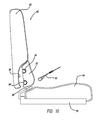
FIG. 1 is a perspective view of a portion of a vehicle seat having CRS anchors;
FIG. 2 is a perspective view of a portion of a vehicle seat in which the approximate locations of needed accessibility are required in the seat back;
FIG. 3 is a perspective view of a portion of a vehicle seat in which an approximate location of needed accessibility is required in the seat back;
FIG. 4 is a perspective view of a portion of a vehicle seat in which the approximate locations of needed accessibility are required in the seat base;
FIG. 5 is a perspective view of a portion of a vehicle seat in which an approximate location of needed accessibility is required in the seat base;
FIG. 6 is a front view of a vehicle seat shown without the seat back pad and the seat base pad to illustrate the wireframe rod available for attachment of the anchor concealing trim piece according to the disclosed inventive concept;
FIG. 7 is a perspective view of the underside of a vehicle bench seat pad illustrating the wireframe rod available for attachment of the anchor concealing trim piece according to the disclosed inventive concept;
FIG. 8 is a sectional view of a vehicle seat viewed from the side illustrating a removable anchor concealing trim piece according to a first embodiment of the disclosed inventive concept held in by hook-and-loop fasteners;
FIG. 9 is a sectional view of a vehicle seat similar to that of FIG. 8 but illustrating the removable anchor concealing trim piece having been removed and shown spaced apart from the seat;
FIG. 10 is a sectional view of a vehicle seat viewed from the side illustrating a removable anchor concealing trim piece according to a second embodiment of the disclosed inventive concept held in by a mechanical interlock feature;
FIG. 11 is a sectional view of a vehicle seat similar to that of FIG. 10 but illustrating the removable anchor concealing trim piece having been removed and shown spaced apart from the seat;
FIG. 12 is a sectional view of a vehicle seat viewed from the side illustrating a removable anchor concealing trim piece according to a variation of the second embodiment of the disclosed inventive concept that includes a release tab attached to the anchor concealing trim piece;
FIG. 13 is a perspective view of the anchor concealing trim piece of the vehicle seat embodiment illustrated in FIG. 12;
FIG. 14 is a sectional view of a vehicle seat viewed from the side illustrating a rotatable anchor concealing trim piece according to a third embodiment of the disclosed inventive concept in which the rotatable anchor concealing trim piece is rotatable between an anchor concealing position (as shown) and an anchor exposing position (not shown);
FIG. 15 is a perspective view of the rotatable anchor concealing trim piece of the vehicle seat embodiment illustrated in FIG. 14;
FIG. 16 is a view similar to that of FIG. 14 except the rotatable anchor concealing trim piece is shown rotated to its anchor exposing position;
FIG. 17 is a sectional view of a vehicle seat viewed from the side illustrating a rotatable anchor concealing trim piece according to a fourth embodiment of the disclosed inventive concept in which a rotatable anchor concealing trim piece is provided that may be locked in position against unintended rotation;
FIG. 18 is a sectional view of a vehicle seat viewed from the side illustrating a rotatable anchor concealing trim piece according to a fifth embodiment of the disclosed inventive concept in which a slidable anchor concealing trim piece is movable between an anchor concealing position (as shown) and an anchor exposing position (not shown); and
FIG. 19 is a view similar to that of FIG. 18 except the slidable anchor concealing trim piece is shown moved to its anchor exposing position.
DETAILED DESCRIPTION OF THE PREFERRED EMBODIMENT
In the following figures, the same reference numerals will be used to refer to the same components. In the following description, various operating parameters and components are described for different constructed embodiments. These specific parameters and components are included as examples and are not meant to be limiting.
Referring to FIG. 1, a perspective view of a portion of a vehicle seat is shown and is generally illustrated as 10. The vehicle seat 10 includes a seat back 12 and a seat base 14. CRS anchors 16 and 16′ are shown generally positioned at the area where the seat back 12 and the seat base 14 meet, as illustrated. A greater or lesser number of CRS anchors may be provided as is known in the art.
While FIG. 1 illustrates known locations of CRS anchors, attachment areas vary from vehicle seat to vehicle seat. Non-limiting examples of anchor accessibility locations are illustrated in FIGS. 2 through 5. Referring to these figures, a perspective view of a portion of a vehicle seat is shown and is generally illustrated as 20. The vehicle seat 20 includes a seat back 22 and a seat base 24.
In FIG. 2, access locations 26 and 26′ are illustrated in the lower portion of the seat back 22. In this configuration, it is desired to position a anchor concealing trim piece over each of the access locations 26 and 26′.
In FIG. 3, an elongated access location 28 is illustrated, also in the lower portion of the seat back 22. In this configuration, it is desired to position a single, elongated anchor concealing trim piece over the entire access location 28.
In FIG. 4, access locations 30 and 30′ are illustrated in the rearward portion of the seat base 24. In this configuration, it is desired to position an anchor concealing trim piece over each of the access locations 30 and 30′.
In FIG. 5, an elongated access location 32 is illustrated, also in the rearward portion of the seat base 24. In this configuration, it is desired to position a single, elongated anchor concealing trim piece over the entire access location 32.
The access locations shown in FIGS. 2 through 5 are suggestive only and are not intended as being limiting. It is to be understood that other locations may exist in either or both of the vehicle seat back 22 or the vehicle seat base 24.
The disclosed inventive concept includes removable, slidable or rotatable anchor concealing trim pieces as will be described below. An advantage of the disclosed inventive concept is that it may be incorporated into existing vehicle seats with the least amount of modification, and thus the least amount of expense. For example, attachment of the anchor concealing trim piece to the vehicle seat may be made by using existing seat structures, as illustrated in FIGS. 6 and 7.
Referring to FIG. 6, a vehicle seat 40 is generally illustrated having a seat back 42 and a seat base 44. A wireframe rod, such as wireframe rod 46, is conventionally provided in the seat back 42. The wireframe rod 46 is separate from the cushion foam and is usable as an attachment point for the concealing trim piece. A pair of CRS anchors 48 and 48′ is provided.
As the wireframe rod 46 (or some variation thereof) is conventionally provided as part of the vehicle seat 40, the disclosed inventive concept avoids the need to add new content to achieve attachment. The wireframe rod 46 is conveniently and favorably located directly above the CRS anchors 48 and 48′.
The provision of wireframe rods in the existing vehicle seat is not limited to the seat back of the vehicle seat. As illustrated in FIG. 7, the wireframe rod may also be provided in the seat base of the vehicle seat. Particularly, the underside of a seat base 50. The seat base 50 typically includes a skeletal wireframe 52 that may be used for convenient attachment of the concealing trim piece.
The concealing trim pieces of the disclosed inventive concept that may be used in conjunction with the seats are shown in various configurations and arrangements in FIGS. 8 through 19. The concealing trim pieces may be composed of a variety of materials, though conventional polyurethane foam is the material of choice. The heights, lengths, widths, depths and locations of the concealing trim piece can be varied to achieve the desired balance of anchor accessibility or visibility as well as styling and comfort. Thus the illustrated concealing trim pieces shown in FIGS. 8 through 19 are intended as being suggestive only and are not intended as being limiting.
FIGS. 8 and 9 disclose a first embodiment of the disclosed inventive concept. Referring to FIG. 8, a sectional view of a vehicle seat, generally illustrated as 60, is shown. The vehicle seat 60 includes a seat back 62 and a seat base 64 attached to a seat frame 66. CRS anchors, of which one, a CRS anchor 68, is shown, are conventionally provided and are anchored to a portion of the vehicle such as, for example, the seat frame 66. A CRS attachment element such as a web strap and clip 70 is provided for releasable attachment of the CRS (not shown) to the CRS anchor 68.
A concealing trim piece 72 is removably fitted into a trim piece pocket 74. The trim piece pocket 74 may extend below the concealing trim piece 72 and above the CRS anchor 68. The concealing trim piece 72 is releasably held in place by any of several releasable attachment structures, including, without limitation, first portions 76 and 76′ and second portions 78 and 78′ of a hook-and-loop fastening system. Other releasably attachable arrangements are possible. As a further variation of this and all embodiments of the disclosed inventive concept, the lower portion of the seat back 62 may have one or more openings that allow the consumer to have access to push out the concealing trim piece 72 if desired.
In FIG. 8, the concealing trim piece 72 is shown in its concealing position fitted into the trim piece pocket 74 and held in place by the first portions 76 and 76′ and second portions 78 and 78′ of the hook-and-loop fastening system. The area where the upper area of the outer surface of the concealing trim piece 72 meets the outer surface of the seat back 62 may be “shingled” for styling reasons, although this arrangement is not illustrated in FIG. 8 or 9.
To reveal the CRS anchor 68, the consumer removes the concealing trim piece 72 as illustrated in FIG. 9 and attachment of the CRS web strap and clip 70 to the CRS anchor 68 is made. Concealment of the CRS anchor 68 may be achieved once the CRS web strap and clip 70 is released by the consumer from the CRS anchor 68 and the concealing trim piece 72 is returned to its concealing position as shown in FIG. 8.
FIGS. 10 and 11 disclose a second embodiment of the disclosed inventive concept. This embodiment provides an alternative to the hook-and-loop fastening system of the first embodiment of the disclosed inventive concept shown in FIGS. 8 and 9 and discussed in relation thereto.
Referring to FIG. 10, a sectional view of a vehicle seat, generally illustrated as 80, is shown. The vehicle seat 80 includes a seat back 82 and a seat base 84 attached to a seat frame 86. CRS anchors, of which one, a CRS anchor 88, is shown, are conventionally provided and are anchored to a portion of the vehicle such as, for example, the seat frame 86. A CRS attachment element such as a CRS web strap and clip 90 is provided for releasable attachment of the CRS (not shown) to the CRS anchor 88.
The concealing trim piece 92 is releasably held in place by the releasable interconnection of the concealing trim piece 92 to a pair of transverse rods 94 and 94′ that are either locally embedded in the seat foam of the seat back 82 or are part of the skeleton of the vehicle seat. It is to be understood that while two transverse rods 94 and 94′ are shown, a greater or lesser number of transverse rods may be used. A trim piece pocket 96 is formed in the lower portion of the seat back 82.
As illustrated in FIG. 11, a pair of spaced apart channels 98 and 98′ is formed in the back side of the concealing trim piece 92. Accordingly, the transverse rods 94 and 94′ are releasably locked into the pair of spaced apart channels 98 and 98′ to thereby hold the concealing trim piece 92 in the trim piece pocket 96. It is to be understood that while the rods 94 and 94′ are illustrated as being transverse, it is possible that the rods could also be oriented vertically.
While in FIG. 10 the concealing trim piece 92 is shown in its concealing position fitted into the trim piece pocket 96 and held in place by the locking interrelationship of the transverse rods 94 and 94′ with the channels 98 and 98′ having embedded clips (such as C-clips made from a plastic or a metal), to reveal the CRS anchor 88, the consumer removes the concealing trim piece 92 as illustrated in FIG. 11. With the concealing trim piece 92 thus removed, attachment of the CRS web strap and clip 90 to the CRS anchor 88 may be made. Concealment of the CRS anchor 88 may once again be achieved after the CRS web strap and clip 90 is released by the consumer from the CRS anchor 88 and the concealing trim piece 92 is returned to its concealing position as shown in FIG. 10.
A variation of the second embodiment of the disclosed inventive concept is illustrated in FIG. 12 in which the concealing trim piece 92 has a release tab 100. The release tab 100 may include the requisite ISO and may be a cloth tag sewn into concealing trim piece 92 of the type that may be found on various vehicle seats. The release tab 100 may be attached to the concealing trim piece 92 to both identify anchor location and to provide a surface to grab onto to remove the concealing trim piece 92.
The disclosed inventive concept may have further variations related to removability of the concealing trim piece versus rotatability or movability of the concealing trim piece. Particularly, the embodiments shown in FIGS. 14 through 19 provide alternatives to the need for the consumer to remove and store the concealing trim piece as is the case in the embodiments shown in FIGS. 8 through 13.
Referring to FIGS. 14 through 16, a third embodiment of the disclosed inventive concept is illustrated. Referring to FIG. 14, a sectional view of a vehicle seat, generally illustrated as 110, is shown. The vehicle seat 110 includes a seat back 112 and a seat base 114 attached to a seat frame 116. CRS anchors, of which one, a CRS anchor 118, is shown, are conventionally provided and are anchored to a portion of the vehicle such as, for example, the seat frame 116. A CRS attachment element such as a web strap and clip 120 is provided for releasable attachment of the CRS (not shown) to the CRS anchor 118.
A rotatable concealing trim piece 122 is rotatably fitted in a trim piece pocket 124. The trim piece pocket 124 may extend below the rotatable concealing trim piece 122 and above the CRS anchor 118. The rotatable concealing trim piece 122 is rotatably mounted on a transverse rod 128 that is fitted into a channel 128 formed in the rotatable concealing trim piece 122. The channel 128 may be defined by a C-clip or other retention element. The C-clip-lined channel 128 is shown in close-up in FIG. 15. A release tab 130 is preferably attached to the rotatable concealing trim piece 122.
In FIG. 14, the rotatable concealing trim piece 122 is shown in its concealing position rotated to its concealing position in the trim piece pocket 124 such that the CRS anchor 118 is concealed. To reveal the CRS anchor 118, the consumer rotates the rotatable concealing trim piece 122 as illustrated in FIG. 16 and attachment of the CRS web strap and clip 120 to the CRS anchor 118 is made. Concealment of the CRS anchor 118 may be achieved once the CRS web strap and clip 120 is released by the consumer from the CRS anchor 118 and the rotatable concealing trim piece 122 is rotated back to its concealing position as shown in FIG. 14.
A variation of the third embodiment of the disclosed inventive concept illustrated in FIGS. 14 through 16 and discussed in relation thereto is a fourth embodiment of the disclosed inventive concept illustrated in FIG. 17. Referring thereto, a sectional view of a vehicle seat, generally illustrated as 140, is shown. The vehicle seat 140 includes a seat back 142 and a seat base 144 attached to a seat frame 146. CRS anchors, of which one, a CRS anchor 148, is shown, are conventionally provided and are anchored to a portion of the vehicle such as, for example, the seat frame 146. A CRS attachment element such as a web strap and clip 150 is provided for releasable attachment of the CRS (not shown) to the CRS anchor 148.
A rotatable concealing trim piece 152 is rotatably fitted in a trim piece pocket 154. The rotatable concealing trim piece 152 is rotatably mounted on a transverse rod 156 that is fitted into a channel 158 formed in the rotatable concealing trim piece 152. The channel 158 may be defined by a C-clip or other retention element.
The fourth embodiment of the disclosed inventive concept differs from the third embodiment in that a positive stop is provided to prevent unintended rotation of the rotatable concealing trim piece 152 about the transverse rod 156. The positive stop is provided in the form of a second transverse rode 160 against which the rotatable concealing trim piece 152 rests when in its concealing position as illustrated in FIG. 17.
A fifth embodiment of the disclosed inventive concept is illustrated in FIGS. 18 and 19. Like the third and fourth embodiments discussed above in relation to FIGS. 14 through 17, the fifth embodiment requires only movement and not removal of the concealing trim piece to reveal the CRS anchor.
Referring to FIG. 18, a sectional view of a vehicle seat, generally illustrated as 170, is shown. The vehicle seat 170 includes a seat back 172 and a seat base 174 attached to a seat frame 176. CRS anchors, of which one, a CRS anchor 178, is shown, are conventionally provided and are anchored to a portion of the vehicle such as, for example, the seat frame 176. A CRS attachment element such as a web strap and clip 180 is provided for releasable attachment of the CRS (not shown) to the CRS anchor 178.
A slidable concealing trim piece 182 is slidably positioned in a slidable trim piece pocket 184. The slidable trim piece pocket 184 may be of any shape including the shape illustrated. The slidable trim piece pocket 184, which may be a friction contact path, allows the slidable concealing trim piece 182 to be moved upwards into the seat back 172.
In addition, a rearward-positioned portion of the seat base 174 may be movable to allow greater access to the CRS anchor 178. This portion, a rotating concealing trim piece 186, rotates on an optional pivot rod 188. An attachment rod 190 is provided. A C-clip 192 is preferably fitted to the rotating concealing trim piece 186. In their concealing positions as illustrated in FIG. 18, the slidable concealing trim piece 182 is moved downward and the rotating concealing trim piece 186 remains in its raised position.
If the consumer desires to have access to the CRS anchor 178, the slidable concealing trim piece 182 is moved upward into the seat back 172 and the rotating concealing trim piece 186 is rotated downward until the attachment rod 190 locks into the C-clip 192 as illustrated in FIG. 19.
The system for concealing a CRS anchor according to the disclosed inventive concept may be employed in any vehicle seat conventionally fitted with a CRS anchor. While specific locations of the CRS anchor have been illustrated in the figures and described in relation thereto, it is to be understood that the CRS anchors may be provided in locations other than those shown and described. However, the concealing trim piece of the disclosed inventive concept would find application regardless of the location of the CRS anchors.
One skilled in the art will readily recognize from such discussion, and from the accompanying drawings and claims that various changes, modifications and variations can be made therein without departing from the true spirit and fair scope of the invention as defined by the following claims.

Claims (20)

What is claimed is:
1. A system for selectively concealing a child safety seat anchor in a vehicle, the system comprising:
a seat;
a seat anchor;
a concealing trim piece pocket having a back wall formed in said seat; and
a concealing trim piece having a front wall, said piece being rotatable attached to said seat, said piece being movable between an anchor concealing position in which said front wall faces away from said back wall and an anchor revealing position in which said front wall faces said back wall.
2. The system for selectively concealing a child safety seat anchor in a vehicle of claim 1 wherein said concealing trim piece is a removable piece, the system further including hook-and-loop fasteners for attaching said removable piece to said seat.
3. The system for selectively concealing a child safety seat anchor in a vehicle of claim 1 further including a rod fixed to said seat and wherein said trim piece includes a channel for releasable attachment to said rod.
4. The system for selectively concealing a child safety seat anchor in a vehicle of claim 3 wherein said channel includes a C-clip.
5. The system for selectively concealing a child safety seat anchor in a vehicle of claim 1 further including a consumer-manipulated tab attached to said concealing trim piece.
6. The system for selectively concealing a child safety seat anchor in a vehicle of claim 1 further including a rod fixed to said seat and wherein said concealing trim piece is rotatably attached to said rod, said concealing trim piece being rotatable between an anchor concealing position and an anchor revealing position.
7. The system for selectively concealing a child safety seat anchor in a vehicle of claim 6 wherein said seat further includes a positive stop structure that limits rotation of said concealing trim piece.
8. The system for selectively concealing a child safety seat anchor in a vehicle of claim 1 wherein said concealing trim piece comprises a slidably movable concealing trim piece and said rotatably movable concealing trim piece.
9. The system for selectively concealing a child safety seat anchor in a vehicle of claim 8 wherein said seat includes a seat back and a seat base and wherein concealing trim piece pocket is formed in said seat back, said slidably movable concealing trim piece being slidably positioned in said concealing trim piece pocket.
10. A system for selectively concealing a child safety seat anchor in a vehicle, the system comprising:
a seat;
a seat anchor;
a concealing trim piece pocket having a back wall formed in said seat; and
a concealing trim piece having a front wall, said piece being rotatably movable between a position in which said front wall faces away from said back wall and a position in which said front wall faces said back wall.
11. The system for selectively concealing a child safety seat anchor in a vehicle of claim 10 wherein said concealing trim piece is removably attached to said seat.
12. The system for selectively concealing a child safety seat anchor in a vehicle of claim 11 further including hook-and-loop fasteners for attaching said concealing trim piece to said seat.
13. The system for selectively concealing a child safety seat anchor in a vehicle of claim 10 further including a rod fixed to said seat and wherein said concealing trim piece includes a channel for releasable attachment to said rod.
14. The system for selectively concealing a child safety seat anchor in a vehicle of claim 13 wherein said channel includes a C-clip.
15. The system for selectively concealing a child safety seat anchor in a vehicle of claim 13 further including a consumer-manipulated tab attached to said concealing trim piece.
16. The system for selectively concealing a child safety seat anchor in a vehicle of claim 10 further including a rod fixed to said seat and wherein said concealing trim piece is rotatably attached to said rod, said concealing trim piece being rotatable between an anchor concealing position and an anchor revealing position.
17. The system for selectively concealing a child safety seat anchor in a vehicle of claim 16 wherein said seat further includes a positive stop structure that limits rotation of said concealing trim piece.
18. The system for selectively concealing a child safety seat anchor in a vehicle of claim 10 wherein said concealing trim piece comprises a slidably movable concealing trim piece and said rotatably movable concealing trim piece.
19. The system for selectively concealing a child safety seat anchor in a vehicle of claim 18 wherein said seat includes a seat back and a seat base and wherein concealing trim piece pocket is formed in said seat back, said slidably movable concealing trim piece being slidably positioned in said concealing trim piece pocket.
20. A seat for a vehicle comprising:
a seat back
a seat base;
a safety seat attachment anchor;
a concealing trim piece pocket having a back wall formed in said seat; and
a concealing trim piece having a front wall, said piece being rotatably movable between an anchor concealing position in which said front wall faces away from said back wall and an anchor revealing position in which said front wall faces said back wall.
US14/640,306 2015-03-06 2015-03-06 Movable inserts for concealing child safety seat anchors in a vehicle Active US9493099B2 (en)

Priority Applications (5)

Application Number Priority Date Filing Date Title
US14/640,306 US9493099B2 (en) 2015-03-06 2015-03-06 Movable inserts for concealing child safety seat anchors in a vehicle
RU2016105444A RU2016105444A (en) 2015-03-06 2016-02-18 SYSTEM FOR SELECTIVE HIDDENING OF FASTENING OF THE CHILD'S SAFETY SEAT (OPTIONS) AND SEAT FOR THE VEHICLE
CN201610097538.8A CN105936225B (en) 2015-03-06 2016-02-23 Movable insert for hiding a child safety seat anchor in a vehicle
DE102016103886.5A DE102016103886A1 (en) 2015-03-06 2016-03-03 Movable inserts for concealing child safety seat anchorages in a vehicle
MX2016002884A MX2016002884A (en) 2015-03-06 2016-03-04 Movable inserts for concealing child safety seat anchors in a vehicle.

Applications Claiming Priority (1)

Application Number Priority Date Filing Date Title
US14/640,306 US9493099B2 (en) 2015-03-06 2015-03-06 Movable inserts for concealing child safety seat anchors in a vehicle

Publications (2)

Publication Number Publication Date
US20160257229A1 US20160257229A1 (en) 2016-09-08
US9493099B2 true US9493099B2 (en) 2016-11-15

Family

ID=56739084

Family Applications (1)

Application Number Title Priority Date Filing Date
US14/640,306 Active US9493099B2 (en) 2015-03-06 2015-03-06 Movable inserts for concealing child safety seat anchors in a vehicle

Country Status (5)

Country Link
US (1) US9493099B2 (en)
CN (1) CN105936225B (en)
DE (1) DE102016103886A1 (en)
MX (1) MX2016002884A (en)
RU (1) RU2016105444A (en)

Cited By (7)

* Cited by examiner, † Cited by third party
Publication number Priority date Publication date Assignee Title
US9981581B2 (en) * 2016-10-31 2018-05-29 Toyota Boshoku Kabushiki Kaisha Vehicle seat
US10052980B2 (en) * 2016-08-24 2018-08-21 Nissan North America, Inc. Vehicle seat assembly
US10220739B2 (en) * 2016-10-26 2019-03-05 Toyota Boshoku Kabushiki Kaisha Vehicle seat
US10384570B2 (en) 2017-04-18 2019-08-20 Ford Global Technologies, Llc Child-seat restraint system
US10414298B2 (en) * 2016-03-08 2019-09-17 Ts Tech Co., Ltd. Vehicle seat
US11007909B2 (en) 2018-08-14 2021-05-18 Honda Motor Co., Ltd. Seat and seat trim structure for a vehicle and vehicle having same
US20230095604A1 (en) * 2021-09-28 2023-03-30 Lear Corporation Seat assembly and method of assembly

Families Citing this family (7)

* Cited by examiner, † Cited by third party
Publication number Priority date Publication date Assignee Title
JP6276042B2 (en) * 2014-01-22 2018-02-07 テイ・エス テック株式会社 Vehicle seat
US9821686B2 (en) * 2015-03-06 2017-11-21 Ford Global Technologies, Llc Enhanced fixed anchor accessibility for child safety seat anchors in a vehicle
US9688166B2 (en) * 2015-09-17 2017-06-27 Ford Global Technologies, Llc Rotatable anchors providing enhanced child restraint system interface accessibility
DE102018203311A1 (en) 2018-03-06 2019-09-12 Bayerische Motoren Werke Aktiengesellschaft vehicle seat
DE102018213506A1 (en) * 2018-08-10 2020-02-13 Bayerische Motoren Werke Aktiengesellschaft Device for fastening child seats for a vehicle
CN109774552A (en) * 2019-03-13 2019-05-21 上海沃雨电子科技有限公司 ISOFIX mechanism and its fixed steel wire and ISOFIX connector
DE102019208486B4 (en) * 2019-06-12 2023-12-14 Lear Corporation FAIRING COVER FOR ANCHORING TO A VEHICLE SEAT ASSEMBLY

Citations (26)

* Cited by examiner, † Cited by third party
Publication number Priority date Publication date Assignee Title
US4662676A (en) * 1985-09-11 1987-05-05 Ken Havelock Arm tray for chair
US4674795A (en) * 1986-07-10 1987-06-23 Nelson Jonathan M Chair frame
US5249839A (en) * 1991-11-12 1993-10-05 Steelcase Inc. Split back chair
US5829828A (en) * 1997-05-19 1998-11-03 Asfaw; Aklog Self securing concealable seat cover
US6394552B1 (en) * 2001-01-04 2002-05-28 Tung-Hua Su Chair backrest with an adjustable headrest
US6416128B1 (en) * 2000-05-31 2002-07-09 Ts Tech Co., Ltd. Vehicle seat
US20020104190A1 (en) 2001-01-23 2002-08-08 Donal Moore Child tether cover
US6582016B1 (en) * 2001-07-31 2003-06-24 Johnson Controls Technology Company Seat trim closeout for isofix systems
US6601523B2 (en) * 2001-12-12 2003-08-05 The Boeing Company Easy cleanable food tray
US6601917B1 (en) 1999-03-03 2003-08-05 Intier Automotive Inc. Cover for child seat anchor
US20040066074A1 (en) * 2002-10-04 2004-04-08 Rod Ovitt Pivoting seat apparatus
US7093896B2 (en) * 2002-11-01 2006-08-22 Fuji Jukogyo Kabushiki Kaisha Vehicle seat
US20060261651A1 (en) * 2005-05-02 2006-11-23 Graco Children's Products Inc. Child vehicle safety seat
US20060261650A1 (en) * 2005-05-02 2006-11-23 Graco Children's Products Inc. Child vehicle safety seat
US7281763B1 (en) 2006-06-29 2007-10-16 Honda Motor Co., Ltd. Automotive seat for mounting child seat thereon
US7427103B2 (en) * 2004-03-17 2008-09-23 Intier Automotive Inc. Removable bolster for ISOFIX
US7699396B2 (en) 2007-01-23 2010-04-20 Lear Corporation Seat assembly having an internal mounting bracket and a seat cover including a closure structure
US7722105B2 (en) 2006-12-29 2010-05-25 Honda Motor Co., Ltd. Anchor cap for child safety seat
US7758096B2 (en) 2006-11-15 2010-07-20 Suzuki Motor Corporation Child seat anchor apparatus and partition trim
US20120032490A1 (en) * 2010-08-09 2012-02-09 Teutonia Kinderwagenfabrik Gmbh Stroller Seat Assembly with Calf Support
US8328280B2 (en) * 2010-09-01 2012-12-11 Honda Motor Co., Ltd. Hinged center bolster for center ISO FIX attachment in a high bolster rear seat
US20140028067A1 (en) * 2012-07-30 2014-01-30 Veycle Design Co., Ltd. Seat pad adjustable chair
US8678497B2 (en) 2010-08-30 2014-03-25 Honda Motor Co., Ltd. Seating arrangement for a vehicle
US8740309B2 (en) * 2011-10-18 2014-06-03 Toyota Boshoku Kabushiki Kaisha Seat gap hiding structure
US8789868B1 (en) * 2013-03-06 2014-07-29 Ford Global Technologies, Llc Luggage retention system
US8801073B1 (en) * 2013-03-06 2014-08-12 Ford Global Technologies, Llc Luggage retention system

Family Cites Families (3)

* Cited by examiner, † Cited by third party
Publication number Priority date Publication date Assignee Title
ATE156432T1 (en) * 1991-05-14 1997-08-15 Atoma Int Inc VEHICLE SEAT
CN1923566A (en) * 2005-08-31 2007-03-07 高田株式会社 Child car seat
JP6029552B2 (en) * 2013-08-13 2016-11-24 株式会社タチエス Vehicle seat

Patent Citations (26)

* Cited by examiner, † Cited by third party
Publication number Priority date Publication date Assignee Title
US4662676A (en) * 1985-09-11 1987-05-05 Ken Havelock Arm tray for chair
US4674795A (en) * 1986-07-10 1987-06-23 Nelson Jonathan M Chair frame
US5249839A (en) * 1991-11-12 1993-10-05 Steelcase Inc. Split back chair
US5829828A (en) * 1997-05-19 1998-11-03 Asfaw; Aklog Self securing concealable seat cover
US6601917B1 (en) 1999-03-03 2003-08-05 Intier Automotive Inc. Cover for child seat anchor
US6416128B1 (en) * 2000-05-31 2002-07-09 Ts Tech Co., Ltd. Vehicle seat
US6394552B1 (en) * 2001-01-04 2002-05-28 Tung-Hua Su Chair backrest with an adjustable headrest
US20020104190A1 (en) 2001-01-23 2002-08-08 Donal Moore Child tether cover
US6582016B1 (en) * 2001-07-31 2003-06-24 Johnson Controls Technology Company Seat trim closeout for isofix systems
US6601523B2 (en) * 2001-12-12 2003-08-05 The Boeing Company Easy cleanable food tray
US20040066074A1 (en) * 2002-10-04 2004-04-08 Rod Ovitt Pivoting seat apparatus
US7093896B2 (en) * 2002-11-01 2006-08-22 Fuji Jukogyo Kabushiki Kaisha Vehicle seat
US7427103B2 (en) * 2004-03-17 2008-09-23 Intier Automotive Inc. Removable bolster for ISOFIX
US20060261651A1 (en) * 2005-05-02 2006-11-23 Graco Children's Products Inc. Child vehicle safety seat
US20060261650A1 (en) * 2005-05-02 2006-11-23 Graco Children's Products Inc. Child vehicle safety seat
US7281763B1 (en) 2006-06-29 2007-10-16 Honda Motor Co., Ltd. Automotive seat for mounting child seat thereon
US7758096B2 (en) 2006-11-15 2010-07-20 Suzuki Motor Corporation Child seat anchor apparatus and partition trim
US7722105B2 (en) 2006-12-29 2010-05-25 Honda Motor Co., Ltd. Anchor cap for child safety seat
US7699396B2 (en) 2007-01-23 2010-04-20 Lear Corporation Seat assembly having an internal mounting bracket and a seat cover including a closure structure
US20120032490A1 (en) * 2010-08-09 2012-02-09 Teutonia Kinderwagenfabrik Gmbh Stroller Seat Assembly with Calf Support
US8678497B2 (en) 2010-08-30 2014-03-25 Honda Motor Co., Ltd. Seating arrangement for a vehicle
US8328280B2 (en) * 2010-09-01 2012-12-11 Honda Motor Co., Ltd. Hinged center bolster for center ISO FIX attachment in a high bolster rear seat
US8740309B2 (en) * 2011-10-18 2014-06-03 Toyota Boshoku Kabushiki Kaisha Seat gap hiding structure
US20140028067A1 (en) * 2012-07-30 2014-01-30 Veycle Design Co., Ltd. Seat pad adjustable chair
US8789868B1 (en) * 2013-03-06 2014-07-29 Ford Global Technologies, Llc Luggage retention system
US8801073B1 (en) * 2013-03-06 2014-08-12 Ford Global Technologies, Llc Luggage retention system

Cited By (8)

* Cited by examiner, † Cited by third party
Publication number Priority date Publication date Assignee Title
US10414298B2 (en) * 2016-03-08 2019-09-17 Ts Tech Co., Ltd. Vehicle seat
US10052980B2 (en) * 2016-08-24 2018-08-21 Nissan North America, Inc. Vehicle seat assembly
US10220739B2 (en) * 2016-10-26 2019-03-05 Toyota Boshoku Kabushiki Kaisha Vehicle seat
US9981581B2 (en) * 2016-10-31 2018-05-29 Toyota Boshoku Kabushiki Kaisha Vehicle seat
US10384570B2 (en) 2017-04-18 2019-08-20 Ford Global Technologies, Llc Child-seat restraint system
US11007909B2 (en) 2018-08-14 2021-05-18 Honda Motor Co., Ltd. Seat and seat trim structure for a vehicle and vehicle having same
US20230095604A1 (en) * 2021-09-28 2023-03-30 Lear Corporation Seat assembly and method of assembly
US11731538B2 (en) * 2021-09-28 2023-08-22 Lear Corporation Seat assembly and method of assembly

Also Published As

Publication number Publication date
CN105936225A (en) 2016-09-14
MX2016002884A (en) 2016-10-18
DE102016103886A1 (en) 2016-09-08
CN105936225B (en) 2020-04-10
RU2016105444A (en) 2017-08-23
US20160257229A1 (en) 2016-09-08

Similar Documents

Publication Publication Date Title
US9493099B2 (en) Movable inserts for concealing child safety seat anchors in a vehicle
US7390059B2 (en) Vehicle seat
EP2233350B1 (en) Soft cover for covering a seat
CN107685665B (en) Modular back panel subassembly
JP6180268B2 (en) Vehicle seat
US8328280B2 (en) Hinged center bolster for center ISO FIX attachment in a high bolster rear seat
US8905478B2 (en) Child safety seat with structural support
CN107685664B (en) Inner bracket base plate trim cover attachment
JP2000272597A (en) Seat for aircraft
US20180056820A1 (en) Vehicle seat assembly
CN107685666B (en) Inner bracket base plate mechanically locked with head protection headrest guide shaft sleeve
CA2929341A1 (en) Isofix trim retainer
US9457765B2 (en) Vehicle seat with a belt buckle
US9855874B2 (en) Passive head support device for a vehicle passenger
WO2015058072A1 (en) Vehicle seat with structural cover for seat back frame
JP4058688B2 (en) Seat belt device
CN103129434A (en) Two-way zipper closeout for folding head restraint slots
CN109969053A (en) Vehicles shoulder belt exports decorative components
US20170349067A1 (en) Seat System
US20090045660A1 (en) Fastening bracket for a chair
JP6163645B2 (en) Vehicle entry / exit structure
JP5991185B2 (en) Vehicle seat
RU2448849C9 (en) Automotive seat
CN218141160U (en) Vehicle seat
JP5632601B2 (en) Vehicle seat structure

Legal Events

Date Code Title Description
AS Assignment

Owner name: FORD GLOBAL TECHNOLOGIES, LLC, MICHIGAN

Free format text: ASSIGNMENT OF ASSIGNORS INTEREST;ASSIGNOR:RUTHINOWSKI, RICHARD EDWARD;REEL/FRAME:037693/0975

Effective date: 20160209

AS Assignment

Owner name: FORD GLOBAL TECHNOLOGIES, LLC, MICHIGAN

Free format text: CORRECTIVE ASSIGNMENT TO CORRECT THE APPLICATION NUMBER 14/460,306 TO 14640306 PREVIOUSLY RECORDED AT REEL: 037693 FRAME: 0975. ASSIGNOR(S) HEREBY CONFIRMS THE ASSIGNMENT;ASSIGNOR:RUTHINOWSKI, RICHARD EDWARD;REEL/FRAME:038065/0121

Effective date: 20160215

STCF Information on status: patent grant

Free format text: PATENTED CASE

MAFP Maintenance fee payment

Free format text: PAYMENT OF MAINTENANCE FEE, 4TH YEAR, LARGE ENTITY (ORIGINAL EVENT CODE: M1551); ENTITY STATUS OF PATENT OWNER: LARGE ENTITY

Year of fee payment: 4

MAFP Maintenance fee payment

Free format text: PAYMENT OF MAINTENANCE FEE, 8TH YEAR, LARGE ENTITY (ORIGINAL EVENT CODE: M1552); ENTITY STATUS OF PATENT OWNER: LARGE ENTITY

Year of fee payment: 8