US9485380B2 - Image reading apparatus, image forming apparatus and computer readable medium storing program - Google Patents
Image reading apparatus, image forming apparatus and computer readable medium storing program Download PDFInfo
- Publication number
- US9485380B2 US9485380B2 US14/620,839 US201514620839A US9485380B2 US 9485380 B2 US9485380 B2 US 9485380B2 US 201514620839 A US201514620839 A US 201514620839A US 9485380 B2 US9485380 B2 US 9485380B2
- Authority
- US
- United States
- Prior art keywords
- illumination
- front surface
- back surface
- unit
- image reading
- Prior art date
- Legal status (The legal status is an assumption and is not a legal conclusion. Google has not performed a legal analysis and makes no representation as to the accuracy of the status listed.)
- Active
Links
Images


Classifications
-
- H—ELECTRICITY
- H04—ELECTRIC COMMUNICATION TECHNIQUE
- H04N—PICTORIAL COMMUNICATION, e.g. TELEVISION
- H04N1/00—Scanning, transmission or reproduction of documents or the like, e.g. facsimile transmission; Details thereof
- H04N1/024—Details of scanning heads ; Means for illuminating the original
- H04N1/028—Details of scanning heads ; Means for illuminating the original for picture information pick-up
- H04N1/02815—Means for illuminating the original, not specific to a particular type of pick-up head
Definitions
- the present invention relates to an image reading apparatus, an image forming apparatus, and a computer readable medium storing a program.
- an image reading apparatus comprising an illumination unit that is disposed so as to be moved relative to a recording medium and illuminates the recording medium with light beams of plural colors that are circulated in predetermined order; a reading unit that reads an image recorded on the recording medium by receiving reflection light that is produced as a result of the illumination unit's illuminating the recording medium during the moving relative to the recording medium; and a control unit that controls the illumination unit so that a difference between a first illumination interval between adjoining colors within each illumination cycle of light beams of the plural colors circulated in the predetermined order and a second illumination interval from illumination with light of the last color of the cycle to illumination with light of the first color of the next cycle is determined based on a reading resolution of the reading unit.
- FIG. 1 is a general perspective view showing an example appearance of an image forming apparatus according to a first exemplary embodiment.
- FIG. 2 shows a general perspective view showing an example appearance of part of an image reading unit of the image forming apparatus according to the first exemplary embodiment.
- FIG. 3 is a schematic side view showing an example configuration of the image reading unit of the image forming apparatus according to the first exemplary embodiment.
- FIG. 4 is a block diagram showing an example hardware configuration of an electrical system of the image forming apparatus according to the first exemplary embodiment.
- FIG. 5 is a block diagram showing an example hardware configuration of an electrical system of an image reading unit body of the image reading unit of the image forming apparatus according to the first exemplary embodiment.
- FIG. 6 is a flowchart of a main part of an example lighting control process according to the first exemplary embodiment.
- FIG. 7 is the other part of the example lighting control process according to the first exemplary embodiment.
- FIG. 8 is a flowchart of an example reading control process according to the first exemplary embodiment.
- FIG. 9 is a time chart showing an example conventional timing relationship between trigger output intervals and on-periods of LEDs which are turned on in response to respective triggers in a case that the image reading resolution of a CIS is 400 dpi.
- FIG. 10 is a time chart showing an example timing relationship between trigger output intervals and on-periods of the LEDs which are turned on in response to respective triggers in the lighting control process according to the first exemplary embodiment in a case that the image reading resolution of the CIS is 400 dpi.
- FIG. 11 is a conceptual diagram showing example reading intervals employed in the case of a speed for high resolution, example reading intervals employed conventionally in the case of a speed for low resolution, and example reading intervals employed in the first exemplary embodiment (the CIS is used) in the case of a speed for low resolution.
- FIG. 12 is a conceptual diagram showing a secondary storage unit that is stored with a lighting control program and a reading control program in the first exemplary embodiment.
- FIG. 13 is a schematic side view showing an example configuration of a structural aspect of image reading apparatus according to second and third exemplary embodiments.
- FIG. 14 is a block diagram showing an example configuration of an electric system of the image reading apparatus according to the second exemplary embodiment.
- FIG. 15 is a flowchart of an example cycle signal transmission process according to the second exemplary embodiment and a fourth exemplary embodiment.
- FIG. 16 is a flowchart of an example first lighting control process according to the second exemplary embodiment.
- FIG. 17 is a flowchart of an example second lighting control process according to the second exemplary embodiment.
- FIG. 18 is a time chart showing example state changes of cycle signals, light emission periods of a front surface lamp, light emission periods of a back surface lamp, and a current consumption in the second exemplary embodiment.
- FIG. 19 is a block diagram showing an example configuration of an electric system of the image reading apparatus according to the third exemplary embodiment.
- FIG. 20 is a flowchart of an example cycle signal transmission process according to the third exemplary embodiment.
- FIG. 21 is a flowchart of an example first lighting control process according to the third exemplary embodiment.
- FIG. 22 is a flowchart of an example second lighting control process according to the third exemplary embodiment.
- FIG. 23 is a time chart showing example state changes of first cycle signals, light emission periods of a front surface lamp, second cycle signals, light emission periods of a back surface lamp, and a current consumption in the third exemplary embodiment.
- FIG. 24 is a schematic side view showing an example configuration of a structural aspect of an image reading apparatus according to a fourth exemplary embodiment.
- FIG. 25 is a block diagram showing an example configuration of an electric system of the image reading apparatus according to the fourth exemplary embodiment.
- FIG. 26 is a flowchart of an example LED identification information transmission process according to the fourth exemplary embodiment.
- FIG. 27 is a flowchart of an example front surface LED setting process according to the fourth exemplary embodiment.
- FIG. 28 is a flowchart of a main part of an example a first lighting control process according to the fourth exemplary embodiment.
- FIG. 29 is a flowchart of the other part of the example a first lighting control process according to the fourth exemplary embodiment.
- FIG. 30 is a flowchart of an example back surface LED setting process according to the fourth exemplary embodiment.
- FIG. 31 is a flowchart of a main part of an example second lighting control process according to the fourth exemplary embodiment.
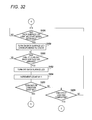
- FIG. 32 is a flowchart of the other part of the example second lighting control process according to the fourth exemplary embodiment.
- FIG. 33 is a time chart showing a first example set of state changes of cycle signals, on-periods of front surface LEDs, on-periods of back surface LEDs, and a current consumption in the fourth exemplary embodiment.
- FIG. 34 is a time chart showing a second example set of state changes of cycle signals, on-periods of front surface LEDs, on-periods of back surface LEDs, and a current consumption in the fourth exemplary embodiment.
- FIG. 35 is a block diagram showing an example configuration for realizing the individual steps of the first lighting control processes and the front surface LED setting process by a software configuration.
- FIG. 36 is a block diagram showing an example configuration for realizing the individual steps of the second lighting control processes and the front surface LED setting process by a software configuration.
- an example image forming apparatus 10 is equipped with an image reading unit 12 which is an example image reading apparatus according to the invention, an image forming unit 14 , sheets housing units 16 , and a user interface (UI) 18 C.
- image reading unit 12 which is an example image reading apparatus according to the invention
- image forming unit 14 sheets housing units 16
- UI user interface
- the image reading unit 12 is equipped with a document stage 20 and an ejection stage 22 .
- the top surface of the document stage 20 is provided with a pair of guide members 24 A and 24 B. Capable of being moved manually in the width of document pages placed on the document stage 20 , the pair of guide members 24 A and 24 B guide document pages placed on the document stage 20 so that each document page is conveyed in the conveying direction.
- the image reading unit 12 takes in document pages one by one, reads an image on each document page by a line-sequential method, and acquires image information representing the read-out image.
- the image reading unit 12 outputs the acquired image information to a CPU 72 (described later) and then ejects the document page to the ejection stage 22 .
- the line-sequential method is a method of reading one line of a document page by each reading operation by turning on one of red (R), green (G), and blue (B) light sources while switching between them as the light sources and a line sensor are moved relative to the document page.
- the light sources are a first LED 60 A, a second LED 60 B, and a third LED 60 C (described later).
- the line sensor is what is called a monochrome image sensor which is composed of photoelectric conversion elements 66 .
- the above-mentioned relative movement has the following three modes: a document page is moved whereas the positions of the light sources and the line sensor are fixed; the light sources and the line sensor are moved whereas the position of a document page is fixed; and the light sources and the line sensor are moved in a direction opposite to a direction in which a document page is moved.
- the plural sheets housing units 16 house respective sets of sheets of different sizes (a sheet is an example recording medium).
- the image forming unit 14 picks up a sheet from one sheets housing unit 16 and forms an image on the sheet.
- Example images to be formed on a sheet are an image represented by image information that is acquired from the image reading unit 12 by the CPU 72 (described later), an image represented by image information that is acquired from an external apparatus 86 A (described later) by the CPU 72 , and a reference image for image quality adjustment (what is called a patch).
- the image forming unit 14 ejects, to an ejection stage 26 A, a sheet on which an image has been formed.
- the image forming method may be either an electrophotographic method or an inkjet method.
- the UI unit 18 C is equipped with a touch screen display 18 A for displaying an image and switches 18 B.
- the touch screen display 18 A and the switches 18 B serve to receive, from a user of the image forming apparatus 10 , various instructions, examples of which are a scan start instruction which is an instruction for causing the image reading unit 12 to start image reading and an instruction for causing the image forming unit 14 to start image formation.
- the touch screen display 18 A displays various kinds of information such as a result of processing that has been performed in response to a received instruction and an alarm.
- the image reading unit 12 includes a body 30 A and a document feeder 32 A which is an example relative speed changing unit of the invention.
- the document feeder 32 A is equipped with the document stage 20 and the ejection stage 22 .
- the body 30 A houses an image reading unit body 50 A and the top surface of the body 30 A is formed with a rectangular opening 34 A.
- the opening 34 A is larger than an A3-size document and is closed by a platen glass 38 C on which a document page 36 (see FIG. 3 ) is to be placed.
- the document page 36 is a sheet on which an image is recorded in an image recording area.
- the image reading unit 12 employs a colorless, transparent glass plate as the platen glass 38 C, the invention is not limited to such a case; the platen glass 38 C may be any transparent document stage.
- the top surface of the body 30 A is provided with fixing portions 38 A and 38 B to which hinge members (not shown) are fixed that are provided on the bottom surface of the document feeder 32 A (see FIG. 3 ).
- the hinge members allow document feeder 32 A to be rotated between a position where to expose the platen glass 38 C and a position where to cover the platen glass 38 C.
- a rectangular-frame-shaped document setting guide 40 A is formed around the platen glass 38 C.
- the top surface of the document setting guide 40 A is slightly higher than the top surface of the platen glass 38 C, as a result of which a document page 36 is positioned by bringing its corner portion into contact with side surfaces of a corner portion of the document setting guide 40 A.
- the top surface of the document setting guide 40 A is provided with a positioning mark (not shown) and document size labels (not shown).
- the positioning mark is a mark to be used in registering the corner portion of a document page 36 with that of the document setting guide 40 A.
- the document size labels are marks where ends of a document page 26 having a regular size (B5, A4, B4, or A3) should be located when it is placed on the platen glass 38 C with its corner portion registered with that of the document setting guide 40 A.
- a document page 36 is fed to a document flipping unit (not shown) from the document stage 20 .
- the topmost document page 36 is fed to the document flipping unit.
- the document page 36 is flipped by the document flipping unit and then passes a reading region on the platen glass 38 C. Image reading is performed while the document page 36 is passing the reading region.
- the document page 36 is then ejected to the ejection stage 22 .
- the image reading unit body 50 A includes a contact image sensor (CIS) 52 A, an image processing circuit 54 A, and a motor 56 A.
- the CIS 52 A and the image processing circuit 54 A are mounted on a carriage 58 , which receives drive power of the motor 56 A and is thereby moved in the X direction (auxiliary scanning direction; see FIG. 3 ) which corresponds to the longitudinal direction of the opening 34 A.
- the CIS 52 A has a first LED (light-emitting diode) 60 A having a red (R) emission wavelength range, a second LED 60 B having a green (G) emission wavelength range, and a third LED 60 C having a blue (B) emission wavelength range.
- the first LED 60 A, the second LED 60 B, and the third LED 60 C are an example illumination unit of the invention.
- the first LED 60 A, the second LED 60 B, and the third LED 60 C are driven sequentially so as to emit R light, G light, and B light in predetermined circulation color order, that is, R ⁇ G ⁇ B ⁇ R ⁇ G ⁇ B . . . (one cycle: R ⁇ G ⁇ B).
- R ⁇ G ⁇ B the first color and the last color of each cycle
- the first color and the last color may be G and R or B and G, respectively.
- the first LED 60 A, the second LED 60 B, and the third LED 60 C will be referred to as an “LED(s) 60 ” when it is not necessary to discriminate between them.
- the CIS 52 A has a lightguide 62 A and a focusing unit 64 A.
- the CIS 52 A also has photoelectric conversion elements 66 which are part of an example reading unit of the invention and an analog front end (AFE) 68 E which is part of the example reading unit and a control unit of the invention.
- AFE 68 E is a circuit commonly called an analog preprocessor.
- the lightguide 62 A extends long in the Y direction (main scanning direction; see FIG. 3 ) which corresponds to the shorter-axis direction of the opening 34 A.
- the LEDs 60 are attached to one end of the lightguide 62 A, which guides light that is emitted from a turned-on one of the LEDs 60 to a document page 36 in line form.
- the focusing unit 64 A is a lens unit in which plural erecting, equal-magnification, imaging forming lens elements are arranged in the main scanning direction.
- the focusing unit 64 A focuses reflection light that is reflected from the document page 36 when the document page 36 is illuminated with light that is emitted from a turned-on LED 60 and guided by the lightguide 62 A.
- the plural photoelectric conversion elements 66 which are arranged in the Y direction, receive and perform photoelectric conversion on (an image of) the reflection light focused by the focusing unit 64 A and thereby generate and output pieces of analog image information which are electrical signals representing reception light quantities.
- the pieces of mage information generated by and output from the photoelectric conversion elements 66 are image information representing an R image (R image information), image information representing a G image (G image information), and image information representing a B image (B image information).
- R image information an R image
- G image information image information representing a G image
- B image information image information representing a B image
- the AFE 68 E adjusts the image information received from the photoelectric conversion elements 66 using an amplifier, an A/D converter, a filter, etc. (none of which are shown) and outputs resulting digital image information, an example of which is 16-bit image information.
- the image processing circuit 54 A has, as functions of processing, in circulation color order starting from a particular color, the image information received from the AFE 68 E, functions of performing various kinds of image processing such as shading correction, gamma conversion correction, pixel arrangement conversion.
- the particular color is R, the invention is not limited to such a case; it may be G or B.
- the image forming apparatus 10 is equipped with a controller 70 A, which is equipped with a CPU (central processing unit) 72 , a primary storage unit 74 A, and a secondary storage unit 76 A.
- the primary storage unit 74 A is a volatile memory (e.g., RAM (random access memory)) that is used as a working area etc. when various programs are run.
- the secondary storage unit 76 A is a nonvolatile memory that is stored in advance with control programs for controlling operations of the image forming apparatus 10 , various parameters, etc. Examples of the secondary storage unit 76 A are a flash memory and a hard disk drive.
- the CPU 72 , the primary storage unit 74 A, and the secondary storage unit 76 A are connected to each other by a bus 8 .
- the image forming apparatus 10 is equipped with an input/output interface (hereinafter referred to as “I/O”) 80 which is electrically connected to various input/output devices and serves for exchange of various kinds of information between the CPU 72 and the various input/output devices.
- I/O input/output interface
- the image forming apparatus 10 is equipped with the image reading unit 12 , the image forming unit 14 , and the UI unit 18 C as input/output devices that are connected to the I/O 80 and thereby electrically connected to the CPU 72 by a bus 78 .
- the image forming apparatus 10 is also equipped with other input/output devices, that is, an external interface (I/F) 82 A and a communication I/F 84 A.
- I/F external interface
- the external I/F serves for exchange of various kinds of information between the external device and the CPU 72 .
- the communication I/F 84 A serves for exchange of various kinds of information with an external apparatus 86 A connected to the communication medium.
- An example of the external apparatus 86 A is a personal computer.
- the CPU 72 recognizes operation statuses of the input/output devices, controls the input/output devices, and performs other kinds of processing on them by exchanging various kinds of information with them via the BUS 78 and the I/O 80 .
- the image reading unit body 50 A is equipped with a motor drive circuit 90 A which is an example relative speed changing unit of the invention.
- the motor drive circuit 90 A is connected to the motor 56 A and is also connected to the I/O 80 by a signal line 93 A.
- a motor control signal is input to the motor drive circuit 90 A from the CPU 72 via the I/O 80 and the signal line 93 A in response to a scan start instruction that is received by the UI unit 18 C.
- the motor control signal is a signal including information that indicates a rotation speed of the motor 56 A.
- the motor drive circuit 90 A controls the motor 56 A according to the received motor control signal.
- the carriage 58 receives drive power of the motor 56 A and the CIS 52 A is thereby moved in the X direction.
- the CIS 52 A is moved in a state that a document page 36 is place on the platen glass 38 C.
- the movement speed of the CIS 52 A is generally classified into a movement speed for high resolution and a movement speed for low resolution.
- the movement speed for high resolution is a movement speed that is employed when the image reading resolution of the CIS 52 A is higher than or equal to 600 dpi.
- the movement speed for low resolution is a movement speed that is employed when the image reading resolution of the CIS 52 A is lower than 600 dpi.
- the CIS 52 A is equipped with an LED drive circuit 92 A, which is connected to the first LED 60 A, the second LED 60 B, and the third LED 60 C.
- the AFE 68 E is connected to the LED drive circuit 92 A and is also connected to the I/O 80 by signal lines 94 A, 196 , 198 , 100 A, and 102 A.
- an LED control start signal is generated by the CPU 72 and output to the AFE 68 E from the CPU 72 via the I/O 80 and the signal line 196 .
- the AFE 68 E starts controlling the LEDs 60 via the LED drive circuit 92 A.
- An LED control end signal is input to the AFE 68 E from the CPU 72 via the I/O 80 and the signal line 196 .
- the LED control end signal is generated by the CPU 72 when an image reading end condition is satisfied.
- the AFE 68 E finishes controlling the LEDs 60 via the LED drive circuit 92 A.
- An example image reading end condition is that an image reading operation on one document page 36 , that is, a movement of the CIS 52 A relative to the one document page 36 , has been completed.
- a resolution signal is input to the AFE 68 E from the CPU 72 the I/O 80 and the signal line 198 .
- a conveying speed signal is input to the AFE 68 E from the CPU 72 the I/O 80 and the signal line 100 A.
- a motor control signal is further input to the AFE 68 E from the CPU 72 the I/O 80 and the signal line 93 A.
- the resolution signal is a signal indicating an image reading resolution of the CIS 52 A, which is determined by, for example, an instruction that is received by the UI unit 18 C.
- the conveying speed signal is a signal indicating a document conveying speed of the document feeder 32 A.
- the document feeder 32 A conveys a document page 36 in a state that the carriage 58 is stopped.
- the document conveying speed of the document feeder 32 A is generally classified into a conveying speed for high resolution and a conveying speed for low resolution.
- the conveying speed for high resolution is a conveying speed that is employed when the image reading resolution of the CIS 52 A is higher than or equal to 600 dpi.
- the conveying speed for low resolution is a conveying speed that is employed when the image reading resolution of the CIS 52 A is lower than 600 dpi.
- the above-mentioned movement speed for high resolution and conveying speed for high resolution will be referred to as a speed for high resolution and above-mentioned movement speed for low resolution and conveying speed for low resolution will be referred to as a speed for low resolution.
- the LED drive circuit 92 A turns on the first LED 60 A, the second LED 60 B, and the third LED 60 C in the circulation color order under the control of the AFE 68 E.
- the AFE 68 E is connected to the photoelectric conversion elements 66 .
- the AFE 68 E is equipped with a signal generation circuit 102 A and an internal register 104 A.
- the signal generation circuit 102 A generates (and outputs) a trigger and a sync signal on the basis of a basic clock signal (basic CLK signal) that is received from the CPU 72 via the I/O 80 and the signal line 94 A.
- the trigger is a signal indicating turn-on timing for each LED 60 and is input to the LED drive circuit 92 A.
- the LED drive circuit 92 A turns on each LED 60 in response to a trigger that is received from the AFE 68 E.
- the sync signal is a sync signal indicating image information output timing.
- the exemplary embodiment employs, as an example relationship between turning-on of each LED 60 and the image information output timing, a relationship that after turning-on of an LED 60 , image information is output before output of the next trigger.
- the next trigger may be same as the sync signal. Since turning-on of an LED and output of a sync signal are repeated in the circulation color order, the trigger and the sync signal may be same signal.
- a high resolution range may be defined as a resolution range in which color deviations (described later) due to the relationship between the speed of the CIS 52 A relative to a document page 36 and the line density of an image on the document page 36 do not occur, with a low resolution range defined as the other resolution range.
- the high resolution range and the low resolution range may be determined in advance by a simulation, a test using an actual machine, or the like.
- the speed for low resolution is higher than that for high resolution. Therefore, if, for example, the speed for low resolution is employed and an image on a document page 36 is read at a resolution that is lower than 600 dpi by turning on the LEDs 60 in the circulation color order at fixed (monotonic) cycles, color deviations may occur depending on the relationship between the speed for low resolution and the line density of the image on the document page 36 .
- color deviations as used herein means color deviations that cannot be disregarded, for example, color deviations that are difficult to correct by image processing of the image forming circuit 54 A.
- Color deviations also occur also at the speed for high resolution as long as a line-sequential method is employed as a reading method because of differences between R, G, and B reading positions.
- color deviations being addressed in the exemplary embodiment are ones that are larger than color deviations that occur at the speed for high resolution, that is, color deviations that occur at the speed for low resolution which is higher than that for high resolution.
- a trigger output interval is derived according to a relationship between an image reading resolution of the CIS 52 A and a movement speed of the CIS 52 A relative to a document page 36 .
- the AFE 68 E is equipped with the internal register 104 A which is stored with first output interval information and pieces of second output interval information. Selection from the first output interval information and pieces of second output interval information is made by the AFE 68 E according to the movement speed of the CIS 52 A relative to a document page 36 , that is, whether it is a speed for high resolution or a speed for low resolution.
- the first output interval information and the second output interval information will be referred to as “output interval information” when it is not necessary to discriminate between them.
- the output interval information is information indicating a trigger output interval.
- An example of the output interval information is the number of clock pulses that determines a trigger output interval.
- the difference between the trigger output interval indicated by the first output interval information and that indicated by each piece of second output interval information is determined according to an image reading resolution of the CIS 52 A.
- the trigger output interval indicated by the first output interval information is fixed irrespective of the image reading resolution of the CIS 52 A.
- the trigger output interval indicated by each piece of second output interval information is longer than that indicated by the first output interval information.
- the pieces of second output interval information are determined for respective image reading resolutions of the CIS 52 A; the trigger output interval indicated by the second output interval information becomes longer as the image reading resolution becomes lower.
- the trigger output interval indicated by the first output interval information corresponds to the term “first illumination interval” as used in the invention, and the trigger output interval indicated by the second output interval information corresponds to the term “second illumination interval” as used in the invention.
- the AFE 68 E judges whether the movement speed of the CIS 52 A relative to a document page 36 is a speed for high resolution or a speed for low resolution on the basis of a resolution signal and a conveying speed signal or a resolution signal and a motor control signal.
- the AFE 68 E selectively acquires the first output interval information or a piece of second output interval information from the internal register 104 A according to a result of the judgment as to whether the movement speed of the CIS 52 A relative to the document page 36 is a speed for high resolution or a speed for low resolution.
- the AFE 68 E outputs triggers at an output interval that is indicated by the first output interval information or the second output interval information acquired from the internal register 104 A.
- the AFE 68 E performs processing corresponding to processing performed by a general AFE on each of pieces of image information that are received from the photoelectric conversion elements 66 in the circulation color order starting from R. Connected to the image processing circuit 54 A, the AFE 68 E outputs pieces of image information to the image processing circuit 54 A in the circulation color order in synchronism with output of sync signals.
- the image reading unit body 50 A is equipped with the image processing circuit 54 A, which has an FPGA (field programmable fate array) and a CPU (not shown) incorporating an ASIC (application-specific integrated circuit). Connected to the I/O 80 , the image processing circuit 54 A performs predetermined plural kinds of processing such as shading correction on the image information received from the AFE 68 E and outputs resulting image information to a predetermined output destination such as the CPU 72 via the I/O 80 .
- predetermined plural kinds of processing such as shading correction on the image information received from the AFE 68 E and outputs resulting image information to a predetermined output destination such as the CPU 72 via the I/O 80 .
- FIGS. 6 and 7 a description will be made of a lighting control process that is executed by the AFE 68 E when a scan start instruction is received by the UI unit 18 C.
- a description will be made of a case that the CIS 52 A performs image reading by moving the CIS 52 A in the X direction relative to a document page 36 placed on the platen glass 38 C and an instruction indicating a resolution of image reading by the CIS 52 A has already been received by the UI unit 18 C.
- the AFE 68 E judges whether an LED control start condition which is a condition for a start of a control for turning on the LEDs 60 is satisfied or not.
- the LED control start condition is that an LED control start signal, a resolution signal, and a conveying speed signal or an LED control start signal, a resolution signal, and a motor control signal should have been received.
- this condition is just an example and another condition may be added.
- step S 200 If it is judged at step S 200 that the LED control start condition is not satisfied (S 200 : no), step S 200 is executed again. If it is judged at step S 200 that the LED control start condition is satisfied (S 200 : yes), the process moves to step S 202 .
- step S 202 it is judged whether the resolution indicated by the resolution signal is lower than 600 dpi which is an example threshold value used in the invention. If it is judged at step S 202 that the resolution indicated by the resolution signal is higher than or equal to 600 dpi (S 202 : no), the process moves to step S 204 .
- 600 dpi is an example threshold value used in the invention.
- the AFE 68 E outputs a trigger to the LED drive circuit 92 A.
- the LED drive circuit 92 A turns on an LED 60 according to the circulation color order. Reflection light that is produced by illuminating the image recording area of the document page 36 with light emitted from the turned-on LED 60 is received by the photoelectric conversion elements 66 and image information is thereby generated.
- the AFE 68 E judges whether or not a first turn-on interval has elapsed from the end of execution of step S 204 .
- the first turn-on interval is a time that is equal to the trigger output interval indicated by the first output interval information stored in the internal register 104 A.
- step S 206 If it is judged at step S 206 that the first turn-on interval has not elapsed yet from the end of execution of step S 204 (S 206 : no), the process moves to step S 208 . If it is judged at step S 206 that the first turn-on interval has elapsed from the end of execution of step S 204 (S 206 : yes), the process returns to step S 204 .
- the AFE 68 E judges whether an LED control end condition which is a condition for finishing a control for turning on the LEDs 60 is satisfied or not.
- the LED control end condition is that an LED control end signal should have been received.
- this condition is just an example and it may be added with another condition or replaced by another condition.
- step S 208 If it is judged at step S 208 that the LED control end condition is not satisfied (S 208 : no), the process returns to step S 206 . If it is judged at step S 208 that the LED control end condition is satisfied (S 208 : yes), the lighting control process is finished.
- step S 210 the AFE 68 E judges whether or not the relative movement speed of the CIS 52 A relative to the document page 36 is a speed for low resolution on the basis of the motor control signal, for example. If it is judged at step S 210 that the relative movement speed of the CIS 52 A relative to the document page 36 is not a speed for low resolution, that is, it is a speed for high resolution (S 210 : no), the process moves to step S 204 . If it is judged at step S 210 that the relative movement speed of the CIS 52 A relative to the document page 36 is a speed for low resolution (S 210 : yes), the process moves to step S 212 .
- the AFE 68 E outputs a trigger to the LED drive circuit 92 A.
- the LED drive circuit 92 A turns on an LED 60 according to the circulation color order. Reflection light that is produced by illuminating the image recording area of the document page 36 with light emitted from the turned-on LED 60 is received by the photoelectric conversion elements 66 and image information is thereby generated.
- the AFE 68 E judges whether or not turning-on of one cycle of the circulation color order has been completed.
- the term “turning-on of one cycle” means turning-on of the first LED 60 A, turning-on of the second LED 60 B, and turning-on of the third LED 60 C combined. In each cycle, turning-on of the first LED 60 A, turning-on of the second LED 60 B, and turning-on of the third LED 60 C are first turning-on, second turning-on, and third turning-on, respectively.
- step S 216 the AFE 68 E judges whether or not the first turn-on interval has elapsed from the end of execution of step S 212 . If it is judged at step S 216 that the first turn-on interval has not elapsed yet from the end of execution of step S 212 (S 216 : no), the process moves to step S 218 . If it is judged at step S 216 that the first turn-on interval has elapsed from the end of execution of step S 212 (S 216 : yes), the process returns to step S 212 .
- step S 218 the AFE 68 E judges whether the LED control end condition is satisfied or not. If it is judged at step S 218 that the LED control end condition is not satisfied (S 218 : no), the process returns to step S 216 . If it is judged at step S 218 that the LED control end condition is satisfied (S 218 : yes), the lighting control process is finished.
- step S 214 judges whether or not a second turn-on interval has elapsed from the end of execution of step S 212 .
- the second turn-on interval is a time that is equal to the trigger output interval indicated by a piece of second output interval information stored in the internal register 104 A.
- the trigger output interval indicated by the second output interval information varies depending on the resolution indicated by the resolution signal that is received by the AFE 68 E. Therefore, second turn-on interval also varies depending on the resolution indicated by the resolution signal.
- step S 220 If it is judged at step S 220 that the second turn-on interval has not elapsed yet from the end of execution of step S 212 (S 220 : no), the process moves to step S 222 . If it is judged at step S 220 that the second turn-on interval has elapsed from the end of execution of step S 212 (S 220 : yes), the process returns to step S 212 .
- step S 222 the AFE 68 E judges whether the LED control end condition is satisfied or not. If it is judged at step S 222 that the LED control end condition is not satisfied (S 222 : no), the process returns to step S 220 . If it is judged at step S 222 that the LED control end condition is satisfied (S 222 : yes), the lighting control process is finished.
- triggers are output at fixed (monotonic) intervals irrespective of where each cycle stands in the circulation color order and the LEDs 60 are turned on in the circulation color order in response to the respective triggers.
- the output interval of triggers belonging to adjoining cycles is different from the output interval of triggers within a cycle (exemplified in FIG. 10 ). That is, because of steps S 212 -S 222 , in each cycle, triggers are output at the first turn-on intervals. The first trigger of the next cycle is output when the second turn-on interval has elapsed from the output of the last trigger of the current cycle.
- the LEDs 60 are turned on in the circulation color order in response to respective triggers.
- the AFE 68 E judges whether or not image information has been generated by the photoelectric conversion elements 66 . For example, this is done by judging whether a time has elapsed or not that is predetermined as a time to be taken from output of one trigger to generation of image information by the photoelectric conversion elements 66 .
- step S 250 If it is judged at step S 250 that image information has been generated by the photoelectric conversion elements 66 (S 250 : yes), the process moves to step S 252 . If it is judged at step S 250 that image information has not been generated yet by the photoelectric conversion elements 66 (S 250 : no), the process moves to step S 254 .
- step S 252 the AFE 68 E reads part of an image by acquiring the image information from the photoelectric conversion elements 66 . Then the process moves to step S 254 .
- step S 254 the AFE 68 E judges whether an LED control end condition is satisfied or not. If it is judged at step S 254 that the LED control end condition is not satisfied (S 254 : no), the process returns to step S 250 . If it is judged at step S 254 that the LED control end condition is satisfied (S 254 : yes), the reading control process is finished.
- image portions are read in the circulation color order at fixed (monotonic) reading intervals irrespective of where each cycle stands in the circulation color order. That is, for example, in the case where the movement speed of the CIS 52 A relative to a document page 36 is 600 dpi which is a speed for high resolution, the reading intervals between image portions of the respective colors that are circulated in the prescribed order are fixed (monotonic) as shown in FIG. 11 . This reading interval is equal to the trigger output interval indicated by the first output interval information.
- the reading intervals in each cycle are the same as in the case where the movement speed of the CIS 52 A relative to a document page 36 is a speed for high resolution. But the reading interval from reading of the last color of each cycle to reading of the first color of the next cycle is longer than the reading interval of the case that the movement speed of the CIS 52 A relative to a document page 36 is a speed for high resolution. That is, the reading interval from reading of the last color of each cycle to reading of the first color of the next cycle is equal to the trigger output interval indicated by the second output interval information.
- the illumination intervals between R, G, and B light beams in each cycle are set identical (as exemplified in FIG. 11 ), the invention is not limited to such a case.
- the illumination intervals between adjoining ones (R and G or G and B) of R, G, and B light beams in each cycle (RGB) may be different from each other.
- the invention is not limited to such a case.
- the invention holds even in the case that the resolution is changed with the relative speed kept constant as long as the relationship between the conventional illumination intervals shown in FIG. 11 and the illumination intervals according to the exemplary embodiment shown in FIG. 11 is maintained.
- image reading by the CIS 52 A is performed by moving the CIS 52 A relative to a document page 36 placed on the platen glass 38 C
- the invention is not limited to such a case.
- the lighting control process may be executed in a case that image reading by the CIS 52 A is performed by conveying a document page 36 with the document feeder 32 A. That is, the lighting control process may be executed in a case that image reading by the CIS 52 A is performed in a state that the CIS 52 A is being moved relative to a document page 36 .
- the first turn-ob interval is fixed irrespective of the movement speed of the CIS 52 A relative to a document page 36
- the invention is not limited to such a case.
- the first turn-ob interval may be varied according to the movement speed of the CIS 52 A relative to a document page 36 .
- the lighting control process and the reading control process described in the above exemplary embodiment are just examples. It goes without saying that such modifications as deletion of unnecessary steps, addition of new steps, and change of execution order of steps are possible without departing from the spirit and scope of the invention.
- the individual steps of each of the lighting control process and the reading control process described in the above exemplary embodiment are executed by the AFE 68 E, they may be implemented by a software configuration using a computer by running a program.
- the individual steps of each of various kinds of processes may be implemented by a combination of a hardware configuration and a software configuration.
- an example method for implementing the individual steps of each of the lighting control process and the reading control process described in the above exemplary embodiment by a software configuration is to store a lighting control program 150 and a reading control program 152 in the secondary storage unit 76 A in advance.
- the CPU 72 causes the AFE 68 E to execute the individual steps of each of the lighting control process and the reading control process by running the lighting control program 150 and the reading control program 152 stored in the secondary storage unit 76 A.
- the lighting control program 150 and the reading control program 152 stored in the secondary storage unit 76 A need not always be stored in the secondary storage unit 76 A from the beginning.
- the lighting control program 150 and the reading control program 152 may be stored in a portable storage medium to be used being connected to the image forming apparatus 10 such as an SSD (solid-state drive), an IC card, a magneto-optical disc, or a CD-ROM.
- the CPU 72 acquires the lighting control program 150 and the reading control program 152 from the portable storage medium and runs them.
- the lighting control program 150 and the reading control program 152 may be stored in a storage unit of an external computer such as a server to be connected to the image forming apparatus 10 via a communication medium. In this case, the CPU 72 acquires the lighting control program 150 and the reading control program 152 from the external computer and runs them.
- pieces of image information of the three colors R, G, and B are generated by illuminating the image recording area of a document page 36 with light beams of R, G, and B emitted from the respective LEDs 60
- the invention is not limited to such a case.
- pieces of image information of yellow (Y), magenta (M), and cyan (C) may be generated by illuminating the image recording area of a document page 36 with light beams of Y, M, and C emitted from respective light sources such as LEDs.
- pieces of image information of predetermined plural colors may be generated by illuminating the image recording area of a document page 36 with light beams of the predetermined plural colors emitted from respective LEDs.
- an example image reading apparatus 10 A includes a document feeder 12 A (dual auto document feeder (DADF)) and a front surface image reading unit 14 A.
- DADF dual auto document feeder
- the document feeder 12 A includes a document stage 20 , plural conveying roll pairs 26 , a back surface image reading unit 28 , a document ejection stage 30 , and a reference plate 46 .
- Document pages 18 on which images are recorded are stacked on the document stage 20 .
- a pickup roll 22 A and the plural conveying roll pairs 26 are disposed along a conveyance path 24 .
- a document page 18 is picked up from the document stage 20 by the pickup roll 22 A and then conveyed by the plural conveying roll pairs 26 .
- a document page 18 that has been subjected to reading processing by at least one of the front surface image reading unit 14 A and the back surface image reading unit 28 is ejected to the document ejection stage 30 .
- the document page 18 is an example of the recording medium of the invention.
- the back surface image reading unit 28 includes a back surface line sensor 28 A and a back surface lamp 28 B which is an example back surface illumination unit of the invention.
- the back surface lamp 28 B which is long in the main scanning direction, illuminates the top surface of the reference plate 46 or the back surface of a document page 18 that is passing over the reference plate 46 .
- the back surface line sensor 28 A reads an image on the back surface of a document page 18 or the top surface of the reference plate 46 through photoelectric conversion by receiving, pixel by pixel, reflection light produced by illuminating the back surface of the document page 18 or the top surface of the reference plate 46 with the back surface lamp 28 B that is turned on, and outputs resulting reading data.
- the reference plate 46 is a white plate that is long in the main scanning direction, and is disposed so as to be opposed to the back surface image reading unit 28 .
- An example of the reference plate 46 is a white resin plate or a metal plate that is painted in white.
- the front surface image reading unit 14 A is equipped with a platen glass 32 to which a reference plate 35 is attached.
- the reference plate 35 is a white plate that is long in the main scanning direction.
- a front surface reading position which is a position where to read an image on the front surface of a document page 18 being conveyed by the document feeder 12 A exists adjacent to the reference plate 35 on the top surface of the platen glass 32 .
- a front surface lamp 34 which is an example front surface illumination unit of the invention, a first reflection mirror 36 A, a second reflection mirror 38 , and a third reflection mirror 40 are disposed under the platen glass 32 .
- the front surface lamp 34 which is long in the main scanning direction, illuminates the bottom surface of the reference plate 35 or the front surface of a document page 18 that is passing the front surface reading position.
- the first reflection mirror 36 A receives reflection light coming from the front surface of a document page 18 or the bottom surface of the reference plate 35 and reflects it toward the second reflection mirror 38 .
- the second reflection mirror 38 receives the reflection light coming from the first reflection mirror 36 A and reflects it toward the third reflection mirror 40 .
- the third reflection mirror 40 receives the reflection light coming from the second reflection mirror 38 and reflects it toward a lens 42 .
- the front surface image reading unit 14 A is equipped with a front surface line sensor 44 .
- Reflection light that is produced by illuminating the front surface of a document page 18 or the bottom surface of the reference plate 35 with the front surface lamp 34 that is turned on shines on the front surface line sensor 44 via the reflection mirrors 36 A, 38 , and 40 and the lens 42 .
- the front surface line sensor 44 reads an image on the front surface of the document page 18 or the bottom surface of the reference plate 35 through photoelectric conversion by receiving the incident reflection light pixel by pixel, and outputs resulting reading data.
- document pages 18 placed on the document stage 20 are picked up by the pickup roll 22 A one by one and fed to the conveyance path 24 .
- a document page 18 that has been fed to the conveyance path 24 is conveyed to the front surface reading position of the front surface image reading unit 14 A by the conveying roll pairs 26 , whereby an image on the front surface of the document page 18 is read by the front surface image reading unit 14 A.
- the document page 18 is conveyed to the back surface image reading unit 28 which is disposed downstream of the front surface reading position in the conveying direction.
- An image on the back surface of the document page 18 is read by the back surface image reading unit 28 , and the document page 18 is then ejected to the document ejection stage 30 .
- the front surface lamp 34 , the first reflection mirror 36 A, the second reflection mirror 38 , and the third reflection mirror 40 are movable in the auxiliary scanning direction (in the example shown in FIG. 13 , in the direction indicated by arrow A and the direction opposite to it). Therefore, an image recorded on a document page 18 that is placed on the top surface of the platen glass 32 can be read by moving the front surface lamp 34 that is turned on, the first reflection mirror 36 A, the second reflection mirror 38 , and the third reflection mirror 40 in the auxiliary scanning direction.
- the image reading apparatus 10 A employs a CCD line sensor that consists of plural CCDs (charge-coupled devices) as an example of each of the back surface line sensor 28 A and the front surface line sensor 44 .
- CCD line sensor that consists of plural CCDs (charge-coupled devices)
- the invention is not limited to such a case; for example, such a solid-state imaging device as a CMOS (complementary metal-oxide-semiconductor) image sensor may be employed.
- CMOS complementary metal-oxide-semiconductor
- a CIS like the back surface image reading unit 28 may be used, in which case the CIS is moved in the direction indicated by arrow A. In this case, the first reflection mirror 36 A, the second reflection mirror 38 , the third reflection mirror 40 , and the lens 42 are not necessary.
- the image reading apparatus 10 A employs an LED(s) (light-emitting diode(s)) as an example of each of the back surface lamp 28 B and the front surface lamp 34 .
- LED(s) light-emitting diode(s)
- the invention is not limited to such a case; for example, a fluorescent lamp may be used.
- the LED(s) may be of such a type that LEDs are arranged in the main scanning direction or an LED is disposed at an end in the main scanning direction.
- the image reading apparatus 10 A includes a controller 50 , an image reading control unit 52 which is an example output unit of the invention, a DADF control unit 54 , a back surface image reading control unit 56 , and a UI (user interface) 60 .
- the controller 50 controls the whole of the image reading apparatus 10 A.
- the controller 50 receives an image signal (reading data) from each of the image reading control unit 52 and the back surface image reading control unit 56 .
- the controller 50 also receives a signal indicating a user instruction or the like from the UI 60 .
- the image reading control unit 52 controls the whole of an image reading process that is executed by the image reading apparatus 10 A. More specifically, image reading control unit 52 controls the DADF control unit 54 , the back surface image reading control unit 56 , the front surface line sensor 44 , a scan control unit 72 A, and a front surface illumination control unit 76 which is an example control unit of the invention. In the second exemplary embodiment, the image reading control unit 52 is implemented as a CPU (central processing unit).
- the image reading control unit 52 is connected to a front surface ROM (read-only memory) 68 , a front surface RAM (random access memory) 70 , and a front surface NVM (nonvolatile memory) 71 .
- the front surface ROM 68 and the front surface NVM 71 are stored with various programs for reading of an image on the front surface of a document page 18 and various kinds of information etc. to be used for that purpose.
- the various programs include a cycle signal transmission program 68 A which is stored in the front surface ROM 68 in the example of FIG. 14 .
- the front surface RAM 70 is a memory that is used when the image reading control unit 52 operates.
- Various programs for reading of an image on the front surface of a document page 18 are developed temporarily in the front surface RAM 70 .
- various data that are necessary for reading of an image on the front surface of a document page 18 are stored temporarily in the front surface RAM 70 .
- the cycle signal transmission program 68 A is stored in the front surface ROM 68 , it need not always be stored in the front surface ROM 68 from the beginning.
- the cycle signal transmission program 68 A may be stored in a portable storage medium to be used being connected to the image reading apparatus 10 A such as an SSD (solid-state drive), an IC card, a magneto-optical disc, or a CD-ROM.
- the image reading control unit 52 acquires the cycle signal transmission program 68 A from the portable storage medium and runs it.
- the cycle signal transmission program 68 A may be stored in a storage unit of an external computer such as a server to be connected to the image reading apparatus 10 A via a communication medium. In this case, the image reading control unit 52 acquires the cycle signal transmission program 68 A from the external computer and runs it.
- the scan control unit 72 A performs a control relating to a scan for reading of a document page 18 and also controls a motor 74 , which serves to move the front surface lamp 34 and the mirrors 36 A, 38 , and 40 shown in FIG. 13 together.
- the front surface illumination control unit 76 controls the front surface lamp 34 .
- the image reading apparatus 10 A is equipped with a back surface illumination control unit 77 which is an example control means of the invention.
- the back surface illumination control unit 77 controls the back surface lamp 28 B under the control of the front surface illumination control unit 76 .
- the front surface illumination control unit 76 and the back surface illumination control unit 77 are implemented as an ASIC (application-specific integrated circuit), they may be implemented as a CPU.
- the DADF control unit 54 controls the document feeder 12 A.
- the DADF control unit 54 receives information from sensors 62 and roller control units 64 which control respective motors 66 A for controlling the above-described pickup roll 22 A and conveying roll pairs 26 .
- An example of the sensors 62 is a sensor for detecting, for example, whether or not the document feeder 12 A is opened over the front surface image reading unit 14 A.
- the back surface image reading control unit 56 controls the back surface image reading unit 28 .
- the back surface image reading control unit 56 is connected to a back surface ROM 82 , a back surface RAM 84 , and a back surface NVM 86 .
- the back surface ROM 82 and the back surface RAM 84 are stored with various programs for operation of the back surface image reading control unit 56 and various kinds of information etc. to be used for that purpose.
- the back surface RAM 84 is a memory that is used when the back surface image reading control unit 56 operates.
- the cycle signal transmission process is executed as the image reading control unit 52 runs the cycle signal transmission program 68 A.
- Cycle signals are signals that define illumination cycles of respective sets of a first illumination period and a second illumination period.
- first illumination period means an on-period of the front surface lamp 34 , that is, a period in which the front surface lamp 34 emits light.
- second illumination period means an on-period of the back surface lamp 28 B, that is, a period in which the back surface lamp 28 B emits light.
- the interval between cycle signals, that is, a cycle defined by the cycle signals is determined according to an image reading resolution. For example, the cycle becomes shorter as the image reading resolution becomes higher.
- step S 102 the image reading control unit 52 judges whether or not a one-cycle time has elapsed from the end of execution of step S 100 . If it is judged at step S 102 that the one-cycle time has elapsed from the end of execution of step S 100 (S 102 : yes), the process returns to step S 100 . If it is judged at step S 102 that the one-cycle time has not elapsed yet from the end of execution of step S 100 (S 102 : no), the process moves to step S 104 .
- the image reading control unit 52 judges whether a condition for termination of the cycle signal transmission process is satisfied or not.
- An example of the condition for termination of the cycle signal transmission process is that reading of images on the front surface and the back surface of every one of document pages 18 stacked on the document stage 20 should have been completed.
- Other examples are that an image reading termination instruction to terminate reading of images on the front surface and the back surface of every one of document pages 18 stacked on the document stage 20 should have been received by the UI 60 , and that a failure of the image reading apparatus 10 A should have been detected by the controller 50 , the image reading control unit 52 , the DADF control unit 54 , or the back surface image reading control unit 56 .
- step S 104 If it is judged at step S 104 that the condition for termination of the cycle signal transmission process is not satisfied (S 104 : no), the process returns to step S 102 . If it is judged at step S 104 that the condition for termination of the cycle signal transmission process is satisfied (S 104 : yes), the cycle signal transmission process is finished.
- the transmission of cycle signals that is, horizontal sync signals LSync, may be continued all the time.
- step S 110 the front surface illumination control unit 76 judges whether or not it has received a cycle signal transmitted as a result of execution of step S 100 of the cycle signal transmission process. If it is judged at step S 110 that a cycle signal has not been received yet (S 110 : no), the process moves to step S 120 . If it is judged at step S 110 that a cycle signal has been received (S 110 : yes), the process moves to step S 112 .
- step S 112 the front surface illumination control unit 76 turns on the front surface lamp 34 . Then the process moves to step S 114 .
- turning-on of the front surface lamp 34 as a result of execution of step S 112 means a start of a first illumination period.
- step S 114 the front surface illumination control unit 76 judges whether a time to turn off the front surface lamp 34 has arrived or not.
- time to turn off the front surface lamp 34 means a time when a half-cycle time has elapsed from a rise of the cycle signal. If it is judges at step S 114 that the time to turn off the front surface lamp 34 has not arrived yet (S 114 : no), step S 114 is executed again. If it is judges at step S 114 that the time to turn off the front surface lamp 34 has arrived (S 114 : yes), the process moves to step S 116 .
- step S 116 the front surface illumination control unit 76 turns off the front surface lamp 34 . Then the process moves to step S 118 .
- turning-off of the front surface lamp 34 as a result of execution of step S 116 means that the first illumination period has finished and that the pulse width of the pulse width that defines the first illumination period has been modulated.
- step S 118 as exemplified in FIG. 14 , the front surface illumination control unit 76 sends a back surface lamp turn-on signal which is an instruction to turn on the back surface lamp 28 B to the back surface illumination control unit 77 . Then the process moves to step S 120 .
- the front surface illumination control unit 76 judges whether a condition for termination of the first lighting control process is satisfied or not.
- An example of the condition for termination of the first lighting control process is the same condition as the condition for termination of the cycle signal transmission process. If it is judged at step S 120 that the condition for termination of the first lighting control process is not satisfied (S 120 : no), the process returns to step S 110 . If it is judged at step S 120 that the condition for termination of the first lighting control process is satisfied (S 120 : yes), the first lighting control process is finished.
- step S 130 the back surface illumination control unit 77 judges whether or not it has received a back surface lamp turn-on signal transmitted as a result of execution of step S 118 of the first lighting process. If it is judged at step S 130 that a back surface lamp turn-on signal has not been received yet (S 130 : no), the process moves to step S 138 . If it is judged at step S 130 that a back surface lamp turn-on signal has been received (S 130 : yes), the process moves to step S 132 .
- step S 132 the back surface illumination control unit 77 turns on the back surface lamp 28 B. Then the process moves to step S 134 .
- turning-on of the back surface lamp 28 B as a result of execution of step S 132 means that a second illumination period has started and that a pulse width that defines the second illumination period has been modulated.
- step S 134 the back surface illumination control unit 77 judges whether a time to turn off the back surface lamp 28 B has arrived or not.
- time to turn off the back surface lamp 28 B means a time when a one-cycle time has elapsed from a rise of the cycle signal. If it is judged at step S 134 that the time to turn off the back surface lamp 28 B has not arrived yet (S 134 : no), step S 134 is executed again. If it is judged at step S 134 that the time to turn off the back surface lamp 28 B has arrived (S 134 : yes), the process moves to step S 136 .
- step S 136 the back surface illumination control unit 77 turns off the back surface lamp 28 B. Then the process moves to step S 138 .
- Turning-off of the back surface lamp 28 B as a result of execution of step S 136 means that the second illumination period has finished and that the pulse width that defines the second illumination period has been modulated.
- the back surface illumination control unit 77 judges whether a condition for termination of the second lighting control process is satisfied or not.
- An example of the condition for termination of the second lighting control process is the same condition as the condition for termination of the cycle signal transmission process. If it is judged at step S 138 that the condition for termination of the second lighting control process is not satisfied (S 138 : no), the process returns to step S 130 . If it is judged at step S 138 that the condition for termination of the second lighting control process is satisfied (S 138 : yes), the second lighting control process is finished.
- the invention is not limited to such a case.
- a simpler procedure is possible in which steps S 132 , S 134 , and S 136 is executed forcibly when a half-cycle time has elapsed from a rise of a cycle signal.
- image reading is performed by a line-sequential method (described later)
- a lighting process is executed in such a manner that each cycle is divided into six parts.
- a lighting process is executed in such a manner that each cycle is divided into three parts.
- the front surface lamp 34 and the back surface lamp 28 B are turned on in response to a single sequence of cycle signals
- the front surface lamp 34 and the back surface lamp 28 B are turned on in response to two sequences of cycle signals having different phases.
- constituent elements having the corresponding ones in the second exemplary embodiment will be given the same reference symbols as the latter and will not be described redundantly.
- an image reading apparatus 200 according to the third exemplary embodiment is different from the image reading apparatus 10 A according to the second exemplary embodiment in that a cycle signal transmission program 68 B, instead of the cycle signal transmission program 68 A, is stored in the front surface ROM 68 , that an image reading control unit 87 replaces the image reading control unit 52 , that a front surface illumination control unit 88 replaces the front surface illumination control unit 76 , and that a back surface illumination control unit 90 replaces the back surface illumination control unit 77 .
- the image reading control unit 87 is different from the image reading control unit 52 in that the former sends first cycle signals and second cycle signals alternately. First cycle signals and second cycle signals are transmitted to the front surface illumination control unit 88 and the back surface illumination control unit 90 , respectively.
- the front surface illumination control unit 88 is different from the front surface illumination control unit 76 in that the former receives first cycle signals instead of cycle signals and does not send back surface lamp turn-on signals.
- the front surface illumination control unit 88 controls the front surface lamp 34 in response to the first cycle signals.
- the back surface illumination control unit 90 is different from the back surface illumination control unit 77 in that the former receives second cycle signals instead of back surface lamp turn-on signals.
- the back surface illumination control unit 90 controls the back surface lamp 28 B in response to the second cycle signals.
- First cycle signals are signals that define a light emission cycle of the front surface lamp 34 , and are determined by an image reading resolution.
- Second cycle signals are signals that define a light emission cycle of the back surface lamp 28 B, and are determined by the image reading resolution.
- the interval between first cycle signals and the interval between second cycle signals correspond to the intervals of cycle signals described in the second exemplary embodiment, there is a phase deviation of a half-cycle time between the first cycle signals and the second cycle signals.
- the cycle signal transmission process according to the third exemplary embodiment is executed as the image reading control unit 87 runs the cycle signal transmission program 68 B.
- step S 210 the image reading control unit 87 sends a first cycle signal to the front surface illumination control unit 88 (exemplified in FIG. 19 ). Then the process moves to step S 212 .
- step S 212 the image reading control unit 87 judges whether a one-cycle time that is defined by the first cycle signals has elapsed or not from the end of execution of step S 210 . If it is judged at step S 212 that the one-cycle time has elapsed from the end of execution of step S 210 (S 212 : yes), the process returns to step S 210 . If it is judged at step S 212 that the one-cycle time has not elapsed yet from the end of execution of step S 210 (S 212 : no), the process returns to step S 214 .
- step S 214 the image reading control unit 87 judges whether a second cycle signal transmission time that is a time to send a second cycle signal has arrived or not.
- the term “second cycle signal transmission time” means a time when a half-cycle time has elapsed from the transmission of a first cycle signal. If it is judged at step S 214 that the second cycle signal transmission time has not arrived yet (S 214 : no), the process moves to step S 218 . If it is judged at step S 214 that the second cycle signal transmission time has arrived (S 214 : yes), the process moves to step S 216 .
- step S 216 as exemplified in FIG. 19 , the image reading control unit 87 sends a second cycle signal to the back surface illumination control unit 90 . Then the process moves to step S 218 .
- the image reading control unit 87 judges whether a condition for termination of the cycle signal transmission process is satisfied.
- An example of the condition for termination of the cycle signal transmission process is the same condition as the condition for termination of the cycle signal transmission process described in the second exemplary embodiment.
- step S 218 If it is judged at step S 218 that the condition for termination of the cycle signal transmission process is not satisfied (S 218 : no), the process returns to step S 212 . If it is judged at step S 218 that the condition for termination of the cycle signal transmission process is satisfied (S 218 : yes), the cycle signal transmission process is finished.
- step S 220 the front surface illumination control unit 88 judges whether or not it has received a first cycle signal transmitted as a result of execution of step S 210 of the cycle signal transmission process. If it is judged at step S 220 that a first cycle signal has not been received yet (S 220 : no), the process moves to step S 228 . If it is judged at step S 220 that a first cycle signal has been received (S 220 : yes), the process moves to step S 222 .
- step S 222 the front surface illumination control unit 88 turns on the front surface lamp 34 . Then the process moves to step S 224 .
- turning-on of the front surface lamp 34 as a result of execution of step S 222 means a start of a first illumination period.
- the front surface illumination control unit 88 judges whether a time to turn off the front surface lamp 34 has arrived or not.
- time to turn off the front surface lamp 34 means the end of the first illumination period.
- An example of the time to turn off the front surface lamp 34 is a time when a half-cycle time has elapsed from a rise of the first cycle signal.
- step S 224 is executed again. If it is judges at step S 224 that the time to turn off the front surface lamp 34 has arrived (S 224 : yes), the process moves to step S 226 .
- step S 226 the front surface illumination control unit 88 turns off the front surface lamp 34 . Then the process moves to step S 228 . As exemplified in FIG. 23 , turning-off of the front surface lamp 34 as a result of execution of step S 226 means that the first illumination period has finished.
- the front surface illumination control unit 88 judges whether a condition for termination of the first lighting control process is satisfied or not.
- An example of the condition for termination of the first lighting control process is the same condition as the condition for termination of the cycle signal transmission process described in the second exemplary embodiment. If it is judged at step S 228 that the condition for termination of the first lighting control process is not satisfied (S 228 : no), the process returns to step S 220 . If it is judged at step S 228 that the condition for termination of the first lighting control process is satisfied (S 228 : yes), the first lighting control process is finished.
- step S 230 the back surface illumination control unit 90 judges whether or not it has received a second cycle signal transmitted as a result of execution of step S 216 of the cycle signal transmission process. If it is judged at step S 230 that a second cycle signal has not been received yet (S 230 : no), the process moves to step S 238 . If it is judged at step S 230 that a second cycle signal has been received (S 230 : yes), the process moves to step S 232 .
- step S 232 the back surface illumination control unit 90 turns on the back surface lamp 28 B. Then the process moves to step S 234 . Turning-on of the back surface lamp 28 B as a result of execution of step S 232 means that a second illumination period has started (exemplified in FIG. 23 ).
- the back surface illumination control unit 90 judges whether a time to turn off the back surface lamp 28 B has arrived or not.
- time to turn off the back surface lamp 28 B means a time of the end of the second illumination period.
- An example of the time to turn off the back surface lamp 28 B (the term used in step S 234 ) is a time when a half-cycle time has elapsed from the rise of the second cycle signal.
- step S 234 is executed again. If it is judged at step S 234 that the time to turn off the back surface lamp 28 B has arrived (S 234 : yes), the process moves to step S 236 .
- step S 236 the back surface illumination control unit 90 turns off the back surface lamp 28 B. Then the process moves to step S 238 . Turning-off of the back surface lamp 28 B as a result of execution of step S 236 means that the second illumination period has finished (exemplified in FIG. 23 ).
- the back surface illumination control unit 90 judges whether a condition for termination of the second lighting control process is satisfied or not.
- An example of the condition for termination of the second lighting control process is the same condition as the condition for termination of the cycle signal transmission process described in the second exemplary embodiment. If it is judged at step S 238 that the condition for termination of the second lighting control process is not satisfied (S 238 : no), the process returns to step S 230 . If it is judged at step S 238 that the condition for termination of the second lighting control process is satisfied (S 238 : yes), the second lighting control process is finished.
- overlap between the first illumination period and the second illumination period is avoided by controlling the pulse width that defines the second illumination period
- the invention is not limited to such a case.
- overlap between the first illumination period and the second illumination period may be avoided by controlling the pulse width that defines the first illumination period or both of the pulse widths that define the first illumination period and the second illumination period, respectively.
- the invention is not limited to such a case.
- the period when the current consumption increases can be made shorter than in a case that the front surface lamp 34 and the back surface lamp 28 B are turned on in a synchronized manner.
- an image is read by receiving reflection light produced by illumination with white light
- an image is read by a line-sequential method.
- the line-sequential method is a method of reading one line by each reading operation by turning on one of red (R), green (G), and blue (B) light sources while switching between them.
- constituent elements having the corresponding ones in the second exemplary embodiment will be given the same reference symbols as the latter and will not be described redundantly.
- an image reading apparatus 300 according to the fourth exemplary embodiment is different from the image reading apparatus 10 A according to the second exemplary embodiment in that a document feeder 302 replaces the document feeder 12 A and that a front surface image reading unit 304 replaces the front surface image reading unit 14 A.
- the document feeder 302 is different from the document feeder 12 A in that a back surface image reading unit 306 replaces the back surface image reading unit 28 .
- the back surface image reading unit 306 is different from the back surface image reading unit 28 in being equipped with a lightguide 91 , a back surface first LED 98 A, a back surface second LED 98 B, and a back surface third LED 98 C in place of the back surface lamp 28 B and in being equipped with a back surface line sensor 307 in place of the back surface line sensor 28 A.
- the back surface first LED 98 A, the back surface second LED 98 B, and the back surface third LED 98 C will be referred to as a “back surface LED(s) 98 ” when it is not necessary to discriminate between them.
- the back surface first LED 98 A, the back surface second LED 98 B, and the back surface third LED 98 C are LEDs having an R emission wavelength range, a G emission wavelength range, and a blue B emission wavelength range, respectively.
- the back surface LEDs 98 are an example back surface illumination unit of the invention.
- a period when illumination with light emitted from the back surface first LED 98 A is done, a period when illumination with light emitted from the back surface second LED 98 B is done, and a period when illumination with light emitted from the back surface second LED 98 C is done combined are an example second illumination period of the invention.
- the back surface first LED 98 A, the back surface second LED 98 B, and the back surface third LED 98 C are driven sequentially so as to emit R light, G light, and B light in predetermined circulation color order, that is, R ⁇ G ⁇ B ⁇ R ⁇ G ⁇ B . . . (one cycle: R ⁇ G ⁇ B).
- R ⁇ G ⁇ B predetermined circulation color order
- the first color and the last color of each cycle is R and B, respectively, the invention is not limited to such a case.
- the first color and the last color may be G and R or B and G, respectively.
- the lightguide 91 extends long in the main scanning direction.
- the back surface LEDs 98 are attached to one end of the lightguide 91 , which guides light that is emitted from a turned-on one of the back surface LEDs 98 to a document page 18 or the reference plate 46 in line form.
- the back surface line sensor 307 is a monochrome image sensor in which plural photoelectric conversion elements (not shown) are arranged in line in the main scanning direction.
- the back surface line sensor 307 receives and performs photoelectric conversion on (a focused image of) reflection light produced by illuminating a document page 18 or the reference plate 46 with light emitted from a back surface LED 98 and thereby generates and outputs image information (i.e., an electrical signal corresponding to reception light quantities).
- the image information generated by the back surface line sensor 307 is image information representing an R image, image information representing a G image, or image information representing a B image.
- the front surface image reading unit 304 is different from the front surface image reading unit 14 A in being equipped with a lightguide 93 , a front surface first LED 96 A, a front surface second LED 96 B, and a front surface third LED 96 C in place of the front surface lamp 34 and in being equipped with a front surface line sensor 308 in place of the front surface line sensor 44 .
- the front surface first LED 96 A, the front surface second LED 96 B, and the front surface third LED 96 C will be referred to as a “front surface LED(s) 96 ” when it is not necessary to discriminate between them.
- the front surface LEDs 96 and the back surface LEDs 98 will be referred to as LEDs with no reference symbols when it is not necessary to discriminate between them.
- the front surface first LED 96 A, the front surface second LED 96 B, and the front surface third LED 96 C are LEDs having an R emission wavelength range, a G emission wavelength range, and a blue B emission wavelength range, respectively.
- the front surface LEDs 96 are an example front surface illumination unit of the invention. A period when illumination with light emitted from the front surface first LED 96 A is done, a period when illumination with light emitted from the front surface second LED 96 B is done, and a period when illumination with light emitted from the front surface second LED 96 C is done combined are an example first illumination period of the invention.
- the front surface first LED 96 A, the front surface second LED 96 B, and the front surface third LED 96 C are driven sequentially so as to emit R light, G light, and B light in the predetermined circulation color order.
- the lightguide 93 extends long in the main scanning direction.
- the front surface LEDs 96 are attached to one end of the lightguide 93 , which guides light that is emitted from a turned-on one of the front surface LEDs 96 to a document page 18 or the reference plate 35 in line form.
- the front surface line sensor 308 is a monochrome image sensor in which plural photoelectric conversion elements (not shown) are arranged in line in the main scanning direction.
- the front surface line sensor 308 receives and performs photoelectric conversion on (a focused image of) reflection light produced by illuminating a document page 18 or the reference plate 35 with light emitted from a front surface LED 96 and thereby generates and outputs image information (i.e., an electrical signal corresponding to reception light quantities).
- the image information generated by the front surface line sensor 308 is image information representing an R image, image information representing a G image, or image information representing a B image.
- the image reading apparatus 300 is different from the image reading apparatus 10 A in that a cycle signal transmission program 68 C and an LED identification information transmission program 68 D, instead of the cycle signal transmission program 68 A, are stored in the front surface ROM 68 , that an image reading control unit 310 replaces the image reading control unit 52 , that a front surface illumination control unit 92 replaces the front surface illumination control unit 76 , and that a back surface illumination control unit 94 replaces the back surface illumination control unit 77 .
- the front surface illumination control unit 92 and the back surface illumination control unit 94 will be referred to as illumination control units without reference numerals when it is not necessary to discriminate between them.
- the image reading control unit 310 is different from the image reading control unit 52 in that the former sends cycle signals to the front surface illumination control unit 92 and the back surface illumination control unit 94 and that the former sends front surface LED identification information and back surface LED identification information (described later) to the front surface illumination control unit 92 and the back surface illumination control unit 94 , respectively.
- the front surface illumination control unit 92 is different from the front surface illumination control unit 76 in that the former is equipped with a counter 92 B and that the former controls the front surface LEDs 96 instead of the front surface lamp 34 .
- the back surface illumination control unit 94 is different from the back surface illumination control unit 77 in that the former is equipped with a counter 94 B and that the former controls the back surface LEDs 98 instead of the back surface lamp 28 B.
- the LED identification information transmission process is executed as the image reading control unit 310 runs the LED identification information transmission program 68 D.
- the LED identification information transmission process is a process that is executed before a document page 18 is conveyed to the front surface reading position by the document feeder 302 .
- the image reading control unit 310 controls the scan control unit 72 A and the front surface illumination control unit 92 so that the reference plate 35 is illuminated with light that is emitted from the front surface LEDs 96 by turn them on only in one cycle, and controls the back surface illumination control unit 94 so that the reference plate 46 is illuminated with light that is emitted from the back surface LEDs 98 by turning them on only in one cycle.
- the front surface LEDs 96 and the back surface LEDs 98 are turned on in the circulation color order. On-periods and current consumptions of the respective LEDs are determined according to set values that are set by the illumination control units.
- the image reading control unit 310 acquires reference plate reading data which are generally classified as front surface data and back surface data.
- the front surface data are R, G, and B electrical signals obtained by receiving, by the front surface line sensor 308 , reflection light beams produced by illuminating the reference plate 35 with the front surface LEDs 96 .
- the back surface data are R, G, and B electrical signals obtained by receiving, by the back surface line sensor 307 , reflection light beams produced by illuminating the reference plate 46 with the back surface LEDs 98 .
- step S 364 the image reading control unit 310 judges whether or not R, G, and B output levels of the front surface data and the back surface data that were acquired at step S 362 are within prescribed ranges. If it is judged at step S 364 that there are front surface data or back surface data acquired at step S 362 some of whose R, G, and B output levels are out of the prescribed ranges (S 354 : no), the process moves to step S 366 . If it is judged at step S 364 that the R, G, and B output levels of all of the front surface data and the back surface data acquired at step S 362 are within prescribed ranges (S 354 : yes), the process moves to step S 368 .
- step S 366 the image reading control unit 310 instructs the illumination control unit(s) to change the on-periods and the current consumptions of the LEDs corresponding to the reference plate reading data whose output levels were judged out of the prescribed ranges. Then the process returns to step S 360 . In response to the execution of step S 366 , the illumination control unit(s) changes those on-periods and current consumptions.
- the image reading control unit 310 judges whether or not the total on-period is longer than a one-cycle time that is defined by the cycle signals.
- the term “total on-period” is the sum of the on-periods of the respective LEDs that were turned on only in one cycle at step S 360 .
- the invention is not limited to such a case; the total on-period may be set shorter than the sum of the on-periods of the respective LEDs that were turned on only in one cycle at step S 360 .
- step S 368 If it is judged at step S 368 that the total on-period is not longer than the one-cycle time that is defined by the cycle signals (S 368 : no), the LED identification information transmission process is finished. If it is judged at step S 368 that the total on-period is longer than the one-cycle time that is defined by the cycle signals (S 368 : yes), the process moves to step S 370 .
- the invention is not limited to such a case; the on-period of each LED may be compared with 1 ⁇ 3 of the one-cycle time.
- the magnitude relationship between the on-period of each LED and 1 ⁇ 3 of the one-cycle time has the same meaning as that of the total on-period and the one-cycle time.
- the image reading control unit 310 sends, to the front surface illumination control unit 92 , front surface LED identification information for identification of an LED to be turned on first among the front surface LEDs 96 . And the image reading control unit 310 sends, to the back surface illumination control unit 94 , back surface LED identification information for identification of an LED to be turned on first among the back surface LEDs 98 .
- the LED identification information transmission process is finished upon execution of step S 370 .
- front surface LED identification information for identification of a front surface LED 96 having a highest current consumption among the front surface LEDs 96 that were turned on at step S 360 is employed as example front surface LED identification information.
- back surface LED identification information for identification of a back surface LED 98 having a lowest current consumption among the front surface LEDs 96 that were turned on at step S 360 is employed as example front surface LED identification information.
- a front surface LED setting process which is executed by the front surface illumination control unit 92 when an image reading start instruction is received by the UI 60 .
- step S 380 the front surface illumination control unit 92 judges whether or not it has received front surface LED identification information transmitted as a result of execution of step S 370 of the LED identification information transmission process.
- step S 380 If it is judged at step S 380 that no front surface LED identification information transmitted as a result of execution of step S 370 of the LED identification information transmission process has been received (S 380 : no), the process moves to step S 386 . If it is judged at step S 380 that front surface LED identification information transmitted as a result of execution of step S 370 of the LED identification information transmission process has been received (S 380 : yes), the process moves to step S 382 .
- the front surface illumination control unit 92 sets the count of the counter 92 B to a count corresponding to the received front surface LED identification information, that is, “0,” “1,” or “2.”
- the front surface first LED 96 A, the front surface second LED 96 B, and the front surface third LED 96 C are assigned “0,” “1,” or “2,” respectively.
- the count returns to “0” when 1 is added to the count “2.”
- the initial setting count of the counter 92 B is “0,” it may be a value other than “0.”
- step S 384 the front surface illumination control unit 92 sets a front surface flag for indicating that the count of the counter 92 B was set to the count corresponding to the received front surface LED identification information at step S 382 . Then the process moves to step S 386 .
- the front surface illumination control unit 92 judges whether a condition for termination of the front surface LED setting process is satisfied or not.
- An example of the condition for termination of the front surface LED setting process is that a predetermined time (e.g., 5 sec) should have elapsed from completion of the LED identification information transmission process. If it is judged at step S 386 that the condition for termination of the front surface LED setting process is not satisfied (S 386 : no), the process returns to step S 380 . If it is judged at step S 386 that the condition for termination of the front surface LED setting process is satisfied (S 386 : yes), the front surface LED setting process is finished.
- the cycle signal transmission process according to the fourth exemplary embodiment is executed as the image reading control unit 310 runs the cycle signal transmission program 68 C.
- the cycle signal transmission process start condition is a condition that the front surface LED setting process should have completed, a condition that a back surface LED setting process should have completed, or a condition that the LED identification information transmission process should have completed with a negative judgment made at its step S 368 .
- steps having the same ones in the cycle signal transmission process according to the second exemplary embodiment will be given the same reference symbols as the latter and may not be described redundantly.
- step S 350 the image reading control unit 310 sends a cycle signal to the front surface illumination control unit 92 and the back surface illumination control unit 94 .
- Cycle signals used in the fourth exemplary embodiment are signals that define, as one cycle, a maximum allowable on-period of three lines and are determined according to an image reading resolution.
- maximum allowable on-period of three lines means a predetermined period that includes the sum of a maximum allowable on-period of an R line, a maximum allowable on-period of a G line, and a maximum allowable on-period of a B line.
- the maximum allowable on-period of an R line means a maximum allowable on-period when the front surface first LED 96 A and the back surface first LED 98 A are lit in synchronism with each other.
- the maximum allowable on-period of a G line means a maximum allowable on-period when the front surface second LED 96 B and the back surface second LED 98 B are lit in synchronism with each other.
- the maximum allowable on-period of a B line means a maximum allowable on-period when the front surface third LED 96 C and the back surface third LED 98 C are lit in synchronism with each other.
- step S 400 the front surface illumination control unit 92 judges whether or not it has received a cycle signal transmitted as a result of execution of step S 350 of the cycle signal transmission process according to the fourth exemplary embodiment. If it is judged at step S 400 that no cycle signal transmitted as a result of execution of step S 350 of the cycle signal transmission process according to the fourth exemplary embodiment has been received (S 400 : no), step S 400 is executed again. If it is judged at step S 400 that a cycle signal transmitted as a result of execution of step S 350 of the cycle signal transmission process according to the fourth exemplary embodiment has been received (S 400 : yes), the process moves to step S 402 .
- step S 402 the front surface illumination control unit 92 judges whether the front surface LED setting flag is set or not. If it is judged at step S 402 that the front surface LED setting flag is set (S 402 : yes), the process moves to step S 404 .
- step S 404 the front surface illumination control unit 92 turns on the front surface LED 96 corresponding to the count of the counter 92 B. Then the process moves to step S 406 .
- the front surface illumination control unit 92 judges whether a time to turn off the front surface LED 96 that was turned on at step S 404 has arrived or not.
- An example of the time to turn off the front surface LED 96 that was turned on at step S 404 is a time when a 1 ⁇ 3-cycle time has elapsed from the end of execution of step S 404 .
- step S 406 is executed again. If it is judged at step S 406 that the time to turn off the front surface LED 96 that was turned on at step S 404 has not arrived yet (S 406 : no), step S 406 is executed again. If it is judged at step S 406 that the time to turn off the front surface LED 96 that was turned on at step S 404 has arrived (S 406 : yes), the process moves to step S 408 . At step S 408 , the front surface illumination control unit 92 turns off the front surface LED 96 . Then the process moves to step S 410 .
- step S 410 the front surface illumination control unit 92 increments the count of the counter 92 B by 1. Then the process moves to step S 412 .
- the front surface illumination control unit 92 judges whether a condition for termination of the first lighting control process is satisfied or not.
- An example of the condition for termination of the first lighting control process is the same condition as the condition for termination of the cycle signal transmission process. If it is judged at step S 412 that the condition for termination of the first lighting control process is not satisfied (S 412 : no), the process moves to step S 414 . If it is judged at step S 412 that the condition for termination of the first lighting control process is satisfied (S 412 : yes), the first lighting control process is finished. If an affirmative judgment is made at step S 412 , the count of the counter 92 B is returned to the initial setting value and the front surface LED setting flag is cleared.
- step S 414 the front surface illumination control unit 92 judges whether one-cycle lighting of the front surface LEDs 96 has completed or not. If it is judged at step S 414 that one-cycle lighting of the front surface LEDs 96 has not completed yet (S 414 : no), the process returns to step S 404 . If it is judged at step S 414 that one-cycle lighting of the front surface LEDs 96 has completed (S 414 : yes), the process returns to step S 400 .
- step S 402 determines whether the front surface LED setting flag is not set (S 402 : no). If it is judged at step S 402 that the front surface LED setting flag is not set (S 402 : no), the process moves to step S 416 (see FIG. 29 ). At step S 416 , the front surface illumination control unit 92 turns on the front surface LED 96 corresponding to the count of the counter 92 B. Then the process moves to step S 418 .
- the front surface illumination control unit 92 judges whether a time to turn off the front surface LED 96 that was turned on at step S 416 has arrived or not.
- An example of the time to turn off the front surface LED 96 that was turned on at step S 416 is the end of the on-period that is determined from the set value that was used when the front surface LED 96 was turned on at step S 360 of the LED identification information transmission process.
- step S 418 is executed again. If it is judged at step S 418 that the time to turn off the front surface LED 96 that was turned on at step S 416 has not arrived yet (S 418 : no), step S 418 is executed again. If it is judged at step S 418 that the time to turn off the front surface LED 96 that was turned on at step S 416 has arrived (S 418 : yes), the process moves to step S 420 . At step S 420 , the front surface illumination control unit 92 turns off the front surface LED 96 . Then the process moves to step S 422 .
- step S 422 the front surface illumination control unit 92 increments the count of the counter 92 B by 1. Then the process moves to step S 424 .
- step S 424 as exemplified in FIG. 25 , the front surface illumination control unit 92 sends, to the back surface illumination control unit 94 , a back surface LEDs lighting start signal that commands a start of lighting of the back surface LEDs 98 . Then the process moves to step S 426 .
- step S 426 the front surface illumination control unit 92 judges whether the condition for termination of the first lighting control process is satisfied or not. If it is judged at step S 426 that the condition for termination of the first lighting control process is not satisfied (S 426 : no), the process moves to step S 428 . If it is judged at step S 426 that the condition for termination of the first lighting control process is satisfied (S 426 : yes), the first lighting control process is finished. If an affirmative judgment is made at step S 426 , the count of the counter 92 B is returned to the initial setting value.
- step S 428 the front surface illumination control unit 92 judges whether one-cycle lighting of the front surface LEDs 96 has completed or not. If it is judged at step S 428 that one-cycle lighting of the front surface LEDs 96 has not completed yet (S 428 : no), the process returns to step S 416 . If it is judged at step S 428 that one-cycle lighting of the front surface LEDs 96 has completed (S 428 : yes), the process returns to step S 400 .
- step S 430 the back surface illumination control unit 94 judges whether or not it has received back surface LED identification information transmitted as a result of execution of step S 370 of the LED identification information transmission process.
- step S 430 If it is judged at step S 430 that no back surface LED identification information transmitted as a result of execution of step S 370 of the LED identification information transmission process has been received (S 430 : no), the process moves to step S 436 . If it is judged at step S 430 that back surface LED identification information transmitted as a result of execution of step S 370 of the LED identification information transmission process has been received (S 430 : yes), the process moves to step S 432 .
- the back surface illumination control unit 94 sets the count of the counter 94 B to a count corresponding to the received back surface LED identification information, that is, “0,” “1,” or “2.”
- the back surface first LED 98 A, the back surface second LED 98 B, and the back surface third LED 98 C are assigned “0,” “1,” or “2,” respectively.
- the initial setting count of the counter 94 B is “0,” it may be a value other than “0.”
- step S 434 the back surface illumination control unit 94 sets a back surface flag for indicating that the count of the counter 94 B was set to the count corresponding to the received back surface LED identification information at step S 432 . Then the process moves to step S 436 .
- the back surface illumination control unit 94 judges whether a condition for termination of the front surface LED setting process is satisfied or not.
- An example of the condition for termination of the back surface LED setting process is that a predetermined time should have elapsed from completion of the LED identification information transmission process. If it is judged at step S 436 that the condition for termination of the back surface LED setting process is not satisfied (S 436 : no), the process returns to step S 430 . If it is judged at step S 436 that the condition for termination of the back surface LED setting process is satisfied (S 436 : yes), the back surface LED setting process is finished.
- step S 440 the back surface illumination control unit 94 judges whether or not it has received a cycle signal transmitted as a result of execution of step S 350 of the cycle signal transmission process according to the fourth exemplary embodiment. If it is judged at step S 440 that no cycle signal transmitted as a result of execution of step S 350 of the cycle signal transmission process according to the fourth exemplary embodiment has been received (S 440 : no), step S 440 is executed again. If it is judged at step S 440 that a cycle signal transmitted as a result of execution of step S 350 of the cycle signal transmission process according to the fourth exemplary embodiment has been received (S 440 : yes), the process moves to step S 442 .
- step S 402 the back surface illumination control unit 94 judges whether the back surface LED setting flag is set or not. If it is judged at step S 442 that the back surface LED setting flag is set (S 402 : yes), the process moves to step S 444 . At step S 444 , the back surface illumination control unit 94 turns on the back surface LED 98 corresponding to the count of the counter 94 B. Then the process moves to step S 446 .
- the back surface illumination control unit 94 judges whether a time to turn off the back surface LED 98 that was turned on at step S 444 has arrived or not.
- An example of the time to turn off the back surface LED 98 that was turned on at step S 444 is a time when a 1 ⁇ 3-cycle time has elapsed from the end of execution of step S 444 .
- step S 446 is executed again. If it is judged at step S 446 that the time to turn off the back surface LED 98 that was turned on at step S 444 has not arrived yet (S 446 : no), step S 446 is executed again. If it is judged at step S 446 that the time to turn off the back surface LED 98 that was turned on at step S 444 has arrived (S 446 : yes), the process moves to step S 448 . At step S 448 , the back surface illumination control unit 94 turns off the back surface LED 98 . Then the process moves to step S 450 .
- step S 450 the back surface illumination control unit 94 increments the count of the counter 94 B by 1. Then the process moves to step S 452 .
- the front surface illumination control unit 94 judges whether a condition for termination of the second lighting control process is satisfied or not.
- An example of the condition for termination of the second lighting control process is the same condition as the condition for termination of the cycle signal transmission process. If it is judged at step S 452 that the condition for termination of the second lighting control process is not satisfied (S 452 : no), the process moves to step S 454 . If it is judged at step S 452 that the condition for termination of the second lighting control process is satisfied (S 452 : yes), the second lighting control process is finished. If an affirmative judgment is made at step S 452 , the count of the counter 94 B is returned to the initial setting value and the back surface LED setting flag is cleared.
- step S 454 the back surface illumination control unit 94 judges whether one-cycle lighting of the back surface LEDs 98 has completed or not. If it is judged at step S 454 that one-cycle lighting of the back surface LEDs 98 has not completed yet (S 454 : no), the process returns to step S 454 . If it is judged at step S 454 that one-cycle lighting of the front surface LEDs 96 has completed (S 454 : yes), the process returns to step S 440 .
- step S 442 determines whether the back surface LED setting flag is not set (S 442 : no).
- step S 456 the back surface illumination control unit 94 judges whether or not it has received a back surface LED lighting start signal transmitted as a result of execution of step S 424 of the first lighting control process. If it is judged at step S 456 that no back surface LED lighting start signal transmitted as a result of execution of step S 424 of the first lighting control process has been received (S 456 : no), step S 456 is executed again. If it is judged at step S 456 that a back surface LED lighting start signal transmitted as a result of execution of step S 424 of the first lighting control process has been received (S 456 : yes), the process moves to step S 458 .
- step S 458 the back surface illumination control unit 94 turns on the back surface LED 98 corresponding to the count of the counter 94 B. Then the process moves to step S 460 .
- the back surface illumination control unit 94 judges whether a time to turn off the back surface LED 98 that was turned on at step S 458 has arrived or not.
- An example of the time to turn off the back surface LED 98 that was turned on at step S 458 is the end of the on-period that is determined from the set value that was used when the back surface LED 98 was turned on at step S 360 of the LED identification information transmission process.
- step S 460 is executed again. If it is judged at step S 460 that the time to turn off the back surface LED 98 that was turned on at step S 458 has arrived (S 460 : yes), the process moves to step S 462 . At step S 462 , the back surface illumination control unit 94 turns off the back surface LED 98 . Then the process moves to step S 464 .
- step S 464 the back surface illumination control unit 94 increments the count of the counter 94 B by 1. Then the process moves to step S 466 .
- step S 466 the back surface illumination control unit 94 judges whether the condition for termination of the second lighting control process is satisfied or not. If it is judged at step S 466 that the condition for termination of the second lighting control process is not satisfied (S 466 : no), the process moves to step S 468 . If it is judged at step S 466 that the condition for termination of the second lighting control process is satisfied (S 466 : yes), the second lighting control process is finished. If an affirmative judgment is made at step S 466 , the count of the counter 94 B is returned to the initial setting value.
- step S 468 the back surface illumination control unit 94 judges whether one-cycle lighting of the back surface LEDs 98 has completed or not. If it is judged at step S 468 that one-cycle lighting of the back surface LEDs 98 has not completed yet (S 468 : no), the process returns to step S 456 . If it is judged at step S 468 that one-cycle lighting of the back surface LEDs 98 has completed (S 468 : yes), the process returns to step S 440 .
- increase of a current consumption in a period when illumination is made by light beams of the respective colors in the circulation color order is made smaller than in a case that overlap occurs between the on-periods of the front surface LEDs 96 and the on-periods of the back surface LEDs 98 .
- the on-periods are controlled as a result of execution of steps S 404 -S 414 of the first lighting control process and steps S 444 -S 454 of the second lighting control process.
- overlap occurs between a light emission period of a front surface LED 96 and a light emission period of a back surface LED 98 .
- overlap occurs between the on-period of one, having a highest current consumption, of the front surface LEDs 96 and the on-period of one, having a lowest current consumption, of the back surface LEDs 98 .
- overlap occurs between the on-period of one, having a highest current consumption, of the front surface LEDs 96 and the on-period of one, having a lowest current consumption, of the back surface LEDs 98
- the invention is not limited to such a case.
- overlap may be caused between the on-period of one, having a lowest current consumption, of the front surface LEDs 96 and the on-period of one, having a highest current consumption, of the back surface LEDs 98
- overlap between the light emission periods of the front surface LEDs 96 and the light emission periods of the back surface LEDs 98 is avoided by controlling the pulse width that defines the light emission period of the back surface LEDs 98
- the invention is not limited to such a case.
- overlap between the light emission periods of the front surface LEDs 96 and the light emission periods of the back surface LEDs 98 may be avoided by controlling the pulse width that defines the light emission period of the front surface LEDs 96 or both of the pulse width that defines the light emission period of the front surface LEDs 96 and the pulse width that defines the light emission period of the back surface LEDs 98 .
- the invention is not limited to such a case.
- the periods when the current consumption increases can be made shorter than in a case that the front surface LEDs 96 and the back surface LEDs 98 are turned on in a synchronized manner.
- the cycle signal transmission processes, the first lighting control processes, the second lighting control processes, the LED identification information transmission process, the front surface LED setting process, and the back surface LED setting process are just examples. It goes without saying that such modifications as deletion of unnecessary steps, addition of new steps, and change of execution order of steps are possible without departing from the spirit and scope of the invention.
- the cycle signal transmission processes and the LED identification information transmission process are implemented by a software configuration
- the invention is not limited to such a case; they may be implemented by a hardware configuration such as an ASIC or an FPGA or a combination of a software configuration and a hardware configuration.
- the first lighting control processes, the second lighting control processes, the LED identification information transmission process, the front surface LED setting process, and the back surface LED setting process are executed by an ASIC, they may be implemented by a software configuration using a computer by running a program.
- a front surface illumination control unit 500 incorporating a CPU and a memory 504 may be used.
- the memory 504 which is connected to the front surface illumination control unit 500 , is stored with a first lighting control program 508 , 510 , or 512 and a front surface LED setting program 514 .
- the first lighting control process according to the second exemplary embodiment is implemented in such a manner that the first lighting control program 508 is run by the front surface illumination control unit 500 .
- the first lighting control process according to the third exemplary embodiment is implemented in such a manner that the first lighting control program 510 is run by the front surface illumination control unit 500 .
- the first lighting control process according to the fourth exemplary embodiment is implemented in such a manner that the first lighting control program 512 is run by the front surface illumination control unit 500 .
- the front surface LED setting process according to the fourth exemplary embodiment is implemented in such a manner that the front surface LED setting program 514 is run by the front surface illumination control unit 500 .
- a back surface illumination control unit 502 incorporating a CPU and a memory 506 may be used.
- the memory 506 which is connected to the back surface illumination control unit 502 , is stored with a second lighting control program 516 , 518 , or 520 and a back surface LED setting program 522 .
- the second lighting control process according to the second exemplary embodiment is implemented in such a manner that the second lighting control program 516 is run by the back surface illumination control unit 502 .
- the second lighting control process according to the third exemplary embodiment is implemented in such a manner that the second lighting control program 518 is run by the back surface illumination control unit 502 .
- the second lighting control process according to the fourth exemplary embodiment is implemented in such a manner that the second lighting control program 520 is run by the back surface illumination control unit 502 .
- the back surface LED setting process according to the fourth exemplary embodiment is implemented in such a manner that the back surface LED setting program 522 is run by the back surface illumination control unit 502 .
- each program is stored in the memory 504 or 506 , each program need not always be stored in the memory 504 or 506 from the beginning.
- each program may be stored in a portable storage medium to be used being connected to the image reading apparatus 10 A, 200 , or 300 .
- the front surface illumination control unit 500 and the back surface illumination control unit 502 acquire programs from the portable storage medium and run them.
- each program may be stored in a storage unit of an external computer such as a server to be connected to the image reading apparatus 10 A, 200 , or 300 via a communication medium. In this case, the front surface illumination control unit 500 and the back surface illumination control unit 502 acquire programs from the external computer and run them.
Landscapes
- Engineering & Computer Science (AREA)
- Multimedia (AREA)
- Signal Processing (AREA)
- Facsimile Scanning Arrangements (AREA)
Abstract
Description
- 10: Image forming apparatus
- 12: Image reading unit
- 14: Image forming unit
- 60A: First LED
- 60B: Second LED
- 60C: Third LED
- 52A: CIS
- 68E: AFE
- 10A, 200, 300: Image reading apparatus
- 18: Document page
- 28B: Back surface lamp
- 34: Front surface lamp
- 52, 87, 310: Image reading control unit
- 68A, 68B, 68C: Cycle signal transmission program
- 68D: LED identification information transmission program
- 76, 88, 92, 500: Front surface illumination control unit
- 77, 90, 94, 502: Back surface illumination control unit
- 96A: Front surface first LED
- 96B: Front surface second LED
- 96C: Front surface third LED
- 98A: Back surface first LED
- 98B: Back surface second LED
- 98C: Back surface third LED
- 508, 510, 512: First lighting control program
- 514: Front surface LED setting program
- 516, 518, 520: Second lighting control program
- 522: Back surface LED setting program
Claims (14)
Applications Claiming Priority (4)
| Application Number | Priority Date | Filing Date | Title |
|---|---|---|---|
| JP2014130234A JP6439290B2 (en) | 2014-06-25 | 2014-06-25 | Image reading apparatus and program |
| JP2014-130234 | 2014-06-25 | ||
| JP2014-142411 | 2014-07-10 | ||
| JP2014142411A JP6365037B2 (en) | 2014-07-10 | 2014-07-10 | Image reading apparatus, image forming apparatus, and program |
Publications (2)
| Publication Number | Publication Date |
|---|---|
| US20150381846A1 US20150381846A1 (en) | 2015-12-31 |
| US9485380B2 true US9485380B2 (en) | 2016-11-01 |
Family
ID=54931922
Family Applications (1)
| Application Number | Title | Priority Date | Filing Date |
|---|---|---|---|
| US14/620,839 Active US9485380B2 (en) | 2014-06-25 | 2015-02-12 | Image reading apparatus, image forming apparatus and computer readable medium storing program |
Country Status (2)
| Country | Link |
|---|---|
| US (1) | US9485380B2 (en) |
| CN (1) | CN105282354B (en) |
Families Citing this family (2)
| Publication number | Priority date | Publication date | Assignee | Title |
|---|---|---|---|---|
| JP2018026804A (en) * | 2016-08-08 | 2018-02-15 | 日本電産サンキョー株式会社 | Information reading device and method for adjusting information reading device |
| JP6989159B2 (en) * | 2020-03-03 | 2022-01-05 | Necプラットフォームズ株式会社 | Image reader control method, image reader, and program |
Citations (31)
| Publication number | Priority date | Publication date | Assignee | Title |
|---|---|---|---|---|
| US5414529A (en) * | 1991-05-14 | 1995-05-09 | Fuji Xerox Co., Ltd. | Image combining in image processing apparatus |
| US6320680B1 (en) * | 1998-06-18 | 2001-11-20 | Digimarc Corporation | Stochastic scanning documents to change moire effects |
| US20020051238A1 (en) * | 2000-01-28 | 2002-05-02 | Yasuhiro Yamamoto | Image reading system |
| US6631219B2 (en) * | 1996-06-06 | 2003-10-07 | Canon Kabushiki Kaisha | Image reading system |
| US6724504B1 (en) * | 1999-01-12 | 2004-04-20 | Pentax Corporation | Image reading system and image reading device |
| US6753986B1 (en) * | 1999-11-05 | 2004-06-22 | Brother Kogyo Kabushiki Kaisha | Image reading device and electronic whiteboard including the same |
| JP2006304200A (en) | 2005-04-25 | 2006-11-02 | Canon Inc | Image reading device |
| US20080111055A1 (en) | 2006-11-15 | 2008-05-15 | Fuji Xerox Co., Ltd. | Light source control apparatus, image reading apparatus, image forming apparatus, medium storing light source part control program, and method for controlling of light source part |
| US7388691B2 (en) * | 2003-02-26 | 2008-06-17 | Transpecific Ip Ltd. | Method of operating a double-sided scanner |
| US7449666B2 (en) * | 2004-03-16 | 2008-11-11 | Canon Components, Inc. | Color image sensor unit and image reading apparatus using the sensor unit and control method therefor |
| US20080316548A1 (en) * | 2005-03-18 | 2008-12-25 | Satoshi Yamauchi | Illumination Device, Illumination Method, Image Read Device, Image Read Method, Image-Forming Device, and Image-Forming Method |
| US20090109500A1 (en) * | 2007-10-31 | 2009-04-30 | Canon Denshi Kabushiki Kaisha | Image reading apparatus and control method therefor, as well as storage medium |
| US20090296172A1 (en) * | 2008-05-30 | 2009-12-03 | Brother Kogyo Kabushiki Kaisha | Image reading device having line sensor performing pre-scan based on condition set for main-scan |
| JP2010081369A (en) | 2008-09-26 | 2010-04-08 | Kyocera Mita Corp | Image reading apparatus |
| US20110013238A1 (en) * | 2009-07-17 | 2011-01-20 | Fuji Xerox Co., Ltd. | Image reading apparatus, image forming apparatus, light quantity acquisition method and computer readable medium |
| US20110013231A1 (en) * | 2009-07-16 | 2011-01-20 | Fuji Xerox Co., Ltd. | Image reading apparatus, image processor and color determination method |
| US20110194161A1 (en) * | 2010-02-10 | 2011-08-11 | Canon Kabushiki Kaisha | Image reading apparatus and image control method of image reading apparatus, and storage medium |
| US20120113479A1 (en) * | 2010-11-05 | 2012-05-10 | Fuji Xerox Co., Ltd. | Image reading apparatus, image forming apparatus, and image reading method |
| US8384625B2 (en) * | 2006-02-15 | 2013-02-26 | Prysm, Inc. | Servo-assisted scanning beam display systems using fluorescent screens |
| US20130050774A1 (en) * | 2011-08-31 | 2013-02-28 | Fuji Xerox Co., Ltd. | Image reading device, image reading method, and image forming apparatus |
| US20130070319A1 (en) * | 2011-09-21 | 2013-03-21 | Fuji Xerox Co., Ltd. | Image reading apparatus, image forming apparatus and computer-readable medium |
| US20130258425A1 (en) * | 2012-03-30 | 2013-10-03 | Brother Kogyo Kabushiki Kaisha | Image reading device stabilizing qualities of read images |
| US8593686B2 (en) * | 2010-06-29 | 2013-11-26 | Brother Kogyo Kabushiki Kaisha | Image scanning apparatus, computer readable medium, and image storing method add scanned image data into an image file storing an existing image data associated with an attribute value of the existing image data |
| US20140017430A1 (en) * | 2011-03-18 | 2014-01-16 | Toppan Printing Co., Ltd. | Laminate, manufacturing method and shaped container |
| US8634114B2 (en) * | 2010-09-30 | 2014-01-21 | Brother Kogyo Kabushiki Kaisha | Image processing apparatus, image processing method and image scanning apparatus |
| US20140022605A1 (en) * | 2012-07-19 | 2014-01-23 | Fuji Xerox Co., Ltd. | Image reading apparatus and method, image forming apparatus, and computer-readable medium |
| US20140029074A1 (en) * | 2012-07-27 | 2014-01-30 | Kyocera Document Solutions Inc. | Image reading device, image forming apparatus therewith, and method of controlling an image reading device |
| US20140152793A1 (en) * | 2012-06-07 | 2014-06-05 | Complete Genomics, Inc. | Techniques for scanned illumination |
| US20140160515A1 (en) * | 2012-12-06 | 2014-06-12 | Canon Kabushiki Kaisha | Image reading apparatus, method for controlling image reading apparatus, and storage medium |
| US20150022868A1 (en) * | 2013-07-18 | 2015-01-22 | Fuji Xerox Co., Ltd. | Image reading apparatus, and image forming apparatus |
| US20150233845A1 (en) * | 2011-11-14 | 2015-08-20 | Rigaku Corporation | X-ray analyzing apparatus and method |
Family Cites Families (4)
| Publication number | Priority date | Publication date | Assignee | Title |
|---|---|---|---|---|
| JP2004201130A (en) * | 2002-12-19 | 2004-07-15 | Nikon Corp | Image input device and image input program |
| JP5039448B2 (en) * | 2007-06-25 | 2012-10-03 | 株式会社Pfu | Image reading apparatus and method for controlling image reading apparatus |
| JP5531690B2 (en) * | 2010-03-16 | 2014-06-25 | 株式会社リコー | Image reading apparatus and image forming apparatus |
| JP2011234185A (en) * | 2010-04-28 | 2011-11-17 | Kyocera Mita Corp | Image reading apparatus, image forming apparatus, and image reading method |
-
2015
- 2015-02-12 US US14/620,839 patent/US9485380B2/en active Active
- 2015-03-13 CN CN201510111947.4A patent/CN105282354B/en active Active
Patent Citations (33)
| Publication number | Priority date | Publication date | Assignee | Title |
|---|---|---|---|---|
| US5414529A (en) * | 1991-05-14 | 1995-05-09 | Fuji Xerox Co., Ltd. | Image combining in image processing apparatus |
| US6631219B2 (en) * | 1996-06-06 | 2003-10-07 | Canon Kabushiki Kaisha | Image reading system |
| US6320680B1 (en) * | 1998-06-18 | 2001-11-20 | Digimarc Corporation | Stochastic scanning documents to change moire effects |
| US6724504B1 (en) * | 1999-01-12 | 2004-04-20 | Pentax Corporation | Image reading system and image reading device |
| US6753986B1 (en) * | 1999-11-05 | 2004-06-22 | Brother Kogyo Kabushiki Kaisha | Image reading device and electronic whiteboard including the same |
| US20020051238A1 (en) * | 2000-01-28 | 2002-05-02 | Yasuhiro Yamamoto | Image reading system |
| US7388691B2 (en) * | 2003-02-26 | 2008-06-17 | Transpecific Ip Ltd. | Method of operating a double-sided scanner |
| US7449666B2 (en) * | 2004-03-16 | 2008-11-11 | Canon Components, Inc. | Color image sensor unit and image reading apparatus using the sensor unit and control method therefor |
| US20080316548A1 (en) * | 2005-03-18 | 2008-12-25 | Satoshi Yamauchi | Illumination Device, Illumination Method, Image Read Device, Image Read Method, Image-Forming Device, and Image-Forming Method |
| JP2006304200A (en) | 2005-04-25 | 2006-11-02 | Canon Inc | Image reading device |
| US8384625B2 (en) * | 2006-02-15 | 2013-02-26 | Prysm, Inc. | Servo-assisted scanning beam display systems using fluorescent screens |
| JP2008124985A (en) | 2006-11-15 | 2008-05-29 | Fuji Xerox Co Ltd | Light source section controller, image reader, image forming apparatus and light source section control program |
| US7592574B2 (en) | 2006-11-15 | 2009-09-22 | Fuji Xerox Co., Ltd. | Light source control apparatus, image reading apparatus, image forming apparatus, medium storing light source part control program, and method for controlling of light source part by adjusting light quantity ratios |
| US20080111055A1 (en) | 2006-11-15 | 2008-05-15 | Fuji Xerox Co., Ltd. | Light source control apparatus, image reading apparatus, image forming apparatus, medium storing light source part control program, and method for controlling of light source part |
| US20090109500A1 (en) * | 2007-10-31 | 2009-04-30 | Canon Denshi Kabushiki Kaisha | Image reading apparatus and control method therefor, as well as storage medium |
| US20090296172A1 (en) * | 2008-05-30 | 2009-12-03 | Brother Kogyo Kabushiki Kaisha | Image reading device having line sensor performing pre-scan based on condition set for main-scan |
| JP2010081369A (en) | 2008-09-26 | 2010-04-08 | Kyocera Mita Corp | Image reading apparatus |
| US20110013231A1 (en) * | 2009-07-16 | 2011-01-20 | Fuji Xerox Co., Ltd. | Image reading apparatus, image processor and color determination method |
| US20110013238A1 (en) * | 2009-07-17 | 2011-01-20 | Fuji Xerox Co., Ltd. | Image reading apparatus, image forming apparatus, light quantity acquisition method and computer readable medium |
| US20110194161A1 (en) * | 2010-02-10 | 2011-08-11 | Canon Kabushiki Kaisha | Image reading apparatus and image control method of image reading apparatus, and storage medium |
| US8593686B2 (en) * | 2010-06-29 | 2013-11-26 | Brother Kogyo Kabushiki Kaisha | Image scanning apparatus, computer readable medium, and image storing method add scanned image data into an image file storing an existing image data associated with an attribute value of the existing image data |
| US8634114B2 (en) * | 2010-09-30 | 2014-01-21 | Brother Kogyo Kabushiki Kaisha | Image processing apparatus, image processing method and image scanning apparatus |
| US20120113479A1 (en) * | 2010-11-05 | 2012-05-10 | Fuji Xerox Co., Ltd. | Image reading apparatus, image forming apparatus, and image reading method |
| US20140017430A1 (en) * | 2011-03-18 | 2014-01-16 | Toppan Printing Co., Ltd. | Laminate, manufacturing method and shaped container |
| US20130050774A1 (en) * | 2011-08-31 | 2013-02-28 | Fuji Xerox Co., Ltd. | Image reading device, image reading method, and image forming apparatus |
| US20130070319A1 (en) * | 2011-09-21 | 2013-03-21 | Fuji Xerox Co., Ltd. | Image reading apparatus, image forming apparatus and computer-readable medium |
| US20150233845A1 (en) * | 2011-11-14 | 2015-08-20 | Rigaku Corporation | X-ray analyzing apparatus and method |
| US20130258425A1 (en) * | 2012-03-30 | 2013-10-03 | Brother Kogyo Kabushiki Kaisha | Image reading device stabilizing qualities of read images |
| US20140152793A1 (en) * | 2012-06-07 | 2014-06-05 | Complete Genomics, Inc. | Techniques for scanned illumination |
| US20140022605A1 (en) * | 2012-07-19 | 2014-01-23 | Fuji Xerox Co., Ltd. | Image reading apparatus and method, image forming apparatus, and computer-readable medium |
| US20140029074A1 (en) * | 2012-07-27 | 2014-01-30 | Kyocera Document Solutions Inc. | Image reading device, image forming apparatus therewith, and method of controlling an image reading device |
| US20140160515A1 (en) * | 2012-12-06 | 2014-06-12 | Canon Kabushiki Kaisha | Image reading apparatus, method for controlling image reading apparatus, and storage medium |
| US20150022868A1 (en) * | 2013-07-18 | 2015-01-22 | Fuji Xerox Co., Ltd. | Image reading apparatus, and image forming apparatus |
Also Published As
| Publication number | Publication date |
|---|---|
| CN105282354B (en) | 2019-05-17 |
| US20150381846A1 (en) | 2015-12-31 |
| CN105282354A (en) | 2016-01-27 |
Similar Documents
| Publication | Publication Date | Title |
|---|---|---|
| US8928961B2 (en) | Image reading device, image forming apparatus therewith, and method of controlling an image reading device | |
| US8018631B2 (en) | Original reading device and image forming apparatus | |
| CN110303774A (en) | imaging device | |
| US9485380B2 (en) | Image reading apparatus, image forming apparatus and computer readable medium storing program | |
| JP7009155B2 (en) | Image readers, image reader control methods, image sensors, and programs | |
| US11582362B2 (en) | Image reading apparatus comprising a processor that detects an abnormal pixel, and outputs an image obtained by a first processing or second processing based on if character recognition processing of a character obtained by first processing is the same as the character obtained by the second processing | |
| US10250773B2 (en) | Image reading device, method of adjusting distance between document and light receiving sensor in the device, and distance adjustment program | |
| JP5939017B2 (en) | Image reading apparatus and document presence / absence determination program | |
| JP5099033B2 (en) | Image reading device | |
| JP2013143715A (en) | Image reader and manuscript end detection method | |
| CN105027544A (en) | Scanner | |
| US8514466B2 (en) | Image reader and image reading method | |
| JP2012070097A (en) | Original document reading apparatus | |
| JP2013115579A (en) | Image reading apparatus, multifunction printer apparatus, and image reading method | |
| JP5533280B2 (en) | Image reading device | |
| JP4895122B2 (en) | Image reading apparatus and image sensor resolution detection method | |
| US9888140B2 (en) | Image processing apparatus, image processing method and image forming apparatus | |
| JP2010041595A (en) | Image reader, image forming apparatus, image reading method, and computer program | |
| JP2012151644A (en) | Image reader, image formation apparatus provided with image reader, and image processing method | |
| JP2018160849A (en) | Reading device and control method | |
| JP6365037B2 (en) | Image reading apparatus, image forming apparatus, and program | |
| JP6962172B2 (en) | Image reader | |
| JP5895336B2 (en) | Image reading apparatus and image forming apparatus | |
| JP6501125B2 (en) | Image reading apparatus, image reading method, image forming apparatus, and image reading program | |
| JP5742197B2 (en) | Image reading apparatus, image reading method, and program |
Legal Events
| Date | Code | Title | Description |
|---|---|---|---|
| AS | Assignment |
Owner name: FUJI XEROX CO., LTD., JAPAN Free format text: ASSIGNMENT OF ASSIGNORS INTEREST;ASSIGNORS:SHIMIZU, KOSUKE;SAKAI, NORIKAZU;REEL/FRAME:034951/0595 Effective date: 20150212 |
|
| STCF | Information on status: patent grant |
Free format text: PATENTED CASE |
|
| MAFP | Maintenance fee payment |
Free format text: PAYMENT OF MAINTENANCE FEE, 4TH YEAR, LARGE ENTITY (ORIGINAL EVENT CODE: M1551); ENTITY STATUS OF PATENT OWNER: LARGE ENTITY Year of fee payment: 4 |
|
| AS | Assignment |
Owner name: FUJIFILM BUSINESS INNOVATION CORP., JAPAN Free format text: CHANGE OF NAME;ASSIGNOR:FUJI XEROX CO., LTD.;REEL/FRAME:058287/0056 Effective date: 20210401 |
|
| MAFP | Maintenance fee payment |
Free format text: PAYMENT OF MAINTENANCE FEE, 8TH YEAR, LARGE ENTITY (ORIGINAL EVENT CODE: M1552); ENTITY STATUS OF PATENT OWNER: LARGE ENTITY Year of fee payment: 8 |