US9484060B2 - Encoder - Google Patents
Encoder Download PDFInfo
- Publication number
- US9484060B2 US9484060B2 US14/461,235 US201414461235A US9484060B2 US 9484060 B2 US9484060 B2 US 9484060B2 US 201414461235 A US201414461235 A US 201414461235A US 9484060 B2 US9484060 B2 US 9484060B2
- Authority
- US
- United States
- Prior art keywords
- signal
- phase
- origin
- encoder
- reference position
- Prior art date
- Legal status (The legal status is an assumption and is not a legal conclusion. Google has not performed a legal analysis and makes no representation as to the accuracy of the status listed.)
- Expired - Fee Related, expires
Links
- 238000001514 detection method Methods 0.000 claims abstract description 113
- 230000007274 generation of a signal involved in cell-cell signaling Effects 0.000 claims abstract description 19
- 238000012937 correction Methods 0.000 claims description 9
- 230000003287 optical effect Effects 0.000 claims description 9
- 230000003247 decreasing effect Effects 0.000 claims description 5
- 230000014509 gene expression Effects 0.000 description 27
- 238000010586 diagram Methods 0.000 description 25
- 230000004044 response Effects 0.000 description 16
- 238000004364 calculation method Methods 0.000 description 9
- 238000000034 method Methods 0.000 description 7
- 230000000630 rising effect Effects 0.000 description 6
- 230000008859 change Effects 0.000 description 4
- 238000006073 displacement reaction Methods 0.000 description 3
- 230000006870 function Effects 0.000 description 3
- 230000001934 delay Effects 0.000 description 2
- 238000005516 engineering process Methods 0.000 description 2
- 238000005286 illumination Methods 0.000 description 2
- 238000005259 measurement Methods 0.000 description 2
- 230000000737 periodic effect Effects 0.000 description 2
- 230000008901 benefit Effects 0.000 description 1
- 238000006243 chemical reaction Methods 0.000 description 1
- 238000002474 experimental method Methods 0.000 description 1
- 238000012986 modification Methods 0.000 description 1
- 230000004048 modification Effects 0.000 description 1
- 230000008569 process Effects 0.000 description 1
- 230000002123 temporal effect Effects 0.000 description 1
Images


Classifications
-
- G—PHYSICS
- G11—INFORMATION STORAGE
- G11B—INFORMATION STORAGE BASED ON RELATIVE MOVEMENT BETWEEN RECORD CARRIER AND TRANSDUCER
- G11B20/00—Signal processing not specific to the method of recording or reproducing; Circuits therefor
- G11B20/10—Digital recording or reproducing
-
- G—PHYSICS
- G01—MEASURING; TESTING
- G01D—MEASURING NOT SPECIALLY ADAPTED FOR A SPECIFIC VARIABLE; ARRANGEMENTS FOR MEASURING TWO OR MORE VARIABLES NOT COVERED IN A SINGLE OTHER SUBCLASS; TARIFF METERING APPARATUS; MEASURING OR TESTING NOT OTHERWISE PROVIDED FOR
- G01D5/00—Mechanical means for transferring the output of a sensing member; Means for converting the output of a sensing member to another variable where the form or nature of the sensing member does not constrain the means for converting; Transducers not specially adapted for a specific variable
- G01D5/12—Mechanical means for transferring the output of a sensing member; Means for converting the output of a sensing member to another variable where the form or nature of the sensing member does not constrain the means for converting; Transducers not specially adapted for a specific variable using electric or magnetic means
- G01D5/244—Mechanical means for transferring the output of a sensing member; Means for converting the output of a sensing member to another variable where the form or nature of the sensing member does not constrain the means for converting; Transducers not specially adapted for a specific variable using electric or magnetic means influencing characteristics of pulses or pulse trains; generating pulses or pulse trains
- G01D5/24457—Failure detection
- G01D5/24461—Failure detection by redundancy or plausibility
-
- G—PHYSICS
- G11—INFORMATION STORAGE
- G11B—INFORMATION STORAGE BASED ON RELATIVE MOVEMENT BETWEEN RECORD CARRIER AND TRANSDUCER
- G11B20/00—Signal processing not specific to the method of recording or reproducing; Circuits therefor
- G11B20/10—Digital recording or reproducing
- G11B20/12—Formatting, e.g. arrangement of data block or words on the record carriers
- G11B2020/1264—Formatting, e.g. arrangement of data block or words on the record carriers wherein the formatting concerns a specific kind of data
Definitions
- the present invention relates to an encoder. Specifically, the invention relates to a system for a scale having an incremental channel and a reference mark channel and a reading head. Furthermore, the invention provides an encoder that can perform high-speed origin position detection based on a reference mark.
- an encoder configured to measure a relative position of two members including a scale and a reading head has been provided with a scale on one member which includes a scale line and a reading head provided on the other member.
- a scale having marks in a periodic pattern is an incremental scale and generates an orthogonal signal on the basis of the periodic pattern of the incremental scale.
- a reference mark is provided in this scale, and an incremental counter is reset in a case where the reading head detects the reference mark.
- an origin signal is output in synchronism with an orthogonal signal.
- detection timings for the signal from the origin detection pattern and the orthogonal signal are shifted by a relative speed of the scale and the reading head, and for example, the position of the origin may be shifted in a case where the origin is detected at a low speed and a case where the origin is detected at a high speed. In that case, a relative value between the scale and the signal reading head has an error.
- the present invention has been made in view of the above-described problems and provides an encoder that can stably perform origin detection even in a case where the origin detection is performed at a high speed and a movable body that can perform origin reset at a high speed.
- An encoder that detects a position of a movable body from an origin includes:
- a reference position detection unit configured to detect a reference position signal by using a Z-phase voltage obtained from a reference position signal pattern
- FIG. 1 is a schematic configuration diagram for describing an origin detection sequence of an encoder according to a first exemplary embodiment of the present invention.
- FIG. 2 is a signal waveform diagram of the encoder according to the first exemplary embodiment of the present invention.
- FIG. 3 is a flow chart of ⁇ CZ counter of the encoder according to the first exemplary embodiment of the present invention.
- FIG. 4 is a schematic configuration diagram of a C-phase generation circuit of the encoder according to the first exemplary embodiment of the present invention.
- FIG. 5 is a schematic configuration diagram for describing an example configuration of the encoder according to the first exemplary embodiment of the present invention.
- FIGS. 6A to 6C are schematic configuration diagrams of a reference position detection unit of the encoder according to the first exemplary embodiment of the present invention.
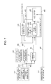
- FIG. 7 is a schematic configuration diagram for describing an example configuration of an encoder according to a second exemplary embodiment of the present invention.
- FIG. 8 is a signal waveform diagram of the encoder according to the second exemplary embodiment of the present invention.
- FIG. 9 is an explanatory diagram for describing an example configuration of an encoder according to a third exemplary embodiment of the present invention.
- FIGS. 10A to 10C are explanatory diagrams for describing an origin signal detection unit and an orthogonal signal detection unit of the encoder according to the third exemplary embodiment of the present invention.
- FIG. 11 is an explanatory diagram for describing a counter reset signal of the encoder according to the third exemplary embodiment of the present invention.
- FIG. 12 is a block diagram for describing an example configuration of an encoder controller according to the third exemplary embodiment of the present invention.
- FIG. 13 is an explanatory diagram for describing the counter reset signal according to the third exemplary embodiment of the present invention.
- FIG. 14 is an explanatory diagram for describing an origin detection sequence of an encoder according to a fourth exemplary embodiment of the present invention.
- FIG. 15 is an explanatory diagram for describing a counter reset signal of the encoder according to the fifth exemplary embodiment of the present invention.
- FIG. 16 is a block diagram for describing an example configuration of an encoder controller according to the fifth exemplary embodiment of the present invention.
- FIG. 17 is an explanatory diagram for describing a counter reset signal of an encoder according to a sixth exemplary embodiment of the present invention.
- FIG. 18 is an explanatory diagram for describing a counter reset signal of an encoder according to a seventh exemplary embodiment of the present invention.
- FIG. 19 is an explanatory diagram for describing a counter reset signal of an encoder according to an eighth exemplary embodiment of the present invention.
- An encoder determines an origin from a plurality of origin candidate signals which are generated in accordance with a position or an angle of a movable body from an orthogonal signal by detecting a reference position signal in a case where the movable body is at a predetermined position.
- the encoder includes a counter configured to reset a counted value of an incremental signal by the origin candidate signals, so that high-speed origin detection can be performed, and it is also possible to provide an origin reset method for an encoder with which origin reset can be performed at a high speed.
- FIG. 5 a scale 101 and a reference position signal pattern 102 configured to generate a reference position signal are illustrated.
- a non-reflective section 106 that is a part of the reference position signal pattern and a reflective section 107 that is similarly a part of the reference position signal pattern are also illustrated.
- An orthogonal signal pattern 103 in which a bright and dark pattern used to generate an orthogonal signal is formed, a bright section 104 that is a part of the orthogonal signal pattern, and a dark section 105 that is also a part of the orthogonal signal pattern are also illustrated.
- a signal reading head 110 an orthogonal signal detection unit (orthogonal signal generation unit configured to generate an orthogonal signal in accordance with a displacement of a position or an angle of a movable body) 111 , and a reference position signal detection unit (reference position detection unit configured to detect a reference position signal in a case where the movable body is at a predetermined position) 112 are also illustrated.
- orthogonal signal detection unit orthogonal signal generation unit configured to generate an orthogonal signal in accordance with a displacement of a position or an angle of a movable body
- reference position signal detection unit reference position detection unit configured to detect a reference position signal in a case where the movable body is at a predetermined position
- the scale 101 is fixed, and the signal reading head 110 is fixed to a carriage (movable body) 141 functioning as a movable part.
- a carriage (movable body) 141 functioning as a movable part.
- a part (not illustrated) can be mounted on the carriage 141 , and the carriage 141 can be moved by an actuator 143 via a guide rail 142 in an X direction.
- An encoder controller 420 includes an orthogonal signal pulse wave generation unit.
- the encoder controller 420 may be provided with a comparison unit 421 , a ⁇ CZ counter 422 , a current position generation unit 423 in addition to an A-phase pulse wave generation unit and a B-phase pulse wave generation unit corresponding to an incremental signal generation unit (orthogonal encoder) in FIG. 1 , which will be described below.
- the signal reading head 110 is electrically connected to the encoder controller 420 and connected to a stage controller 144 via the cable 132 , and the actuator 143 is driven on the basis of a controlled driving current from the stage controller 144 .
- Operating limit positions 120 and 121 of the signal reading head 110 are also illustrated.
- a reference position 122 serves as a boundary position between the non-reflective section 106 and the reflective section 107 of the reference position signal pattern 102 .
- a configuration is adopted in which a cable 132 is arranged inside Cableveyor (registered trademark) 133 , and even when the carriage 141 is moved, an encoder controller 134 and the stage controller 144 can keep a connected state.
- FIG. 6A is a schematic diagram for describing a reading unit for the reference position signal pattern.
- Light emitted from a light source 201 provided to irradiate the scale 101 with light is reflected by the scale 101 and introduced to a detector 204 by a lens 203 or another appropriate optical part, and the detector 204 outputs the size of the quantity of the introduced light as a voltage.
- a reference position signal 404 is output when a voltage 205 from the detector 204 reaches a certain threshold 208 .
- the reference position signal 404 is output when the voltage 205 from the detector 204 reaches the certain threshold 208 as described above, a temporal delay derived from a response time of a photodiode 209 is caused.
- FIG. 2 will be described.
- An A-phase voltage 401 and a B-phase voltage 402 of an orthogonal signal from the orthogonal signal detection unit 111 in the signal reading head 110 in FIG. 5 are illustrated.
- the reference position signal 404 corresponding to 1 is output, and in a case where the voltage 205 is lower than the threshold 208 , the reference position signal 404 corresponding to 0 is output.
- a C-phase voltage 405 is generated on the basis of a voltage magnitude relationship based on a phase change in the A-phase voltage 401 and the B-phase voltage 402 .
- the C-phase voltage 405 is generated by the comparison unit 421 illustrated in FIG. 1 .
- the comparison unit 421 is provided with a comparator 427 and a latch circuit, and the C-phase voltage 405 is generated by a circuit using the comparator 427 .
- Timings for waveform rising and falling of the C-phase voltage 405 require real-time properties with respect to detection of a voltage magnitude relationship of the A-phase voltage 401 and the B-phase voltage 402 , and therefore, analog circuit detection by a comparator circuit is preferably employed.
- A-phase voltage 401 and the B-phase voltage 402 form a continuous sine waveform following the change in the relative position of the signal reading head 110 and the scale 101 , a square wave is also continuously generated in the C-phase voltage 405 .
- the C-phase voltage 405 is generated by the magnitude relationship of the potential difference between the A-phase voltage 401 and the B-phase voltage 402 , but the configuration is not limited to this method.
- the C-phase voltage 405 may be generated by comparison of the A-phase voltage 401 and an arbitrary DC voltage.
- the C-phase voltage 405 may be generated by comparison of the B-phase voltage 402 and an arbitrary DC voltage.
- the A-phase voltage 401 is illustrated as the waveform with a phase leading that of the B-phase voltage 402 by 90 degrees, but the B-phase voltage 402 may have a waveform with a phase leading that of the A-phase voltage 401 by 90 degrees.
- the phase relationship between the A-phase voltage 401 and the B-phase voltage 402 is a positive direction movement in a case where the A-phase voltage 401 leads the B-phase voltage 402 by 90 degrees and is a negative direction movement in a case where the B-phase voltage 402 leads the A-phase voltage 401 by 90 degrees on the basis of a sign of a relative movement direction of the scale 101 and the signal reading head 110 .
- a C1-phase signal 406 is generated as a pulse waveform by using the latch circuit at the time of a waveform rising event of the C-phase voltage 405 , and a timing when the above-described pulse waveform rises is set as an origin candidate signal 407 .
- a voltage waveform of the C-phase voltage 405 is a continuous square wave following the change in the relative position of the signal reading head 110 and the scale 101 .
- a plurality of origin candidate signals 407 can be generated as the C1-phase signals 406 by a circuit using the comparator 427 (origin candidate signal generation unit configured to generate a plurality of origin candidate signals in accordance with the position or the angle of the movable body from the orthogonal signal).
- the origin candidate signals 407 are generated at the time of the event of the rising of the C-phase voltage 405 , but the configuration is not limited to this.
- the origin candidate signals 407 may be generated at the time of an event of falling of the C-phase voltage 405 .
- An incremental count 410 is counted by an incremental counter formed in an incremental signal generation unit (orthogonal encoder) in the encoder controller 420 .
- an A-phase pulse wave 408 and a B-phase pulse wave 409 are generated so as to have a 90-degree phase difference in accordance with a sign of the relative movement direction of the scale 101 and the signal reading head 110 and generated in conformity to the phase relationship between the A-phase voltage 401 and the B-phase voltage 402 .
- the configuration is adopted in which, when the A-phase voltage 401 and the B-phase voltage 402 complete 360-degree phase rotations, the A-phase pulse wave 408 and the B-phase pulse wave 409 output 6 square waves each, and 24 of the incremental counts 410 are counted, but this configuration is an example, and the numbers are not limited to the above.
- This delay occurs because the detection element and the waveform generation circuit are different from each other since the orthogonal signal detection unit 111 and the reference position signal detection unit 112 output waveforms used for different purposes.
- a falling edge of the Z-phase signal has a response time delay of approximately 80 ⁇ sec on average.
- the A-phase voltage 401 and the B-phase voltage 402 which are from the orthogonal signal detection unit 111 are both connected to the encoder controller 420 and the comparison unit 421 .
- the comparison unit 421 outputs the C1-phase signal 406 by the above-described circuit using the comparator 427 and the latch circuit 428 described above by using FIG. 4 , to be connected to the ⁇ CZ counter 422 .
- the A-phase pulse wave 408 and the B-phase pulse wave 409 which are output from the orthogonal signal pulse wave generation unit of the encoder controller 420 are both connected to the ⁇ CZ counter 422 and the current position generation unit 423 .
- the reference position signal 404 output by the reference position signal detection unit 112 is connected to the ⁇ CZ counter 422 .
- the presence or absence of the origin candidate signal 407 in the C1-phase signal 406 is determined. According to the present exemplary embodiment, the determination is made upon the rising event of the origin candidate signal 407 by the origin signal generation unit configured to generate the origin from the plurality of origin candidate signals on the basis of the reference position signal.
- the ⁇ CZ counter since the above-described ⁇ CZ counter is reset each time the origin candidate signal is detected, it is sufficient if the ⁇ CZ counter can count up to 24 counts.
- a reference position signal 404 a is a waveform in a case where the relative movement speed of the signal reading head 110 and the scale 101 is sufficiently low. According to the present exemplary embodiment, a detection position of the reference position signal 404 a is detected at the ninth count when counting is performed by using the incremental count 410 from the most recent origin candidate signal 407 .
- the above-described detection position of the reference position signal 404 a has an error due to a pattern preparation accuracy of the scale 101 , a mounting position accuracy of the orthogonal signal detection unit 111 and the reference position signal detection unit 112 arranged inside the signal reading head 110 , and a gradient accuracy in the apparatus mounting of the signal reading head 110 and the scale 101 . Therefore, individual differences in terms of the individual encoder configurations exist.
- a ⁇ CZ value 412 corresponding to the difference in the incremental count 410 between the origin candidate signal 407 obtained at the time of the detection of the reference position signal 404 as described above and the reference position signal 404 and an origin signal 411 are output to the current position generation unit 423 .
- the current position generation unit 423 counts the incremental count 410 by another counter (incremental counter formed in the orthogonal encoder), which is different from the ⁇ CZ counter, on the basis of the A-phase pulse wave 408 and the B-phase pulse wave 409 .
- the relative movement speed of the signal reading head 110 and the scale 101 is increased to such a relative movement speed that a rising edge of a reference position signal 404 b is detected between the most recent origin candidate signal 407 in a case where the above-described relative movement speed is sufficiently low and the next origin candidate signal 407 after this most recent origin candidate signal 407 .
- a detection position of the reference position signal 404 b is detected at the 22nd count when counting is performed by using the incremental count 410 provided to the ⁇ CZ counter 422 from the most recent origin candidate signal 407 .
- the example using the optical encoder has been described, but the configuration is not limited to the optical encoder.
- a magnetic encoder may be used.
- the same origin 413 is to be set.
- the relative movement speed of the signal reading head 110 and the scale 101 is a relative movement speed in a range where the reference position signal 404 a and the reference position signal 404 b are detected by a timing ⁇ 3 ( 416 ) at which the next origin candidate signal 407 after the A-phase voltage 401 and the B-phase voltage 402 complete the 360-degree phase rotation is detected after the origin candidate signal 407 in the origin 413 is detected.
- the configuration according to the first exemplary embodiment has the following problem derived from the individual differences of the encoder configurations.
- the detection position of the reference position signal 404 a has an error due to the following respective accuracies.
- the error occurs because of the pattern preparation accuracy of the scale 101 , the mounting position accuracy of the orthogonal signal detection unit 111 and the reference position signal detection unit 112 arranged inside the signal reading head 110 , the gradient accuracy in the apparatus mounting of the signal reading head 110 and the scale 101 , and the like. For this reason, the individual differences in terms of the individual encoder configurations exist.
- the reference position signal 404 a and the reference position signal 404 b are to have the same origin candidate signal 407 . For that reason, a problem occurs that the same relative movement speed as the other individual piece may not to be used depending on a combination of the signal reading head 110 and the scale 101 .
- a difference of the present exemplary embodiment resides in that the ⁇ CZ counter 422 in the configuration described according to the first exemplary embodiment is replaced by an origin signal generation unit 425 .
- the origin signal generation unit 425 is provided with the ⁇ CZ counter 422 , a memory 426 that stores a phase correction value, and a phase converter 424 configured to output the C1-phase signal 406 as an origin candidate signal 2 ( 417 ) in which the phase is shifted to an arbitrary shift by the above-described phase correction value.
- the phase converter 424 performs counting until the incremental count 410 reaches the phase correction value and outputs an origin candidate 2 ( 418 ).
- the origin candidate signal 407 in the C1-phase signal 406 is generated each time the incremental count 410 reaches 24 counts. For this reason, the phase correction value is set as 24 counts or lower.
- the phase correction value is obtained by an actual measurement when the apparatus is started to be used.
- the memory 426 has a configuration using a non-volatile memory such that once setting is made, re-setting is not required after turning a main power supply ON and OFF, but the configuration is not limited to this.
- a shift of the detection position occurs in proportion to the increase in the speed as represented by a reference position signal 404 d.
- a detection position of the reference position signal 404 d is detected at the 19th count when counting is performed from the most recent origin candidate 2 ( 418 ) by using the incremental count 410 provided in the ⁇ CZ counter 422 .
- the example using the optical encoder has been described, but the configuration is not limited to the optical encoder.
- a magnetic encoder may be used.
- um represents a millionth of 1 m
- us represents a millionth of 1 second.
- a scale 2101 , a reference position signal pattern 2102 , and an orthogonal signal pattern 2103 are illustrated.
- a non-reflective section 2106 that is a part of the reference position signal pattern 2102 and a reflective section 2107 that is a part of the reference position signal pattern 2102 also illustrated.
- a non-reflective section 2104 that is a part of the orthogonal signal pattern 2103 and a reflective section 2105 that is a part of the orthogonal signal pattern 2103 are also illustrated.
- the orthogonal signal pattern 2103 repeats the same pattern every ⁇ [m].
- a boundary portion 2122 is at between the non-reflective section 2106 and the reflective section 2107 of the reference position signal pattern 2102 .
- a signal reading head 2110 an orthogonal signal detection unit 2111 (position signal generation unit configured to generate an orthogonal signal in accordance with a displacement of a position or an angle of the movable body), and a reference position signal detection unit (origin detection unit configured to generate an origin signal in a case where the movable body is at a predetermined position) 2112 are illustrated.
- position signal generation unit configured to generate an orthogonal signal in accordance with a displacement of a position or an angle of the movable body
- a reference position signal detection unit oil detection unit configured to generate an origin signal in a case where the movable body is at a predetermined position
- a linear guide 2142 is fixed onto a stand 2140 .
- the signal reading head (movable body) 2110 , a slider (movable body) 2141 that moves on the linear guide 2142 , and the slider 2141 and the signal reading head 2110 are connected to each other.
- the scale 2101 is fixed to the stand 2140 .
- a motor 2143 is coupled to the slider 2141 by a ball screw and a guide block that moves on the ball screw which are not illustrated in the drawing, and a rotational motion of the motor 2143 is converted into a linear motion of the slider 2141 .
- An encoder controller 2134 is connected to the orthogonal signal detection unit 2111 and the reference position signal detection unit 2112 .
- the encoder controller 2134 includes an orthogonal encoder 2401 , a speed calculation unit 2403 , a memory 2406 , a reset signal generation unit 2405 , and a current position generation unit 2409 .
- the encoder controller 2134 is configured to generate a current position counter 2303 , a speed excess signal 2408 , and a Z-phase detection signal 2411 .
- a stage controller 2144 is connected to the motor 2143 and the encoder controller 2134 and moves the slider 2141 to a desired position.
- a cable 2132 is arranged inside Cableveyor (registered trademark) 2133 , and even when the slider 2141 is moved, the encoder controller 2134 and the stage controller 2144 can keep a connected state.
- stage controller 2144 Since the stage controller 2144 has a function of rotating the motor 2143 at a predetermined revolution in an arbitrary direction, it is possible to drive the slider 2141 in a positive direction or a negative direction at a substantially constant speed.
- a direction in which the slider 2141 is guided is set as an X axis, and a direction of an arrow is set as a positive direction.
- FIG. 10A is a schematic diagram for describing the reference position signal detection unit 2112 and the orthogonal signal detection unit 2111 .
- Illumination light 2202 from a light source 2201 is reflected by the reference position signal pattern 2102 , and its reflected light 2210 is introduced to the reference position signal detection unit 2112 by a lens 2203 or another appropriate optical element to generate a Z-phase 2207 .
- FIG. 10C is a schematic diagram for describing the reference position signal detection unit 2112 .
- the reflected light 2210 is received by a phototransistor 2219 , and a generated voltage 2205 is compared with a reference voltage 2208 by a comparator 2220 and taken out as the digitalized Z-phase 2207 .
- the Z-phase 2207 is configured to output 0 when the reflected light 2210 is reflected by the non-reflective section 2106 and output 1 when the reflected light 2210 is reflected by the reflective section 2107 .
- FIG. 10B is a schematic diagram for describing the Z-phase 2207 when the slider 2141 moves in the positive direction through the boundary portion 2122 .
- the Z-phase 2207 changes from 0 to 1.
- This position where the Z-phase 2207 changes is set as a Z-phase detection position (Zv), and a speed thereof is set as a Z-phase detection speed (Vz).
- the illumination light 2202 from the light source 2201 is reflected by the orthogonal signal pattern 2103 , and its reflected light 2213 is introduced to the orthogonal signal detection unit 2111 by the lens 2203 or another appropriate optical element to generate AB-phases 2212 .
- a circuit in the related art is used as the circuit that generates the AB-phases 2212 .
- the slider 2141 starts driving from a reference position detection start position 2120 , passes through the boundary portion 2122 , and travels to a reference position detection end position 2121 to stop, and an arbitrary speed can be selected for the speed at which the slider 2141 passes through the boundary portion 2122 (the Z-phase detection speed (Vz)).
- the series of driving corresponds to the origin detection sequence.
- the position of the slider 2141 is not confirmed at the reference position detection start position 2120 , but when the slider 2141 passes through the boundary portion 2122 , the position of the slider 2141 is initialized at a certain position, it is possible to accurately supply the position of the slider 2141 thereafter.
- phase functioning as a reference of this orthogonal signal is a phase in which voltages of the AB-phases are equally positive and is set as an origin candidate signal (phase).
- the origin candidate signal (phase) immediately after the Z-phase 2207 is detected is set as an origin signal (phase) 2306 b.
- a C-phase 2305 is a digital signal that is output by comparing the voltages of the AB-phases 2212 to each other and outputs 0 when the A-phase voltage is lower than the B-phase voltage and outputs 1 when A-phase voltage is higher than the B-phase voltage.
- a relationship between the Z-phase 2207 and the origin detection speed (Vz) will be described.
- the Z-phase 2207 in a case where the origin detection speed (Vz) is sufficiently low is denoted by 2207 a
- the Z-phase 2207 in a case where the origin detection speed (Vz) is not sufficiently low (V1) is denoted by 2207 b .
- Respective phases of the Z-phase detection position (Zv) are denoted by ⁇ a and ⁇ b.
- the response time of the reference position signal detection unit 2112 refers to a time from the light irradiation on the reference position signal detection unit 2112 from the reflective section 2107 until the Z-phase signal 2207 turns to 1.
- This time is mainly determined by response times of the phototransistor 2219 and the comparator 2220 .
- the response time of the orthogonal signal detection unit 2111 refers to a time from the projection of the orthogonal signal pattern 2103 on the orthogonal signal detection unit 2111 until the AB-phases 2212 or the orthogonal signal set to have a higher resolution by phase division from the AB-phases 2212 is output.
- the orthogonal signal detection unit 2111 and the response time of the reference position signal detection unit 2112 are different from each other in general, and when the reference position detection speed (Vz) is changed, the Z-phase detection position (Zv) is also changed.
- the response times can be obtained from data sheets of the elements and experiments.
- FIG. 11 illustrates a case where ⁇ Z is larger than ⁇ AB.
- the current position counter 2303 is reset by the origin signal 2306 b corresponding to the same origin candidate signal (phase) every time, and it is therefore possible to calculate the current position (origin) at a satisfactory reproducibility.
- FIG. 12 is a block diagram for describing a configuration of the encoder controller 2134 .
- an orthogonal encoder 2401 constitutes an incremental signal generation unit configured to generate an incremental signal of a position or an angle from the orthogonal signal, and the AB-phases 2212 are converted into the incremental signal 2402 by the orthogonal encoder 2401 .
- the incremental signal 2402 is input to the speed calculation unit 2403 to generate a speed signal 2404 .
- this speed calculation unit it is possible to determine an excess of a threshold, which will be described next, from the speed at the time of the detection of the origin candidate signal which is obtained from the orthogonal signal.
- a memory (storage unit) 2406 holds a unique origin signal (phase) and the like.
- the reset signal generation unit 2405 generates the counter reset signal 2302 from the speed signal 2404 and the phase ( ⁇ a) stored in the memory 2406 and also generates the speed excess signal 2408 by a speed excess signal generation unit formed in the reset signal generation unit.
- the reset signal generation unit 2405 further generates a Z-phase detection signal 2411 .
- the Z-phase detection signal 2411 becomes effective when the Z-phase detection position (Zv) is detected.
- a current position generation unit 2409 counts the incremental signals 2402 after the counter reset signal 2302 is input therein and generates a current position counter (N).
- the reset signal generation unit 2405 will be described in FIG. 13 .
- the AB-phases 2212 are input to the comparator to generate the C-phase 2305 .
- the C-phase 2305 is input to an AND circuit with the Z-phase 2207 and further passes through the latch circuit, so that the counter reset signal 2302 is generated.
- the current position counter 2303 can be initialized by the origin signal (phase) 2306 b corresponding to the same origin candidate signal (phase) even when the reference position detection speed (Vz) is changed, and it is therefore possible to accurately calculate the current position (origin).
- the current position counter can be accurately output. Even in a case where the reference position detection signal (phase) ( ⁇ b) skips the origin signal (phase) 2306 b , it is possible to detect the excess by the speed excess signal 2408 . Thus, it is possible to avoid the driving based on the erroneous position information thereafter.
- V0 is set as an initial value of the Z-phase detection speed (Vz), and the Z-phase detection sequence is performed in 2602 .
- the Z-phase detection speed is multiplied by K (K ⁇ 1) in 2604 , and while the Z-phase detection sequence is repeatedly performed again, the process can be ended when the speed is decreased so as not to be determined as the speed excess (NO in 2603 ).
- FIG. 15 and FIG. 16 An example configuration according to a fifth exemplary embodiment will be described by using FIG. 15 and FIG. 16 .
- FIG. 15 is an explanatory diagram for describing a case where the Z-phase detection position is beyond the origin signal (phase) 2306 b.
- the Z-phase 2207 turns to 2207 c , and the Z-phase detection position is at a position ⁇ c skipping the origin signal (phase) 2306 b.
- the counter is initialized by an origin signal (phase) ( 2306 c ) corresponding to an origin candidate signal immediately after ⁇ c, and when counts equivalent to ⁇ are added to the current position counter, it is possible to accurately calculate the current position (origin) similarly as in the case where the current position counter is initialized by the origin signal (phase) 2306 b.
- FIG. 16 is a block diagram for describing an example configuration of the encoder controller 2134 according to the fifth exemplary embodiment.
- the speed excess signal 2408 is deleted, and an offset amount 2801 is added as compared with FIG. 12 .
- the current position generation unit 2409 outputs the current position counter 2303 b obtained by adding M*N ⁇ to the current position counter 2303 that integrates the incremental signals 2402 .
- FIG. 17 An example configuration according to a sixth exemplary embodiment will be described by using FIG. 17 .
- FIG. 17 schematically represents a case where the Z-phase detection position ( ⁇ d) is in the vicinity of the origin signal (phase) 2306 b.
- the current position counter is initialized by a different phase by ⁇ [rad] from the origin signal (phase).
- FIG. 18 An example configuration according to a seventh exemplary embodiment will be described by using FIG. 18 .
- FIG. 18 schematically represents a case where the size of ⁇ AB*Vz is large enough to be non-negligible to a required measurement accuracy.
- a C-phase signal to be electrically output is denoted by 2305
- a C-phase signal in a case where ⁇ AB is supposed to be 0 is set as C′-phase 2308 .
- FIG. 18 illustrates a case where the C-phase signal should be output at the original phase ⁇ e but is output at a phase ⁇ f since ⁇ AB*Vz is large.
- errors equivalent to two counts 2308 a and 2308 b ) occur.
- the current position counter may be set as a predetermined value by the C-phase signal until Vz becomes small, that is, the speed of the slider is decreased to a sufficiently low speed.
- the error 2308 a exists at the time of the first C-phase detection after a Z-phase 2207 e is detected. However, when the speed is decreased, the error is reduced to a level of the error 2308 b ( ⁇ g, ⁇ h) at the time of the second C-phase detection, and at the time immediately before the stop, the error is reduced to a level of an error 2308 c that is negligible ( ⁇ i, ⁇ j).
- FIG. 19 An example configuration according to an eighth exemplary embodiment will be described by using FIG. 19 .
- the configurations similar to those of FIG. 15 are assigned with the same reference numerals, and descriptions thereof will be omitted.
- a counter that is continuously counted is set as QPOSCNT, QPOSCNT at a time when the Z-phase ( 2207 C) is detected is set as Qz, and QPOSCNT at a time when the C-phase ( 2302 C) is detected is set as Qc.
- K is a constant determined by sizes of fluctuations of ⁇ Z and ⁇ AB and a calculation error of Vz, and a representative constant is approximately 0.2.
- the encoder that can perform the stable origin detection even in a case where the origin detection is detected at a relatively high speed and the origin calculation method for the encoder with which the accurate origin calculation can be performed.
Landscapes
- Engineering & Computer Science (AREA)
- Signal Processing (AREA)
- Physics & Mathematics (AREA)
- General Physics & Mathematics (AREA)
- Optical Transform (AREA)
- Transmission And Conversion Of Sensor Element Output (AREA)
Abstract
Description
Δθ=((τZ−τAB)/λ)*2π*
τZ−τAB=100 us
Vz=0.5 m/s Expression 3; and
λ=80
θa and θb are different in distance after conversion from each other by approximately
100 us*0.5 m/s=50 um.
2π≦θa+((τZ−τAB)/λ)*2π*
(2+2M)π≦θa+((τZ−τAB)/λ)*2π*Vz<(4+2M)π Expression 6,
while a current position is represented by pos, and a counted value equivalent to λ is set as Nλ, pos can be calculated by the following expression:
pos=N+M*Nλ Expression 7.
(1+2M)π≦θa+((τZ−τAB)/λ)*2π*Vz<(3+2M)π Expression 8; and
pos=N+(M+½)*Nλ Expression 9.
pos=Nc*Nλ+n Expression 10.
Qz0=Qz−(τZ−τAB)*Vz/ΔX Expression 11.
dZ=K*(τZ−τAB)*Vz/ΔX Expression 12;
Qz0p=Qz0+dZ Expression 13; and
Qz0m=Qz0−dZ Expression 14.
Qz0m≦Qc−Nλ*M+θa<Qz0p Expression 15.
pos=N+M*Nλ Expression 16
where 0≦K<1.
Claims (11)
Applications Claiming Priority (4)
| Application Number | Priority Date | Filing Date | Title |
|---|---|---|---|
| JP2013-169806 | 2013-08-19 | ||
| JP2013169806A JP6234111B2 (en) | 2013-08-19 | 2013-08-19 | Encoder and encoder origin reset method |
| JP2013-181856 | 2013-09-03 | ||
| JP2013181856 | 2013-09-03 |
Publications (2)
| Publication Number | Publication Date |
|---|---|
| US20150049596A1 US20150049596A1 (en) | 2015-02-19 |
| US9484060B2 true US9484060B2 (en) | 2016-11-01 |
Family
ID=51389950
Family Applications (1)
| Application Number | Title | Priority Date | Filing Date |
|---|---|---|---|
| US14/461,235 Expired - Fee Related US9484060B2 (en) | 2013-08-19 | 2014-08-15 | Encoder |
Country Status (3)
| Country | Link |
|---|---|
| US (1) | US9484060B2 (en) |
| EP (1) | EP2840361B1 (en) |
| CN (1) | CN104422468B (en) |
Cited By (1)
| Publication number | Priority date | Publication date | Assignee | Title |
|---|---|---|---|---|
| US20150365103A1 (en) * | 2013-01-18 | 2015-12-17 | Otis Elevator Company | Encoder resolution reduction |
Families Citing this family (3)
| Publication number | Priority date | Publication date | Assignee | Title |
|---|---|---|---|---|
| CN106272430B (en) * | 2016-09-18 | 2018-12-07 | 珠海格力电器股份有限公司 | Manipulator origin resetting method and device |
| CN109844462B (en) * | 2016-10-25 | 2021-05-25 | 三菱电机株式会社 | Pulse conversion device and pulse conversion method for incremental encoder |
| CN115400887B (en) * | 2021-05-28 | 2025-02-14 | 青岛海特生物医疗有限公司 | Method and system for centrifuge rotor identification |
Citations (13)
| Publication number | Priority date | Publication date | Assignee | Title |
|---|---|---|---|---|
| US4774446A (en) * | 1984-10-04 | 1988-09-27 | Pitney Bowes Inc. | Microprocessor controlled d.c. motor for controlling printing means |
| US4803354A (en) * | 1986-04-09 | 1989-02-07 | Hitachi Medical Corp. | Circuit for correcting output phase of rotary encoder |
| US5021781A (en) * | 1989-10-18 | 1991-06-04 | Pitney Bowes Inc. | Two stage quadrature incremental encoder |
| US5210562A (en) * | 1990-09-17 | 1993-05-11 | Olympus Optical Co., Ltd. | Motor driving control apparatus with movement distance estimating function |
| US5331262A (en) * | 1992-12-09 | 1994-07-19 | Pitney Bowes Inc. | Self adjusting motor positioning system and method |
| US6407683B1 (en) * | 2000-07-27 | 2002-06-18 | Tyco Electronics Logistics Ag | Optimized performance incremental encoder with error detection capability |
| US20030052287A1 (en) | 2001-07-03 | 2003-03-20 | Akihiro Iino | Electronic equipment equipped with position detection means |
| US7091884B2 (en) * | 2003-09-26 | 2006-08-15 | Hewlett-Packard Development Company, L.P. | Analog position encoder |
| US7375487B2 (en) * | 2005-02-28 | 2008-05-20 | Harmonic Drive Systems Inc. | Geared motor |
| JP4274751B2 (en) | 2001-07-03 | 2009-06-10 | オリンパス株式会社 | Encoder |
| US20100072348A1 (en) | 2008-09-19 | 2010-03-25 | Mitutoyo Corporation | Optical encoder |
| US7994749B2 (en) * | 2005-10-18 | 2011-08-09 | Harmonic Drive Systems Inc. | Multiple-rotation absolute-value encoder of geared motor |
| US8587170B2 (en) * | 2008-05-21 | 2013-11-19 | Siemens Industry, Inc. | Actuator arrangement with worm gear and rotational output having an encoder |
Family Cites Families (3)
| Publication number | Priority date | Publication date | Assignee | Title |
|---|---|---|---|---|
| JP2660006B2 (en) * | 1988-07-26 | 1997-10-08 | ファナック株式会社 | Rotor angle detection method |
| JPH08178700A (en) * | 1994-12-22 | 1996-07-12 | Topcon Corp | Incremental encoder |
| JP4953589B2 (en) * | 2005-05-25 | 2012-06-13 | 株式会社ミツトヨ | Method and apparatus for generating origin signal of encoder |
-
2014
- 2014-08-15 US US14/461,235 patent/US9484060B2/en not_active Expired - Fee Related
- 2014-08-19 CN CN201410408010.9A patent/CN104422468B/en not_active Expired - Fee Related
- 2014-08-19 EP EP14181442.6A patent/EP2840361B1/en not_active Not-in-force
Patent Citations (15)
| Publication number | Priority date | Publication date | Assignee | Title |
|---|---|---|---|---|
| US4774446A (en) * | 1984-10-04 | 1988-09-27 | Pitney Bowes Inc. | Microprocessor controlled d.c. motor for controlling printing means |
| US4803354A (en) * | 1986-04-09 | 1989-02-07 | Hitachi Medical Corp. | Circuit for correcting output phase of rotary encoder |
| US5021781A (en) * | 1989-10-18 | 1991-06-04 | Pitney Bowes Inc. | Two stage quadrature incremental encoder |
| US5210562A (en) * | 1990-09-17 | 1993-05-11 | Olympus Optical Co., Ltd. | Motor driving control apparatus with movement distance estimating function |
| US5331262A (en) * | 1992-12-09 | 1994-07-19 | Pitney Bowes Inc. | Self adjusting motor positioning system and method |
| US6407683B1 (en) * | 2000-07-27 | 2002-06-18 | Tyco Electronics Logistics Ag | Optimized performance incremental encoder with error detection capability |
| US20030052287A1 (en) | 2001-07-03 | 2003-03-20 | Akihiro Iino | Electronic equipment equipped with position detection means |
| US6917034B2 (en) * | 2001-07-03 | 2005-07-12 | Seiko Instruments Inc. | Electronic equipment equipped with position detection means for detecting position of moving body utilizing incremental-type encoder |
| JP4274751B2 (en) | 2001-07-03 | 2009-06-10 | オリンパス株式会社 | Encoder |
| US7091884B2 (en) * | 2003-09-26 | 2006-08-15 | Hewlett-Packard Development Company, L.P. | Analog position encoder |
| US7375487B2 (en) * | 2005-02-28 | 2008-05-20 | Harmonic Drive Systems Inc. | Geared motor |
| US7994749B2 (en) * | 2005-10-18 | 2011-08-09 | Harmonic Drive Systems Inc. | Multiple-rotation absolute-value encoder of geared motor |
| US8587170B2 (en) * | 2008-05-21 | 2013-11-19 | Siemens Industry, Inc. | Actuator arrangement with worm gear and rotational output having an encoder |
| US20100072348A1 (en) | 2008-09-19 | 2010-03-25 | Mitutoyo Corporation | Optical encoder |
| US8173951B2 (en) * | 2008-09-19 | 2012-05-08 | Mitutoyo Corporation | Optical encoder comprising a main and reference light receiving portions with a three-phase signal generation for detecting displacement and direction of displacement of an incremental grating track |
Cited By (2)
| Publication number | Priority date | Publication date | Assignee | Title |
|---|---|---|---|---|
| US20150365103A1 (en) * | 2013-01-18 | 2015-12-17 | Otis Elevator Company | Encoder resolution reduction |
| US9979412B2 (en) * | 2013-01-18 | 2018-05-22 | Otis Elevator Company | Encoder resolution reduction |
Also Published As
| Publication number | Publication date |
|---|---|
| CN104422468A (en) | 2015-03-18 |
| US20150049596A1 (en) | 2015-02-19 |
| CN104422468B (en) | 2017-09-29 |
| EP2840361B1 (en) | 2016-06-08 |
| EP2840361A1 (en) | 2015-02-25 |
Similar Documents
| Publication | Publication Date | Title |
|---|---|---|
| US9484060B2 (en) | Encoder | |
| EP2511668B1 (en) | Encoder | |
| US9279703B2 (en) | Encoder and apparatus with the same | |
| TWI485368B (en) | Photosensor for position detecting device, position detecting device using same and position detecting method | |
| US9228857B2 (en) | Position detection apparatus having a determining unit to determine the reliability of calculated position of a movable member | |
| CN107314740B (en) | Position calibration system and calibration method of double-vibrating-mirror scanning system | |
| US20080073493A1 (en) | Origin detection method for optical encoder | |
| US20150130931A1 (en) | Position detecting apparatus, and lens apparatus and image pickup apparatus including the position detecting apparatus | |
| JP6234111B2 (en) | Encoder and encoder origin reset method | |
| JP5490805B2 (en) | Circuit arrangement and method for generating a reference pulse for a position measuring device | |
| US9470880B2 (en) | Position detecting apparatus, and lens apparatus and optical operating apparatus including the position detecting apparatus | |
| CN1924748B (en) | Image pickup device and control method thereof | |
| US7282699B2 (en) | Optical encoder for improved detection of the absolute position of an origin point | |
| US20190196140A1 (en) | Lens barrel controlling linear driving of movable lens and optical apparatus equipped with lens barrel | |
| US8069580B2 (en) | Measuring device for determining a position and/or a speed | |
| US9435667B2 (en) | Position detecting apparatus, and lens apparatus and image pickup apparatus including the position detecting apparatus | |
| US8912793B2 (en) | Linear position measuring system and method for determining the absolute position of a carriage along a slide rail | |
| JP2015072265A (en) | Encoder, and origin calculation method of the same | |
| KR102299626B1 (en) | Batteryless Absolute Encoder | |
| US9041386B2 (en) | Linear position measuring system and method for determining the position of a carriage in relation to a slide rail with an incremental scale placed along the slide rail and a scanner secured to the slide scale | |
| JP3862690B2 (en) | PHASE DETECTION DEVICE, DIAL TYPE DETECTION DEVICE, AND PHASE DETECTION METHOD | |
| JP2007127560A (en) | POSITION DETECTION DEVICE, SCALE, AND POSITION DETECTION METHOD | |
| JP2000298961A (en) | Positioning control device and positioning control method | |
| JP2009065770A (en) | Stepping motor control device |
Legal Events
| Date | Code | Title | Description |
|---|---|---|---|
| AS | Assignment |
Owner name: CANON KABUSHIKI KAISHA, JAPAN Free format text: ASSIGNMENT OF ASSIGNORS INTEREST;ASSIGNORS:YAMAMOTO, TAKESHI;SUZUKI, NORIHIRO;REEL/FRAME:034522/0654 Effective date: 20140804 |
|
| STCF | Information on status: patent grant |
Free format text: PATENTED CASE |
|
| MAFP | Maintenance fee payment |
Free format text: PAYMENT OF MAINTENANCE FEE, 4TH YEAR, LARGE ENTITY (ORIGINAL EVENT CODE: M1551); ENTITY STATUS OF PATENT OWNER: LARGE ENTITY Year of fee payment: 4 |
|
| FEPP | Fee payment procedure |
Free format text: MAINTENANCE FEE REMINDER MAILED (ORIGINAL EVENT CODE: REM.); ENTITY STATUS OF PATENT OWNER: LARGE ENTITY |
|
| LAPS | Lapse for failure to pay maintenance fees |
Free format text: PATENT EXPIRED FOR FAILURE TO PAY MAINTENANCE FEES (ORIGINAL EVENT CODE: EXP.); ENTITY STATUS OF PATENT OWNER: LARGE ENTITY |
|
| STCH | Information on status: patent discontinuation |
Free format text: PATENT EXPIRED DUE TO NONPAYMENT OF MAINTENANCE FEES UNDER 37 CFR 1.362 |
|
| FP | Lapsed due to failure to pay maintenance fee |
Effective date: 20241101 |