US9478779B2 - Cell to cell terminal connections for a high voltage battery - Google Patents
Cell to cell terminal connections for a high voltage battery Download PDFInfo
- Publication number
- US9478779B2 US9478779B2 US14/464,191 US201414464191A US9478779B2 US 9478779 B2 US9478779 B2 US 9478779B2 US 201414464191 A US201414464191 A US 201414464191A US 9478779 B2 US9478779 B2 US 9478779B2
- Authority
- US
- United States
- Prior art keywords
- cells
- terminals
- array
- assembly
- battery
- Prior art date
- Legal status (The legal status is an assumption and is not a legal conclusion. Google has not performed a legal analysis and makes no representation as to the accuracy of the status listed.)
- Active, expires
Links
- 238000003491 array Methods 0.000 claims abstract description 35
- 230000006835 compression Effects 0.000 claims description 10
- 238000007906 compression Methods 0.000 claims description 10
- 239000004020 conductor Substances 0.000 claims description 5
- 239000000615 nonconductor Substances 0.000 claims description 4
- 239000011888 foil Substances 0.000 description 19
- 239000012530 fluid Substances 0.000 description 9
- 238000007726 management method Methods 0.000 description 8
- 238000012546 transfer Methods 0.000 description 8
- 238000004891 communication Methods 0.000 description 6
- 230000005540 biological transmission Effects 0.000 description 4
- 238000006243 chemical reaction Methods 0.000 description 4
- 239000000463 material Substances 0.000 description 3
- 238000004806 packaging method and process Methods 0.000 description 3
- 125000006850 spacer group Chemical group 0.000 description 3
- 239000000446 fuel Substances 0.000 description 2
- 238000010438 heat treatment Methods 0.000 description 2
- 239000007788 liquid Substances 0.000 description 2
- 238000000034 method Methods 0.000 description 2
- 238000003466 welding Methods 0.000 description 2
- 230000015572 biosynthetic process Effects 0.000 description 1
- 230000001010 compromised effect Effects 0.000 description 1
- 230000003750 conditioning effect Effects 0.000 description 1
- 238000001816 cooling Methods 0.000 description 1
- 238000007599 discharging Methods 0.000 description 1
- 238000009826 distribution Methods 0.000 description 1
- 238000010292 electrical insulation Methods 0.000 description 1
- 239000003792 electrolyte Substances 0.000 description 1
- 238000004146 energy storage Methods 0.000 description 1
- 239000003344 environmental pollutant Substances 0.000 description 1
- 150000002500 ions Chemical class 0.000 description 1
- 238000005304 joining Methods 0.000 description 1
- 230000013011 mating Effects 0.000 description 1
- 238000012986 modification Methods 0.000 description 1
- 230000004048 modification Effects 0.000 description 1
- 238000012544 monitoring process Methods 0.000 description 1
- 231100000719 pollutant Toxicity 0.000 description 1
- 230000001172 regenerating effect Effects 0.000 description 1
- 239000000126 substance Substances 0.000 description 1
Images


Classifications
-
- H—ELECTRICITY
- H01—ELECTRIC ELEMENTS
- H01M—PROCESSES OR MEANS, e.g. BATTERIES, FOR THE DIRECT CONVERSION OF CHEMICAL ENERGY INTO ELECTRICAL ENERGY
- H01M10/00—Secondary cells; Manufacture thereof
- H01M10/04—Construction or manufacture in general
- H01M10/0413—Large-sized flat cells or batteries for motive or stationary systems with plate-like electrodes
-
- H01M2/1083—
-
- B—PERFORMING OPERATIONS; TRANSPORTING
- B60—VEHICLES IN GENERAL
- B60L—PROPULSION OF ELECTRICALLY-PROPELLED VEHICLES; SUPPLYING ELECTRIC POWER FOR AUXILIARY EQUIPMENT OF ELECTRICALLY-PROPELLED VEHICLES; ELECTRODYNAMIC BRAKE SYSTEMS FOR VEHICLES IN GENERAL; MAGNETIC SUSPENSION OR LEVITATION FOR VEHICLES; MONITORING OPERATING VARIABLES OF ELECTRICALLY-PROPELLED VEHICLES; ELECTRIC SAFETY DEVICES FOR ELECTRICALLY-PROPELLED VEHICLES
- B60L50/00—Electric propulsion with power supplied within the vehicle
- B60L50/50—Electric propulsion with power supplied within the vehicle using propulsion power supplied by batteries or fuel cells
- B60L50/60—Electric propulsion with power supplied within the vehicle using propulsion power supplied by batteries or fuel cells using power supplied by batteries
- B60L50/64—Constructional details of batteries specially adapted for electric vehicles
-
- H—ELECTRICITY
- H01—ELECTRIC ELEMENTS
- H01M—PROCESSES OR MEANS, e.g. BATTERIES, FOR THE DIRECT CONVERSION OF CHEMICAL ENERGY INTO ELECTRICAL ENERGY
- H01M10/00—Secondary cells; Manufacture thereof
- H01M10/42—Methods or arrangements for servicing or maintenance of secondary cells or secondary half-cells
- H01M10/4207—Methods or arrangements for servicing or maintenance of secondary cells or secondary half-cells for several batteries or cells simultaneously or sequentially
-
- H01M2/1077—
-
- H01M2/22—
-
- H01M2/30—
-
- H—ELECTRICITY
- H01—ELECTRIC ELEMENTS
- H01M—PROCESSES OR MEANS, e.g. BATTERIES, FOR THE DIRECT CONVERSION OF CHEMICAL ENERGY INTO ELECTRICAL ENERGY
- H01M50/00—Constructional details or processes of manufacture of the non-active parts of electrochemical cells other than fuel cells, e.g. hybrid cells
- H01M50/10—Primary casings; Jackets or wrappings
- H01M50/172—Arrangements of electric connectors penetrating the casing
- H01M50/174—Arrangements of electric connectors penetrating the casing adapted for the shape of the cells
- H01M50/176—Arrangements of electric connectors penetrating the casing adapted for the shape of the cells for prismatic or rectangular cells
-
- H—ELECTRICITY
- H01—ELECTRIC ELEMENTS
- H01M—PROCESSES OR MEANS, e.g. BATTERIES, FOR THE DIRECT CONVERSION OF CHEMICAL ENERGY INTO ELECTRICAL ENERGY
- H01M50/00—Constructional details or processes of manufacture of the non-active parts of electrochemical cells other than fuel cells, e.g. hybrid cells
- H01M50/10—Primary casings; Jackets or wrappings
- H01M50/172—Arrangements of electric connectors penetrating the casing
- H01M50/174—Arrangements of electric connectors penetrating the casing adapted for the shape of the cells
- H01M50/178—Arrangements of electric connectors penetrating the casing adapted for the shape of the cells for pouch or flexible bag cells
-
- H—ELECTRICITY
- H01—ELECTRIC ELEMENTS
- H01M—PROCESSES OR MEANS, e.g. BATTERIES, FOR THE DIRECT CONVERSION OF CHEMICAL ENERGY INTO ELECTRICAL ENERGY
- H01M50/00—Constructional details or processes of manufacture of the non-active parts of electrochemical cells other than fuel cells, e.g. hybrid cells
- H01M50/20—Mountings; Secondary casings or frames; Racks, modules or packs; Suspension devices; Shock absorbers; Transport or carrying devices; Holders
- H01M50/204—Racks, modules or packs for multiple batteries or multiple cells
- H01M50/207—Racks, modules or packs for multiple batteries or multiple cells characterised by their shape
- H01M50/209—Racks, modules or packs for multiple batteries or multiple cells characterised by their shape adapted for prismatic or rectangular cells
-
- H—ELECTRICITY
- H01—ELECTRIC ELEMENTS
- H01M—PROCESSES OR MEANS, e.g. BATTERIES, FOR THE DIRECT CONVERSION OF CHEMICAL ENERGY INTO ELECTRICAL ENERGY
- H01M50/00—Constructional details or processes of manufacture of the non-active parts of electrochemical cells other than fuel cells, e.g. hybrid cells
- H01M50/20—Mountings; Secondary casings or frames; Racks, modules or packs; Suspension devices; Shock absorbers; Transport or carrying devices; Holders
- H01M50/204—Racks, modules or packs for multiple batteries or multiple cells
- H01M50/207—Racks, modules or packs for multiple batteries or multiple cells characterised by their shape
- H01M50/211—Racks, modules or packs for multiple batteries or multiple cells characterised by their shape adapted for pouch cells
-
- H—ELECTRICITY
- H01—ELECTRIC ELEMENTS
- H01M—PROCESSES OR MEANS, e.g. BATTERIES, FOR THE DIRECT CONVERSION OF CHEMICAL ENERGY INTO ELECTRICAL ENERGY
- H01M50/00—Constructional details or processes of manufacture of the non-active parts of electrochemical cells other than fuel cells, e.g. hybrid cells
- H01M50/20—Mountings; Secondary casings or frames; Racks, modules or packs; Suspension devices; Shock absorbers; Transport or carrying devices; Holders
- H01M50/249—Mountings; Secondary casings or frames; Racks, modules or packs; Suspension devices; Shock absorbers; Transport or carrying devices; Holders specially adapted for aircraft or vehicles, e.g. cars or trains
-
- H—ELECTRICITY
- H01—ELECTRIC ELEMENTS
- H01M—PROCESSES OR MEANS, e.g. BATTERIES, FOR THE DIRECT CONVERSION OF CHEMICAL ENERGY INTO ELECTRICAL ENERGY
- H01M50/00—Constructional details or processes of manufacture of the non-active parts of electrochemical cells other than fuel cells, e.g. hybrid cells
- H01M50/20—Mountings; Secondary casings or frames; Racks, modules or packs; Suspension devices; Shock absorbers; Transport or carrying devices; Holders
- H01M50/298—Mountings; Secondary casings or frames; Racks, modules or packs; Suspension devices; Shock absorbers; Transport or carrying devices; Holders characterised by the wiring of battery packs
-
- H—ELECTRICITY
- H01—ELECTRIC ELEMENTS
- H01M—PROCESSES OR MEANS, e.g. BATTERIES, FOR THE DIRECT CONVERSION OF CHEMICAL ENERGY INTO ELECTRICAL ENERGY
- H01M50/00—Constructional details or processes of manufacture of the non-active parts of electrochemical cells other than fuel cells, e.g. hybrid cells
- H01M50/50—Current conducting connections for cells or batteries
- H01M50/502—Interconnectors for connecting terminals of adjacent batteries; Interconnectors for connecting cells outside a battery casing
- H01M50/503—Interconnectors for connecting terminals of adjacent batteries; Interconnectors for connecting cells outside a battery casing characterised by the shape of the interconnectors
-
- H—ELECTRICITY
- H01—ELECTRIC ELEMENTS
- H01M—PROCESSES OR MEANS, e.g. BATTERIES, FOR THE DIRECT CONVERSION OF CHEMICAL ENERGY INTO ELECTRICAL ENERGY
- H01M50/00—Constructional details or processes of manufacture of the non-active parts of electrochemical cells other than fuel cells, e.g. hybrid cells
- H01M50/50—Current conducting connections for cells or batteries
- H01M50/502—Interconnectors for connecting terminals of adjacent batteries; Interconnectors for connecting cells outside a battery casing
- H01M50/509—Interconnectors for connecting terminals of adjacent batteries; Interconnectors for connecting cells outside a battery casing characterised by the type of connection, e.g. mixed connections
- H01M50/51—Connection only in series
-
- H—ELECTRICITY
- H01—ELECTRIC ELEMENTS
- H01M—PROCESSES OR MEANS, e.g. BATTERIES, FOR THE DIRECT CONVERSION OF CHEMICAL ENERGY INTO ELECTRICAL ENERGY
- H01M50/00—Constructional details or processes of manufacture of the non-active parts of electrochemical cells other than fuel cells, e.g. hybrid cells
- H01M50/50—Current conducting connections for cells or batteries
- H01M50/502—Interconnectors for connecting terminals of adjacent batteries; Interconnectors for connecting cells outside a battery casing
- H01M50/514—Methods for interconnecting adjacent batteries or cells
-
- H—ELECTRICITY
- H01—ELECTRIC ELEMENTS
- H01M—PROCESSES OR MEANS, e.g. BATTERIES, FOR THE DIRECT CONVERSION OF CHEMICAL ENERGY INTO ELECTRICAL ENERGY
- H01M50/00—Constructional details or processes of manufacture of the non-active parts of electrochemical cells other than fuel cells, e.g. hybrid cells
- H01M50/50—Current conducting connections for cells or batteries
- H01M50/528—Fixed electrical connections, i.e. not intended for disconnection
-
- H—ELECTRICITY
- H01—ELECTRIC ELEMENTS
- H01M—PROCESSES OR MEANS, e.g. BATTERIES, FOR THE DIRECT CONVERSION OF CHEMICAL ENERGY INTO ELECTRICAL ENERGY
- H01M50/00—Constructional details or processes of manufacture of the non-active parts of electrochemical cells other than fuel cells, e.g. hybrid cells
- H01M50/50—Current conducting connections for cells or batteries
- H01M50/543—Terminals
- H01M50/547—Terminals characterised by the disposition of the terminals on the cells
- H01M50/55—Terminals characterised by the disposition of the terminals on the cells on the same side of the cell
-
- H—ELECTRICITY
- H01—ELECTRIC ELEMENTS
- H01M—PROCESSES OR MEANS, e.g. BATTERIES, FOR THE DIRECT CONVERSION OF CHEMICAL ENERGY INTO ELECTRICAL ENERGY
- H01M50/00—Constructional details or processes of manufacture of the non-active parts of electrochemical cells other than fuel cells, e.g. hybrid cells
- H01M50/50—Current conducting connections for cells or batteries
- H01M50/543—Terminals
- H01M50/552—Terminals characterised by their shape
- H01M50/553—Terminals adapted for prismatic, pouch or rectangular cells
-
- H—ELECTRICITY
- H01—ELECTRIC ELEMENTS
- H01M—PROCESSES OR MEANS, e.g. BATTERIES, FOR THE DIRECT CONVERSION OF CHEMICAL ENERGY INTO ELECTRICAL ENERGY
- H01M50/00—Constructional details or processes of manufacture of the non-active parts of electrochemical cells other than fuel cells, e.g. hybrid cells
- H01M50/50—Current conducting connections for cells or batteries
- H01M50/543—Terminals
- H01M50/564—Terminals characterised by their manufacturing process
- H01M50/566—Terminals characterised by their manufacturing process by welding, soldering or brazing
-
- H—ELECTRICITY
- H01—ELECTRIC ELEMENTS
- H01M—PROCESSES OR MEANS, e.g. BATTERIES, FOR THE DIRECT CONVERSION OF CHEMICAL ENERGY INTO ELECTRICAL ENERGY
- H01M2220/00—Batteries for particular applications
- H01M2220/20—Batteries in motive systems, e.g. vehicle, ship, plane
-
- Y—GENERAL TAGGING OF NEW TECHNOLOGICAL DEVELOPMENTS; GENERAL TAGGING OF CROSS-SECTIONAL TECHNOLOGIES SPANNING OVER SEVERAL SECTIONS OF THE IPC; TECHNICAL SUBJECTS COVERED BY FORMER USPC CROSS-REFERENCE ART COLLECTIONS [XRACs] AND DIGESTS
- Y02—TECHNOLOGIES OR APPLICATIONS FOR MITIGATION OR ADAPTATION AGAINST CLIMATE CHANGE
- Y02E—REDUCTION OF GREENHOUSE GAS [GHG] EMISSIONS, RELATED TO ENERGY GENERATION, TRANSMISSION OR DISTRIBUTION
- Y02E60/00—Enabling technologies; Technologies with a potential or indirect contribution to GHG emissions mitigation
- Y02E60/10—Energy storage using batteries
-
- Y—GENERAL TAGGING OF NEW TECHNOLOGICAL DEVELOPMENTS; GENERAL TAGGING OF CROSS-SECTIONAL TECHNOLOGIES SPANNING OVER SEVERAL SECTIONS OF THE IPC; TECHNICAL SUBJECTS COVERED BY FORMER USPC CROSS-REFERENCE ART COLLECTIONS [XRACs] AND DIGESTS
- Y02—TECHNOLOGIES OR APPLICATIONS FOR MITIGATION OR ADAPTATION AGAINST CLIMATE CHANGE
- Y02T—CLIMATE CHANGE MITIGATION TECHNOLOGIES RELATED TO TRANSPORTATION
- Y02T10/00—Road transport of goods or passengers
- Y02T10/60—Other road transportation technologies with climate change mitigation effect
- Y02T10/70—Energy storage systems for electromobility, e.g. batteries
Definitions
- This disclosure relates to battery cell orientations to assist in facilitating electrical connections between battery cell terminals for high voltage batteries utilized in vehicles.
- Vehicles such as battery-electric vehicles (BEVs), plug-in hybrid-electric vehicles (PHEVs), mild hybrid-electric vehicles (MHEVs), or full hybrid-electric vehicles (FHEVs) may contain an energy storage device, such as a high voltage (HV) battery, to act as a propulsion source for the vehicle.
- HV battery may include components and systems to assist in managing vehicle performance and operations.
- the HV battery may include one or more arrays of battery cells interconnected electrically between battery cell terminals and interconnector busbars.
- the HV battery and surrounding environment may include a thermal management system to assist in managing temperature of the HV battery components, systems, and individual battery cells.
- a traction battery assembly includes first and second arrays spaced apart and each having a plurality of prismatic cells each with a positive and a negative terminal on a cell face facing the other array.
- the cells are oriented in tilted stacks such that the terminals of at least one of the cells of the first array are aligned with oppositely charged terminals of two different cells of the second array.
- the assembly may also include a frame supporting and orienting the cells such that the cells of the arrays are tilted at opposing and inversely equal angles which are based on a width and length of each battery cell to facilitate the alignment of the terminals of at least one of the cells of the first array with the oppositely charged terminals of two different cells of the second array.
- the positive and negative terminals may define substantially flat contact surfaces.
- the frame may be configured to apply a lateral compression force against each of the arrays such that the aligned positive and negative terminals at least partially contact one another.
- the terminals may be tabs extending at least partially through planes defined by respective upper and lower faces of the respective cell. The tabs may be joined together.
- At least one of the positive terminals and at least one of the negative terminals at opposite longitudinal ends of the arrays may be in electrical connection with a wire harness or electrical output conductor.
- At least one of the cells of the first array may be tilted at a first angle and the two different cells of the second array may be tilted at a second angle.
- a degree of the first and second angles relative to a vertical axis may be based on a cell width and cell length.
- a traction battery assembly includes first and second arrays each having a plurality of cells with a positive and a negative terminal facing the opposite array.
- the positive terminals of the cells of the first array are located at an upper portion of a cell side face and the negative terminals of the cells of the second array are located at an upper portion of a cell side face.
- the assembly also includes a frame orienting the cells of both arrays in opposing tilted orientations such that some of the positive terminals of the first array are in registration with some of the negative terminals of the second array.
- a plurality of plates may be fused between the respective positive and negative terminals in registration with one another.
- the assembly may not include a busbar module.
- the frame may include opposing longitudinal components configured to apply a clamping load in a first direction to the first array and a clamping load in a second direction to the second array.
- the clamping loads may be such that the respective positive and negative terminals in registration with one another are in at least partial contact with one another.
- the tilted orientations of the cells of both arrays may be based on a width and length of the cell such that the terminals of at least one of the cells of the first array are in registration with oppositely charged terminals of two different cells of the second array.
- the cells may be prismatic cells.
- the positive and negative terminals of each cell may be located on only one face of the cell.
- Male or female connectors may house each of the terminals such that oppositely charged terminals are electrically connected when the respective male and female connectors mate.
- the terminals may be tabs extending at least partially through planes defined by respective upper and lower faces of the respective cell and the tabs may be ultrasonically welded together.
- a fraction battery assembly includes a plurality of battery cells each including opposing front faces separated by an end and a positive terminal extending from the end and folded to partially cover one of the faces.
- the plurality of battery cells also include a negative terminal extending from the end and folded to partially cover the other of the faces.
- the plurality of battery cells are stacked such that at least one of the positive terminals is aligned with one of the negative terminals.
- a frame may support the cells and include longitudinal end plates configured to apply opposing longitudinal compression forces to the cells such that the positive terminals contact the respective negative terminals of the adjacent cell.
- the battery cells may be pouch cells and the terminals may be foil terminals.
- the battery cells may be prismatic cells and the faces may include a metallic housing and an electrical insulator component for each portion of the face under which the respective terminal partially covers.
- FIG. 1 is a schematic illustration of a battery electric vehicle.
- FIG. 2 is a perspective view of a portion of a thermal management system for the traction battery of the vehicle in FIG. 1 .
- FIG. 3 is a fragmentary perspective view of a portion of a traction battery showing an example of a busbar module facilitating alignment of terminals of battery cells.
- FIG. 4 is a perspective view of a portion of a traction battery assembly including two battery cell arrays having a plurality of battery cells oriented in tilted stacks with terminals facing one another.
- FIG. 5 is a perspective view of one of the battery cells from the tilted stacks of FIG. 4 .
- FIG. 6A is a side view of a portion of one of the battery cell arrays of FIG. 4 .
- FIG. 6B is a side view of a portion of one of the battery cell arrays of FIG. 4 .
- FIG. 6C is an illustrative side view of portions of the battery cell arrays of FIG. 4 .
- FIG. 6D is a cross-sectional view of FIG. 6C .
- FIG. 7A is a plan view of the portion of the traction battery assembly from FIG. 4 .
- FIG. 7B is a side view of one of the battery cells of FIG. 4 showing dimensions used in calculating an angle of orientation of the battery cells in the tilted stack of FIG. 4 .
- FIG. 7C is an illustrative side view of two of the battery cells of FIG. 4 showing examples of dimensions and angles of orientation of the battery cells in the tilted stack of FIG. 4 .
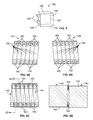
- FIG. 8A is a perspective view of a battery cell having terminal tabs.
- FIG. 8B is a perspective view of battery cells having terminal tabs oriented in tilted stacks with the terminal tabs facing one another.
- FIG. 8C is an illustrative plan view of two terminal tabs and two connectors prior to mating.
- FIG. 8D is an illustrative plan view of the two terminal tabs and two connectors from FIG. 8C showing the connectors mated.
- FIG. 9 is a perspective view of a portion of another traction battery assembly including a battery cell array having a plurality of battery cells.
- FIG. 10 is a perspective view of two of the battery cells of FIG. 9 showing foil terminals folded over to partially cover opposing faces of the respective cells.
- FIG. 11 is a plan view of the portion of the traction battery assembly of FIG. 9 .
- FIG. 12 is a perspective view of another two battery cells showing terminal tabs folded over to partially cover opposing faces of the respective cells.
- FIG. 1 depicts a schematic of an example of a plug-in hybrid-electric vehicle (PHEV).
- a vehicle 12 may comprise one or more electric machines 14 mechanically connected to a hybrid transmission 16 .
- the electric machines 14 may be capable of operating as a motor or a generator.
- the hybrid transmission 16 may be mechanically connected to an engine 18 .
- the hybrid transmission 16 may also be mechanically connected to a drive shaft 20 that is mechanically connected to the wheels 22 .
- the electric machines 14 may provide propulsion and deceleration capability when the engine 18 is turned on or off.
- the electric machines 14 may also act as generators and provide fuel economy benefits by recovering energy that would normally be lost as heat in the friction braking system.
- the electric machines 14 may also provide reduced pollutant emissions since the hybrid-electric vehicle 12 may be operated in electric mode or hybrid mode under certain conditions to reduce overall fuel consumption of the vehicle 12 .
- a traction battery or battery pack 24 stores and provides energy that may be used by the electric machines 14 .
- the traction battery 24 typically provides a high voltage DC output from one or more battery cell arrays, sometimes referred to as battery cell stacks, within the traction battery 24 .
- the battery cell arrays may include one or more battery cells.
- the traction battery 24 is electrically connected to one or more power electronics modules 26 through one or more contactors (not shown). The one or more contactors may isolate the fraction battery 24 from other components when opened and connect the traction battery 24 to other components when closed.
- the power electronics module 26 is also electrically connected to the electric machines 14 and provides the ability to bi-directionally transfer electrical energy between the traction battery 24 and the electric machines 14 .
- a typical traction battery 24 may provide a DC voltage while the electric machines 14 may require a three-phase AC voltage to function.
- the power electronics module 26 may convert the DC voltage to a three-phase AC voltage as required by the electric machines 14 .
- the power electronics module 26 may convert the three-phase AC voltage from the electric machines 14 acting as generators to the DC voltage required by the fraction battery 24 .
- the description herein is equally applicable to a pure electric vehicle.
- the hybrid transmission 16 may be a gear box connected to an electric machine 14 and the engine 18 may not be present.
- the traction battery 24 may provide energy for other vehicle electrical systems.
- a typical system may include a DC/DC converter module 28 that converts the high voltage DC output of the traction battery 24 to a low voltage DC supply that is compatible with other vehicle loads.
- Other high-voltage loads such as compressors and electric heaters, may be connected directly to the high-voltage without the use of a DC/DC converter module 28 .
- the low-voltage systems are electrically connected to an auxiliary battery 30 (e.g., 12V battery).
- a battery electronic control module (BECM) 33 may be in communication with the traction battery 24 .
- the BECM 33 may act as a controller for the traction battery 24 and may also include an electronic monitoring system that manages temperature and charge state of each of the battery cells.
- the traction battery 24 may have a temperature sensor 31 such as a thermistor or other temperature gauge.
- the temperature sensor 31 may be in communication with the BECM 33 to provide temperature data regarding the traction battery 24 .
- the temperature sensor 31 may also be located on or near the battery cells within the traction battery 24 . It is also contemplated that more than one temperature sensor 31 may be used to monitor temperature of the battery cells.
- the vehicle 12 may be, for example, an electric vehicle such as a PHEV, a FHEV, a MHEV, or a BEV in which the traction battery 24 may be recharged by an external power source 36 .
- the external power source 36 may be a connection to an electrical outlet.
- the external power source 36 may be electrically connected to electric vehicle supply equipment (EVSE) 38 .
- the EVSE 38 may provide circuitry and controls to regulate and manage the transfer of electrical energy between the power source 36 and the vehicle 12 .
- the external power source 36 may provide DC or AC electric power to the EVSE 38 .
- the EVSE 38 may have a charge connector 40 for plugging into a charge port 34 of the vehicle 12 .
- the charge port 34 may be any type of port configured to transfer power from the EVSE 38 to the vehicle 12 .
- the charge port 34 may be electrically connected to a charger or on-board power conversion module 32 .
- the power conversion module 32 may condition the power supplied from the EVSE 38 to provide the proper voltage and current levels to the fraction battery 24 .
- the power conversion module 32 may interface with the EVSE 38 to coordinate the delivery of power to the vehicle 12 .
- the EVSE connector 40 may have pins that mate with corresponding recesses of the charge port 34 .
- the various components discussed may have one or more associated controllers to control and monitor the operation of the components.
- the controllers may communicate via a serial bus (e.g., Controller Area Network (CAN)) or via discrete conductors.
- serial bus e.g., Controller Area Network (CAN)
- CAN Controller Area Network
- the battery cells may include electrochemical cells that convert stored chemical energy to electrical energy.
- Prismatic cells may include a housing, a positive electrode (cathode) and a negative electrode (anode).
- An electrolyte may allow ions to move between the anode and cathode during discharge, and then return during recharge.
- Terminals may allow current to flow out of the cell for use by the vehicle.
- the terminals of each battery cell When positioned in an array with multiple battery cells, the terminals of each battery cell may be aligned with opposing terminals (positive and negative) adjacent to one another and a busbar may assist in facilitating a series connection between the multiple battery cells.
- the battery cells may also be arranged in parallel such that similar terminals (positive and positive or negative and negative) are adjacent to one another. For example, two battery cells may be arranged with positive terminals adjacent to one another, and the next two cells may be arranged with negative terminals adjacent to one another. In this example, the busbar may contact terminals of all four cells.
- the fraction battery 24 may be heated and/or cooled using a liquid thermal management system, an air thermal management system, or other method as known in the art.
- the traction battery 24 may include a battery cell array 88 shown supported by a thermal plate 90 to be heated and/or cooled by a thermal management system.
- the battery cell array 88 may include a plurality of battery cells 92 positioned adjacent to one another and structural components.
- the DC/DC converter module 28 and/or the BECM 33 may also require cooling and/or heating under certain operating conditions.
- a thermal plate 91 may support the DC/DC converter module 28 and BECM 33 and assist in thermal management thereof.
- the DC/DC converter module 28 may generate heat during voltage conversion which may need to be dissipated.
- thermal plates 90 and 91 may be in fluid communication with one another to share a common fluid inlet port and common outlet port.
- the battery cell array 88 may be mounted to the thermal plate 90 such that only one surface, of each of the battery cells 92 , such as a bottom surface, is in contact with the thermal plate 90 .
- the thermal plate 90 and individual battery cells 92 may transfer heat between one another to assist in managing the thermal conditioning of the battery cells 92 within the battery cell array 88 during vehicle operations.
- Uniform thermal fluid distribution and high heat transfer capability are two thermal plate 90 considerations for providing effective thermal management of the battery cells 92 within the battery cell arrays 88 and other surrounding components. Since heat transfers between thermal plate 90 and thermal fluid via conduction and convection, the surface area in a thermal fluid flow field is important for effective heat transfer, both for removing heat and for heating the battery cells 92 at cold temperatures. For example, charging and discharging the battery cells generates heat which may negatively impact performance and life of the battery cell array 88 if not removed.
- the thermal plate 90 may also provide heat to the battery cell array 88 when subjected to cold temperatures.
- the thermal plate 90 may include one or more channels 93 and/or a cavity to distribute thermal fluid through the thermal plate 90 .
- the thermal plate 90 may include an inlet port 94 and an outlet port 96 that may be in communication with the channels 93 for providing and circulating the thermal fluid.
- Positioning of the inlet port 94 and outlet port 96 relative to the battery cell arrays 88 may vary.
- the inlet port 94 and outlet port 96 may be centrally positioned relative to the battery cell arrays 88 .
- the inlet port 94 and outlet port 96 may also be positioned to the side of the battery cell arrays 88 .
- the thermal plate 90 may define a cavity (not shown) in communication with the inlet port 94 and outlet port 96 for providing and circulating the thermal fluid.
- the thermal plate 91 may include an inlet port 95 and an outlet port 97 to deliver and remove thermal fluid.
- a sheet of thermal interface material (not shown) may be applied to the thermal plate 90 and/or 91 below the battery cell array 88 and/or the DC/DC converter module 28 and BECM 33 , respectively.
- the sheet of thermal interface material may enhance heat transfer between the battery cell array 88 and the thermal plate 90 by filling, for example, voids and/or air gaps between the battery cells 92 and the thermal plate 90 .
- the thermal interface material may also provide electrical insulation between the battery cell array 88 and the thermal plate 90 .
- a battery tray 98 may support the thermal plate 90 , the thermal plate 91 , the battery cell array 88 , and other components.
- the battery tray 98 may include one or more recesses to receive thermal plates.
- the battery cell array 88 may be contained within a cover or housing (not shown) to protect and enclose the battery cell array 88 and other surrounding components, such as the DC/DC converter module 28 and the BECM 33 .
- the battery cell array 88 may be positioned at several different locations including below a front seat, below a rear seat, or behind the rear seat of the vehicle, for example. However, it is contemplated the battery cell array 88 may be positioned at any suitable location in the vehicle 12 .
- HV batteries may consist of a plurality of battery cells connected to one another in series or in parallel.
- battery cells such as prismatic cells and pouch cells, connected in series
- the positive terminal of the first cell is electrically connected to the negative terminal of the next cell in the series.
- a busbar module is typically a separate component which assists in orienting and aligning terminals to facilitate the electrical connection between the cells and/or to assist in orienting busbars which span between the terminals.
- FIG. 3 shows an example of a HV battery 100 having a plurality of battery cells 102 which are electrically connected in series via busbars.
- a busbar module 108 assists in orienting the busbars and terminals 110 of the battery cells 102 . As shown in FIG.
- the terminals 110 extend from an upper face of the battery cells 102 and the battery cells 102 are oriented in a vertical formation. This location of the terminals 110 may require additional components to facilitate the series electrical connection between the battery cells 102 . Alternatively, direct cell-to-cell electrical connection between terminals of a battery cell array may provide packaging advantages and reduce a number of supporting components, such as busbar modules.
- FIGS. 4 through 7C show an example of a portion of a traction battery assembly 140 having a first battery cell array 142 , a second battery cell array 144 , and a frame 148 which may retain the battery cell arrays 142 and 144 therebetween.
- the first battery cell array 142 and the second battery cell array 144 may each have a plurality of battery cells 150 .
- the battery cells 150 may each define an upper face 152 , a lower face 154 , opposing front faces 156 , and opposing side faces 158 .
- the battery cells 150 may be prismatic cells.
- a pair of terminals 160 may extend from each of the battery cells 150 .
- Each of the terminals 160 may define a substantially flat contact surface.
- the terminals 160 may extend from upper and lower portions from one of the opposing side faces 158 of the battery cells 150 .
- One of the terminals 160 is a positive terminal and the other of the terminals 160 is a negative terminal.
- the battery cells 150 may be oriented in tilted stacks such that the terminals 160 of at least one of the battery cells 150 of one of the battery cells arrays 142 and 144 are aligned with oppositely charged terminals 160 of two different battery cells 150 of the other array.
- the first battery cell array 142 may have the positive terminals located at the upper portions of one of the opposing side faces 158 and the negative terminals located at the lower portions of one of the opposing side faces 158 .
- the second battery cell array 144 may have the positive terminals located at the lower portions of one of the opposing side faces 158 and the negative terminals located at the upper portion of one of the opposing side faces 158 . Further, the terminals 160 from the battery cell array 142 and the battery cell array 144 may be facing one another.
- the frame 148 may support and orient the battery cells 150 of the battery cell arrays 142 and 144 .
- the battery cells 150 may be oriented in tilted stacks such that the battery cells 150 are tilted at a tilt angle relative to the frame 148 or a component beneath the battery cells 150 such as a battery tray (not shown) or thermal plate (not shown).
- the battery cells 150 of the first battery cell array 142 may be tilted in a direction opposite the tilt of the battery cells 150 of the second battery cell array 144 .
- the positive and negative terminals of the terminals 160 may be aligned, in registration, and/or in contact with the oppositely charged terminals 160 of two different battery cells 150 of the other array, thus eliminating inclusion of a busbar module within the traction battery assembly 140 .
- the battery cells 150 may be oriented such that the battery cells 150 of the first battery cell array 142 are tilted at a first angle relative to a vertical axis 159 and the battery cells of the second array at a second angle of the same magnitude of the first angle but in an opposite direction relative to the vertical axis 159 .
- a degree of the first and second angles may be based on a width and length of one of the side faces 158 of the battery cells 150 to facilitate the alignment of the terminals 160 for the battery cells 150 in the tilted stack.
- FIG. 7B is a plan view of one of the battery cells 150 having a width (“W”), and a length (“L”) defined by a distance between center points of the terminals 160 .
- An angle between two of the battery cells 150 oriented in the tilted stack with aligned terminals 160 is represented by ⁇ as shown in FIG. 7B .
- Planes defined by terminal axis centerlines 164 may define the angle ⁇ .
- Planes defined by two of the front faces 156 of different battery cells 150 may define the angle ⁇ .
- the vertical axis 159 may extend substantially perpendicularly from a surface supporting the battery cells 150 . It is contemplated that under certain conditions, one or more components may be located between adjacent battery cells 150 .
- the one or more components may be, for example, a cell spacer, fin, or thermal plate.
- the width W may be defined by the width of the battery cell 150 and the width of the one or more components. Plates (not shown) having conductive and impedance characteristics may be fused between opposing terminals 160 to assist in facilitating the electrical connection between the battery cells 150 .
- the frame 148 may include endplates 165 and side components 166 which may be configured to apply one or more clamping loads to compress the battery cell arrays 142 and 144 against one another.
- the positive and negative terminals of the terminals 160 may contact the respective oppositely charged terminals when compressed to facilitate an electrical series connection across the battery cell arrays 142 and 144 .
- Arrows included in FIG. 7A illustrate an example of directions of the compression forces which may be applied to the battery cell arrays 142 and 144 .
- each of the battery cell arrays 142 and 144 may have a battery cell 150 at opposite longitudinal ends of the arrays with a terminal which is not in electrical communication with another battery cell 150 , such as a terminal 150 a of the battery cells 150 of the battery cell array 142 and a terminal 150 b of the battery cells 150 of the battery cell array 144 .
- Terminals 150 a and 150 b may be in electrical connection with other components, such as a wire harness or electrical output conductor.
- FIGS. 8A through 8D show examples of alternative terminal configurations which may be utilized with the battery cells 150 when oriented in tilted stacks.
- the battery cell 150 may include a positive terminal tab 260 a and a negative terminal tab 260 b which may be referred to as terminal tabs 260 a and 260 b .
- the terminal tabs 260 a and 260 b may at least partially extend through respective planes 262 a and 262 b , which may be defined by the upper face 152 and the lower face 154 of the battery cell 150 .
- the terminal tabs 260 a and 260 b may be oriented and aligned to contact oppositely charged terminal tabs of two other battery cells 150 .
- the positive terminal tab 260 a and the negative terminal tab 260 b may be joined to one another to facilitate and electrical connection therebetween. Examples of joining methods include ultrasonic welding and resistance welding.
- One or more connectors may be configured to receive and align the terminals 160 such that oppositely charged terminals 160 may be electrically connected when the connectors mate.
- FIGS. 8C and 8D show a male connector 280 and a female connector 282 which may each house a positive or negative terminal 160 .
- the male connector 280 and the female connector 282 may be configured to mate with one another such that the oppositely charged terminals 160 contact one another to facilitate an electrical connection therebetween.
- a single connector (not shown) may be configured to receive oppositely charged terminals 160 such that the oppositely charged terminals 160 contact one another to facilitate an electrical connection therebetween.
- FIGS. 9 through 12 show an example of a portion of a traction battery assembly 300 which may include a battery cell array 304 having a plurality of battery cells 310 .
- a frame 306 may support and retain the battery cells 310 .
- the battery cells 310 may each have opposing front faces 312 .
- a pair of terminals may extend from an upper portion or upper end of each battery cell 310 .
- the battery cells 310 may be pouch cells.
- a pouch cell may include conductive positive and negative foil terminals which resemble tabs extending from a body of the pouch cell. The foil terminals may be welded to an electrode within the pouch cell.
- Pouch cells may use a foil bag or pouch to retain the components of the cell therein instead of a substantially rigid case as is commonly used with prismatic cells.
- the terminals of the battery cells 310 may be folded over onto alternate opposing front faces 312 .
- a positive foil terminal 316 a may partially cover one of the opposing faces 312 and a negative foil terminal 316 b may partially cover the other of the opposing faces 312 .
- An electrical insulator component (not shown) may be secured to the battery cells 310 at locations under which the respective positive foil terminal 316 a and the negative foil terminal 316 b partially cover.
- the battery cells 310 may be stacked such that the positive foil terminals 316 a are aligned with negative foil terminals 316 b of adjacent cells.
- the battery cells 310 at the outer ends of the battery cell array 304 may have an electrical connection with other components of the traction battery assembly 300 , such as a wire harness and an electrical output conductor.
- the frame 306 may include components, such as endplates 320 and side components 322 .
- the endplates 320 may be configured to apply opposing longitudinal compression forces, or clamping loads, to the battery cells 310 .
- the side components 322 may be configured to apply opposing lateral compression forces, or clamping loads, to the battery cells 310 .
- the longitudinal compression forces and the lateral compression forces may be such that the positive foil terminals 316 a and the negative foil terminals 316 b contact one another to assist in facilitating a series electrical connection across the battery cell array 304 .
- Arrows included in FIG. 11 illustrate an example of directions of the compression forces which may be applied to the battery cell array 304 .
- a busbar module may not be required since the positive foil terminals 316 a and the negative foil terminals 316 b do not extend above the battery cell array 304 and are instead contacting one another.
- the battery cells 310 may be spaced apart such that a component, such as a cell spacer (not shown) may be disposed between the cells.
- the cell spacer may be sized such that the positive foil terminals 316 a and the negative foil terminals 316 b of adjacent battery cells 310 may still contact one another. Plates (not shown) having conductive and impedance characteristics may be fused between the positive foil terminals 316 a and the negative foil terminals 316 b to assist in facilitating the electrical connection between the battery cells 310 .
- FIG. 12 shows an example of two prismatic battery cells 400 which may each include a positive terminal tab 410 a and a negative terminal tab 410 b on an upper portion or upper end of the battery cells 400 .
- the terminal tabs 410 a and 410 b may be folded over onto alternate opposing front faces 412 .
- the positive terminal tab 410 a may partially cover one of the opposing faces 412
- the negative terminal tab 410 b may partially cover the other of the opposing faces 412 .
- An electrical insulator component (not shown) may be secured to the battery cells 400 at locations under which the respective terminal tabs 410 a and 410 b partially cover.
- the battery cells 400 may be stacked such that the positive terminal tabs 410 a are aligned with the negative terminal tabs 410 b of adjacent cells.
- a plurality of battery cells 400 may be stacked in a fashion similar to that of the battery cell array 304 .
Landscapes
- Chemical & Material Sciences (AREA)
- Chemical Kinetics & Catalysis (AREA)
- Electrochemistry (AREA)
- General Chemical & Material Sciences (AREA)
- Engineering & Computer Science (AREA)
- Manufacturing & Machinery (AREA)
- Sustainable Energy (AREA)
- Sustainable Development (AREA)
- Life Sciences & Earth Sciences (AREA)
- Power Engineering (AREA)
- Transportation (AREA)
- Mechanical Engineering (AREA)
- Aviation & Aerospace Engineering (AREA)
- Battery Mounting, Suspending (AREA)
- Secondary Cells (AREA)
- Connection Of Batteries Or Terminals (AREA)
Priority Applications (3)
| Application Number | Priority Date | Filing Date | Title |
|---|---|---|---|
| US14/464,191 US9478779B2 (en) | 2014-08-20 | 2014-08-20 | Cell to cell terminal connections for a high voltage battery |
| DE102015113564.7A DE102015113564A1 (de) | 2014-08-20 | 2015-08-17 | Anschlussverbindungen von zelle zu zelle für eine hochspannungsbatterie |
| CN201510514747.3A CN105390658B (zh) | 2014-08-20 | 2015-08-20 | 高压电池的电池单元端子连接 |
Applications Claiming Priority (1)
| Application Number | Priority Date | Filing Date | Title |
|---|---|---|---|
| US14/464,191 US9478779B2 (en) | 2014-08-20 | 2014-08-20 | Cell to cell terminal connections for a high voltage battery |
Publications (2)
| Publication Number | Publication Date |
|---|---|
| US20160056430A1 US20160056430A1 (en) | 2016-02-25 |
| US9478779B2 true US9478779B2 (en) | 2016-10-25 |
Family
ID=55274039
Family Applications (1)
| Application Number | Title | Priority Date | Filing Date |
|---|---|---|---|
| US14/464,191 Active 2035-01-18 US9478779B2 (en) | 2014-08-20 | 2014-08-20 | Cell to cell terminal connections for a high voltage battery |
Country Status (3)
| Country | Link |
|---|---|
| US (1) | US9478779B2 (de) |
| CN (1) | CN105390658B (de) |
| DE (1) | DE102015113564A1 (de) |
Cited By (3)
| Publication number | Priority date | Publication date | Assignee | Title |
|---|---|---|---|---|
| US20180069336A1 (en) * | 2016-09-08 | 2018-03-08 | Lisa Draexlmaier Gmbh | Plug Connector to Connect Two Electrical Assemblies |
| US10632856B2 (en) | 2017-01-19 | 2020-04-28 | Ford Global Technologies, Llc | Connector-integrated endplate for battery electric vehicles |
| US10850725B2 (en) | 2017-12-08 | 2020-12-01 | Ford Global Technologies, Llc | Vehicles with modular parallel high voltage batteries |
Families Citing this family (12)
| Publication number | Priority date | Publication date | Assignee | Title |
|---|---|---|---|---|
| US10062931B2 (en) | 2015-04-22 | 2018-08-28 | Johnson Controls Technology Company | Welding process for battery module components |
| KR102408824B1 (ko) | 2015-06-22 | 2022-06-13 | 삼성에스디아이 주식회사 | 이차 전지 및 이차 전지 모듈 |
| WO2017176964A1 (en) * | 2016-04-08 | 2017-10-12 | 19Labs Inc. | Systems and methods for supplying power to removable storage compartments |
| KR102654925B1 (ko) | 2016-06-21 | 2024-04-05 | 삼성디스플레이 주식회사 | 디스플레이 장치 및 이의 제조 방법 |
| JP6571621B2 (ja) | 2016-10-05 | 2019-09-04 | 矢崎総業株式会社 | 電池モジュール |
| CN107808939A (zh) * | 2017-09-26 | 2018-03-16 | 努比亚技术有限公司 | 一种终端电池结构和移动终端 |
| DE102018202120A1 (de) | 2018-02-12 | 2019-08-14 | Airbus Defence and Space GmbH | Batterieanordnung zur strukturellen Integration von Batterien in ein Fahrzeug |
| DE102018204420A1 (de) * | 2018-03-22 | 2019-09-26 | Airbus Defence and Space GmbH | Batterieanordnung zur lasttragenden strukturellen Integration von Batterien in ein Fahrzeug |
| CN111384335B (zh) * | 2018-12-30 | 2024-09-13 | 宁德时代新能源科技股份有限公司 | 一种电池包及车辆 |
| DE102019216606A1 (de) * | 2019-10-29 | 2021-04-29 | Thyssenkrupp Ag | Batteriemodul |
| JPWO2023170852A1 (de) * | 2022-03-10 | 2023-09-14 | ||
| DE102022207281A1 (de) | 2022-07-18 | 2024-01-18 | Volkswagen Aktiengesellschaft | Batteriesystem und Verfahren zur Herstellung eines Batteriesystems |
Citations (13)
| Publication number | Priority date | Publication date | Assignee | Title |
|---|---|---|---|---|
| US6495282B1 (en) * | 1999-07-22 | 2002-12-17 | Japan Storage Battery Co., Ltd. | Method for arranging elliptic cylindrical cell and assembled battery |
| US20030017387A1 (en) * | 2001-07-23 | 2003-01-23 | Shuhei Marukawa | Battery pack |
| US20030091896A1 (en) * | 2001-11-14 | 2003-05-15 | Nissan Motor Co., Ltd. | Assembled battery |
| US20050142439A1 (en) * | 2003-12-26 | 2005-06-30 | Sang-Ho Lee | Pouch type lithium secondary battery |
| US20070054561A1 (en) | 2005-09-02 | 2007-03-08 | Gutman Robert F | Integrated Module Connection For HEV Battery |
| US7508165B2 (en) | 2004-10-19 | 2009-03-24 | Denso Corporation | Cell voltage equalization apparatus for combined battery pack including circuit driven by power supplied by the combined battery pack |
| US20110293994A1 (en) * | 2010-05-27 | 2011-12-01 | Gm Global Technology Operations Llc. | Battery pack assembly using clad electrical connections |
| US8235732B2 (en) | 2008-05-15 | 2012-08-07 | Johnson Controls—SAFT Advanced Power Solutions LLC | Battery system |
| US20120244403A1 (en) | 2010-12-07 | 2012-09-27 | Maskew Brian J | Battery array safety covers for energy storage system |
| US20130189560A1 (en) | 2012-01-19 | 2013-07-25 | Ford Global Technologies, Llc | Materials And Methods For Joining Battery Cell Terminals And Interconnector Busbars |
| US20130273412A1 (en) | 2010-10-30 | 2013-10-17 | Wataru Okada | Battery pack and vehicle including the same |
| US20130273411A1 (en) * | 2012-04-12 | 2013-10-17 | Robert Bosch Gmbh | Rechargeable battery and module thereof |
| US20140042957A1 (en) | 2012-08-08 | 2014-02-13 | Nxp B.V. | Energy storage cell for a multi-cell energy storage device |
Family Cites Families (3)
| Publication number | Priority date | Publication date | Assignee | Title |
|---|---|---|---|---|
| JPH11149935A (ja) * | 1997-11-18 | 1999-06-02 | Japan Storage Battery Co Ltd | 蓄電池 |
| KR100627394B1 (ko) * | 2004-11-30 | 2006-09-21 | 삼성에스디아이 주식회사 | 이차 전지 모듈 |
| JP5862077B2 (ja) * | 2011-07-05 | 2016-02-16 | 株式会社オートネットワーク技術研究所 | 電池配線モジュール |
-
2014
- 2014-08-20 US US14/464,191 patent/US9478779B2/en active Active
-
2015
- 2015-08-17 DE DE102015113564.7A patent/DE102015113564A1/de not_active Withdrawn
- 2015-08-20 CN CN201510514747.3A patent/CN105390658B/zh not_active Expired - Fee Related
Patent Citations (13)
| Publication number | Priority date | Publication date | Assignee | Title |
|---|---|---|---|---|
| US6495282B1 (en) * | 1999-07-22 | 2002-12-17 | Japan Storage Battery Co., Ltd. | Method for arranging elliptic cylindrical cell and assembled battery |
| US20030017387A1 (en) * | 2001-07-23 | 2003-01-23 | Shuhei Marukawa | Battery pack |
| US20030091896A1 (en) * | 2001-11-14 | 2003-05-15 | Nissan Motor Co., Ltd. | Assembled battery |
| US20050142439A1 (en) * | 2003-12-26 | 2005-06-30 | Sang-Ho Lee | Pouch type lithium secondary battery |
| US7508165B2 (en) | 2004-10-19 | 2009-03-24 | Denso Corporation | Cell voltage equalization apparatus for combined battery pack including circuit driven by power supplied by the combined battery pack |
| US20070054561A1 (en) | 2005-09-02 | 2007-03-08 | Gutman Robert F | Integrated Module Connection For HEV Battery |
| US8235732B2 (en) | 2008-05-15 | 2012-08-07 | Johnson Controls—SAFT Advanced Power Solutions LLC | Battery system |
| US20110293994A1 (en) * | 2010-05-27 | 2011-12-01 | Gm Global Technology Operations Llc. | Battery pack assembly using clad electrical connections |
| US20130273412A1 (en) | 2010-10-30 | 2013-10-17 | Wataru Okada | Battery pack and vehicle including the same |
| US20120244403A1 (en) | 2010-12-07 | 2012-09-27 | Maskew Brian J | Battery array safety covers for energy storage system |
| US20130189560A1 (en) | 2012-01-19 | 2013-07-25 | Ford Global Technologies, Llc | Materials And Methods For Joining Battery Cell Terminals And Interconnector Busbars |
| US20130273411A1 (en) * | 2012-04-12 | 2013-10-17 | Robert Bosch Gmbh | Rechargeable battery and module thereof |
| US20140042957A1 (en) | 2012-08-08 | 2014-02-13 | Nxp B.V. | Energy storage cell for a multi-cell energy storage device |
Cited By (4)
| Publication number | Priority date | Publication date | Assignee | Title |
|---|---|---|---|---|
| US20180069336A1 (en) * | 2016-09-08 | 2018-03-08 | Lisa Draexlmaier Gmbh | Plug Connector to Connect Two Electrical Assemblies |
| US10044126B2 (en) * | 2016-09-08 | 2018-08-07 | Lisa Draexlmaier Gmbh | Plug connector to connect two electrical assemblies |
| US10632856B2 (en) | 2017-01-19 | 2020-04-28 | Ford Global Technologies, Llc | Connector-integrated endplate for battery electric vehicles |
| US10850725B2 (en) | 2017-12-08 | 2020-12-01 | Ford Global Technologies, Llc | Vehicles with modular parallel high voltage batteries |
Also Published As
| Publication number | Publication date |
|---|---|
| DE102015113564A1 (de) | 2016-02-25 |
| CN105390658A (zh) | 2016-03-09 |
| US20160056430A1 (en) | 2016-02-25 |
| CN105390658B (zh) | 2019-07-26 |
Similar Documents
| Publication | Publication Date | Title |
|---|---|---|
| US9478779B2 (en) | Cell to cell terminal connections for a high voltage battery | |
| US11462805B2 (en) | Busbar assembly for vehicle traction battery | |
| US9296310B2 (en) | Traction battery thermal management system | |
| US10186737B2 (en) | Traction battery integrated thermal plate and tray | |
| US9755212B2 (en) | Traction battery busbar carriers for pouch battery cells | |
| US10141550B2 (en) | Pouch battery cell assembly for traction battery | |
| US9634364B2 (en) | Support structure for traction battery assembly with integrated thermal plate | |
| CN105470421B (zh) | 牵引电池组件 | |
| US10090494B2 (en) | Support structure for battery cells within a traction battery assembly | |
| US10749225B2 (en) | Thermal management assembly for traction battery cells | |
| US10632856B2 (en) | Connector-integrated endplate for battery electric vehicles | |
| US9484562B2 (en) | Traction battery assembly | |
| US10109829B2 (en) | Support assembly for traction battery | |
| US20150263397A1 (en) | Side mounted traction battery thermal plate | |
| US9318751B2 (en) | Traction battery assembly with spring component | |
| US9929388B2 (en) | Traction battery assembly | |
| US20160064708A1 (en) | Angled Battery Cell Configuration for a Traction Battery Assembly | |
| CN105489963B (zh) | 车辆牵引电池组件 | |
| US9356270B2 (en) | Multi-tier traction battery assembly with alignment feature | |
| US9666844B2 (en) | Support structure for angled battery cell configuration for a traction battery assembly | |
| US9553288B2 (en) | Step configuration for traction battery housing | |
| US20240072378A1 (en) | Traction battery assembly having multipiece busbar module |
Legal Events
| Date | Code | Title | Description |
|---|---|---|---|
| AS | Assignment |
Owner name: FORD GLOBAL TECHNOLOGIES, LLC, MICHIGAN Free format text: ASSIGNMENT OF ASSIGNORS INTEREST;ASSIGNOR:BURKMAN, WESLEY EDWARD;REEL/FRAME:033574/0531 Effective date: 20140818 |
|
| STCF | Information on status: patent grant |
Free format text: PATENTED CASE |
|
| MAFP | Maintenance fee payment |
Free format text: PAYMENT OF MAINTENANCE FEE, 4TH YEAR, LARGE ENTITY (ORIGINAL EVENT CODE: M1551); ENTITY STATUS OF PATENT OWNER: LARGE ENTITY Year of fee payment: 4 |
|
| FEPP | Fee payment procedure |
Free format text: MAINTENANCE FEE REMINDER MAILED (ORIGINAL EVENT CODE: REM.); ENTITY STATUS OF PATENT OWNER: LARGE ENTITY |