US9475302B2 - Ink jet printing apparatus and ink jet printing method - Google Patents
Ink jet printing apparatus and ink jet printing method Download PDFInfo
- Publication number
- US9475302B2 US9475302B2 US14/489,745 US201414489745A US9475302B2 US 9475302 B2 US9475302 B2 US 9475302B2 US 201414489745 A US201414489745 A US 201414489745A US 9475302 B2 US9475302 B2 US 9475302B2
- Authority
- US
- United States
- Prior art keywords
- ink
- print head
- negative pressure
- pressure
- liquid chamber
- Prior art date
- Legal status (The legal status is an assumption and is not a legal conclusion. Google has not performed a legal analysis and makes no representation as to the accuracy of the status listed.)
- Expired - Fee Related
Links
- 238000007641 inkjet printing Methods 0.000 title claims abstract description 30
- 238000000034 method Methods 0.000 title claims description 44
- 239000007788 liquid Substances 0.000 claims abstract description 91
- 238000004891 communication Methods 0.000 claims abstract description 60
- 238000007639 printing Methods 0.000 claims description 51
- 230000015572 biosynthetic process Effects 0.000 claims description 8
- 238000004140 cleaning Methods 0.000 claims description 4
- 238000001514 detection method Methods 0.000 claims description 3
- 230000001105 regulatory effect Effects 0.000 claims 1
- 239000000976 ink Substances 0.000 description 311
- 230000008569 process Effects 0.000 description 37
- 238000011084 recovery Methods 0.000 description 20
- 238000010586 diagram Methods 0.000 description 14
- 239000012528 membrane Substances 0.000 description 14
- 230000007423 decrease Effects 0.000 description 9
- 230000007246 mechanism Effects 0.000 description 9
- 230000005499 meniscus Effects 0.000 description 9
- 238000003825 pressing Methods 0.000 description 8
- 230000002463 transducing effect Effects 0.000 description 7
- 230000001965 increasing effect Effects 0.000 description 4
- 238000012545 processing Methods 0.000 description 4
- 239000002184 metal Substances 0.000 description 3
- 230000005587 bubbling Effects 0.000 description 2
- 230000003247 decreasing effect Effects 0.000 description 2
- 230000003028 elevating effect Effects 0.000 description 2
- 239000000835 fiber Substances 0.000 description 2
- 230000009467 reduction Effects 0.000 description 2
- 230000002040 relaxant effect Effects 0.000 description 2
- 239000002699 waste material Substances 0.000 description 2
- 238000009825 accumulation Methods 0.000 description 1
- 230000002411 adverse Effects 0.000 description 1
- 230000008901 benefit Effects 0.000 description 1
- 230000000903 blocking effect Effects 0.000 description 1
- 239000003086 colorant Substances 0.000 description 1
- 239000000428 dust Substances 0.000 description 1
- 230000000694 effects Effects 0.000 description 1
- 230000006870 function Effects 0.000 description 1
- 238000012986 modification Methods 0.000 description 1
- 230000004048 modification Effects 0.000 description 1
- 102220171488 rs760746448 Human genes 0.000 description 1
Images


Classifications
-
- B—PERFORMING OPERATIONS; TRANSPORTING
- B41—PRINTING; LINING MACHINES; TYPEWRITERS; STAMPS
- B41J—TYPEWRITERS; SELECTIVE PRINTING MECHANISMS, i.e. MECHANISMS PRINTING OTHERWISE THAN FROM A FORME; CORRECTION OF TYPOGRAPHICAL ERRORS
- B41J2/00—Typewriters or selective printing mechanisms characterised by the printing or marking process for which they are designed
- B41J2/005—Typewriters or selective printing mechanisms characterised by the printing or marking process for which they are designed characterised by bringing liquid or particles selectively into contact with a printing material
- B41J2/01—Ink jet
- B41J2/17—Ink jet characterised by ink handling
- B41J2/175—Ink supply systems ; Circuit parts therefor
- B41J2/17566—Ink level or ink residue control
-
- B—PERFORMING OPERATIONS; TRANSPORTING
- B41—PRINTING; LINING MACHINES; TYPEWRITERS; STAMPS
- B41J—TYPEWRITERS; SELECTIVE PRINTING MECHANISMS, i.e. MECHANISMS PRINTING OTHERWISE THAN FROM A FORME; CORRECTION OF TYPOGRAPHICAL ERRORS
- B41J2/00—Typewriters or selective printing mechanisms characterised by the printing or marking process for which they are designed
- B41J2/005—Typewriters or selective printing mechanisms characterised by the printing or marking process for which they are designed characterised by bringing liquid or particles selectively into contact with a printing material
- B41J2/01—Ink jet
- B41J2/135—Nozzles
- B41J2/14—Structure thereof only for on-demand ink jet heads
-
- B—PERFORMING OPERATIONS; TRANSPORTING
- B41—PRINTING; LINING MACHINES; TYPEWRITERS; STAMPS
- B41J—TYPEWRITERS; SELECTIVE PRINTING MECHANISMS, i.e. MECHANISMS PRINTING OTHERWISE THAN FROM A FORME; CORRECTION OF TYPOGRAPHICAL ERRORS
- B41J2/00—Typewriters or selective printing mechanisms characterised by the printing or marking process for which they are designed
- B41J2/005—Typewriters or selective printing mechanisms characterised by the printing or marking process for which they are designed characterised by bringing liquid or particles selectively into contact with a printing material
- B41J2/01—Ink jet
- B41J2/17—Ink jet characterised by ink handling
- B41J2/175—Ink supply systems ; Circuit parts therefor
- B41J2/17503—Ink cartridges
- B41J2/1752—Mounting within the printer
-
- B—PERFORMING OPERATIONS; TRANSPORTING
- B41—PRINTING; LINING MACHINES; TYPEWRITERS; STAMPS
- B41J—TYPEWRITERS; SELECTIVE PRINTING MECHANISMS, i.e. MECHANISMS PRINTING OTHERWISE THAN FROM A FORME; CORRECTION OF TYPOGRAPHICAL ERRORS
- B41J2/00—Typewriters or selective printing mechanisms characterised by the printing or marking process for which they are designed
- B41J2/005—Typewriters or selective printing mechanisms characterised by the printing or marking process for which they are designed characterised by bringing liquid or particles selectively into contact with a printing material
- B41J2/01—Ink jet
- B41J2/17—Ink jet characterised by ink handling
- B41J2/175—Ink supply systems ; Circuit parts therefor
- B41J2/17503—Ink cartridges
- B41J2/17556—Means for regulating the pressure in the cartridge
-
- B—PERFORMING OPERATIONS; TRANSPORTING
- B41—PRINTING; LINING MACHINES; TYPEWRITERS; STAMPS
- B41J—TYPEWRITERS; SELECTIVE PRINTING MECHANISMS, i.e. MECHANISMS PRINTING OTHERWISE THAN FROM A FORME; CORRECTION OF TYPOGRAPHICAL ERRORS
- B41J29/00—Details of, or accessories for, typewriters or selective printing mechanisms not otherwise provided for
- B41J29/38—Drives, motors, controls or automatic cut-off devices for the entire printing mechanism
-
- B—PERFORMING OPERATIONS; TRANSPORTING
- B41—PRINTING; LINING MACHINES; TYPEWRITERS; STAMPS
- B41J—TYPEWRITERS; SELECTIVE PRINTING MECHANISMS, i.e. MECHANISMS PRINTING OTHERWISE THAN FROM A FORME; CORRECTION OF TYPOGRAPHICAL ERRORS
- B41J2/00—Typewriters or selective printing mechanisms characterised by the printing or marking process for which they are designed
- B41J2/005—Typewriters or selective printing mechanisms characterised by the printing or marking process for which they are designed characterised by bringing liquid or particles selectively into contact with a printing material
- B41J2/01—Ink jet
- B41J2/17—Ink jet characterised by ink handling
- B41J2/175—Ink supply systems ; Circuit parts therefor
- B41J2/17566—Ink level or ink residue control
- B41J2002/17579—Measuring electrical impedance for ink level indication
Definitions
- the present invention relates to an ink jet printing apparatus and an ink jet printing method in which an image is printed using an ink tank that contains ink in a closed space so as to apply a negative pressure to the ink and a print head that can eject the ink fed from the ink tank.
- ink with a negative pressure applied thereto is fed from an ink tank to a print head and then ejected through ejection ports in the print head using an ejection energy generating element such as an electrothermal transducing element (heater) or a piezo element.
- an ejection energy generating element such as an electrothermal transducing element (heater) or a piezo element.
- a closed ink tank is advantageously used.
- a flexible bag containing ink is provided and biased, using a spring or the like, in a direction in which the internal volume of the bag is increased, to apply a negative pressure to the ink to be fed to the print head.
- the flexible bag containing ink forms a closed space that communicates only with the print head.
- the negative pressure in the print head increases when the print head ejects the ink remaining inside the print head. This may preclude the ink from being appropriately ejected, leading to inappropriate image printing.
- the present invention provides an ink jet printing apparatus and an ink jet printing method both of which allow ink in a closed ink tank and in a print head to be stably ejected.
- an ink jet printing apparatus comprising:
- a print head configured to be able to eject an ink fed from an ink tank that contains the ink in a closed space so as to apply a negative pressure to the ink
- a communication path configured to allow a liquid chamber in the print head to communicate with an outside of the liquid chamber
- an opening and closing unit configured to open and close the communication path
- control unit configured to open the communication path in accordance with a pressure in the print head via the opening and closing unit, to bring the liquid chamber and the outside into communication with each other.
- an ink jet printing method for printing an image by ejecting, from a print head, ink fed from an inside of a closed space in an ink tank to which a negative pressure is applied, the method comprising:
- the opening and closing unit opens the communication path in accordance with the pressure in the print head to bring the outside and the print head into communication with each other, thus relaxing the negative pressure in the print head. This enables the ink in the closed ink tank and in the print head to be stably ejected.
- FIG. 1 is a schematic front view of an ink jet printing apparatus according to a first embodiment of the present invention
- FIG. 2 is a block diagram of a control system in the ink jet printing apparatus in FIG. 1 ;
- FIG. 3 is a schematic diagram of a configuration of an ink supply system in the ink jet printing apparatus in FIG. 1 ;
- FIG. 4 is an enlarged cross-sectional view of an ink tank and a print head in FIG. 3 ;
- FIG. 6 is a flowchart illustrating a negative pressure relaxation process executed by the ink supply system in FIG. 3 ;
- FIG. 7A , FIG. 7B , FIG. 7C , FIG. 7D , and FIG. 7E are diagrams illustrating an operation of the ink supply system during the negative pressure relaxation process in FIG. 6 ;
- FIG. 8 is a schematic diagram of a configuration of an important part of a second embodiment of the present invention.
- FIG. 9 is a flowchart illustrating a negative pressure relaxation process according to a third embodiment of the present invention.
- FIG. 10A , FIG. 10B , FIG. 10C , FIG. 10D , and FIG. 10E are diagrams illustrating an operation of the ink supply system during the negative pressure relaxation process in FIG. 9 ;
- FIG. 11 is a flowchart illustrating a negative pressure relaxation process executed by the ink supply system in FIG. 3 according to a fifth embodiment of the present invention.
- FIG. 12A , FIG. 12B , FIG. 12C , and FIG. 12D are diagrams illustrating an operation of the ink supply system during the negative pressure relaxation process in FIG. 11 ;
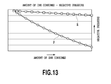
- FIG. 13 is a diagram illustrating a relation between the amount of ink consumed and the negative pressure in the print head.
- a printing apparatus is an applied example of a full line ink jet printing apparatus.
- FIG. 1 is a diagram of a conceptual example of a configuration of a full line ink jet printing apparatus (hereinafter also referred to as a “printer”) 110 .
- the printer 110 is connected to a host apparatus 120 configured as a personal computer or the like to transmit image information to the printer 110 .
- the printer 110 includes four print heads 22 ( 22 K, 22 C, 22 M, and 22 Y) capable of ejecting ink and which are arranged in juxtaposition in a direction in which rolled paper P serving as a print medium is conveyed (the direction of arrow A).
- the print heads 22 K, 22 C, 22 M, and 22 Y are print heads configured to eject black, cyan, magenta, and yellow, respectively.
- Each of the print heads 22 includes a plurality of nozzles with a plurality of ejection ports through which the corresponding ink is ejected using an ejection energy generating element such as an electrothermal transducing element (heater) or a piezo element.
- an ejection energy generating element such as an electrothermal transducing element (heater) or a piezo element.
- the electrothermal transducing element When the electrothermal transducing element is used, the electrothermal transducing element generates heat to bubble the ink so that the bubbling energy of the ink can be utilized to eject the ink through the ejection port at a leading end of the nozzle.
- the ejection ports are arranged in a direction crossing (in the present example, a direction orthogonal to) the conveying direction of arrow A.
- the print heads 22 are what is called elongate line heads, and the print heads 22 K, 22 C, 22 M, and 22 Y are arranged in juxtaposition in the conveying direction of arrow A.
- the length of each of the print heads 22 is slightly larger than the maximum width (the length in a direction orthogonal to the sheet of FIG. 1 ) of the print medium over which the printer 110 can achieve printing.
- the print heads 22 are placed at predetermined positions during an image printing operation.
- the printer 110 incorporates a recovery unit 400 .
- the recovery unit 400 includes recovery mechanisms (capping mechanisms) 50 configured to remove ink from corresponding surface of the print heads 22 K, 22 C, 22 M, and 22 Y on which the ejection ports are formed (ejection port formation surface).
- the recovery mechanisms 50 are provided independently in each of the print heads 22 K, 22 C, 22 M, and 22 Y.
- Each of the recovery mechanisms 50 includes a wiper that wipes the ejection port formation surface, a wiper holding member that holds the wiper, an ink removing member configured to remove ink attached to the wiper, and a cap that closely contacts the ejection port surface.
- the rolled paper P is fed from a supply unit 25 and conveyed in the direction of arrow A by a conveying mechanism 26 incorporated in the printer 110 .
- the conveying mechanism 26 includes a conveying belt 26 a on which the rolled paper P is placed and conveyed, a conveying motor 26 b configured to rotate the conveying belt 26 a , and a roller 26 c that applies tension to the conveying belt 26 a .
- the conveying mechanism 26 may be configured to convey the rolled paper P using the conveying roller or may provide a conveying unit.
- the printer 110 includes ink tanks 28 ( 28 K, 28 C, 28 M, and 28 Y) from which the respective inks are fed to the print heads 22 ( 22 K, 22 C, 22 M, and 22 Y). Moreover, the printer 110 includes various pumps configured to perform an ink supply operation and the recovery operation on each of the print heads 22 K, 22 C, 22 M, and 22 Y.
- FIG. 2 is a block diagram of a configuration of a control system of the printer 110 .
- the CPU 100 is an arithmetic processing apparatus that is responsible for general control in the printer 110 in connection with reception of print data for the printer 110 , a printing operation, and handling of the rolled paper P.
- the CPU 100 analyzes a received command and then decompresses image data on color components in print data into a bit map in an image memory 106 for drawing
- a roll motor (not shown in the drawings) configured to pay the rolled paper P out, a conveying motor 26 b configured to convey the rolled paper P at a constant speed, and the like are controllably driven via the output port 114 and the motor driving section 116 to convey the rolled paper P in the direction of arrow A.
- a timing (print timing) when ink starts to be ejected to the rolled paper P conveyed at the constant speed is determined based on a timing when a leading end sensor (not shown in the drawings) detects a leading end of the rolled paper P.
- the CPU 100 sequentially reads print data corresponding to each ink color from the image memory 106 , in synchronism with conveyance of the rolled paper P.
- the CPU 100 then transfers the read data to the corresponding print heads 22 K, 22 C, 22 M, and 22 Y via a print head control circuit 112 .
- Valves 17 , 20 , and 33 are connected to the CPU 100 which performs operations of opening and closing the valves.
- an ink sensor 24 is connected to the CPU 100 which determines whether or not a liquid chamber (described below) contains a predetermined amount of ink based on an output from the ink sensor 24 .
- the CPU 100 executes various processes including a negative pressure relaxation process described below (see FIG. 6 ) based on process programs stored in a program ROM 104 .
- the program ROM 104 stores process programs, tables, and the like which correspond to control flows.
- a work RAM 108 is used as a work memory or the like.
- the CPU 100 controllably drives a pump motor 124 via the output port 114 and the motor driving section 116 to allow the pump motor 124 to perform pressing, suction, and the like of the ink.
- the print head 22 includes a filter 13 and an ink holding member 14 attached to a joint portion 31 .
- the filter 13 is formed of an SUS mesh.
- the mesh is formed of woven metal fibers.
- the meshes (ink communication portions) of the filter 13 are each approximately 10 ⁇ m in average width.
- the fine meshes of the filter 13 prevent external dirt from entering the inside of the print head 22 .
- the ink holding member 14 internally includes a plurality of cylindrical channels 14 A each with an inner diameter of approximately 1.0 mm as shown in FIG. 5A and FIG. 5B .
- the filter 8 on the ink tank 28 side is brought into pressure contact with the filter 13 on the print head 22 side to connect the print head 22 and the ink tank 28 together. This brings the liquid chamber 6 in the ink tank 28 into communication with a liquid chamber (ink chamber) 10 in the print head 22 .
- the print head 22 includes ejection energy generating elements (not shown in the drawings) configured to eject the ink in the liquid chamber 10 through ejection ports 9 .
- the ejection energy generating element may be an electrothermal transducing element (heater) or a piezo element. When the electrothermal transducing element is used, the electrothermal transducing element generates heat to bubble the ink so that the bubbling energy of the ink can be utilized to eject the ink through the ejection port 9 .
- the liquid chamber 10 internally includes a space portion in which an ink layer 11 is formed and a space portion in which an air layer 12 is formed.
- Ink introduced from the ink tank 28 into the print head 22 is held in the channels 14 A in the ink holding member 14 to form meniscus at a lower end of each of the channels 14 A.
- the ink is ejected through the ejection ports 9 in the print head 22 to consume the ink in the liquid chamber 10
- the volume of the ink layer 11 decreases and the volume of the air layer 12 increases to reduce the pressure in the liquid chamber 10 .
- the pressure in the liquid chamber 10 is lower than a predetermined pressure, the meniscus of the ink formed at the lower end of the channel 14 A is broken, with the ink fed from the ink tank 28 to the print head 22 .
- the following recovery operations can also be performed: a preliminary ejection operation of ejecting ink making no contribution to image printing into the cap 34 and a pressing recovery operation of pressing the ink in the print head 22 to forcibly discharge the ink into the cap 34 through the ejection ports 9 .
- a pressing force generated by the pump 18 can be allowed to act in the print head 22 through the buffer chamber 16 and the first valve 17 .
- the ink contained in the cap 34 as a result of such a recovery process can be discharged to the waste ink tank 32 through the buffer chamber 16 using a suction force generated by the pump 18 .
- the ink tank 28 for each color includes a storage element 41 (storage section) that can store various pieces of information.
- a storage element 41 storage section
- the CPU 100 can perform control based on the read information and store information into the storage element 41 in the ink tank 28 .
- the negative pressure in the closed ink tank 28 tends to increase with decreasing amount of ink remaining in the ink tank 28 and consistently with the negative pressure in the print head 22 .
- the negative pressure in the ink tank 28 tends to increase rapidly in keeping with the negative pressure in the print head 22 .
- the negative pressure in the liquid chamber 10 in the print head may increase even to the extent that the ink is inappropriately ejected.
- the negative pressure relaxation process is executed to suppress an increase in the negative pressure in the liquid chamber 10 in the print head 22 even during a printing operation after the amount of ink remaining in the ink tank 28 decreases, thus maintaining an appropriate ink ejection state. This enables high grade images to be printed.
- FIG. 6 is a flowchart illustrating the negative pressure relaxation process.
- FIG. 7A to FIG. 7E are diagrams illustrating how the negative pressure in the print head 22 is adjusted during the negative pressure relaxation process.
- the printing apparatus sequentially measures and accumulates the amount of ink consumed since the start of use of the ink tank 28 by counting the number of times that the ink is ejected from the print head 22 during a printing operation based on print data. Moreover, the amount of ink consumed can be more accurately measured by adding the amount of ink consumed as a result of the recovery operation (including the suction recovery operation, the preliminary ejection operation, and the pressing recovery operation) to the amount of ink consumed as a result of the printing operation. The thus calculated amount of ink consumed is stored in the storage element provided in the ink tank 28 . Therefore, for the ink in the ink tank 28 in which the storage element is provided, the accumulated amount of ink consumed is stored in the storage element.
- the apparatus determines that the ink in the ink tank 28 is about to be exhausted and shifts to a negative pressure relaxation mode shown in FIG. 6 .
- a value V is reset which relates to an increase in the negative pressure in the liquid chamber 10 in the print head 22 measured since the shift to the negative pressure relaxation mode (step S 1 ).
- An image is printed based on print data (step S 2 ).
- information is acquired which relates to an increase V1 in the negative pressure in the liquid chamber 10 in the print head 22 (an increase in the negative pressure in the print head) caused by the printing operation in step S 2 (step S 3 ).
- the negative pressure increase V1 is predicted from the amount of ink consumed during the printing operation in step S 2 . That is, first, the number of times that the ink is ejected during the printing operation in step S 2 is counted based on the print data. The amount of ink consumed is predicted based on the count value and the amount of ink ejected per one ejection operation. The negative pressure in the print head 22 tends to increase consistently with the amount of ink consumed, and thus, based on the amount of ink consumed, the negative pressure increase V1 in the print head 22 during the printing operation in step S 2 can be predicted. Furthermore, the negative pressure increase V1 can be acquired by directly detecting the pressure in the print head 22 or in the ink tank 28 .
- the process determines whether the total negative pressure (V+V1) of the negative pressure increase V1 and the above-described negative pressure V is equal to or higher than a predetermined negative pressure VA (step S 4 ).
- the predetermined negative pressure VA is such that the appropriate ink ejection state can be maintained even when the negative pressure (V+V1) in the print head 22 increases to the extent that the predetermined negative pressure VA is not reached after the process shifts to the negative pressure relaxation mode.
- the negative pressure (V+V1) exceeds the predetermined negative pressure VA, the appropriate ink ejection state may fail to be maintained.
- the negative pressure (V+V1) is lower than the predetermined negative pressure VA, the process shifts to step S 5 .
- the negative pressure (V+V1) is equal to or higher than the predetermined negative pressure VA, a series of processing (steps S 11 , S 12 , S 13 , S 14 , S 15 , and S 16 ) for relaxing the pressure in the print head 22 is executed, and then, the process shifts to step S 5 described below.
- step S 11 as shown in FIG. 7A , the second valve 20 is opened with the first valve 17 and third valve 33 remaining closed to set the pressure inside of the buffer chamber 16 equal to the atmospheric pressure. Then, as shown in FIG. 7B , the second valve 20 is closed (step S 12 ). As shown in FIG. 7C , the pump 18 is rotated in a direction in which the air in the buffer chamber 16 is discharged (step S 13 ) to create a negative pressure in the buffer chamber 16 . Subsequently, the negative pressure in the buffer chamber 16 is set at least to a smaller absolute value than the predetermined negative pressure VA, and then, the first valve 17 is opened as shown in FIG. 7D (step S 14 ). Thus, the negative pressure in the print head 22 is relaxed. Subsequently, as shown in FIG. 7E , the first valve 17 is closed (step S 15 ), and the negative pressure V is reset (step S 16 ).
- the negative pressure in the liquid chamber 10 of the print head 22 is desirably reduced to a value within the ideal, appropriate range of negative pressures at which the appropriate ink ejection state can be maintained. Furthermore, by reducing the pressure in the buffer chamber 16 before the buffer chamber 16 and the print head 22 are brought into communication with each other, ink meniscus formed at the ejection ports can be prevented from being broken when the buffer chamber 16 and the print head 22 are actually brought into communication with each other. Thus, the ink can be prevented from seeping out through the ejection ports.
- step S 5 it is determined whether or not the ink sensor 24 is detecting ink, in other words, whether or not the amount of ink in the print head 22 exceeds the predetermined amount. If the ink sensor 24 is detecting ink, whether or not all images have been printed is determined (step S 6 ). If not all the images have been printed, the negative pressure (V+V1) is updated to the negative pressure V (step S 7 ), and then, the process returns to step S 2 to repeat the above-described process. If all the images have been printed, the negative pressure relaxation process in FIG. 6 is ended.
- step S 5 if the ink sensor 24 is detecting no ink, in other words, the amount of ink in the print head 22 is equal to or smaller than the predetermined amount, a suction operation is performed to reduce the pressure in the liquid chamber 10 in the print head 22 (step S 8 ).
- a suction operation is performed to reduce the pressure in the liquid chamber 10 in the print head 22 (step S 8 ).
- the suction operation the first valve 17 is opened, and the pump 18 is rotated in a direction in which the pressure in the liquid chamber 10 in the print head 22 is reduced.
- step S 9 whether or not the ink sensor 24 detects the ink is determined again. If the ink sensor 24 detects ink, the process proceeds to step S 6 . If the ink sensor 24 detects no ink, the user is urged to replace the ink tank 28 (step S 10 ).
- the amount of ink consumed which corresponds to the negative pressure in the print head, is acquired as information on the negative pressure in the print head. Then, when the amount of ink consumed is equal to or greater than the predetermined amount, in other words, when the negative pressure in the print head is equal to or higher than a predetermined negative pressure, the inside of the buffer chamber with the pressure therein reduced and the inside of the print head are temporarily kept in communication with each other to relax the negative pressure in the print head. Subsequently, the printing operation is resumed.
- an increase in the negative pressure in the print head is suppressed to allow the appropriate ink ejection state to be maintained.
- the ink in the ink tank and in the print head can be maximally used without causing inappropriate image printing.
- a plurality of print heads may all be connected to a single buffer chamber.
- the remaining part of the configuration of a second embodiment is similar to the corresponding part of the first embodiment and will thus not be described.
- four print heads 22 22 ( 22 Y, 22 M, 22 C, and 22 K) are connected to a single buffer chamber 16 via first valves 17 ( 17 Y, 17 M, 17 C, and 17 K).
- first valves 17 17 Y, 17 M, 17 C, and 17 K.
- the valves 17 and 20 and the pump 18 are controlled based on a result of comparison of the predetermined negative pressure VA with the negative pressure (V+V1) resulting from accumulation of an increase V1 in the negative pressure in the print head 11 since the shift to the negative pressure relaxation mode.
- the negative pressure in the print head 22 corresponds to the negative pressure in the ink tank 28 corresponding to the amount of ink consumed which has been accumulated since the start of use of the ink tank 28 , and thus, the accumulated amount of ink consumed can be used as information on the negative pressure in the print head 22 .
- the accumulated amount of ink consumed is compared with a predetermined threshold to determine whether or not the negative pressure in the print head 22 is equal to or higher than the predetermined negative pressure. Then, when the negative pressure in the print head 22 is equal to or higher than the predetermined negative pressure, the negative pressure in the print head 22 can be relaxed by bringing the buffer chamber 16 into communication with the print head 22 .
- the liquid chamber 10 in the print head 22 forms a relatively small space to sensitively react with a decrease in the negative pressure in the liquid chamber 10 , allowing the ink to be reliably fed from the ink tank 28 to the liquid chamber 10 in the print head 22 through an ink holding member 14 .
- the volume of the liquid chamber 10 substantially increases.
- the substantial increase in the volume of the liquid chamber 10 is temporary, and when the substantial increase occurs, the printing operation in which the ink is ejected from the print head 22 is not being performed. Thus, the substantial increase is prevented from affecting the ink supply.
- a printing apparatus enables the inside of the print head 22 to be pressed through the communication path 15 in the print head 22 in view of a case where the filter 27 provided in the communication path 15 is wet with the ink.
- the filter 27 is provided in the communication path 15 to prevent foreign matter such as dust from entering the print head 22 through the communication path 15 . If the foreign matter enters the print head 22 and migrates into the nozzle, the ink may be inappropriately ejected.
- the filter 27 has an average width of approximately 10 ⁇ m, is formed of SUS, and includes metal fibers woven in the filter 13 .
- a membrane of the ink is formed in the meshes of the filter 27 to hinder gas from passing through the filter 27 .
- Such a membrane is firmly held by the surface tension of the ink and thus blocks the pressure in spaces preceding and succeeding the filter 27 in the communication path 15 .
- the magnitude of the force blocking the pressure increases with decreasing size of the meshes of the filter 27 . If an attempt is made to adjust the negative pressure in the print head 22 through the communication path 15 as described above in the first embodiment after the above-described membrane of the ink, which blocks the pressure, is formed in the filter 27 , the adjustment is difficult.
- the membrane of the ink formed in the filter 27 is broken as a result of a difference in pressure in order to prevent the adjustment of the negative pressure in the print head 22 from being hindered.
- the membrane of the ink formed in the filter 27 can be broken by setting the difference in pressure between the spaces preceding and succeeding the filter 27 in the communication path 15 , in other words, the difference in pressure between the spaces preceding and succeeding the membrane of the ink formed in the filter 27 , equal to or greater than the meniscus force of the ink in magnitude. This enables gas to pass through the filter 27 to achieve a balance between the pressures in the spaces preceding and succeeding the filter 27 in the communication path 15 .
- the pressure in the communication path 15 is adjusted from a buffer chamber 16 side so as to cause a difference in pressure between the spaces preceding and succeeding the filter 27 in the communication path 15 .
- the pressure in the communication path 15 is adjusted by introducing a positive pressure from the buffer chamber 16 into the communication path 15 so as to press the buffer chamber 16 side space in the communication path 15 .
- the pressure Ph in the print head 22 is set higher than a predetermined pressure Pf as shown by: Ph>Pf (2)
- the predetermined pressure Pf (negative pressure) is as follows.
- the appropriate ink ejection state may fail to be maintained if the pressure Ph in the print head 22 decreases to the predetermined pressure Pf or lower.
- the appropriate ink ejection state can be maintained when the pressure Ph in the print head 22 is higher than the predetermined pressure Pf.
- the relation expressed by Formula (3) needs to be established in order to achieve the negative pressure relaxation process of adjusting the negative pressure in the print head 22 so as to establish the relation expressed by Formula (1) while maintaining the relation expressed by Formula (2).
- the pressure Pb in the buffer chamber 16 may have such a magnitude as establishes Formula (4).
- the process shifts to the negative pressure relaxation mode upon determining that the ink in an ink tank is about to be exhausted.
- the negative pressure relaxation mode such a negative pressure relaxation process as shown in FIG. 9 is executed.
- Steps S 1 to S 10 are the same as steps S 1 to S 10 in the process described above in the first embodiment and shown in FIG. 6
- step S 11 as shown in FIG. 10A , the second valve 20 is opened with the first valve 17 and the third valve 33 remaining closed to set the pressure in the buffer chamber 16 equal to the atmospheric pressure. Subsequently, as shown in FIG. 10B , the second valve 20 is closed (step S 12 ). As shown in FIG. 10C , the pump 18 is rotated in a direction in which air is introduced into the buffer chamber 16 (step S 13 A) to create a positive pressure in the buffer chamber 16 . At this time, the buffer chamber 16 is used as a pressure chamber that is pressed. The pressure Pb in the buffer chamber 16 is Pb>Pm+Pf as shown by Formula (4). Then, the first valve 17 is opened as shown in FIG. 10D (step S 14 ). Subsequently, the first valve 17 is closed as shown in FIG. 10E (step S 15 ), and the negative pressure V is reset (step S 16 ).
- the printing apparatus may topple to cause the ink in the print head 22 to flow through the filter 27 into the communication path 15 , with the ink remaining on the filter 27 .
- the ink remaining on the filter 27 may clog the filter 27 to firmly block the pressures in the spaces preceding and succeeding the filter 27 in the communication path 15 .
- the ink remaining on the filter 27 may move toward the print head 22 side without breaking the membrane of the ink.
- the pressure in the print head 22 increases to possibly cause the ink in the print head 22 to seep out through the ejection ports at the leading end of the nozzle.
- the inside of the communication path 15 is pressed from the inside of the buffer chamber 16 to move the ink remaining on the filter 27 into the print head 22 to stabilize the subsequent negative pressure relaxation operation.
- the cap 34 and the print head 22 are arranged opposite each other so that the cap 34 can receive the ink.
- the ejection port formation surface of the print head 22 in which the ejection ports are formed is wiped to remove the ink seeping out through the ejection ports, thus cleaning the ejection port formation surface.
- the ink in the print head 22 is consumed with no ink fed from the ink tank 28 to the print head 22 .
- the negative pressure in the liquid chamber 10 in the print head 22 may increase to a level at which the ink is inappropriately ejected.
- An image needing a large amount of ink is printed when an image size per page is large with respect to the rolled paper P and when an image printing density per page is high. Such an image needing a large amount of ink is also printed when sheets in units of pages are used as print media.
- the apparatus determines that the ink in the ink tank 28 is exhausted and shifts to a negative pressure relaxation mode shown in FIG. 11 .
- the apparatus Upon shifting to the negative pressure relaxation mode, the apparatus first predicts the amount of ink consumed D1 which is needed to print an amount of image equivalent to the next one page on the rolled paper p (unit print image), based on the print data (step S 101 ). Specifically, the number of ink ejections needed to print the next one page is counted based on the print data, and the amount of ink consumed D1 is predicted based on the count value and the amount of ink needed for one ink ejection. Then, the apparatus determines whether or not the total (D+D1) of the amount of ink consumed D1 and the above-described accumulated amount of ink consumed D is quell to or greater than a predetermined amount DA (step S 102 ).
- Association of the number of ink ejections with the amount of ink consumed also allows determination of whether or not the total amount of ink consumed (D+D1) is equal to or greater than the predetermined amount DA based on determination of whether or not the number of ink ejections has reached a specified value since the shift to the negative pressure relaxation mode.
- step S 103 When the total amount of ink consumed (D+D1) is smaller than the predetermined amount DA, the next one page of image is printed (step S 103 ).
- a series of processing is executed to bring the liquid chamber 10 in the print head 22 and the buffer chamber 16 into communication with each other (steps S 111 , S 112 , S 113 , and S 114 ). That is, first, the second valve 20 is opened with the first valve 17 and the third valve 33 remaining closed to set the pressure in the buffer chamber 16 equal to the atmospheric pressure (step S 111 ), as shown in FIG. 12A . Subsequently, as shown in FIG.
- step S 12 the second valve 20 is closed (step S 12 ).
- the pump 18 is rotated in a direction in which the air in the buffer chamber 16 is discharged (step S 113 ) to create a negative pressure in the buffer chamber 16 .
- the negative pressure in the buffer chamber 16 is made equivalent to the negative pressure in the liquid chamber 10 in the print head 22 .
- the first valve 17 is opened as shown in FIG. 12D (step S 114 ). After the buffer chamber 16 and the liquid chamber 10 in the print head 22 are thus brought into communication with each other, the next one page of image is printed (step S 103 ).
- the internal pressure of the buffer chamber 16 can be adjusted to a value equivalent to the negative pressure in the liquid chamber 10 in the print head 22 , for example, based on the amount of rotation of a tube pump serving as the pump 18 or on a detection signal from a sensor that detects the pressure in the buffer chamber 16 .
- This adjustment of the pressure in the buffer chamber 16 enables a variation in the pressure in the liquid chamber 10 to be reduced when the buffer chamber 16 and the liquid chamber 10 in the print head 22 are brought into communication with each other.
- This communication between the buffer chamber 16 and the liquid chamber 10 in the print head 22 forms the air layer 12 in the liquid chamber 10 so that the air layer 12 spans an area including the inside of the buffer chamber 16 .
- the communication substantially increases the volume of a space portion in the liquid chamber 10 of the print head 22 in which air is present.
- the air in the substantially expanded liquid chamber 10 suppresses an increase in the negative pressure in the liquid chamber 10 to allow the appropriate ink ejection state to be maintained.
- step S 104 when the ink sensor 24 is not detecting ink, in other words, when the amount of ink in the print head 22 is equal to or smaller than the predetermined amount, a suction operation is performed to reduce the pressure in the liquid chamber 10 in the print head 22 (step S 107 ).
- a suction operation is performed to reduce the pressure in the liquid chamber 10 in the print head 22 (step S 107 ).
- This allows as much of the ink in the ink tank 28 as possible to be sucked into the liquid chamber 10 (into the ink chamber) in the print head 22 .
- the first valve 17 is opened, and the pump 18 is rotated in the direction in which the pressure in the liquid chamber 10 in the print head 22 is reduced.
- step S 108 whether or not the ink sensor 24 detects ink is determined again.
- the process proceeds to step S 106 .
- the ink sensor 24 fails to detect ink, the user is urged to replace the ink tank 28 (step S 109 ).
Landscapes
- Ink Jet (AREA)
Abstract
Description
Pb−Ph>Pm (1)
Ph>Pf (2)
Pb−Pm>Ph>Pf (3)
Pb>Pm+Pf (4)
Claims (13)
Applications Claiming Priority (6)
| Application Number | Priority Date | Filing Date | Title |
|---|---|---|---|
| JP2013-195875 | 2013-09-20 | ||
| JP2013195875A JP5902658B2 (en) | 2013-09-20 | 2013-09-20 | Inkjet recording apparatus and inkjet recording method |
| JP2013195873 | 2013-09-20 | ||
| JP2013-195873 | 2013-09-20 | ||
| JP2014-058462 | 2014-03-20 | ||
| JP2014058462A JP5908517B2 (en) | 2013-09-20 | 2014-03-20 | Inkjet recording apparatus and inkjet recording method |
Publications (2)
| Publication Number | Publication Date |
|---|---|
| US20150085004A1 US20150085004A1 (en) | 2015-03-26 |
| US9475302B2 true US9475302B2 (en) | 2016-10-25 |
Family
ID=51570325
Family Applications (1)
| Application Number | Title | Priority Date | Filing Date |
|---|---|---|---|
| US14/489,745 Expired - Fee Related US9475302B2 (en) | 2013-09-20 | 2014-09-18 | Ink jet printing apparatus and ink jet printing method |
Country Status (2)
| Country | Link |
|---|---|
| US (1) | US9475302B2 (en) |
| EP (1) | EP2851201B1 (en) |
Families Citing this family (3)
| Publication number | Priority date | Publication date | Assignee | Title |
|---|---|---|---|---|
| JP7277078B2 (en) * | 2018-03-29 | 2023-05-18 | キヤノン株式会社 | Inkjet recording device |
| US11344503B2 (en) * | 2019-12-13 | 2022-05-31 | Halo Science LLC | Cariprazine release formulations |
| JP7631993B2 (en) * | 2021-03-31 | 2025-02-19 | ブラザー工業株式会社 | Liquid ejection device |
Citations (16)
| Publication number | Priority date | Publication date | Assignee | Title |
|---|---|---|---|---|
| JPH08336985A (en) | 1995-06-14 | 1996-12-24 | Canon Inc | Recording method and recording apparatus |
| JP2003039705A (en) | 2001-07-30 | 2003-02-13 | Canon Inc | Inkjet recording device |
| JP2004122500A (en) | 2002-09-30 | 2004-04-22 | Canon Inc | A liquid communication structure for communicating a liquid storage unit and a liquid using unit, and a liquid supply system and an inkjet recording apparatus using the liquid communication structure |
| JP2004188720A (en) | 2002-12-10 | 2004-07-08 | Canon Inc | Liquid storage container |
| JP2007313711A (en) | 2006-05-24 | 2007-12-06 | Canon Inc | Ink tank for ink jet recording apparatus |
| EP2072266A1 (en) | 2007-12-19 | 2009-06-24 | Canon Finetech Inc. | Ink supplying apparatus, inkjet printing apparatus, inkjet printing head, ink supplying method and inkjet printing method |
| US20090315959A1 (en) * | 2008-06-19 | 2009-12-24 | Canon Kabushiki Kaisha | Recording head and recording apparatus |
| JP2010274607A (en) | 2009-05-29 | 2010-12-09 | Konica Minolta Holdings Inc | Liquid feeding apparatus and liquid droplet discharging apparatus |
| JP2011000823A (en) | 2009-06-19 | 2011-01-06 | Canon Finetech Inc | Ink supply device, ink supply method, and inkjet recorder |
| US20110063344A1 (en) * | 2009-09-11 | 2011-03-17 | Yoshiaki Satoh | Image forming apparatus and recording medium |
| US20110134171A1 (en) * | 2009-12-07 | 2011-06-09 | Xerox Corporation | Method And Device For Controlling The Mass Of An Ink Droplet |
| JP2011235605A (en) | 2010-05-13 | 2011-11-24 | Konica Minolta Holdings Inc | Ink supply device |
| JP2013129163A (en) | 2011-12-22 | 2013-07-04 | Canon Finetech Inc | Inkjet recording device |
| EP2617572A1 (en) | 2012-01-23 | 2013-07-24 | Ricoh Company Ltd. | Image forming apparatus including liquid ejection head |
| EP2781357A1 (en) | 2013-03-22 | 2014-09-24 | Canon Finetech Inc. | Liquid ejection head and liquid ejection apparatus |
| EP2781356A1 (en) | 2013-03-22 | 2014-09-24 | Canon Finetech Inc. | Liquid ejection head and liquid ejection apparatus |
-
2014
- 2014-09-18 EP EP14185289.7A patent/EP2851201B1/en active Active
- 2014-09-18 US US14/489,745 patent/US9475302B2/en not_active Expired - Fee Related
Patent Citations (23)
| Publication number | Priority date | Publication date | Assignee | Title |
|---|---|---|---|---|
| JPH08336985A (en) | 1995-06-14 | 1996-12-24 | Canon Inc | Recording method and recording apparatus |
| JP2003039705A (en) | 2001-07-30 | 2003-02-13 | Canon Inc | Inkjet recording device |
| JP2004122500A (en) | 2002-09-30 | 2004-04-22 | Canon Inc | A liquid communication structure for communicating a liquid storage unit and a liquid using unit, and a liquid supply system and an inkjet recording apparatus using the liquid communication structure |
| JP2004188720A (en) | 2002-12-10 | 2004-07-08 | Canon Inc | Liquid storage container |
| US6976753B2 (en) | 2002-12-10 | 2005-12-20 | Canon Kabushiki Kaisha | Liquid container and ink jet printing apparatus |
| US8038274B2 (en) | 2006-05-24 | 2011-10-18 | Canon Kabushiki Kaisha | Ink tank for ink jet recording device |
| JP2007313711A (en) | 2006-05-24 | 2007-12-06 | Canon Inc | Ink tank for ink jet recording apparatus |
| EP2072266A1 (en) | 2007-12-19 | 2009-06-24 | Canon Finetech Inc. | Ink supplying apparatus, inkjet printing apparatus, inkjet printing head, ink supplying method and inkjet printing method |
| US8342661B2 (en) | 2007-12-19 | 2013-01-01 | Canon Finetech Inc. | Ink supplying apparatus, inkjet printing apparatus, inkjet printing head, ink supplying method and inkjet printing method |
| US20090315959A1 (en) * | 2008-06-19 | 2009-12-24 | Canon Kabushiki Kaisha | Recording head and recording apparatus |
| JP2010274607A (en) | 2009-05-29 | 2010-12-09 | Konica Minolta Holdings Inc | Liquid feeding apparatus and liquid droplet discharging apparatus |
| JP2011000823A (en) | 2009-06-19 | 2011-01-06 | Canon Finetech Inc | Ink supply device, ink supply method, and inkjet recorder |
| US20110063344A1 (en) * | 2009-09-11 | 2011-03-17 | Yoshiaki Satoh | Image forming apparatus and recording medium |
| US20110134171A1 (en) * | 2009-12-07 | 2011-06-09 | Xerox Corporation | Method And Device For Controlling The Mass Of An Ink Droplet |
| JP2011235605A (en) | 2010-05-13 | 2011-11-24 | Konica Minolta Holdings Inc | Ink supply device |
| JP2013129163A (en) | 2011-12-22 | 2013-07-04 | Canon Finetech Inc | Inkjet recording device |
| EP2617572A1 (en) | 2012-01-23 | 2013-07-24 | Ricoh Company Ltd. | Image forming apparatus including liquid ejection head |
| US20130187985A1 (en) * | 2012-01-23 | 2013-07-25 | Ricoh Company, Ltd., | Image forming apparatus including liquid ejection head |
| US8939558B2 (en) | 2012-01-23 | 2015-01-27 | Ricoh Company, Ltd. | Image forming apparatus including liquid ejection head |
| EP2781357A1 (en) | 2013-03-22 | 2014-09-24 | Canon Finetech Inc. | Liquid ejection head and liquid ejection apparatus |
| EP2781356A1 (en) | 2013-03-22 | 2014-09-24 | Canon Finetech Inc. | Liquid ejection head and liquid ejection apparatus |
| US20140285585A1 (en) | 2013-03-22 | 2014-09-25 | Canon Finetech Inc. | Liquid ejection head and liquid ejection apparatus |
| US20140285586A1 (en) | 2013-03-22 | 2014-09-25 | Canon Finetech Inc. | Liquid ejection head and liquid ejection apparatus |
Non-Patent Citations (3)
| Title |
|---|
| European Search Report issued in European patent Application No. 14185289.7, dated Feb. 18, 2015. |
| Ishizu, Tomohiro, Inkjet Recording Device, Jul. 4, 2013, Japan, pp. 1-17. * |
| Office Action in Japanese Patent Application No. 2014-058462, dated Aug. 18, 2015. |
Also Published As
| Publication number | Publication date |
|---|---|
| US20150085004A1 (en) | 2015-03-26 |
| EP2851201B1 (en) | 2020-08-26 |
| EP2851201A1 (en) | 2015-03-25 |
Similar Documents
| Publication | Publication Date | Title |
|---|---|---|
| US8303094B2 (en) | Liquid supply apparatus, image forming apparatus and liquid supply method | |
| CN114987053B (en) | Inkjet printing apparatus and inkjet printing method | |
| US8337000B2 (en) | Inkjet print head and ink storage apparatus | |
| JP7639089B2 (en) | Recording apparatus and method for controlling the same | |
| US8136917B2 (en) | Image forming apparatus and image forming system | |
| US8882241B2 (en) | Liquid-jet head and liquid-jet head device | |
| JP7224838B2 (en) | RECORDING APPARATUS AND INK LEAK DETECTION METHOD IN RECORDING APPARATUS | |
| JP2013226812A (en) | Inkjet recording apparatus | |
| US9475302B2 (en) | Ink jet printing apparatus and ink jet printing method | |
| KR20080072576A (en) | Inkjet Printing Devices and Inkjet Printing Methods | |
| JP4809178B2 (en) | Liquid ejection apparatus and liquid supply method | |
| US8007071B2 (en) | Image forming apparatus and information recording medium | |
| EP2574468B1 (en) | Liquid ejection apparatus | |
| JP5516258B2 (en) | Image forming apparatus | |
| JP5908517B2 (en) | Inkjet recording apparatus and inkjet recording method | |
| US9475305B2 (en) | Liquid supply apparatus and liquid ejection apparatus with contactless detection of liquid remaining amount | |
| JP5902658B2 (en) | Inkjet recording apparatus and inkjet recording method | |
| JP2007216582A (en) | Liquid ejection device and liquid recovery method | |
| JP5053068B2 (en) | Ink supply device, inkjet recording device | |
| JP2018079598A (en) | Inkjet recording device and ink viscosity determination method | |
| JP5674371B2 (en) | Image forming apparatus | |
| JP2024142383A (en) | Inkjet recording device | |
| JP2008087217A (en) | Inkjet recording device | |
| JP2020055247A (en) | Ink jet recording device and control method thereof | |
| JP5090219B2 (en) | Inkjet recording apparatus and inkjet recording head |
Legal Events
| Date | Code | Title | Description |
|---|---|---|---|
| AS | Assignment |
Owner name: CANON FINETECH INC., JAPAN Free format text: ASSIGNMENT OF ASSIGNORS INTEREST;ASSIGNORS:YAMAGUCHI, KENRO;SUGAI, TAKASHI;OTA, NORITAKA;SIGNING DATES FROM 20140829 TO 20140902;REEL/FRAME:033773/0674 |
|
| ZAAA | Notice of allowance and fees due |
Free format text: ORIGINAL CODE: NOA |
|
| ZAAB | Notice of allowance mailed |
Free format text: ORIGINAL CODE: MN/=. |
|
| STCF | Information on status: patent grant |
Free format text: PATENTED CASE |
|
| MAFP | Maintenance fee payment |
Free format text: PAYMENT OF MAINTENANCE FEE, 4TH YEAR, LARGE ENTITY (ORIGINAL EVENT CODE: M1551); ENTITY STATUS OF PATENT OWNER: LARGE ENTITY Year of fee payment: 4 |
|
| FEPP | Fee payment procedure |
Free format text: MAINTENANCE FEE REMINDER MAILED (ORIGINAL EVENT CODE: REM.); ENTITY STATUS OF PATENT OWNER: LARGE ENTITY |
|
| LAPS | Lapse for failure to pay maintenance fees |
Free format text: PATENT EXPIRED FOR FAILURE TO PAY MAINTENANCE FEES (ORIGINAL EVENT CODE: EXP.); ENTITY STATUS OF PATENT OWNER: LARGE ENTITY |
|
| STCH | Information on status: patent discontinuation |
Free format text: PATENT EXPIRED DUE TO NONPAYMENT OF MAINTENANCE FEES UNDER 37 CFR 1.362 |
|
| FP | Lapsed due to failure to pay maintenance fee |
Effective date: 20241025 |