US9475162B2 - Positioning device - Google Patents
Positioning device Download PDFInfo
- Publication number
- US9475162B2 US9475162B2 US14/534,367 US201414534367A US9475162B2 US 9475162 B2 US9475162 B2 US 9475162B2 US 201414534367 A US201414534367 A US 201414534367A US 9475162 B2 US9475162 B2 US 9475162B2
- Authority
- US
- United States
- Prior art keywords
- sidewall
- base
- moving member
- positioning device
- bottom board
- Prior art date
- Legal status (The legal status is an assumption and is not a legal conclusion. Google has not performed a legal analysis and makes no representation as to the accuracy of the status listed.)
- Expired - Fee Related, expires
Links
Images


Classifications
-
- B—PERFORMING OPERATIONS; TRANSPORTING
- B25—HAND TOOLS; PORTABLE POWER-DRIVEN TOOLS; MANIPULATORS
- B25B—TOOLS OR BENCH DEVICES NOT OTHERWISE PROVIDED FOR, FOR FASTENING, CONNECTING, DISENGAGING, OR HOLDING
- B25B11/00—Work holders not covered by any preceding group in the subclass, e.g. magnetic work holders, vacuum work holders
-
- B—PERFORMING OPERATIONS; TRANSPORTING
- B23—MACHINE TOOLS; METAL-WORKING NOT OTHERWISE PROVIDED FOR
- B23Q—DETAILS, COMPONENTS, OR ACCESSORIES FOR MACHINE TOOLS, e.g. ARRANGEMENTS FOR COPYING OR CONTROLLING; MACHINE TOOLS IN GENERAL CHARACTERISED BY THE CONSTRUCTION OF PARTICULAR DETAILS OR COMPONENTS; COMBINATIONS OR ASSOCIATIONS OF METAL-WORKING MACHINES, NOT DIRECTED TO A PARTICULAR RESULT
- B23Q3/00—Devices holding, supporting, or positioning work or tools, of a kind normally removable from the machine
- B23Q3/18—Devices holding, supporting, or positioning work or tools, of a kind normally removable from the machine for positioning only
-
- B—PERFORMING OPERATIONS; TRANSPORTING
- B23—MACHINE TOOLS; METAL-WORKING NOT OTHERWISE PROVIDED FOR
- B23Q—DETAILS, COMPONENTS, OR ACCESSORIES FOR MACHINE TOOLS, e.g. ARRANGEMENTS FOR COPYING OR CONTROLLING; MACHINE TOOLS IN GENERAL CHARACTERISED BY THE CONSTRUCTION OF PARTICULAR DETAILS OR COMPONENTS; COMBINATIONS OR ASSOCIATIONS OF METAL-WORKING MACHINES, NOT DIRECTED TO A PARTICULAR RESULT
- B23Q3/00—Devices holding, supporting, or positioning work or tools, of a kind normally removable from the machine
- B23Q3/02—Devices holding, supporting, or positioning work or tools, of a kind normally removable from the machine for mounting on a work-table, tool-slide, or analogous part
- B23Q3/06—Work-clamping means
- B23Q3/062—Work-clamping means adapted for holding workpieces having a special form or being made from a special material
Definitions
- the subject matter herein generally relates to a positioning device for positioning a workpiece having a positioning hole.
- Positioning devices are usually applied for positioning workpieces in machining, assembly or other process.
- FIG. 1 illustrates an isometric view of one embodiment of a positioning device.
- FIG. 2 illustrates an exploded, isometric view of the positioning device of FIG. 1 .
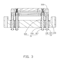
- FIG. 3 illustrates a cross-sectional view of the positioning device of FIG. 1 along a line III-III.
- FIG. 4 illustrates an isometric, partial view of the positioning device of FIG. 1 in operation.
- Coupled is defined as connected, whether directly or indirectly through intervening components, and is not necessarily limited to physical connections.
- the connection can be such that the objects are permanently connected or releasably connected.
- substantially is defined to be essentially conforming to the particular dimension, shape, or other feature that the term modifies, such that the component need not be exact.
- substantially cylindrical means that the object resembles a cylinder, but can have one or more deviations from a true cylinder.
- comprising when utilized, means “including, but not necessarily limited to”; it specifically indicates open-ended inclusion or membership in the so-described combination, group, series and the like.
- a positioning device can include a fixing mechanism, a first positioning assembly, a second positioning assembly.
- the fixing mechanism include a base, a first moving member movably passing through the base, and a second moving member movably passing through the base.
- the first positioning assembly includes a bottom board and two first guide portions separately protruding from the bottom board. Each first guide portion forms one first incline surface.
- the second positioning assembly is positioned above bottom board away from the base.
- the second positioning assembly can include a base body and two second guide portions.
- the base body is positioned between the two first guide portions respectively positioned on opposite side surfaces of the base body. Each second guide portion forms a guiding surface.
- the first moving member is fixed with the bottom board at one end away from the base.
- the second moving member is fixed with the base body at one end away from the base.
- FIG. 1 illustrates a positioning device 100 for positioning a workpiece 200 .
- a positioning hole 210 can be defined in the workpiece 200 .
- Each positioning hole 210 can be in a substantially rectangular shape.
- the workpiece 200 can include four sidewalls.
- the four sidewalls can be a first sidewall 211 , a second sidewall 212 , a third sidewall 213 , and a fourth sidewall 214 .
- the first sidewall 211 , the second sidewall 212 , the third sidewall 213 , and the fourth sidewall 214 can cooperatively form the position hole 210 .
- the positioning device 100 can extend into the positioning hole 210 to position the workpiece 200 .
- the positioning device 100 can include a fixing mechanism 10 , a first positioning assembly 30 mounted on the fixing mechanism 10 , a second positioning assembly 50 positioned above the first positioning assembly 30 . Both the first positioning assembly 30 and the second positioning assembly 50 can be movably coupled to the fixing mechanism 10 .
- the fixing mechanism 10 can include a base 11 , two first moving assemblies 13 (as shown in FIG. 3 ), and two second moving assemblies 16 (as shown in FIG. 3 ).
- the first moving assemblies 13 and the second moving assemblies 16 can be movably mounted on the base 11 .
- the base 11 can include a seat 110 and four guiding members 115 received in the seat 110 .
- the seat 110 can include a main body 111 and two extending portions 113 extending from the main body 111 .
- the extending portions 113 can be configured for coupling with a worktable of a machine tool (not shown) or the like.
- the guiding members 115 are linear bearings; the four guiding members 115 can include two first guiding members 1151 and two second guiding members 1153 .
- One first guiding member 1151 and one second guiding member 1153 can be positioned adjacent to one extending portion 113 .
- Another one first guiding member 1151 and another one second guiding member 1153 can be positioned adjacent to another extending portion 113 .
- the two second guiding members 1151 can be positioned between the two first guiding members 1153 .
- the four guiding members 115 can be arranged in line, four central axes of the guiding members 115 can be in a same plane.
- each first moving assembly 13 can include a first moving member 130 , a first elastic member 133 , and a first snap ring 137 .
- Each first moving member 130 can pass through one respective first guiding member 1151 .
- Two ends of each first moving member 130 can be positioned outside of the main body 111 .
- Each first elastic member 133 can sleeve on the first moving member 130 at first end portion of the one respective first moving member 130 .
- the first snap ring 137 can be clamped on a second end portion of the one respective first moving member 130 .
- a structure of each second moving assembly 16 can be same as each first moving assembly 13 .
- Each second moving assembly 16 can include a second moving member 160 , a second elastic member 163 , and a second snap ring 167 .
- Each second moving member 160 can pass through one respective second guiding member 1153 .
- Two ends of each second moving member 160 can be positioned outside of the main body 111 .
- Each second elastic member 163 can sleeve on the second moving member 160 at a first end portion of one respective second moving member 160 .
- the second snap ring 167 can be clamped on a second end portion of the one respective second moving member 160 .
- the elastic member 133 and the elastic member 163 are elastic springs.
- the elastic member 133 , the elastic member 163 can be elastic sleeves or elastic pieces.
- the first positioning assembly 30 can include a first mounting member 31 and a first guide block 33 fixed with the first mounting member 31 .
- Four first through holes 310 can be separately defined in the first mounting member 31 corresponding to the first moving assemblies 13 and the second moving assemblies 16 .
- One end of each first moving member 130 away from the main body 111 can pass through one first through hole 310 , such that each first elastic member 133 can be resisted between the main body 111 and the first mounting member 31 .
- One end of each second moving member 160 away from the main body 111 can be received in one first through hole 310 , such that each first elastic member 133 can resist between the one respective first guiding member 1151 and the first mounting member 31 .
- the first guide block 33 can include a bottom board 330 and two first guide portions 335 separately protruding from the bottom board 330 .
- Two second through holes 333 corresponding to the two first moving assemblies 13 and the third through holes 334 corresponding to the two second moving assemblies 16 can be defined in the first guide block 33 .
- Each second through hole 333 can be defined at one first guide portion 335 and the base board 330 .
- Two third through holes 334 can be defined in the base board 330 and positioned between the two first guide portions 335 .
- Each first moving member 130 can movably pass through one second through hole 333 .
- Each second moving member 160 can movably pass through one third through hole 334 .
- Each first guide portion 335 can include a first surface 3350 , a vertical surface 3351 , a first incline surface 3353 , a second incline surface 3355 , and a third incline surface 3357 .
- the first surface 3350 can be substantially parallel to the bottom board 330 .
- the vertical surface 3351 can be substantially perpendicularly coupled between the first surface 3350 and the bottom board 330 .
- the vertical surface 3351 can be opposite to the first incline surface 3353 .
- the vertical surface 3351 can be coupled between the second incline surface 3355 and the third incline surface 3357 .
- Two vertical surfaces of the two first guide portions 335 can be face to face.
- a first joint edge 3358 can be formed between the vertical surface 3351 and the first surface 3350 .
- a second joint edge 3359 can be formed between the incline surface 3353 and the first surface 3350 .
- a first angle formed between the first incline surface 3353 and the bottom board 330 can be greater than or equal to 75 degrees.
- a second angle can be formed between the second incline surface 3355 and the bottom board 330 can be greater than or equal to 75 degrees.
- a third angle can be formed between the third incline surface 3357 and the bottom board 330 can be greater than or equal to 75 degrees.
- the first guide block 33 can be made of plastic steel.
- the second positioning assembly 50 can include a second mounting member 51 and a second guide block 53 fixedly mounted on the second mounting member 51 .
- the second mounting member 51 can be positioned on the bottom board 330 and located between the two first guide portions 335 .
- Two fourth through holes 510 can be defined in the second mounting member 51 corresponding to the two second moving member 160 .
- An end of each second moving member 160 away from main body 111 can be received and fixed in one respective fourth through hole 510 , thereby the second elastic members 160 can be resisted between the second mounting member 51 and the one respective second guiding member 115 .
- the second guide block 53 can include a base body 55 and four wedged-shaped second guide portions 58 protruding from the base body 55 .
- the base body 55 can include two end surfaces 550 , a second surface 551 , a third surface 553 , and a fourth surface 556 .
- Each end surface 550 can be opposite to one vertical surface 3351 .
- the second surface 551 can be substantially parallel to and away from the second mounting member 51 .
- the second surface 551 can be coupled between the third surface 553 and the fourth surface 556 .
- a third joint edge 5510 can be formed between each end surface 550 and the second surface 551 .
- the third joint edges 5510 can be parallel to the first joint edge 3358 .
- a length of each third joint edge 5510 can be greater than lengths of the first joint edge 3358 and the second joint edge 3359 .
- Two separate fifth through holes 558 can be defined in the base body 55 .
- One end of each second moving member 160 away from the seat 110 can be received in one fifth through hole 558 .
- Two wedged-shaped second guide portions 58 can be respectively positioned on two ends of the third surface 553 .
- Other two wedged-shaped second guide portion 58 can be respectively positioned on two ends of the fourth surface 556 .
- a guiding surface 580 can be formed on each wedged-shaped second guide portion 335 (as shown in FIG. 1 ).
- An inclining direction of guiding surfaces 580 positioned on the third surface 553 can be same as the second incline surface 3355 .
- An inclining direction of the guiding surfaces 580 positioned on the fourth surface 556 can be same as the third incline surface 3357 .
- An angle formed between each guiding surface 580 and the base body 55 can be less than or equal to 15 degrees. In other embodiments, the number of the guiding surface 580 can be two, or more.
- the guiding members 115 can be positioned in the base 11 , the first moving members 130 and the second moving members 160 can pass through corresponding guiding members 115 , respectively.
- Each first elastic member 133 can be sleeve on one first moving member 130 .
- Each second elastic member 160 can sleeve on one second moving member 160 .
- the first mounting member 31 can be fixed with the first guide block 33 .
- the second mounting member 51 can be fixed with the second guide block 53 .
- the first mounting member 31 and the first guide block 33 can be fixedly sleeved on the first moving members 130 and the second moving members 160 .
- Each first elastic member 133 can resist between one first guiding member 1151 and the first mounting member 31 .
- the second mounting member 51 and the second guide block 53 can be fixedly sleeved on the second moving members 160 .
- Each second elastic member 163 can resist between the second mounting member 51 and one second guiding member 1153 .
- the first snap ring 137 and second snap ring 167 can be clamped with the first moving members 130 and the second moving members 160 , respectively.
- the positioning device 100 can be fixed on one worktable.
- the workpiece 200 will slide relative to the first guide blocks 33 along the second guide portions 335 because of the workpiece 200 own weight, when the positioning hole 210 is aligned with the first positioning assembly 30 and the second positioning assembly 35 in line.
- the two first incline surfaces 3353 will limit motions of the workpiece 200 along a direction substantially parallel to the second sidewall 212 .
- the four guiding surfaces 580 can limit motions of the workpiece 200 along a direction substantially parallel to the first sidewall 211 .
- the first positioning assembly 30 can be pressed downward the seat 110 , then two guiding surfaces 580 resist against the second sidewall 212 and other two guiding surfaces 580 resist against the fourth sidewall 214 for limiting motions along the direction substantially parallel to the first sidewall 211 .
- Each first elastic member 133 resists corresponding one first positioning assembly 30 to enable the two first guide portions 335 stretch into the positioning hole 210 .
- the first sidewall 211 can resist against the first incline surfaces 3353
- the third sidewall 212 can resist against the first incline surfaces 3353 for limiting motions of the workpiece 200 along the direction substantially parallel to the second sidewall 212 .
- the positioning hole 210 are not arranged with the second guide blocks 53 in line, thus the second sidewall 212 and the fourth sidewall 214 deviate from corresponding one guiding surface 3353 .
- a position of the workpiece 200 can be adjusted along the first sidewall 211 , then the second guide block 53 can extend into the positioning hole 210 , and the second sidewall 212 and the fourth sidewall 214 resist against the fourth guiding surfaces 580 to position the workpiece 200 .
- the first positioning assembly 30 and the second positioning assembly 50 can be separately positioned in the positioning device 100 .
- the two first incline surface 3353 can be configured for limiting motions of the workpiece 200 along the direction substantially parallel to the second sidewall 212 .
- the four guiding surfaces 580 can be configured for limiting motions of the workpiece 200 along the direction substantially parallel to the first sidewall 211 .
- the extending portions 113 can be omitted.
- the main body 111 can be directly assembled with the worktable or the like in use.
- the guiding members 115 can be omitted, the first moving member 130 and the second moving member 160 can directly pass through the main body 111 .
- the first mounting member 31 can be omitted, the first moving member 130 and the second moving member 160 directly assembled to the first guide block 33 .
- the second mounting member 51 can be omitted, and the second moving member 160 directly assembled to the second guide block 53 .
- the first guide block 33 and the second guide block 53 can be made of other material, not limit to the plastic steel.
- the positioning hole 210 can be not limited to a rectangular hole, the positioning hole 210 can be in a circular, or triangle, or polygon, or other shapes.
- the first incline surface 3353 and the guiding surfaces 580 can be designed to fit over sidewalls of the positioning hole 210 , and the positioning device 100 can clamp lower end of the sidewalls of the positioning hole 210 for limiting motions of the workpiece 200 .
- the number of the guiding surfaces 580 can be at least two, the at least two guiding surfaces 580 are respectively positioned on opposite two side surfaces of the base body 55 .
Landscapes
- Engineering & Computer Science (AREA)
- Mechanical Engineering (AREA)
- Jigs For Machine Tools (AREA)
- Container, Conveyance, Adherence, Positioning, Of Wafer (AREA)
- Machine Tool Units (AREA)
- Automatic Assembly (AREA)
Abstract
Description
Claims (16)
Applications Claiming Priority (3)
| Application Number | Priority Date | Filing Date | Title |
|---|---|---|---|
| CN201310543297 | 2013-11-06 | ||
| CN201310543297.1A CN104625992B (en) | 2013-11-06 | 2013-11-06 | Positioner |
| CN201310543297.1 | 2013-11-06 |
Publications (2)
| Publication Number | Publication Date |
|---|---|
| US20150123333A1 US20150123333A1 (en) | 2015-05-07 |
| US9475162B2 true US9475162B2 (en) | 2016-10-25 |
Family
ID=53006466
Family Applications (1)
| Application Number | Title | Priority Date | Filing Date |
|---|---|---|---|
| US14/534,367 Expired - Fee Related US9475162B2 (en) | 2013-11-06 | 2014-11-06 | Positioning device |
Country Status (3)
| Country | Link |
|---|---|
| US (1) | US9475162B2 (en) |
| CN (1) | CN104625992B (en) |
| TW (1) | TWI608905B (en) |
Families Citing this family (2)
| Publication number | Priority date | Publication date | Assignee | Title |
|---|---|---|---|---|
| CN106984910B (en) * | 2017-05-12 | 2019-06-04 | 江苏凯尔生物识别科技有限公司 | a welding jig |
| CN112719967B (en) * | 2019-10-14 | 2022-07-29 | 富鼎电子科技(嘉善)有限公司 | Positioning structure |
Citations (20)
| Publication number | Priority date | Publication date | Assignee | Title |
|---|---|---|---|---|
| US2261055A (en) * | 1940-07-30 | 1941-10-28 | Ira J Dulaney | Watch movement holder |
| US2271879A (en) * | 1941-11-04 | 1942-02-03 | Monogram Mfg Co | Clamp |
| US2385180A (en) * | 1943-09-30 | 1945-09-18 | Camloc Fastener Corp | Fastener |
| US3064715A (en) * | 1960-08-17 | 1962-11-20 | Richard E Bland | Bonding jig |
| US3218058A (en) * | 1964-02-17 | 1965-11-16 | Monogram Ind Inc | Quick adjustable clamp |
| US3518745A (en) * | 1967-12-27 | 1970-07-07 | Northrop Corp | Installation tool |
| US3612507A (en) * | 1969-12-18 | 1971-10-12 | Phillips Petroleum Co | Valve assembling apparatus |
| US4397094A (en) * | 1979-12-01 | 1983-08-09 | Futaba Denshi Kogyo K.K. | Apparatus for positioning and aligning dies |
| US4570320A (en) * | 1985-01-14 | 1986-02-18 | Kile Walter F | Tool for aligning engine cylinder heads |
| US5062200A (en) * | 1987-04-01 | 1991-11-05 | Aspera S.R.L. | Device for the assembly of small electrical machines |
| US5566840A (en) * | 1993-11-12 | 1996-10-22 | Multiline International Europa L.P. | Device for aligning printed circuit boards and pattern carriers |
| US6293534B1 (en) * | 2000-04-12 | 2001-09-25 | David F. Leban | Support device with floating pins |
| US6412768B1 (en) * | 1999-09-01 | 2002-07-02 | Micron Technology, Inc. | Self-adjusting printed circuit board support and method of use |
| US7003827B2 (en) * | 2004-06-21 | 2006-02-28 | Innovative Medical Products Inc. | Operating table support clamp |
| US20080203644A1 (en) * | 2007-02-28 | 2008-08-28 | Dasilva Manuel F | Operating table support clamp |
| US7634853B2 (en) * | 2005-07-15 | 2009-12-22 | Advanced Precision Machining, Inc. | Apparatus for precisely aligning and securing plural plates together |
| US20100276859A1 (en) * | 2009-04-30 | 2010-11-04 | Maciejewski Wendell C | Head window fixture and method |
| US20110167604A1 (en) * | 2010-01-12 | 2011-07-14 | Stewart Thomas D | Fixture for aligning and installing drawer fronts/faces to drawer boxes |
| US20120321379A1 (en) * | 2011-06-14 | 2012-12-20 | Hon Hai Precision Industry Co., Ltd. | Locking structure |
| US8608148B2 (en) * | 2009-09-04 | 2013-12-17 | Uhlmann Pac-Systeme Gmbh & Co. Kg | Tool holder, tool, and workstation with tool holder and tool attached thereto |
Family Cites Families (17)
| Publication number | Priority date | Publication date | Assignee | Title |
|---|---|---|---|---|
| US5692357A (en) * | 1993-06-10 | 1997-12-02 | Mccain; Maurice | Adjustable template and jig |
| US5695600A (en) * | 1994-10-03 | 1997-12-09 | Goin; Bobby Gene | Vacuum table for decal weeding |
| IT1279409B1 (en) * | 1995-11-13 | 1997-12-10 | Fk Systema S R L | MODULAR BLOCK FOR THE FORMATION OF SUCTION TABLES IN MACHINES FOR CUTTING FABRICS WITH AN ALTERNATIVE MOVING BLADE |
| IT1283019B1 (en) * | 1996-05-16 | 1998-04-03 | Salvagnini Italia Spa | MANAGEMENT METHOD OF A WORKING ISLAND INCLUDING A ROBOT SUBJECTED TO A BENDING PRESS FOR PROCESSING SHEETS. |
| DE29718643U1 (en) * | 1997-10-21 | 1997-12-11 | Tünkers Maschinenbau GmbH, 40880 Ratingen | Combined centering and tensioning device which can be actuated by pressure medium, in particular for use in body construction in the motor vehicle industry |
| DE19831064C2 (en) * | 1998-07-10 | 2000-05-18 | Bosch Gmbh Robert | Device for holding components made of ferromagnetic material |
| CN1104999C (en) * | 1999-04-28 | 2003-04-09 | Smc株式会社 | Clamping device |
| JP3634190B2 (en) * | 1999-05-24 | 2005-03-30 | Smc株式会社 | Clamping device |
| CN2409190Y (en) * | 1999-11-17 | 2000-12-06 | 崔学发 | Hand vacuum sucker special tool device for free-grabbing and inserting |
| CN2407886Y (en) * | 2000-02-21 | 2000-11-29 | 曾绍谦 | Labor-saving convenience clip |
| JP4118145B2 (en) * | 2002-02-22 | 2008-07-16 | 株式会社コスメック | Automatic positioning device |
| US8087650B2 (en) * | 2004-03-08 | 2012-01-03 | Pascal Engineering Corporation | Clamping device |
| CN2759697Y (en) * | 2004-12-29 | 2006-02-22 | 比亚迪股份有限公司 | Clamping apparatus |
| JP4954899B2 (en) * | 2005-12-27 | 2012-06-20 | 株式会社コスメック | Positioning device and positioning system |
| TWI451943B (en) * | 2009-08-10 | 2014-09-11 | Hon Hai Prec Ind Co Ltd | Fixture |
| CN202292195U (en) * | 2011-10-31 | 2012-07-04 | 南通爱慕希机械有限公司 | Hole-locating jig |
| TWM441542U (en) * | 2012-04-13 | 2012-11-21 | Shu-Qi Liao | Auxiliary block structure for workbench |
-
2013
- 2013-11-06 CN CN201310543297.1A patent/CN104625992B/en not_active Expired - Fee Related
- 2013-11-18 TW TW102141959A patent/TWI608905B/en not_active IP Right Cessation
-
2014
- 2014-11-06 US US14/534,367 patent/US9475162B2/en not_active Expired - Fee Related
Patent Citations (20)
| Publication number | Priority date | Publication date | Assignee | Title |
|---|---|---|---|---|
| US2261055A (en) * | 1940-07-30 | 1941-10-28 | Ira J Dulaney | Watch movement holder |
| US2271879A (en) * | 1941-11-04 | 1942-02-03 | Monogram Mfg Co | Clamp |
| US2385180A (en) * | 1943-09-30 | 1945-09-18 | Camloc Fastener Corp | Fastener |
| US3064715A (en) * | 1960-08-17 | 1962-11-20 | Richard E Bland | Bonding jig |
| US3218058A (en) * | 1964-02-17 | 1965-11-16 | Monogram Ind Inc | Quick adjustable clamp |
| US3518745A (en) * | 1967-12-27 | 1970-07-07 | Northrop Corp | Installation tool |
| US3612507A (en) * | 1969-12-18 | 1971-10-12 | Phillips Petroleum Co | Valve assembling apparatus |
| US4397094A (en) * | 1979-12-01 | 1983-08-09 | Futaba Denshi Kogyo K.K. | Apparatus for positioning and aligning dies |
| US4570320A (en) * | 1985-01-14 | 1986-02-18 | Kile Walter F | Tool for aligning engine cylinder heads |
| US5062200A (en) * | 1987-04-01 | 1991-11-05 | Aspera S.R.L. | Device for the assembly of small electrical machines |
| US5566840A (en) * | 1993-11-12 | 1996-10-22 | Multiline International Europa L.P. | Device for aligning printed circuit boards and pattern carriers |
| US6412768B1 (en) * | 1999-09-01 | 2002-07-02 | Micron Technology, Inc. | Self-adjusting printed circuit board support and method of use |
| US6293534B1 (en) * | 2000-04-12 | 2001-09-25 | David F. Leban | Support device with floating pins |
| US7003827B2 (en) * | 2004-06-21 | 2006-02-28 | Innovative Medical Products Inc. | Operating table support clamp |
| US7634853B2 (en) * | 2005-07-15 | 2009-12-22 | Advanced Precision Machining, Inc. | Apparatus for precisely aligning and securing plural plates together |
| US20080203644A1 (en) * | 2007-02-28 | 2008-08-28 | Dasilva Manuel F | Operating table support clamp |
| US20100276859A1 (en) * | 2009-04-30 | 2010-11-04 | Maciejewski Wendell C | Head window fixture and method |
| US8608148B2 (en) * | 2009-09-04 | 2013-12-17 | Uhlmann Pac-Systeme Gmbh & Co. Kg | Tool holder, tool, and workstation with tool holder and tool attached thereto |
| US20110167604A1 (en) * | 2010-01-12 | 2011-07-14 | Stewart Thomas D | Fixture for aligning and installing drawer fronts/faces to drawer boxes |
| US20120321379A1 (en) * | 2011-06-14 | 2012-12-20 | Hon Hai Precision Industry Co., Ltd. | Locking structure |
Also Published As
| Publication number | Publication date |
|---|---|
| US20150123333A1 (en) | 2015-05-07 |
| CN104625992B (en) | 2017-12-05 |
| TWI608905B (en) | 2017-12-21 |
| TW201518039A (en) | 2015-05-16 |
| CN104625992A (en) | 2015-05-20 |
Similar Documents
| Publication | Publication Date | Title |
|---|---|---|
| US9233474B2 (en) | Clamping apparatus | |
| US9802284B2 (en) | Clamping device | |
| US20130084784A1 (en) | Pressure detection device and polishing apparatus | |
| US9033327B2 (en) | Adjustment mechanism | |
| US9523565B2 (en) | Measuring device | |
| US20160195380A1 (en) | Positioning device | |
| US20150063964A1 (en) | Overturning machine and workbench thereof | |
| US9381596B2 (en) | Welding fixture | |
| US20150071719A1 (en) | Feeding device and machine tool using the same | |
| US9975213B2 (en) | Polishing apparatus | |
| US10486275B2 (en) | Processing mechanism | |
| US20150059502A1 (en) | Clamping apparatus | |
| US9475162B2 (en) | Positioning device | |
| US20150165595A1 (en) | Clamping device | |
| US9205523B2 (en) | Positioning apparatus | |
| US9770797B2 (en) | Tool positioning and holding mechanism | |
| US9618141B2 (en) | Assembly of cable and cable support device | |
| CN205325274U (en) | fixture | |
| US10112276B2 (en) | Press mechanism | |
| US20150273702A1 (en) | Mechanical arm structure and plate | |
| CN108581073B (en) | Clamping mechanism and pipe bending equipment with same | |
| CN206366934U (en) | A kind of clamp system based on spring | |
| KR101283131B1 (en) | Pipe supply apparatus pipe side facing machine | |
| CN107309472A (en) | A kind of cylindrical workpiece hole drilling die | |
| US20130028654A1 (en) | Clamping assembly that acts as an interface between two components |
Legal Events
| Date | Code | Title | Description |
|---|---|---|---|
| AS | Assignment |
Owner name: FU TAI HUA INDUSTRY (SHENZHEN) CO., LTD., CHINA Free format text: ASSIGNMENT OF ASSIGNORS INTEREST;ASSIGNORS:CHANG, HSIU-LUNG;YANG, WEI;HU, KE;AND OTHERS;REEL/FRAME:034116/0876 Effective date: 20141029 Owner name: HON HAI PRECISION INDUSTRY CO., LTD., TAIWAN Free format text: ASSIGNMENT OF ASSIGNORS INTEREST;ASSIGNORS:CHANG, HSIU-LUNG;YANG, WEI;HU, KE;AND OTHERS;REEL/FRAME:034116/0876 Effective date: 20141029 |
|
| ZAAA | Notice of allowance and fees due |
Free format text: ORIGINAL CODE: NOA |
|
| ZAAB | Notice of allowance mailed |
Free format text: ORIGINAL CODE: MN/=. |
|
| STCF | Information on status: patent grant |
Free format text: PATENTED CASE |
|
| MAFP | Maintenance fee payment |
Free format text: PAYMENT OF MAINTENANCE FEE, 4TH YEAR, LARGE ENTITY (ORIGINAL EVENT CODE: M1551); ENTITY STATUS OF PATENT OWNER: LARGE ENTITY Year of fee payment: 4 |
|
| FEPP | Fee payment procedure |
Free format text: MAINTENANCE FEE REMINDER MAILED (ORIGINAL EVENT CODE: REM.); ENTITY STATUS OF PATENT OWNER: LARGE ENTITY |
|
| LAPS | Lapse for failure to pay maintenance fees |
Free format text: PATENT EXPIRED FOR FAILURE TO PAY MAINTENANCE FEES (ORIGINAL EVENT CODE: EXP.); ENTITY STATUS OF PATENT OWNER: LARGE ENTITY |
|
| STCH | Information on status: patent discontinuation |
Free format text: PATENT EXPIRED DUE TO NONPAYMENT OF MAINTENANCE FEES UNDER 37 CFR 1.362 |
|
| FP | Lapsed due to failure to pay maintenance fee |
Effective date: 20241025 |