US9471297B2 - Methods and apparatus for uninstalling a software application - Google Patents
Methods and apparatus for uninstalling a software application Download PDFInfo
- Publication number
- US9471297B2 US9471297B2 US14/482,831 US201414482831A US9471297B2 US 9471297 B2 US9471297 B2 US 9471297B2 US 201414482831 A US201414482831 A US 201414482831A US 9471297 B2 US9471297 B2 US 9471297B2
- Authority
- US
- United States
- Prior art keywords
- software objects
- software
- deleted
- user
- objects
- Prior art date
- Legal status (The legal status is an assumption and is not a legal conclusion. Google has not performed a legal analysis and makes no representation as to the accuracy of the status listed.)
- Active
Links
Images


Classifications
-
- G—PHYSICS
- G06—COMPUTING; CALCULATING OR COUNTING
- G06F—ELECTRIC DIGITAL DATA PROCESSING
- G06F8/00—Arrangements for software engineering
- G06F8/60—Software deployment
- G06F8/61—Installation
- G06F8/62—Uninstallation
-
- G—PHYSICS
- G06—COMPUTING; CALCULATING OR COUNTING
- G06F—ELECTRIC DIGITAL DATA PROCESSING
- G06F16/00—Information retrieval; Database structures therefor; File system structures therefor
- G06F16/20—Information retrieval; Database structures therefor; File system structures therefor of structured data, e.g. relational data
- G06F16/24—Querying
- G06F16/245—Query processing
- G06F16/2455—Query execution
-
- G06F17/30477—
Definitions
- the present disclosure relates in general to databases, and, in particular, to methods and apparatus for uninstalling a software application.
- Software applications typically include a plurality of software objects. Often, two or more software applications will share one or more software objects. Current methods of removing applications are inefficient and error-prone. In one method, an application and all of the objects associated with it are simply deleted from the environment without regard for any other applications that might be associated with the same underlying objects. Any applications that reference the deleted application or objects must also be deleted and then reinstalled.
- a user In another method, a user must painstakingly select each object to be deleted, and can only be sure that his selections are correct through a time-consuming process of trial and error. Further, once the appropriate objects have been identified, deleting them on the back-end may not completely remove the application from the workspace. This inability to efficiently and effectively delete applications can clutter the workspace, contribute to system instability, and complicate the debugging process.
- FIG. 1 is a block diagram of an example network communication system.
- FIG. 2 is a block diagram of an example computing device.
- FIG. 3 is a flowchart of an example process for uninstalling a software application.
- FIG. 4 is a screenshot of an example uninstall application.
- FIG. 5 is an enlarged view of the application tree of FIG. 4 .
- FIG. 6 is an enlarged view of uninstall command buttons of FIG. 4 .
- FIG. 7 is another screenshot of the example uninstall application of FIG. 4 after a validation cycle has been executed.
- FIG. 8 is an enlarged view of the locked report and the unlocked report of the screenshot of FIG. 7 .
- a database is queried to determine a plurality of software objects that are associated with the selected application.
- the system displays a plurality of relationships between the plurality of software objects (e.g., a tree view with check boxes to select and unselect objects).
- the display indicates which software objects in the plurality of software objects can be deleted without affecting other software objects in the plurality of software objects.
- the display indicates which software objects in the plurality of software objects cannot be deleted without affecting other software objects in the plurality of software objects. Based on these results, the user then determines a new list of objects to keep and objects to delete. This process is repeated until the user approves the list and deletes the application.
- FIG. 1 A block diagram of certain elements of an example network communications system 100 is illustrated in FIG. 1 .
- the illustrated system 100 includes one or more client devices 102 (e.g., computer, television, camera, phone), one or more web servers 106 , and one or more databases 108 .
- client devices 102 e.g., computer, television, camera, phone
- web servers 106 e.g., web servers
- databases 108 e.g., a server
- Each of these devices may communicate with each other via a connection to one or more communications channels 110 such as the Internet or some other wired and/or wireless data network, including, but not limited to, any suitable wide area network or local area network.
- any of the devices described herein may be directly connected to each other instead of over a network.
- the web server 106 stores a plurality of files, programs, and/or web pages in one or more databases 108 for use by the client devices 102 as described in detail below.
- the database 108 may be connected directly to the web server 106 and/or via one or more network connections.
- the database 108 stores data as described in detail below.
- Each server 106 may interact with a large number of client devices 102 . Accordingly, each server 106 is typically a high end computer with a large storage capacity, one or more fast microprocessors, and one or more high speed network connections. Conversely, relative to a typical server 106 , each client device 102 typically includes less storage capacity, a single microprocessor, and a single network connection.
- user 114 a is using client device 102 a and client device 102 b .
- user 114 a may be reviewing documents displayed on a desktop display of client device 102 a and coding those documents using a touch screen on client device 102 b.
- FIG. 2 is a block diagram of an example computing device.
- the example computing device 200 includes a main unit 202 which may include, if desired, one or more processing units 204 electrically coupled by an address/data bus 206 to one or more memories 208 , other computer circuitry 210 , and one or more interface circuits 212 .
- the processing unit 204 may include any suitable processor or plurality of processors.
- the processing unit 204 may include other components that support the one or more processors.
- the processing unit 204 may include a central processing unit (CPU), a graphics processing unit (GPU), and/or a direct memory access (DMA) unit.
- CPU central processing unit
- GPU graphics processing unit
- DMA direct memory access
- the memory 208 may include various types of non-transitory memory including volatile memory and/or non-volatile memory such as, but not limited to, distributed memory, read-only memory (ROM), random access memory (RAM) etc.
- the memory 208 typically stores a software program that interacts with the other devices in the system as described herein. This program may be executed by the processing unit 204 in any suitable manner.
- the memory 208 may also store digital data indicative of documents, files, programs, web pages, etc. retrieved from a server and/or loaded via an input device 214 .
- the interface circuit 212 may be implemented using any suitable interface standard, such as an Ethernet interface and/or a Universal Serial Bus (USB) interface.
- One or more input devices 214 may be connected to the interface circuit 212 for entering data and commands into the main unit 202 .
- the input device 214 may be a keyboard, mouse, touch screen, track pad, camera, voice recognition system, accelerometer, global positioning system (GPS), and/or any other suitable input device.
- One or more displays, printers, speakers, monitors, televisions, high definition televisions, and/or other suitable output devices 216 may also be connected to the main unit 202 via the interface circuit 212 .
- One or more storage devices 218 may also be connected to the main unit 202 via the interface circuit 212 .
- a hard drive, CD drive, DVD drive, and/or other storage devices may be connected to the main unit 202 .
- the storage devices 218 may store any type of data used by the device 200 .
- the computing device 200 may also exchange data with one or more input/output (I/O) devices 220 , such as network routers, camera, audio players, thumb drives etc.
- I/O input/output
- the computing device 200 may also exchange data with other network devices 222 via a connection to a network 110 .
- the network connection may be any type of network connection, such as an Ethernet connection, digital subscriber line (DSL), telephone line, coaxial cable, wireless base station 230 , etc.
- Users 114 of the system 100 may be required to register with a server 106 . In such an instance, each user 114 may choose a user identifier (e.g., e-mail address) and a password which may be required for the activation of services.
- the user identifier and password may be passed across the network 110 using encryption built into the user's browser. Alternatively, the user identifier and/or password may be assigned by the server 106 .
- the device 200 may be a wireless device 200 .
- the device 200 may include one or more antennas 224 connected to one or more radio frequency (RF) transceivers 226 .
- the transceiver 226 may include one or more receivers and one or more transmitters operating on the same and/or different frequencies.
- the device 200 may include a blue tooth transceiver 216 , a Wi-Fi transceiver 216 , and diversity cellular transceivers 216 .
- the transceiver 226 allows the device 200 to exchange signals, such as voice, video and any other suitable data, with other wireless devices 228 , such as a phone, camera, monitor, television, and/or high definition television.
- the device 200 may send and receive wireless telephone signals, text messages, audio signals and/or video signals directly and/or via a base station 230 .
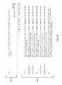
- FIG. 3 is a flowchart of an example process for uninstalling a software application.
- the process 300 may be carried out by one or more suitably programmed processors, such as a CPU executing software (e.g., block 204 of FIG. 2 ).
- the process 300 may also be carried out by hardware or a combination of hardware and hardware executing software.
- Suitable hardware may include one or more application specific integrated circuits (ASICs), state machines, field programmable gate arrays (FPGAs), digital signal processors (DSPs), and/or other suitable hardware.
- ASICs application specific integrated circuits
- FPGAs field programmable gate arrays
- DSPs digital signal processors
- the process 300 begins when a request to uninstall an application is received (block 302 ). For example, a user may select an application to uninstall. Subsequently, a database is queried to determine a plurality of software objects that are associated with the selected application (block 304 ). For example, the system may determine that object B depends on object A.
- the system then displays a plurality of relationships between the plurality of software objects (block 306 ). For example, a tree view showing object B's dependency on object A may be displayed.
- the display indicates which software objects in the plurality of software objects can be deleted without affecting other software objects in the plurality of software objects (block 308 ).
- the display indicates which software objects in the plurality of software objects cannot be deleted without affecting other software objects in the plurality of software objects (block 308 ). For example, two lists of software objects may be displayed.
- the display may also indicate which software objects in the plurality of software objects will be automatically deleted.
- the user then indicates which of a plurality of objects to delete (block 310 ). For example, the user may check certain checkboxes.
- the software application is then uninstalled by deleting the user selected software objects (block 312 ). For example, all of the checked software objects are deleted.
- FIG. 4 is a screenshot of an example uninstall application 400 .
- the uninstall application 400 includes an application tree 402 and uninstall command buttons 404 .
- FIG. 5 is an enlarged view of the application tree 402 of FIG. 4 .
- application A 502 includes object A 504 , which includes various fields 506 , views 508 , layouts 510 , and tabs 512 .
- FIG. 6 is an enlarged view of uninstall command buttons 404 of FIG. 4 .
- the uninstall command buttons 404 include a validate button 406 and a cancel button 408 .
- FIG. 7 is another screenshot of the example uninstall application of FIG. 4 after a validation cycle has been executed.
- a user has pressed the validate button 406 and the system has generated a locked report 702 and an unlocked report 704 .
- an uninstall button 706 has been added to the uninstall command buttons 404 .
- FIG. 8 is an enlarged view of the locked report 702 and the unlocked report 704 of the screenshot of FIG. 7 .
- object C cannot be removed because it is locked by application C. Accordingly, the user may uncheck object C in the application tree 402 and rerun the report by pressing the validate button 406 . Pressing the uninstall button 706 will delete the objects that remain checked in the application tree 402 .
Abstract
Description
Claims (20)
Priority Applications (1)
| Application Number | Priority Date | Filing Date | Title |
|---|---|---|---|
| US14/482,831 US9471297B2 (en) | 2014-09-10 | 2014-09-10 | Methods and apparatus for uninstalling a software application |
Applications Claiming Priority (1)
| Application Number | Priority Date | Filing Date | Title |
|---|---|---|---|
| US14/482,831 US9471297B2 (en) | 2014-09-10 | 2014-09-10 | Methods and apparatus for uninstalling a software application |
Publications (2)
| Publication Number | Publication Date |
|---|---|
| US20160070553A1 US20160070553A1 (en) | 2016-03-10 |
| US9471297B2 true US9471297B2 (en) | 2016-10-18 |
Family
ID=55437591
Family Applications (1)
| Application Number | Title | Priority Date | Filing Date |
|---|---|---|---|
| US14/482,831 Active US9471297B2 (en) | 2014-09-10 | 2014-09-10 | Methods and apparatus for uninstalling a software application |
Country Status (1)
| Country | Link |
|---|---|
| US (1) | US9471297B2 (en) |
Cited By (2)
| Publication number | Priority date | Publication date | Assignee | Title |
|---|---|---|---|---|
| US10067753B2 (en) * | 2014-07-21 | 2018-09-04 | Beijing Kingsoft Internet Security Software Co., Ltd. | Application program uninstallation method and apparatus |
| CN109739519A (en) * | 2018-12-26 | 2019-05-10 | 惠州Tcl移动通信有限公司 | Mobile terminal and its discharging method of preset application program, memory |
Families Citing this family (3)
| Publication number | Priority date | Publication date | Assignee | Title |
|---|---|---|---|---|
| CN106254644A (en) * | 2016-07-29 | 2016-12-21 | 努比亚技术有限公司 | Application discharge mechanism and method |
| JP6890410B2 (en) * | 2016-12-16 | 2021-06-18 | キヤノン株式会社 | Information processing equipment and application management methods and programs |
| CN109033327B (en) * | 2018-07-19 | 2021-09-28 | 浪潮软件股份有限公司 | Management system and management method of Chinese address tree |
Citations (8)
| Publication number | Priority date | Publication date | Assignee | Title |
|---|---|---|---|---|
| US5933647A (en) * | 1997-01-24 | 1999-08-03 | Cognet Corporation | System and method for software distribution and desktop management in a computer network environment |
| US6442754B1 (en) * | 1999-03-29 | 2002-08-27 | International Business Machines Corporation | System, method, and program for checking dependencies of installed software components during installation or uninstallation of software |
| US6687902B1 (en) * | 1999-08-05 | 2004-02-03 | International Business Machines Corporation | Method, system, and program for deleting user selected file sets of a program |
| US20040064458A1 (en) * | 2002-10-01 | 2004-04-01 | Richard Hagarty | Deletion objector for determining whether or not to delete an object from an application |
| US6910208B1 (en) * | 2000-04-25 | 2005-06-21 | Microsoft Corporation | System and method of providing replaceable and extensible user interface for the installation of a suite of applications |
| US20050289513A1 (en) * | 2004-06-17 | 2005-12-29 | International Business Machines Corporation | Matrix pattern match techniques for uninstalling multiple dependent components |
| US20080270444A1 (en) * | 2007-04-24 | 2008-10-30 | International Business Machines Corporation | System, method and tool for web-based interactive graphical visualization and authoring of relationships |
| US20110202915A1 (en) * | 2010-02-18 | 2011-08-18 | Kuroyanagi Tomohiro | Program management system, program management method, client, and computer program product |
-
2014
- 2014-09-10 US US14/482,831 patent/US9471297B2/en active Active
Patent Citations (8)
| Publication number | Priority date | Publication date | Assignee | Title |
|---|---|---|---|---|
| US5933647A (en) * | 1997-01-24 | 1999-08-03 | Cognet Corporation | System and method for software distribution and desktop management in a computer network environment |
| US6442754B1 (en) * | 1999-03-29 | 2002-08-27 | International Business Machines Corporation | System, method, and program for checking dependencies of installed software components during installation or uninstallation of software |
| US6687902B1 (en) * | 1999-08-05 | 2004-02-03 | International Business Machines Corporation | Method, system, and program for deleting user selected file sets of a program |
| US6910208B1 (en) * | 2000-04-25 | 2005-06-21 | Microsoft Corporation | System and method of providing replaceable and extensible user interface for the installation of a suite of applications |
| US20040064458A1 (en) * | 2002-10-01 | 2004-04-01 | Richard Hagarty | Deletion objector for determining whether or not to delete an object from an application |
| US20050289513A1 (en) * | 2004-06-17 | 2005-12-29 | International Business Machines Corporation | Matrix pattern match techniques for uninstalling multiple dependent components |
| US20080270444A1 (en) * | 2007-04-24 | 2008-10-30 | International Business Machines Corporation | System, method and tool for web-based interactive graphical visualization and authoring of relationships |
| US20110202915A1 (en) * | 2010-02-18 | 2011-08-18 | Kuroyanagi Tomohiro | Program management system, program management method, client, and computer program product |
Cited By (3)
| Publication number | Priority date | Publication date | Assignee | Title |
|---|---|---|---|---|
| US10067753B2 (en) * | 2014-07-21 | 2018-09-04 | Beijing Kingsoft Internet Security Software Co., Ltd. | Application program uninstallation method and apparatus |
| CN109739519A (en) * | 2018-12-26 | 2019-05-10 | 惠州Tcl移动通信有限公司 | Mobile terminal and its discharging method of preset application program, memory |
| US11928450B2 (en) | 2018-12-26 | 2024-03-12 | Huizhou Tcl Mobile Communication Co., Ltd. | Mobile terminal, method for uninstalling pre-installed application therein, and memory |
Also Published As
| Publication number | Publication date |
|---|---|
| US20160070553A1 (en) | 2016-03-10 |
Similar Documents
| Publication | Publication Date | Title |
|---|---|---|
| JP6967534B2 (en) | Resource allocation for database provisioning | |
| US9471297B2 (en) | Methods and apparatus for uninstalling a software application | |
| US9749257B2 (en) | Method and apparatus for dynamically deploying software agents | |
| CN109815261B (en) | Global search function implementation and data real-time synchronization method and device and electronic equipment | |
| US10462008B2 (en) | Cart mode provisioning of shared computing devices | |
| US20140068026A1 (en) | System for automatically configuring server using pre-recorded configuration script and method thereof | |
| US11720370B2 (en) | Electronic apparatus and method of executing application program | |
| US20200296110A1 (en) | Configurable Feature Level Controls for Data | |
| CN103581878B (en) | A kind of method and apparatus for acquisition target resource in a mobile device | |
| US20160321056A1 (en) | Methods and apparatus for upgrading a plurality of databases | |
| US20190129730A1 (en) | System and method for third party application enablement | |
| US9665605B2 (en) | Methods and apparatus for building a search index for a database | |
| US10282527B2 (en) | Information processing apparatus, information processing method, program, storage medium, and password entry apparatus | |
| US20180375788A1 (en) | Cloud Extensibility Framework | |
| US20160321319A1 (en) | Methods and apparatus for upgrading a plurality of databases | |
| US20150149474A1 (en) | Method and apparatus for indexing and searching documents | |
| CN106254575A (en) | A kind of method and apparatus determining ID | |
| US9536199B1 (en) | Recommendations based on device usage | |
| US20160026614A1 (en) | Methods and apparatus for annotating documents | |
| US20150309972A1 (en) | Methods and apparatus for associating a document with a database field value | |
| US20160321306A1 (en) | Methods and apparatus for upgrading a plurality of databases | |
| US20160196296A1 (en) | Methods and apparatus for deleting a plurality of documents associated with an electronic document review application | |
| TWM509926U (en) | System for automated generation of applications | |
| CN113869032A (en) | Analysis report output method, system, computer and readable storage medium | |
| US20200257677A1 (en) | Method and device for uploading user information, and computer-readable storage medium |
Legal Events
| Date | Code | Title | Description |
|---|---|---|---|
| AS | Assignment |
Owner name: KCURA CORPORATION, ILLINOIS Free format text: ASSIGNMENT OF ASSIGNORS INTEREST;ASSIGNORS:HOGAN, CHRISTOPHER;KAPUZA, NICOLAS P.;MASANEK, MICHAEL P.;AND OTHERS;SIGNING DATES FROM 20140911 TO 20141211;REEL/FRAME:034799/0976 |
|
| AS | Assignment |
Owner name: KCURA LLC, ILLINOIS Free format text: ASSIGNMENT OF ASSIGNORS INTEREST;ASSIGNOR:KCURA CORPORATION;REEL/FRAME:034976/0680 Effective date: 20150128 |
|
| STCF | Information on status: patent grant |
Free format text: PATENTED CASE |
|
| AS | Assignment |
Owner name: RELATIVITY ODA LLC, ILLINOIS Free format text: CHANGE OF NAME;ASSIGNOR:KCURA LLC;REEL/FRAME:043687/0734 Effective date: 20170828 |
|
| FEPP | Fee payment procedure |
Free format text: ENTITY STATUS SET TO UNDISCOUNTED (ORIGINAL EVENT CODE: BIG.); ENTITY STATUS OF PATENT OWNER: LARGE ENTITY |
|
| FEPP | Fee payment procedure |
Free format text: SURCHARGE FOR LATE PAYMENT, LARGE ENTITY (ORIGINAL EVENT CODE: M1554); ENTITY STATUS OF PATENT OWNER: LARGE ENTITY |
|
| MAFP | Maintenance fee payment |
Free format text: PAYMENT OF MAINTENANCE FEE, 4TH YEAR, LARGE ENTITY (ORIGINAL EVENT CODE: M1551); ENTITY STATUS OF PATENT OWNER: LARGE ENTITY Year of fee payment: 4 |
|
| AS | Assignment |
Owner name: OWL ROCK CAPITAL CORPORATION, AS COLLATERAL AGENT, NEW YORK Free format text: SECURITY INTEREST;ASSIGNOR:RELATIVITY ODA LLC;REEL/FRAME:056218/0822 Effective date: 20210512 |
|
| MAFP | Maintenance fee payment |
Free format text: PAYMENT OF MAINTENANCE FEE, 8TH YEAR, LARGE ENTITY (ORIGINAL EVENT CODE: M1552); ENTITY STATUS OF PATENT OWNER: LARGE ENTITY Year of fee payment: 8 |