US9462999B2 - Biopsy sample storage - Google Patents
Biopsy sample storage Download PDFInfo
- Publication number
- US9462999B2 US9462999B2 US13/347,941 US201213347941A US9462999B2 US 9462999 B2 US9462999 B2 US 9462999B2 US 201213347941 A US201213347941 A US 201213347941A US 9462999 B2 US9462999 B2 US 9462999B2
- Authority
- US
- United States
- Prior art keywords
- tissue
- tissue sample
- storage assembly
- sample holder
- rotatable member
- Prior art date
- Legal status (The legal status is an assumption and is not a legal conclusion. Google has not performed a legal analysis and makes no representation as to the accuracy of the status listed.)
- Active, expires
Links
- 238000001574 biopsy Methods 0.000 title claims abstract description 90
- 238000003860 storage Methods 0.000 title claims abstract description 73
- 239000012530 fluid Substances 0.000 claims description 14
- 239000000523 sample Substances 0.000 description 108
- FAPWRFPIFSIZLT-UHFFFAOYSA-M Sodium chloride Chemical compound [Na+].[Cl-] FAPWRFPIFSIZLT-UHFFFAOYSA-M 0.000 description 15
- 239000011780 sodium chloride Substances 0.000 description 15
- 238000000034 method Methods 0.000 description 14
- 238000012546 transfer Methods 0.000 description 14
- 238000004891 communication Methods 0.000 description 8
- 230000033001 locomotion Effects 0.000 description 8
- 238000010304 firing Methods 0.000 description 7
- 230000007246 mechanism Effects 0.000 description 5
- 208000004434 Calcinosis Diseases 0.000 description 4
- 210000000481 breast Anatomy 0.000 description 4
- 238000005520 cutting process Methods 0.000 description 4
- 229940079593 drug Drugs 0.000 description 4
- 239000003814 drug Substances 0.000 description 4
- 239000003550 marker Substances 0.000 description 4
- 238000012360 testing method Methods 0.000 description 4
- 239000007788 liquid Substances 0.000 description 3
- 239000000463 material Substances 0.000 description 3
- 238000001356 surgical procedure Methods 0.000 description 3
- 206010061619 Deformity Diseases 0.000 description 2
- WSFSSNUMVMOOMR-UHFFFAOYSA-N Formaldehyde Chemical compound O=C WSFSSNUMVMOOMR-UHFFFAOYSA-N 0.000 description 2
- 238000003780 insertion Methods 0.000 description 2
- 230000037431 insertion Effects 0.000 description 2
- 238000002595 magnetic resonance imaging Methods 0.000 description 2
- 230000013011 mating Effects 0.000 description 2
- 238000013188 needle biopsy Methods 0.000 description 2
- 238000002360 preparation method Methods 0.000 description 2
- 238000005070 sampling Methods 0.000 description 2
- 238000013519 translation Methods 0.000 description 2
- 206010028980 Neoplasm Diseases 0.000 description 1
- 239000004743 Polypropylene Substances 0.000 description 1
- 230000004913 activation Effects 0.000 description 1
- 230000005540 biological transmission Effects 0.000 description 1
- 230000000740 bleeding effect Effects 0.000 description 1
- QLHULAHOXSSASE-UHFFFAOYSA-N butan-2-yl 2-(2-hydroxyethyl)piperidine-1-carboxylate Chemical compound CCC(C)OC(=O)N1CCCCC1CCO QLHULAHOXSSASE-UHFFFAOYSA-N 0.000 description 1
- 201000011510 cancer Diseases 0.000 description 1
- 239000003795 chemical substances by application Substances 0.000 description 1
- 230000000295 complement effect Effects 0.000 description 1
- 230000000881 depressing effect Effects 0.000 description 1
- 230000000994 depressogenic effect Effects 0.000 description 1
- 238000007387 excisional biopsy Methods 0.000 description 1
- 238000003384 imaging method Methods 0.000 description 1
- 238000007386 incisional biopsy Methods 0.000 description 1
- 208000015181 infectious disease Diseases 0.000 description 1
- 208000014674 injury Diseases 0.000 description 1
- 239000003589 local anesthetic agent Substances 0.000 description 1
- 230000003211 malignant effect Effects 0.000 description 1
- 238000000465 moulding Methods 0.000 description 1
- 230000001575 pathological effect Effects 0.000 description 1
- 230000007170 pathology Effects 0.000 description 1
- -1 polypropylene Polymers 0.000 description 1
- 229920001155 polypropylene Polymers 0.000 description 1
- 238000003825 pressing Methods 0.000 description 1
- 238000012545 processing Methods 0.000 description 1
- 238000009877 rendering Methods 0.000 description 1
- 230000008054 signal transmission Effects 0.000 description 1
- 230000003068 static effect Effects 0.000 description 1
- 238000006467 substitution reaction Methods 0.000 description 1
- 230000008733 trauma Effects 0.000 description 1
- 238000002604 ultrasonography Methods 0.000 description 1
- 238000007666 vacuum forming Methods 0.000 description 1
- 238000004804 winding Methods 0.000 description 1
Images


Classifications
-
- A—HUMAN NECESSITIES
- A61—MEDICAL OR VETERINARY SCIENCE; HYGIENE
- A61B—DIAGNOSIS; SURGERY; IDENTIFICATION
- A61B10/00—Other methods or instruments for diagnosis, e.g. instruments for taking a cell sample, for biopsy, for vaccination diagnosis; Sex determination; Ovulation-period determination; Throat striking implements
- A61B10/02—Instruments for taking cell samples or for biopsy
- A61B10/0233—Pointed or sharp biopsy instruments
- A61B10/0266—Pointed or sharp biopsy instruments means for severing sample
-
- A—HUMAN NECESSITIES
- A61—MEDICAL OR VETERINARY SCIENCE; HYGIENE
- A61B—DIAGNOSIS; SURGERY; IDENTIFICATION
- A61B10/00—Other methods or instruments for diagnosis, e.g. instruments for taking a cell sample, for biopsy, for vaccination diagnosis; Sex determination; Ovulation-period determination; Throat striking implements
- A61B10/0096—Casings for storing test samples
-
- A—HUMAN NECESSITIES
- A61—MEDICAL OR VETERINARY SCIENCE; HYGIENE
- A61B—DIAGNOSIS; SURGERY; IDENTIFICATION
- A61B10/00—Other methods or instruments for diagnosis, e.g. instruments for taking a cell sample, for biopsy, for vaccination diagnosis; Sex determination; Ovulation-period determination; Throat striking implements
- A61B10/02—Instruments for taking cell samples or for biopsy
- A61B10/0233—Pointed or sharp biopsy instruments
- A61B10/0266—Pointed or sharp biopsy instruments means for severing sample
- A61B10/0275—Pointed or sharp biopsy instruments means for severing sample with sample notch, e.g. on the side of inner stylet
-
- A—HUMAN NECESSITIES
- A61—MEDICAL OR VETERINARY SCIENCE; HYGIENE
- A61B—DIAGNOSIS; SURGERY; IDENTIFICATION
- A61B10/00—Other methods or instruments for diagnosis, e.g. instruments for taking a cell sample, for biopsy, for vaccination diagnosis; Sex determination; Ovulation-period determination; Throat striking implements
- A61B10/02—Instruments for taking cell samples or for biopsy
- A61B10/0233—Pointed or sharp biopsy instruments
- A61B10/0283—Pointed or sharp biopsy instruments with vacuum aspiration, e.g. caused by retractable plunger or by connected syringe
-
- A—HUMAN NECESSITIES
- A61—MEDICAL OR VETERINARY SCIENCE; HYGIENE
- A61B—DIAGNOSIS; SURGERY; IDENTIFICATION
- A61B10/00—Other methods or instruments for diagnosis, e.g. instruments for taking a cell sample, for biopsy, for vaccination diagnosis; Sex determination; Ovulation-period determination; Throat striking implements
- A61B10/02—Instruments for taking cell samples or for biopsy
- A61B2010/0208—Biopsy devices with actuators, e.g. with triggered spring mechanisms
-
- A—HUMAN NECESSITIES
- A61—MEDICAL OR VETERINARY SCIENCE; HYGIENE
- A61B—DIAGNOSIS; SURGERY; IDENTIFICATION
- A61B10/00—Other methods or instruments for diagnosis, e.g. instruments for taking a cell sample, for biopsy, for vaccination diagnosis; Sex determination; Ovulation-period determination; Throat striking implements
- A61B10/02—Instruments for taking cell samples or for biopsy
- A61B2010/0225—Instruments for taking cell samples or for biopsy for taking multiple samples
Definitions
- Some embodiments of the present invention relate in general to biopsy devices, and more particularly to biopsy devices having the capability to store multiple tissue samples, such as in a spaced-apart, sequenced manner, within a portion of the biopsy device.
- a biopsy procedure may be performed using an open or percutaneous method. Medical devices for obtaining tissue samples for subsequent sampling and/or testing are known in the biopsy art. For instance, a biopsy instrument now marketed under the tradename MAMMOTOME is commercially available from Ethicon Endo-Surgery, Inc. for use in obtaining breast biopsy samples.
- An open biopsy may be performed by making a large incision in the breast and removing either the entire mass, called an excisional biopsy, or a substantial portion of it, known as an incisional biopsy.
- An open biopsy is a surgical procedure that may be done as an outpatient procedure in a hospital or a surgical center, and may involve a high cost and a high level of trauma to the patient. Open biopsy may carry relatively higher risk of infection and bleeding than does percutaneous biopsy, and the disfigurement that may result from an open biopsy may make it difficult to read future mammograms. Further, the aesthetic considerations of the patient might make open biopsy even less appealing due to the potential risk of disfigurement. Given that some biopsies show that the suspicious tissue mass is not cancerous, the potential downsides of the open biopsy procedure might render this method inappropriate in some cases.
- Percutaneous biopsy may be less invasive than open biopsy. Percutaneous biopsy may be performed using fine needle aspiration (FNA), core needle biopsy, or otherwise. In FNA, a very thin needle may be used to withdraw fluid and cells from the suspicious tissue mass. This method may be low-pain, so low-pain that local anesthetic is not necessarily always used because the application of it may be more painful than the FNA itself. However, in some FNA procedures, only a small number of cells might be obtained through the procedure, rendering it relatively less useful in some situations in analyzing the suspicious tissue and making an assessment of the progression of the cancer less simple if the sample is found to be malignant.
- FNA fine needle aspiration
- a small tissue sample may be removed allowing for a pathological assessment of the tissue, including an assessment of the progression of any cancerous cells that are found.
- the biopsy instrument marketed under the trade name MAMMOTOME is commercially available from ETHICON ENDO-SURGERY, INC. generally retrieves multiple core biopsy samples from one insertion into breast tissue with vacuum assistance.
- a cutter tube is extended into a probe to cut tissue prolapsed into a side aperture under vacuum assistance, and then the cutter tube is fully retracted between cuts to extract the sample.
- the rate of sample taking may be limited not only by the time required to rotate or reposition the probe but also by the time needed to translate the cutter.
- a “short stroke” biopsy device is described in the following commonly assigned patent applications: U.S. patent application Ser. No. 10/676,944, entitled “Biopsy Instrument with Internal Specimen Collection Mechanism,” filed Sep. 30, 2003 in the name of Hibner et al., published as U.S. Pub. No. 2005/0215921; and U.S. patent application Ser. No. 10/732,843, entitled “Biopsy Device with Sample Tube,” filed Dec. 10, 2003 in the name of Cicenas et al, published as U.S. Pub. No. 2004/0153003, both of which are incorporated herein by reference.
- the cutter can be cycled through a distance substantially equal to or slightly greater than the distance across the side aperture, reducing the sample time.
- FIG. 1 is a schematic illustration of a biopsy device having a tissue sample storage assembly according to one embodiment of the present invention
- FIG. 2 is a schematic illustration of a biopsy device having a tissue sample storage assembly according to one embodiment of the present invention, with portions of the biopsy device removed to illustrate internal components of the device, and with the cutter in a retracted position.
- FIG. 2A is a schematic cross-section taken along section 2 A- 2 A in FIG. 2 .
- FIG. 3 is a schematic illustration of a biopsy device having a tissue sample storage assembly according to one embodiment of the present invention, with portions of the biopsy device removed to illustrate internal components of the device, with the cutter advanced across a tissue receiving port.
- FIG. 4 is a schematic illustration of a biopsy device having a tissue sample storage assembly according to one embodiment of the present invention, with portions of the biopsy device removed to illustrate internal components of the device, and showing a tissue sample being deposited on the tissue sample holder.
- FIG. 5 is a schematic illustration of a biopsy device having a tissue sample storage assembly according to one embodiment of the present invention, with portions of the biopsy device removed to illustrate internal components of the device, and showing retraction of the cutter and indexing of the tissue sample holder.
- FIG. 6 provides an enlarged illustration of an exemplary tissue storage assembly.
- FIG. 7 provides an exploded view of components of the tissue storage assembly of FIG. 6 .
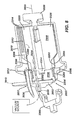
- FIG. 8 provides a cross-sectional illustration of components of the tissue storage assembly of FIG. 6 .
- FIG. 9 is a schematic illustration of a manifold having radially extending fins and vacuum ports for conveying vacuum between adjacent fins.
- FIG. 10 illustrates an alternative embodiment of a tissue holder
- FIG. 11 illustrates another alternative embodiment of a tissue holder.
- FIG. 11A illustrates a tissue holder of FIG. 11 in a relatively flat configuration.
- FIG. 12 illustrates a tissue holder for holding tissue samples in an end-to-end configuration.
- FIG. 12A is a cross-sectional schematic illustration taken along lines 12 A- 12 A in FIG. 12 .
- FIG. 12B is a sectional view taken along a portion of the length of the tissue holder shown in FIG. 12 .
- FIG. 13 is a schematic illustration of the distal portion of an exemplary cannula.
- FIG. 14 is a schematic illustration of the vacuum level provided in a vacuum lumen as a cutter is advanced and retracted in a cutter lumen relative to a tissue receiving aperture.
- FIG. 15 is a schematic illustration of a pneumatic control configuration that may be used with a biopsy device.
- FIG. 16 illustrates multiple control states that can be employed in controlling a biopsy device.
- FIG. 1 shows a biopsy device 10 according to one embodiment of the present invention.
- the biopsy device 10 of this example comprises a handpiece identified generally as numeral 30 .
- Handpiece 30 can be held comfortably in a single hand, and can be manipulated with a single hand.
- Biopsy device 10 can include a tissue piercing portion, such as cannula 100 , extending distally from the handpiece 30 .
- the cannula 100 can include a distal tissue piercing tip 110 and a transverse tissue receiving aperture 114 spaced proximally of the tip 110 .
- the cannula 100 can be inserted into a tissue mass to be sampled. Tissue drawn into the aperture 114 can then be severed by the distal end 122 of a tubular cutter 120 ( FIG. 2 ) translating within the cannula 100 .
- the biopsy device 10 of the present example also includes a tissue storage assembly 2000 , which can be disposed at a proximal end of the handpiece 30 , proximal to the cutter 120 .
- the tissue storage assembly 2000 can include a generally transparent cover 2010 , which can be releasably joined to biopsy device 10 , such as at the proximal end of the handpiece 30 .
- the cover 2010 may be substantially translucent, opaque, combinations of transparent and opaque, etc., or have any other suitable properties.
- the cover 2010 can be releasably joined to the proximal end of the handpiece 30 by any suitable attachment mechanism or feature, including but not limited to by snap fit, bayonet fitting, threaded style fitting, etc.
- the cover 2010 has a flange 2012 that provides a releasable snap fit engagement with proximal end of handpiece 30 .
- the tissue storage assembly 2000 shown also includes at least one tissue holder 2200 disposed within a removable cover 2010 , the holder 2200 being releasably carried on a rotatable member.
- the rotatable member is in the form of a manifold 2300 ( FIG. 7 ), though other structures or configurations may be used.
- the manifold 2300 can be disposed at least partially within the cover 2010 .
- the tissue sample holder 2200 can be shaped or otherwise configured to hold a plurality of tissue samples (designated generally by numeral 42 ), such as those severed by the cutter 120 , in a sequenced, spaced apart order on the holder 2200 .
- the rotatable manifold 2300 and the tissue holder 2200 of the present example can be rotated automatically, such as by being rotationally indexed through a predetermined angular increment each time a tissue sample 42 is severed, as described below.
- a manual rotation knob 2020 can be provided to permit manual rotation of the manifold 2300 and the tissue holder 2200 , in case the user desires to “override” the automatic indexing.
- the tissue storage assembly 2000 can also include an actuator, such as a control lever 2040 for selecting the direction of rotational indexing (clockwise or counterclockwise) of the rotatable manifold 2300 and the tissue holder 2200 within the transparent cover 2010 .
- knob 2020 and lever 2040 are merely optional, and may be modified, substituted, supplemented, or omitted as desired.
- FIGS. 2-5 A sequence of operation of a biopsy device employing a tissue storage assembly 2000 according to one embodiment of the present invention is shown in FIGS. 2-5 .
- the tissue storage assembly 2000 is shown with the cover 2010 removed.
- FIGS. 6, 7, and 8 illustrate the tissue storage assembly 2000 of the present example in more detail.
- FIG. 2 the internal components of an exemplary biopsy device 10 suitable for use in a stereotactic application are shown.
- the cannula 100 is shown in a “fired” position, corresponding to the cannula 100 having been directed into tissue by a firing assembly 150 .
- the firing assembly 150 of the present example includes a firing fork 152 , which can be cocked (such as by a manual cocking apparatus or by a cocking motor 156 ), with the energy for firing being stored in a firing spring 158 .
- firing assembly 150 may have any other suitable configuration or may be omitted altogether.
- a tubular cutter 120 is disposed in a cutter lumen 104 of cannula 100 in the present example.
- the cutter 120 is shown in a retracted position, with a distal cutting end 122 (shown in phantom) of the cutter 120 positioned just proximal of the tissue receiving aperture 114 in cannula 100 .
- the cutter 120 retracts to the position shown in FIG. 2 in an exemplary mode of operation.
- the cannula 100 can also include a vacuum lumen 108 disposed beneath cutter lumen 104 .
- Vacuum lumen 108 of the present example communicates vacuum to cutter lumen 104 just below port aperture 114 through a plurality of passageways 107 ( FIG. 13 ) to assist in drawing tissue into port 114 when the cannula 100 is disposed in tissue and the cutter 120 is in the retracted position shown in FIG. 2 .
- the cutter 120 extends from the distal cutting end 122 to a cutter proximal end 124 .
- the cutter 120 passes through the cutter lumen 104 of cannula 100 , a vacuum manifold 300 , saline/vacuum valve assembly 4080 , and a cutter gear 410 .
- the proximal end 124 of the cutter 120 communicates with a distal end of a tissue sample transfer tube 2030 .
- Sample transfer tube 2030 can be a flexible tube joined to the proximal end 124 of cutter 120 by a slip joint 2028 , or other suitable connection for permitting relative axial motion and rotation of the cutter end 124 relative to the tube 2030 .
- the proximal end of the sample transfer tube 2030 communicates with a tissue sample port 2057 of proximal cover 2050 of the tissue storage assembly 2000 .
- the proximal cover 2050 encloses the proximal end of the tissue storage assembly 2000 .
- the proximal cover 2050 and the generally transparent cover 2010 together, provide a tissue storage chamber within which the manifold 2300 and the tissue holder 2200 are at least partially disposed.
- the port 2057 and a vacuum port 2060 for communicating vacuum to the manifold 2300 can be formed integral with the cover 2050 . It will be appreciated in view of the teachings herein, however, that sample transfer tube 2030 may be varied, substituted, supplemented, or omitted as desired; and that a variety of other components or features may be used to provide fluid communication between cutter 120 and tissue storage assembly 2000 .
- Tissue samples 42 cut by cutter 120 can be transported through cutter 120 , then through sample transfer tube 2030 , to be deposited into the tissue storage chamber of the tissue storage assembly 2000 .
- Vacuum can be provided from a vacuum source to the tissue storage assembly 2000 through vacuum port 2060 in cover 2050 or otherwise.
- the tissue samples 42 entering the tissue storage chamber through the port 2057 in cover 2050 are deposited on the tissue holder 2200 in the present example.
- the proximal cover 2050 can also include an access opening 2052 , as shown in FIG. 6 .
- Teeth 2354 of a manifold rotation gear 2350 can be engaged by an indexing pawl 2362 through opening 2052 .
- Manifold rotation gear 2350 can be coupled to the manifold 2300 by a spline connection or other suitable connection, such that rotation of gear 2350 causes manifold 2300 to rotate.
- the proximal cover 2050 includes a flange 2056 that can be captured between mating halves (not shown) of the body of the biopsy device 10 , such that the cover 2050 can be rotated about a longitudinal axis 2055 ( FIG. 6 ) of the tissue storage assembly 2000 .
- Lever 2040 can be employed to rotate the cover 2050 (and access opening 2052 ) circumferentially from a first o'clock position to a second o'clock position.
- lever 2040 is in the position shown in the Figures (e.g., FIGS. 1 and 6 )
- pawl 2362 engages the teeth 2354 through opening 2052 .
- Pawl 2362 provides indexed rotation of the manifold 2300 in one direction about axis 2055
- pawl 2364 provides indexed rotation of the manifold 2300 in the opposite direction about axis 2055 .
- the entry point of the tissue samples 42 into the tissue storage assembly 2000 is also changed in the present example.
- the position of port 2057 moves circumferentially when the position of lever 2040 is changed, with the transfer tube 2030 accommodating this motion.
- the entry point of the tissue samples is offset from a twelve o'clock position (straight up) in the embodiment shown.
- the lever 2040 can be employed to select the tissue entry point to be at either about a 2 o'clock or about a 10 o'clock position, so that the entry of the samples into the assembly 2000 can be seen through clear cover 2010 of the tissue storage assembly 2000 by an operator using the biopsy device 10 in a stereotactic environment, where the top of the biopsy device 10 may be positioned close to the surface of the underside of the stereotactic table.
- any other suitable structure(s) or device(s) may be used in addition to or in lieu of lever 2040 to reposition port 2057 .
- one or more motors or transmissions may be used to selectively reposition port 2057 .
- the circumferential or angular position port 2057 may be substantially fixed (e.g., at 12 o'clock, etc.).
- pawls 2362 , 2364 may be varied, substituted, supplemented, or omitted as desired.
- a cutter lead screw 510 is supported on the biopsy device 10 , to be rotated by a cutter motor 500 .
- Rotation of screw 510 causes cutter carriage nut 520 to advance or retract on screw 510 , depending on the direction of rotation of the screw 510 .
- Nut 520 can be attached to, or integral with, a cutter carriage 530 .
- Cutter 120 is rotatably supported on the carriage 530 in this example, so that cutter 120 can be rotated by gear 410 as the cutter carriage translates the cutter 120 .
- Movement of nut 520 on screw 510 causes carriage 530 and cutter 120 to move axially, either proximally (retract) or distally (advance), depending on the direction of rotation of motor 500 and screw 510 .
- the cutter 120 is rotated about its axis by cutter rotation gear 410 as gear 410 engages drive gear 512 .
- Rotation of drive gear 512 can also be powered by motor 500 .
- Cutter 120 may thus be rotated and translated concomitantly by activation of motor 500 .
- the cutter carriage nut 520 is shown in its proximal (retracted) position corresponding to distal end 122 of cutter 120 being positioned just proximal of the aperture 114 .
- pawl 2362 is pivotably mounted on pawl sled 2360 .
- the pawl sled 2360 is shown in its proximal most position.
- the sled 2360 has been pushed proximally by a tab extension 522 on the carriage nut 520 .
- Proximal movement of sled 2360 compresses sled spring 2361 .
- the compressed sled spring 2361 can be employed to urge sled 2360 distally (advance sled) when nut 520 and tab extension 522 advance distally on the lead screw 510 .
- spring 2361 may be omitted, varied, etc., if desired.
- a vacuum control module 5000 ( FIG. 15 ) can direct vacuum to the vacuum lumen 108 to draw tissue into the aperture 114 .
- the cutter 120 has been advanced to its distal most position to sever a tissue sample 42 , and the cutter 120 is shown to extend across and closes the aperture 114 in cannula 100 .
- the cutter 120 advances from the position of FIG. 2 to the position shown in FIG. 3 , the cutter 120 also rotates under the action of cutter rotation gear 410 , which is rotated by drive gear 512 .
- carriage 530 and cutter 120 have been advanced by translation of nut 520 on screw 510 .
- a severed tissue sample 42 is shown exiting the sample transfer tube 2030 and being deposited on the tissue holder 2200 .
- the vacuum in vacuum lumen 108 is turned off and a vacuum control valve is employed to provide atmospheric pressure to the vacuum lumen 108 , while cutter 120 is still in its distal most position covering the tissue receiving aperture 114 .
- a supply of saline can be provided.
- Valving can be employed to direct the saline to flow distally through the vacuum lumen 108 of cannula 100 to one or more holes or passageways 107 providing fluid communication between cutter lumen 104 and vacuum lumen 108 at the distal end of cannula 100 .
- the saline flow and/or the atmospheric pressure provide a proximally directed force on the tissue sample severed by cutter 120 , which provides a proximally directed “push” on the severed tissue sample disposed at the distal portion of cutter 120 .
- a tissue storage vacuum source can be provided that communicates a vacuum to the vacuum port 2060 .
- the vacuum provided at port 2060 is communicated through tissue storage assembly 2000 to the cutter 120 via sample transfer tube 2030 .
- the vacuum provided at port 2060 provides a proximally directed “pull” on the severed tissue sample in the cutter 120 .
- the combined proximally directed “push” and “pull” on the severed tissue sample serve to convey the tissue sample 42 through the cutter 120 (from the cutter distal end 122 to the cutter proximal end 124 ), through the sample transfer tube 2030 , (which can extend through an opening in cover 2050 as shown in FIG.
- tissue sample 42 is shown being deposited on the tissue holder 2200 in FIG. 4 .
- the vacuum provided to vacuum port 2060 can be kept “on” throughout the sample cutting cycle, so that vacuum pressure is present inside the hollow cutter 120 at all times. Alternatively, the vacuum provided to vacuum port 2060 can be cycled on and off according to a predetermined schedule.
- tissue sample 42 may be conveyed from the cutter distal end 122 to the tissue holder 2200 , including structures and devices that may be used, as well as fluid communication parameters, will be apparent to those of ordinary skill in the art in view of the teachings herein.
- the manifold and 2300 and the tissue holder 2200 can be rotationally indexed (as indicated by arrow labeled R) during retraction of the cutter 120 .
- Motor 500 powers rotation of lead screw 510 to translate nut 520 , cutter carriage 530 , and cutter 120 proximally, thereby opening tissue aperture 114 in cannula 100 .
- the tab extension 522 pushes the pawl sled 2360 in a proximal direction, causing pawl 2362 to engage teeth 2354 and push “upward” on teeth 2354 , causing manifold gear 2350 (and so manifold 2300 ) to rotate in the direction “R” shown in FIG. 5 .
- the tissue holder 2200 rotates with the manifold 2300 , and is positioned to have an empty recess or compartment aligned with port 2057 and sample transfer tube 2030 .
- the manifold 2300 and tissue holder 2200 can be rotated based on a rotational position of the tissue receiving aperture 114 .
- the cannula 100 may be rotatable with respect to the biopsy device to position the aperture 114 at a desired o'clock position, such as with a thumbwheel.
- U.S. Pat. No. 6,602,203 incorporated herein by reference, discloses a thumbwheel for rotating a tissue receiving aperture.
- the manifold 2300 and tissue holder 2200 can configured to be rotated concomitantly with rotation of the aperture 114 , so that each tissue holding recess or compartment on the tissue holder 2200 corresponds to a specific o'clock position of the aperture 114 during tissue sampling.
- motor 500 or a separate motor can be provided to rotate the tissue holder 2200 and manifold 2300 .
- manifold 2300 may be rotated using any other suitable components, features, devices, or techniques.
- Tissue holder 2200 may additionally or alternatively rotate a predetermined amount upon translation of the cutter 120 , such as when the cutter 120 is advanced or retracted, so that with each cutter 120 stroke, the rotatable manifold 2300 repositions the tissue holder(s) 2200 supported on the manifold 2300 , such that the tissue holders 2200 are “clocked” to receive the tissue sample 42 severed during that cutter 120 stroke.
- a switch or lever e.g., lever 2040
- the entry point of the tissue sample into the tissue storage assembly can also be changed.
- the entry point of the tissue samples may be offset from a twelve o'clock position (straight up).
- the lever can be employed to select the tissue entry point to be at either about a 2 o'clock or about a 10 o'clock position, so that the entry of the samples into the assembly can be seen through a clear cover 2010 of the tissue storage assembly 2000 by an operator using the biopsy device 10 in a stereotactic environment where the biopsy device 10 may be positioned close to the surface of the underside of the stereotactic table or elsewhere.
- FIG. 6 provides an enlarged illustration of the tissue storage assembly 2000 of the present example.
- FIG. 7 provides an exploded view of components of the tissue storage assembly 2000 .
- FIG. 8 provides a cross-sectional illustration of components of the tissue storage assembly 2000 .
- FIG. 9 is a schematic illustration of a manifold 2300 having radially extending fins 2320 and vacuum ports 2324 for conveying vacuum between adjacent fins.
- the tissue sample assembly 2000 of the present example can comprise a plurality of tissue holders 2200 .
- the tissue sample assembly comprises three sample holders designated 2200 A, 2200 B, and 2200 C.
- the tissue holders 2200 A-C are releasably carried by the manifold 2300 .
- Each tissue holder 2200 can be removed from the biopsy device 10 by removing the cover 2010 and lifting or sliding the holder 2200 off of the manifold 2300 with the tissue samples 42 held in place on the tissue holder 2200 .
- each of the tissue holders 2200 A-C can extend about one hundred and twenty degrees around the circumference of the manifold 2300 .
- tissue holders 2200 AA-C may extend to any other suitable range (e.g., approximately 90 degrees, approximately 180 degrees, approximately 360 degrees, etc.).
- Each of the tissue holders 2200 A-C of the present example is shaped or otherwise formed to receive and hold a plurality of tissue samples 42 in spaced apart, sequenced order.
- each tissue holder 2200 A-C is in the form of a flexible tissue sample strip, and each tissue sample strip includes a plurality of recesses 2204 , each recess 2204 for receiving a respective tissue sample 42 .
- the manifold 2300 can include a plurality of radially extending projections, such as radially extending fins 2320 .
- the tissue holders 2200 A-C can be shaped or otherwise formed to engage the fins 2320 , such that the fins 2320 prevent circumferential motion of the holders 2200 A-C relative to the manifold 2300 , and such that the fins 2320 maintain the three tissue holders 2200 A-C in position on the manifold 2300 .
- each recess 2204 can be positioned between a pair of adjacent fins 2320 of the manifold 2300 .
- any suitable structure or feature other than fins 2320 may be provided by manifold 2300 .
- the tissue sample holders 2200 A-C can be formed from thin polymeric sheet stock or using other materials, structures, and techniques. If desired, the tissue sample holders 2200 A-C can be formed of a material that is generally radiotransparent (generally transparent to X-rays). In one embodiment, the sample holders 2200 A-C can be formed of polypropylene having a thickness of about 0.015 inch or any other suitable thickness. The sample holders 2200 A-C can have a radially inward facing surface 2203 and a radially outward facing surface 2205 ( FIG. 8 ).
- the sample holders 2200 A-C can be formed (such as by molding, vacuum forming, or pressing, etc.) to have tissue receiving recesses 2204 on the radially outward facing surface 2205 of the strips, each recess 2204 having a floor 2205 , radially outward extending sidewalls 2206 , and a proximal back wall 2208 .
- Each recess 2204 can be positioned between a pair of adjacent manifold fins 2320 when the sample holder 2200 A-C is seated on the manifold 2300 .
- Each sample holder 2200 A-C can also include a distally extending lip 2260 .
- sample holders 2200 A-C can be formed to receive tissue samples on a radially inward facing surface 2203 of the sample holders 2200 A-C or in some other suitable fashion.
- Vacuum openings 2212 , 2214 can be provided in the sample holders 2200 A-C to communicate vacuum from the manifold 2300 through the sample holder 2200 A-C, to convey tissue samples 42 from sample transfer tube 2030 to recesses 2204 .
- vacuum openings 2214 can extend through the sidewalls 2206
- vacuum openings 2212 can extend through the floor 2205 .
- any other structures in any suitable location may be used to permit fluid communication through sample holders 2200 A-C.
- the manifold 2300 can include fins 2320 extending from a generally disc shaped distal end plate 2310 .
- the distal face of the end plate 2310 includes a spline feature 2314 for mating with a complementary recess (not shown) in the manifold gear 2350 .
- the end plate 2310 also includes a plurality of vacuum ports 2324 extending through the end plate 2310 , each port 2324 positioned to direct vacuum between an adjacent pair of fins 2320 .
- Vacuum provided from a vacuum source (e.g., from vacuum pump 4010 , described below) and communicated to vacuum port 2060 in proximal cover 2050 is directed through cover 2050 to one of a plurality of passageways 2352 extending through the gear 2350 .
- Each passageway 2352 extending through the manifold gear 2350 can be aligned with an associated vacuum port 2324 in the manifold end plate 2310 when the spline feature 2314 mates with the manifold gear 2350 .
- vacuum provided at port 2060 is directed through cover 2050 to a passageway in the gear 2350 , and then through a vacuum port 2324 in manifold 2300 , to be directed between a pair of adjacent fins 2320 .
- the direction of airflow provided by the sample storage vacuum supply is illustrated by arrows in FIG. 8 .
- the tissue holder 2200 comprises a plurality of sample holders 2200 A-C.
- the tissue holder 2200 can comprise a single piece, such as in the form of a continuous ring extending three hundred and sixty degrees around the manifold 2300 , or as a single strip extending substantially three hundred sixty degrees around the manifold.
- any other suitable structures, features, or devices may be used to hold tissue samples 42 .
- FIG. 10 illustrates an alternative embodiment of a tissue sample holder 2200 .
- a sample holder 2200 comprises a single strip comprising four segments 2201 A-D, with adjacent pairs of the segments 2201 A-D being joined together at a flexible hinges 2203 .
- Each segment 2201 A-D can have a generally arcuate shape encompassing about 90 degrees, with a generally convex outer surface having a plurality of recesses, each recess for holding a tissue sample.
- the holder 2200 of this example which can be radiotransparent or have other properties, can be removed from the tissue storage assembly 2000 with the tissue samples 42 held in spaced apart, sequenced order on the tissue holder 2200 .
- the samples 42 can be tested and/or prepared for testing without removing the samples 42 from the holder 2200 , and without disturbing the order of the samples 42 and/or without touching the individual samples 42 , such as by placing the samples 42 and holder 2200 in any suitable test equipment or in a suitable test preparation fluid.
- tissue samples 42 can be subject to any other suitable processing, either while still on tissue holder 2200 or otherwise.
- FIGS. 11 and 11A illustrate another embodiment of a tissue sample holder 2200 .
- the sample holder 2200 comprises a plurality of arms 2272 extending radially from a hub 2270 .
- the hub 2270 can have a generally cylindrical shape and can be sized to fit over an end of a manifold 2300 .
- the arms 2272 can be sized and spaced to fit between adjacent fins 2320 of the manifold 2300 .
- the arms 2272 can each include a tissue receiving compartment 2274 , which can be integrally formed in the arm 2272 itself, or alternatively, be a separate piece joined to the arm 2272 .
- Tissue receiving compartments 2274 provide a cup-like or recessed configuration in the present example, though other configurations may be provided.
- Each arm 2272 can include one or more vacuum openings for communicating vacuum from the manifold 2300 to the tissue receiving compartment 2274 .
- Each arm 2272 can be joined to the hub at a hinge 2275 .
- Each hinge 2275 can be a flexible “living” hinge, formed for instance, from a thin flexible strip of the material from which the arms 2272 are formed. Alternatively, other configurations may be used.
- the flexible hinge 2275 of the present example permits the arms 2272 to folded radially inward to extend generally parallel to the longitudinal axis 2271 of the hub 2270 when the holder 2200 is disposed in the tissue storage assembly 2000 .
- the flexible hinge 2275 of the present example permits the arms 2272 to folded radially outward to a flatter configuration, such as is shown in FIG. 11A .
- the tissue holder 2200 can include indicia (e.g. letters, numbers, symbols, etc.) that are visible and/or radiopaque.
- the indicia can be used to identify each individual tissue holding recess or compartment 2274 on the tissue holder 2200 .
- Each recess or compartment 2274 can have a unique number or symbol associated with it, where the number or symbol is formed or printed on the holder 2200 to be visible to the naked eye and/or radiopaque. Accordingly, when the tissue holder 2200 is withdrawn from the biopsy device 10 , the individual tissue samples 42 can be uniquely identified on the holder 2200 both visibly and/or under x-ray.
- the biopsy device 10 can include a display (not shown) for indicating the number of tissue samples 42 cut as the biopsy device 10 is operated.
- the biopsy device 10 or the control unit 5000 can include a display, such as an LED display, that indicates the number of tissue samples 42 that have been severed and stored.
- the LED display can include a diagrammatic display that indicates the location from which each sample 42 is taken relative to a reference. For instance, the display can indicate the “o'clock” position at which each sample 42 is taken relative to an initial 12 o'clock (straight up) position of the tissue aperture 114 .
- the LED display can indicate a position for each compartment or recess 2274 on the tissue holder 2200 , with the LED display indicating if a tissue sample 42 has been deposited in a particular compartment or recess 2274 , or at a particular location around the circumference of the tissue holder 2200 .
- a display may be incorporated with biopsy device 10 in any other suitable way and location, and may display any desired information.
- FIG. 12 illustrates an alternative tissue storage device 2700 that can be used to hold tissue samples 42 in an end-to-end configuration.
- FIG. 12A is a cross-sectional view taken along lines 12 A- 12 A.
- FIG. 12B is a sectional view taken along a length of a portion of the storage device 2700 .
- the storage device 2700 of this example includes a flexible, coiled tissue sample holder 2710 , which can be formed of thin-walled, flexible tubing, such as an extruded tubing.
- the tissue sample holder 2710 includes three lumens 2712 , 2714 , 2716 extending alongside each other along the length of the coiled tissue sample holder 2710 .
- the sample holder 2710 of this example includes a tissue sample lumen 2712 for receiving tissue samples 42 in end-to-end sequence, a vacuum supply lumen 2714 , and a vacuum control lumen 2716 positioned between and extending alongside of lumen 2712 and lumen 2714 .
- a flexible, elongated control member 2718 is positioned in control lumen 2716 . When the elongated control member 2718 is fully inserted in the control lumen 2716 , the control member 2718 serves to block a series of cross flow ports 2719 , which are disposed at spaced intervals along the length of the vacuum control lumen 2716 .
- the cross flow ports 2719 can be spaced apart along the length of the vacuum control lumen 2716 a distance generally equal to or slightly larger than the maximum length of a tissue sample 42 severed by the cutter 120 of the biopsy device 10 .
- Control member 2718 can be withdrawn from lumen 2716 in the direction shown, in incremental steps, to permit vacuum in vacuum supply lumen 2714 to be communicated to sample lumen 2712 .
- a pair of cross flow ports 2719 in vacuum control lumen 2716 are uncovered to provide vacuum in sample lumen 2712 .
- a vacuum may be selectively communicated to a sample lumen 2712 using any other suitable structures, features, devices, or techniques.
- tissue sample lumen 2712 can be connected directly or indirectly to the sample transfer tube 2030 .
- Lumen 2714 can be connected to a source of vacuum (e.g., vacuum control module 5000 ).
- the control member 2718 can be withdrawn manually, or alternatively, can be automatically withdrawn by a winding mechanism (not shown) associated with the biopsy device 10 .
- FIG. 13 provides a schematic illustration of the distal portion of cannula 100
- FIG. 14 provides a schematic illustration of the vacuum level that can be provided in vacuum lumen 108 as cutter 120 is advanced and retracted in cutter lumen 104 relative to tissue receiving aperture 114
- FIG. 13 illustrates passageways that can be provided in the internal structure of cannula 100 to provide flow communication between vacuum lumen 108 and cutter lumen 104 .
- Passageways 107 are disposed generally beneath aperture 114
- passageway 109 is disposed distal of aperture 114 .
- FIG. 15 is a schematic illustration of a pneumatic configuration that can be used with the biopsy device 10 of the present example.
- the pneumatic system can include a vacuum pump 4010 , a regulator 4020 , a vacuum canister/reservoir 4030 , a master control valve 4060 , and a saline/vacuum valve 4080 .
- the vacuum provided by the vacuum pump 4010 can be directed through vacuum line 4012 , through tissue storage assembly 2000 , to cutter 120 and cutter lumen 104 without valving, so that the vacuum provided to the interior of cutter 120 and to cutter lumen 104 of cannula 100 is always “on” when vacuum pump 4010 is operating.
- one or more valves or other features or mechanisms may be provided along such a fluid path.
- the pneumatic circuit for vacuum lumen 108 includes two valves 4060 , 4080 .
- Valve 4080 can comprise a 3-port/2-position valve, with two input ports. One input port can be connected to vacuum line 4012 , and the other input port can be connect to a source of saline 4016 (or alternatively vented to atmospheric pressure through filter 4018 ).
- the output port of valve 4080 communicates with an inlet port of master valve 4060 .
- the position of the valve 4080 is configured to correspond to the position of the cutter 120 .
- the valve 4080 communicates vacuum to the master control valve 4060 .
- the valve 4080 communicates saline to the master control valve 4060 .
- valve 4080 communicates atmospheric air via filter 4018 to the master control valve 4060 .
- the valve 4080 can be actuated in any suitable manner, including with a solenoid, a motor, by a mechanical link to the cutter 120 , or otherwise.
- the valve 4080 can be spring loaded in one position, and movement of the cutter 120 (such as movement of the cutter 120 to the distal position) can be employed to change the valve 4080 position.
- the master control valve 4060 can comprise a 3-port/3-position valve. One input port can be connected to the output port of the valve 4080 . The second input port can be vented to filtered atmospheric air. The output port of the valve 4060 can be connected to the proximal end of vacuum lumen 108 of cannula 100 .
- the position of valve 4060 can be controlled by the operator of the biopsy device 10 using one or more user control interfaces, such as the control buttons listed in FIG. 16 .
- the control buttons (not shown on device 10 ), can be located at any convenient position on the body of the biopsy device 10 , including for instance on handpiece 30 , or elsewhere (e.g., on vacuum control module 5000 ).
- the valve 4060 can be actuated by a solenoid, motor, via a link to the cutter 120 , or otherwise.
- pneumatic circuit shown in FIG. 15 is merely illustrative, and any other suitable circuit, including different components, arrangements of components, and operation of components, may be used.
- FIG. 16 illustrates multiple control states that can be employed in controlling the biopsy device 10 .
- the “Ready State” of biopsy device 10 corresponds to the cutter 120 being advanced to its distal most position and tissue aperture 114 being closed.
- the valve 4080 communicates saline to the master control valve 4060 and the master control valve is positioned to seal off (close) its other ports, including the output port communicating with vacuum lumen 108 .
- the port to the lateral lumen 108 By closing the port to the lateral lumen 108 while in the Ready State, airflow through the device may be minimized, which may allow the pump 4010 to more easily maintain the desired vacuum level at the vacuum canister 4030 .
- the cutter motor is activated to cause the cutter 120 to retract proximally.
- the valve 4080 changes position to communicate vacuum to the master control valve 4060 .
- the master control valve changes position to communicate a vacuum to the vacuum lumen 108 .
- vacuum from vacuum pump 4010 is applied to the cutter 120 (such as via the tissue storage assembly 2000 ) and cutter lumen 104 (via the cutter 120 ), as well as to the vacuum lumen 108 (via the valves 4080 and 4060 ). Vacuum applied to both cutter lumen 104 and vacuum lumen 108 assists in prolapsing tissue into aperture 114 of cannula 100 .
- the cutter 120 After maintaining this vacuum state for a second or more to ensure tissue has prolapsed into aperture 114 , the cutter 120 is advanced distally (and simultaneously rotated) to close the aperture 114 and sever a tissue sample 42 in the distal portion of the hollow cutter 120 .
- the cutter 120 can contact or otherwise actuate the valve 4080 to change the valve position to communicate saline to the master control valve 4060 .
- a microprocessor can be employed to change the master control valve 4060 position to communicate filtered atmospheric air to vacuum lumen 108 , which in turn is communicated via passageways 107 , 109 to the distal face of the severed tissue sample 42 positioned in the distal portion of hollow cutter 120 .
- tissue sample 42 The atmospheric air on the distal face of the tissue sample provides a proximal pushing force on the tissue sample 42 , while the vacuum provided in cutter 120 (via the tissue storage assembly 2000 ) provides a proximally directed pulling force on the severed tissue sample 42 .
- the resulting proximally directed force on the tissue sample 42 conveys the tissue sample 42 through the hollow cutter 120 into tissue storage assembly 2000 .
- any other suitable structures or techniques may be used to capture a tissue sample 42 and communicate it to a tissue storage assembly 2000 .
- the microprocessor can be employed to change the position of master control valve 4060 to first communicate saline to vacuum lumen 108 for a predetermined period of time, and then change the valve's position to communicate atmospheric air to the lumen 108 .
- a fixed volume of saline can be delivered via passageways 107 , 109 to the distal end of hollow cutter 120 , thereby assisting in moving the severed tissue sample proximally through hollow cutter 120 to tissue storage assembly 2000 .
- the control system can be programmed to return to the Ready State after a predetermined period of time (e.g., one or more seconds).
- the biopsy device operator can depress the “Clear Probe” button 172 while in the Ready State (e.g., after having operated the “Sample” button 170 to sever tissue) in order to direct a microprocessor control to cause the cutter 120 to reciprocate slightly to open and close aperture 114 a fraction of an inch (e.g. 0.2 inches), or to any suitable degree.
- This reciprocation of cutter 120 can be effective to dislodge the tissue sample 42 or otherwise free the sample 42 so that the sample 42 can travel freely through hollow cutter 120 .
- the vacuum control valve 4060 can be repositioned to communicate saline to the vacuum lumen 108 and through passageways 107 , 109 to provide a pushing force on the distal face of the tissue sample 42 .
- the microprocessor can return the pneumatic system to the Ready State.
- the operator can depress and release the “Aspirate/Insert” button 174 when the device is in the Ready State to insert medication or a tissue marker into the tissue being sampled or into the site from which a tissue sample has been or will be taken.
- the button 174 is depressed in this example, the cutter 120 moves proximally to open aperture 114 .
- the position of the master control valve 4060 is changed to communicate atmospheric air to the vacuum lumen 108 . Depressing the “Aspirate/Insert” button 174 also turns off the vacuum (such as by either turning off the pump 4010 or opening regulator 4020 to vent pump 4010 outlet to atmosphere, etc.).
- the tissue marker applier (or medication) can be fed into the proximal end of the cannula 100 through hollow cutter 120 , such as via the tissue storage assembly 2000 or otherwise, with the marker (or medication) being then deployed through the open aperture 114 in cannula 100 .
- the user may press any button, which may advance the cutter 120 to return to the Ready State with the master control valve 4060 positioned up.
- the operator can depress and hold the “Aspirate/Insert” button 174 to aspirate fluid in the vicinity of aperture 114 .
- the cutter 120 moves proximally to open aperture 114 .
- the valve 4080 communicates vacuum to the master control valve 4060 , and the master control valve 4060 is positioned to communicate vacuum to the vacuum lumen 108 .
- vacuum is applied to both the lumen 108 and the cutter lumen 104 (because vacuum is provided continuously through cutter 120 to lumen 104 while the pump 4010 operates in this example).
- the vacuum provided to lumen 104 and lumen 108 aspirates any liquid near the aperture 114 .
- the pneumatic system is controlled to return the Ready State.
- the cutter 120 is advanced to close aperture 114 .
- the master control valve 4060 is positioned to communicate filtered atmospheric air to the vacuum lumen 108 . Once the aperture 114 is closed, the master control valve 4060 is positioned to close all its ports to attain the Ready State.
- the foregoing operational sequence is merely illustrative, and any other suitable operational sequences may be used in addition to or in lieu of those explicitly described herein.
- the length of the vacuum line 4012 from the control module 5000 housing the vacuum pump 4010 to the biopsy device 10 can be relatively long (as much as 20 feet or more in some cases) in order to accommodate movement of the biopsy device 10 in the operating room, or due to limitations of the position of the control module 5000 in magnetic resonance imaging environments.
- vacuum line 4012 may be of any desired length.
- the vacuum line 4012 can account for a considerable portion of the flow volume that needs to be supplied or maintained by the vacuum pump 4010 and vacuum canister 4030 when the tissue aperture 114 is open.
- Placing the saline vacuum valve 4080 and the master control valve 4080 at the distal end of the vacuum line 4012 (the end associated with the biopsy device 10 ) instead of in the biopsy vacuum control unit 5000 may mean that a smaller vacuum pump 4010 and a smaller vacuum canister 4030 can be used.
- valving may be placed in the control unit that includes the vacuum pump, and the control unit is may be mounted on wheels due to its weight and size.
- FIG. 16 the valves 4060 , 4080 are shown disposed in the biopsy device 10 .
- the valves 4060 , 4080 can be disposed in a disposable probe portion that includes the cannula 100 and cutter 120 (e.g.
- a valve placement may allow a relatively low weight diaphragm vacuum pump 4010 having a flow rate of about 18 liters per minute to be used, as compared to a conventional pump and valve arrangement requiring more than 80 liters per minute.
- any desired vacuum pump having any desired properties may be used.
- the vacuum canister 4030 can be relatively small, with a volume of less than about 300 cubic centimeters, as compared to a conventional vacuum canister having a volume storage capacity of 1200 cc's or more.
- a relatively lightweight, hand-portable vacuum control module 5000 can be employed.
- the vacuum control module 5000 ( FIG. 15 ) can weigh less than 25 pounds, can be carried by one hand, and can have height, width, and length dimensions each less than about 1.5 feet.
- vacuum canister 4030 and control module 5000 may have any other suitable capacity, size, weight, or other properties.
- a foot pedal (not shown) or remote keypad (not shown) can be employed to provide control input or instructions to the biopsy device 10 directly and/or to the vacuum control module 5000 .
- the foot pedal and remote keypad can be tethered (e.g., with one or more wires extending from the food pedal/keypad to the vacuum control module 5000 , etc.).
- “wireless” communication between the foot pedal/keypad and the control module 5000 and/or the biopsy device 10 can be employed.
- wireless “Bluetooth” communication and associated hardware and software can be employed to provide wireless control signals to the vacuum control module 5000 and/or the biopsy device 10 without requiring a “line of sight” for signal transmission and reception.
- an infrared transmitter and receiver can be employed to send and receive control signals.
- Other ways in which communication may be provided between components of a biopsy system e.g., between a pedal/keypad and control module 5000 ), whether wired, wireless, or otherwise, will be apparent to those of ordinary skill in the art in view of the teachings herein.
Landscapes
- Health & Medical Sciences (AREA)
- Life Sciences & Earth Sciences (AREA)
- Medical Informatics (AREA)
- Engineering & Computer Science (AREA)
- Biomedical Technology (AREA)
- Heart & Thoracic Surgery (AREA)
- Pathology (AREA)
- Molecular Biology (AREA)
- Surgery (AREA)
- Animal Behavior & Ethology (AREA)
- General Health & Medical Sciences (AREA)
- Public Health (AREA)
- Veterinary Medicine (AREA)
- Surgical Instruments (AREA)
- Sampling And Sample Adjustment (AREA)
Abstract
A biopsy device may be used to obtain and store multiple tissue samples. The device permits the tissue samples to be stored in a sequenced fashion within a generally transparent tissue storage chamber disposed at a proximal end of the biopsy device. The tissue samples can be stored on flexible tissue sample strips arranged around the circumference of a rotating vacuum manifold disposed within the chamber.
Description
This application is a continuation of and incorporates by reference U.S. patent application Ser. No. 11/952,405, filed Dec. 7, 2007; which claims priority to and incorporates by reference U.S. provisional application Ser. No. 60/869,736, filed Dec. 13, 2006, and U.S. provisional application Ser. No. 60/874,792, filed Dec. 13, 2006.
Some embodiments of the present invention relate in general to biopsy devices, and more particularly to biopsy devices having the capability to store multiple tissue samples, such as in a spaced-apart, sequenced manner, within a portion of the biopsy device.
When a suspicious tissue mass is discovered in a patient's breast or in another area through examination, ultrasound, MRI, X-ray imaging or the like, it may be necessary to perform a biopsy procedure to remove one or more samples of that tissue in order to determine whether the mass contains cancerous cells. A biopsy may be performed using an open or percutaneous method. Medical devices for obtaining tissue samples for subsequent sampling and/or testing are known in the biopsy art. For instance, a biopsy instrument now marketed under the tradename MAMMOTOME is commercially available from Ethicon Endo-Surgery, Inc. for use in obtaining breast biopsy samples.
An open biopsy may be performed by making a large incision in the breast and removing either the entire mass, called an excisional biopsy, or a substantial portion of it, known as an incisional biopsy. An open biopsy is a surgical procedure that may be done as an outpatient procedure in a hospital or a surgical center, and may involve a high cost and a high level of trauma to the patient. Open biopsy may carry relatively higher risk of infection and bleeding than does percutaneous biopsy, and the disfigurement that may result from an open biopsy may make it difficult to read future mammograms. Further, the aesthetic considerations of the patient might make open biopsy even less appealing due to the potential risk of disfigurement. Given that some biopsies show that the suspicious tissue mass is not cancerous, the potential downsides of the open biopsy procedure might render this method inappropriate in some cases.
Percutaneous biopsy may be less invasive than open biopsy. Percutaneous biopsy may be performed using fine needle aspiration (FNA), core needle biopsy, or otherwise. In FNA, a very thin needle may be used to withdraw fluid and cells from the suspicious tissue mass. This method may be low-pain, so low-pain that local anesthetic is not necessarily always used because the application of it may be more painful than the FNA itself. However, in some FNA procedures, only a small number of cells might be obtained through the procedure, rendering it relatively less useful in some situations in analyzing the suspicious tissue and making an assessment of the progression of the cancer less simple if the sample is found to be malignant.
During some core needle biopsy procedures, a small tissue sample may be removed allowing for a pathological assessment of the tissue, including an assessment of the progression of any cancerous cells that are found.
The biopsy instrument marketed under the trade name MAMMOTOME is commercially available from ETHICON ENDO-SURGERY, INC. generally retrieves multiple core biopsy samples from one insertion into breast tissue with vacuum assistance. In particular, a cutter tube is extended into a probe to cut tissue prolapsed into a side aperture under vacuum assistance, and then the cutter tube is fully retracted between cuts to extract the sample.
With a device having a relatively long cutter travel, the rate of sample taking may be limited not only by the time required to rotate or reposition the probe but also by the time needed to translate the cutter. As an alternative to relatively “long stroke” biopsy devices, a “short stroke” biopsy device is described in the following commonly assigned patent applications: U.S. patent application Ser. No. 10/676,944, entitled “Biopsy Instrument with Internal Specimen Collection Mechanism,” filed Sep. 30, 2003 in the name of Hibner et al., published as U.S. Pub. No. 2005/0215921; and U.S. patent application Ser. No. 10/732,843, entitled “Biopsy Device with Sample Tube,” filed Dec. 10, 2003 in the name of Cicenas et al, published as U.S. Pub. No. 2004/0153003, both of which are incorporated herein by reference. The cutter can be cycled through a distance substantially equal to or slightly greater than the distance across the side aperture, reducing the sample time.
The following patent documents disclose various biopsy devices, and are incorporated herein by reference in their entirety: U.S. Pat. No. 6,273,862 issued Aug. 14, 2001; U.S. Pat. No. 6,231,522 issued May 15, 2001; U.S. Pat. No. 6,228,055 issued May 8, 2001; U.S. Pat. No. 6,120,462 issued Sep. 19, 2000; U.S. Pat. No. 6,086,544 issued Jul. 11, 2000; U.S. Pat. No. 6,077,230 issued Jun. 20, 2000; U.S. Pat. No. 6,017,316 issued Jan. 25, 2000; U.S. Pat. No. 6,007,497 issued Dec. 28, 1999; U.S. Pat. No. 5,980,469 issued Nov. 9, 1999; U.S. Pat. No. 5,964,716 issued Oct. 12, 1999; U.S. Pat. No. 5,928,164 issued Jul. 27, 1999; U.S. Pat. No. 5,775,333 issued Jul. 7, 1998; U.S. Pat. No. 5,769,086 issued Jun. 23, 1998; U.S. Pat. No. 5,649,547 issued Jul. 22, 1997; U.S. Pat. No. 5,526,822 issued Jun. 18, 1996; and US Patent Application 2003/0199753 published Oct. 23, 2003 to Hibner et al. U.S. Pat. No. 5,526,822, incorporated by reference above, discloses a tissue sample cassette, including a rotary sample cassette that is belt driven. Other tissue sample storage devices are disclosed in U.S. patent application Ser. No. 10/953,395, entitled “Biopsy Device with Sample Storage,” filed Sep. 29, 2004, published as U.S. Pub. No. 2006/0074343; and U.S. patent application Ser. No. 11/198,558 filed Aug. 8, 2005, entitled “Biopsy Device with Replaceable Probe and Incorporating Vibration Insertion Assist and Static Vacuum Source Sample Stacking Retrieval,” published as U.S. Pub. No. 2007/0032741, each of which is incorporated by reference herein.
While a variety of biopsy devices have been made and used, and a variety of tissue sample storage devices and techniques have been devised, it is believed that no one prior to the inventors has made or used a biopsy system as described in the appended claims.
While the specification concludes with claims particularly pointing out and distinctly claiming the present invention, it is believed the same will be better understood by reference to the following description, taken in conjunction with the accompanying drawings in which:
The biopsy device 10 of the present example also includes a tissue storage assembly 2000, which can be disposed at a proximal end of the handpiece 30, proximal to the cutter 120. The tissue storage assembly 2000 can include a generally transparent cover 2010, which can be releasably joined to biopsy device 10, such as at the proximal end of the handpiece 30. Of course, the cover 2010 may be substantially translucent, opaque, combinations of transparent and opaque, etc., or have any other suitable properties. The cover 2010 can be releasably joined to the proximal end of the handpiece 30 by any suitable attachment mechanism or feature, including but not limited to by snap fit, bayonet fitting, threaded style fitting, etc. In FIG. 1 , the cover 2010 has a flange 2012 that provides a releasable snap fit engagement with proximal end of handpiece 30.
The tissue storage assembly 2000 shown also includes at least one tissue holder 2200 disposed within a removable cover 2010, the holder 2200 being releasably carried on a rotatable member. In the present example, the rotatable member is in the form of a manifold 2300 (FIG. 7 ), though other structures or configurations may be used. The manifold 2300 can be disposed at least partially within the cover 2010. The tissue sample holder 2200 can be shaped or otherwise configured to hold a plurality of tissue samples (designated generally by numeral 42), such as those severed by the cutter 120, in a sequenced, spaced apart order on the holder 2200.
The rotatable manifold 2300 and the tissue holder 2200 of the present example can be rotated automatically, such as by being rotationally indexed through a predetermined angular increment each time a tissue sample 42 is severed, as described below. A manual rotation knob 2020 can be provided to permit manual rotation of the manifold 2300 and the tissue holder 2200, in case the user desires to “override” the automatic indexing. The tissue storage assembly 2000 can also include an actuator, such as a control lever 2040 for selecting the direction of rotational indexing (clockwise or counterclockwise) of the rotatable manifold 2300 and the tissue holder 2200 within the transparent cover 2010. Of course, as with other components described herein, knob 2020 and lever 2040, are merely optional, and may be modified, substituted, supplemented, or omitted as desired.
A sequence of operation of a biopsy device employing a tissue storage assembly 2000 according to one embodiment of the present invention is shown in FIGS. 2-5 . In FIGS. 2-5 , the tissue storage assembly 2000 is shown with the cover 2010 removed. FIGS. 6, 7, and 8 illustrate the tissue storage assembly 2000 of the present example in more detail.
Referring to FIG. 2 , the internal components of an exemplary biopsy device 10 suitable for use in a stereotactic application are shown. In FIG. 2 , the cannula 100 is shown in a “fired” position, corresponding to the cannula 100 having been directed into tissue by a firing assembly 150. The firing assembly 150 of the present example includes a firing fork 152, which can be cocked (such as by a manual cocking apparatus or by a cocking motor 156), with the energy for firing being stored in a firing spring 158. Alternatively, firing assembly 150 may have any other suitable configuration or may be omitted altogether.
A tubular cutter 120 is disposed in a cutter lumen 104 of cannula 100 in the present example. In FIG. 2 , the cutter 120 is shown in a retracted position, with a distal cutting end 122 (shown in phantom) of the cutter 120 positioned just proximal of the tissue receiving aperture 114 in cannula 100. After firing the cannula 100 into tissue, the cutter 120 retracts to the position shown in FIG. 2 in an exemplary mode of operation.
Referring to FIG. 2 and FIG. 2A , the cannula 100 can also include a vacuum lumen 108 disposed beneath cutter lumen 104. Vacuum lumen 108 of the present example communicates vacuum to cutter lumen 104 just below port aperture 114 through a plurality of passageways 107 (FIG. 13 ) to assist in drawing tissue into port 114 when the cannula 100 is disposed in tissue and the cutter 120 is in the retracted position shown in FIG. 2 . The cutter 120 extends from the distal cutting end 122 to a cutter proximal end 124. Intermediate the distal cutting end 122 and the proximal end 124, the cutter 120 passes through the cutter lumen 104 of cannula 100, a vacuum manifold 300, saline/vacuum valve assembly 4080, and a cutter gear 410.
In the present example, the proximal end 124 of the cutter 120 communicates with a distal end of a tissue sample transfer tube 2030. Sample transfer tube 2030 can be a flexible tube joined to the proximal end 124 of cutter 120 by a slip joint 2028, or other suitable connection for permitting relative axial motion and rotation of the cutter end 124 relative to the tube 2030. The proximal end of the sample transfer tube 2030 communicates with a tissue sample port 2057 of proximal cover 2050 of the tissue storage assembly 2000. The proximal cover 2050 encloses the proximal end of the tissue storage assembly 2000. The proximal cover 2050 and the generally transparent cover 2010, together, provide a tissue storage chamber within which the manifold 2300 and the tissue holder 2200 are at least partially disposed. The port 2057 and a vacuum port 2060 for communicating vacuum to the manifold 2300 can be formed integral with the cover 2050. It will be appreciated in view of the teachings herein, however, that sample transfer tube 2030 may be varied, substituted, supplemented, or omitted as desired; and that a variety of other components or features may be used to provide fluid communication between cutter 120 and tissue storage assembly 2000.
The proximal cover 2050 can also include an access opening 2052, as shown in FIG. 6 . Teeth 2354 of a manifold rotation gear 2350 can be engaged by an indexing pawl 2362 through opening 2052. Manifold rotation gear 2350 can be coupled to the manifold 2300 by a spline connection or other suitable connection, such that rotation of gear 2350 causes manifold 2300 to rotate.
In the present example, the proximal cover 2050 includes a flange 2056 that can be captured between mating halves (not shown) of the body of the biopsy device 10, such that the cover 2050 can be rotated about a longitudinal axis 2055 (FIG. 6 ) of the tissue storage assembly 2000. Lever 2040 can be employed to rotate the cover 2050 (and access opening 2052) circumferentially from a first o'clock position to a second o'clock position. When lever 2040 is in the position shown in the Figures (e.g., FIGS. 1 and 6 ), pawl 2362 engages the teeth 2354 through opening 2052. When lever 2040 is repositioned to the other end of the slot 62 in the outer cover of the biopsy device (FIG. 1 ), the cover 2050 and access opening 2052 are rotated so that pawl 2364 engages the teeth 2354. Pawl 2362 provides indexed rotation of the manifold 2300 in one direction about axis 2055, while pawl 2364 provides indexed rotation of the manifold 2300 in the opposite direction about axis 2055.
By changing the position of lever 2040, the entry point of the tissue samples 42 into the tissue storage assembly 2000 is also changed in the present example. The position of port 2057 moves circumferentially when the position of lever 2040 is changed, with the transfer tube 2030 accommodating this motion. The entry point of the tissue samples is offset from a twelve o'clock position (straight up) in the embodiment shown. The lever 2040 can be employed to select the tissue entry point to be at either about a 2 o'clock or about a 10 o'clock position, so that the entry of the samples into the assembly 2000 can be seen through clear cover 2010 of the tissue storage assembly 2000 by an operator using the biopsy device 10 in a stereotactic environment, where the top of the biopsy device 10 may be positioned close to the surface of the underside of the stereotactic table.
It will be appreciated that any other suitable structure(s) or device(s) may be used in addition to or in lieu of lever 2040 to reposition port 2057. For instance, one or more motors or transmissions may be used to selectively reposition port 2057. Alternatively, the circumferential or angular position port 2057 may be substantially fixed (e.g., at 12 o'clock, etc.). Similarly, pawls 2362, 2364 may be varied, substituted, supplemented, or omitted as desired.
Referring again to FIG. 2 , a cutter lead screw 510 is supported on the biopsy device 10, to be rotated by a cutter motor 500. Rotation of screw 510 causes cutter carriage nut 520 to advance or retract on screw 510, depending on the direction of rotation of the screw 510. Nut 520 can be attached to, or integral with, a cutter carriage 530. Cutter 120 is rotatably supported on the carriage 530 in this example, so that cutter 120 can be rotated by gear 410 as the cutter carriage translates the cutter 120. Movement of nut 520 on screw 510 causes carriage 530 and cutter 120 to move axially, either proximally (retract) or distally (advance), depending on the direction of rotation of motor 500 and screw 510. The cutter 120 is rotated about its axis by cutter rotation gear 410 as gear 410 engages drive gear 512. Rotation of drive gear 512 can also be powered by motor 500. Cutter 120 may thus be rotated and translated concomitantly by activation of motor 500. In FIG. 2 , the cutter carriage nut 520 is shown in its proximal (retracted) position corresponding to distal end 122 of cutter 120 being positioned just proximal of the aperture 114.
Still referring to FIG. 2 , pawl 2362 is pivotably mounted on pawl sled 2360. In FIG. 2 , the pawl sled 2360 is shown in its proximal most position. The sled 2360 has been pushed proximally by a tab extension 522 on the carriage nut 520. Proximal movement of sled 2360 compresses sled spring 2361. The compressed sled spring 2361 can be employed to urge sled 2360 distally (advance sled) when nut 520 and tab extension 522 advance distally on the lead screw 510. Of course, spring 2361 may be omitted, varied, etc., if desired.
In the position shown in FIG. 2 , the biopsy device 10 is ready to obtain a tissue sample 42. A vacuum control module 5000 (FIG. 15 ) can direct vacuum to the vacuum lumen 108 to draw tissue into the aperture 114. Referring to FIG. 3 , the cutter 120 has been advanced to its distal most position to sever a tissue sample 42, and the cutter 120 is shown to extend across and closes the aperture 114 in cannula 100. As the cutter 120 advances from the position of FIG. 2 to the position shown in FIG. 3 , the cutter 120 also rotates under the action of cutter rotation gear 410, which is rotated by drive gear 512. In FIG. 3 , carriage 530 and cutter 120 have been advanced by translation of nut 520 on screw 510. As nut 520 moves distally, tab extension 522 also moves distally, and pawl sled 2360 is pushed distally by expansion of spring 2361. The pawl 2362 is disengaged and “rides over” teeth 2354 of the manifold gear 2350 as the cutter 120 advances distally from the position shown in FIG. 2 to the position shown in FIG. 3 .
Referring to FIG. 4 , a severed tissue sample 42 is shown exiting the sample transfer tube 2030 and being deposited on the tissue holder 2200. To provide transfer of the severed tissue sample 42 from the cannula 100 to the tissue storage assembly 2000, the vacuum in vacuum lumen 108 is turned off and a vacuum control valve is employed to provide atmospheric pressure to the vacuum lumen 108, while cutter 120 is still in its distal most position covering the tissue receiving aperture 114. Additionally, or alternatively, a supply of saline can be provided. Valving can be employed to direct the saline to flow distally through the vacuum lumen 108 of cannula 100 to one or more holes or passageways 107 providing fluid communication between cutter lumen 104 and vacuum lumen 108 at the distal end of cannula 100. The saline flow and/or the atmospheric pressure provide a proximally directed force on the tissue sample severed by cutter 120, which provides a proximally directed “push” on the severed tissue sample disposed at the distal portion of cutter 120.
Additionally, a tissue storage vacuum source can be provided that communicates a vacuum to the vacuum port 2060. The vacuum provided at port 2060 is communicated through tissue storage assembly 2000 to the cutter 120 via sample transfer tube 2030. Accordingly, the vacuum provided at port 2060 provides a proximally directed “pull” on the severed tissue sample in the cutter 120. The combined proximally directed “push” and “pull” on the severed tissue sample serve to convey the tissue sample 42 through the cutter 120 (from the cutter distal end 122 to the cutter proximal end 124), through the sample transfer tube 2030, (which can extend through an opening in cover 2050 as shown in FIG. 8 ), and into the tissue storage assembly 2000, to be deposited on a portion of the tissue holder 2200 (such as a recess or compartment) aligned with the sample transfer tube 2030. Tissue sample 42 is shown being deposited on the tissue holder 2200 in FIG. 4 . The vacuum provided to vacuum port 2060 can be kept “on” throughout the sample cutting cycle, so that vacuum pressure is present inside the hollow cutter 120 at all times. Alternatively, the vacuum provided to vacuum port 2060 can be cycled on and off according to a predetermined schedule. Other ways in which a tissue sample 42 may be conveyed from the cutter distal end 122 to the tissue holder 2200, including structures and devices that may be used, as well as fluid communication parameters, will be apparent to those of ordinary skill in the art in view of the teachings herein.
Referring to FIG. 5 , the manifold and 2300 and the tissue holder 2200 can be rotationally indexed (as indicated by arrow labeled R) during retraction of the cutter 120. Motor 500 powers rotation of lead screw 510 to translate nut 520, cutter carriage 530, and cutter 120 proximally, thereby opening tissue aperture 114 in cannula 100. As nut 520 travels proximally, the tab extension 522 pushes the pawl sled 2360 in a proximal direction, causing pawl 2362 to engage teeth 2354 and push “upward” on teeth 2354, causing manifold gear 2350 (and so manifold 2300) to rotate in the direction “R” shown in FIG. 5 . The tissue holder 2200 rotates with the manifold 2300, and is positioned to have an empty recess or compartment aligned with port 2057 and sample transfer tube 2030.
In an alternative embodiment, rather than employing a pawl mechanism to index the manifold 2300, the manifold 2300 and tissue holder 2200 can be rotated based on a rotational position of the tissue receiving aperture 114. For instance, the cannula 100 may be rotatable with respect to the biopsy device to position the aperture 114 at a desired o'clock position, such as with a thumbwheel. U.S. Pat. No. 6,602,203, incorporated herein by reference, discloses a thumbwheel for rotating a tissue receiving aperture. If desired, the manifold 2300 and tissue holder 2200 can configured to be rotated concomitantly with rotation of the aperture 114, so that each tissue holding recess or compartment on the tissue holder 2200 corresponds to a specific o'clock position of the aperture 114 during tissue sampling. In another alternative embodiment, motor 500 or a separate motor can be provided to rotate the tissue holder 2200 and manifold 2300. Alternatively, manifold 2300 may be rotated using any other suitable components, features, devices, or techniques.
Referring to FIGS. 6-8 , the tissue sample assembly 2000 of the present example can comprise a plurality of tissue holders 2200. In FIG. 7 , the tissue sample assembly comprises three sample holders designated 2200A, 2200B, and 2200C. The tissue holders 2200A-C are releasably carried by the manifold 2300. Each tissue holder 2200 can be removed from the biopsy device 10 by removing the cover 2010 and lifting or sliding the holder 2200 off of the manifold 2300 with the tissue samples 42 held in place on the tissue holder 2200.
In the embodiment shown in FIGS. 6-8 , each of the tissue holders 2200A-C can extend about one hundred and twenty degrees around the circumference of the manifold 2300. Alternatively, tissue holders 2200AA-C may extend to any other suitable range (e.g., approximately 90 degrees, approximately 180 degrees, approximately 360 degrees, etc.). Each of the tissue holders 2200A-C of the present example is shaped or otherwise formed to receive and hold a plurality of tissue samples 42 in spaced apart, sequenced order. In FIG. 7 , each tissue holder 2200A-C is in the form of a flexible tissue sample strip, and each tissue sample strip includes a plurality of recesses 2204, each recess 2204 for receiving a respective tissue sample 42.
Referring to FIGS. 6-9 , the manifold 2300 can include a plurality of radially extending projections, such as radially extending fins 2320. The tissue holders 2200A-C can be shaped or otherwise formed to engage the fins 2320, such that the fins 2320 prevent circumferential motion of the holders 2200A-C relative to the manifold 2300, and such that the fins 2320 maintain the three tissue holders 2200A-C in position on the manifold 2300. When the tissue holders 2200A-C are seated on the manifold 2300, each recess 2204 can be positioned between a pair of adjacent fins 2320 of the manifold 2300. Alternatively, any suitable structure or feature other than fins 2320, radially extending or otherwise, may be provided by manifold 2300.
The tissue sample holders 2200A-C can be formed from thin polymeric sheet stock or using other materials, structures, and techniques. If desired, the tissue sample holders 2200A-C can be formed of a material that is generally radiotransparent (generally transparent to X-rays). In one embodiment, the sample holders 2200A-C can be formed of polypropylene having a thickness of about 0.015 inch or any other suitable thickness. The sample holders 2200A-C can have a radially inward facing surface 2203 and a radially outward facing surface 2205 (FIG. 8 ). The sample holders 2200A-C can be formed (such as by molding, vacuum forming, or pressing, etc.) to have tissue receiving recesses 2204 on the radially outward facing surface 2205 of the strips, each recess 2204 having a floor 2205, radially outward extending sidewalls 2206, and a proximal back wall 2208. Each recess 2204 can be positioned between a pair of adjacent manifold fins 2320 when the sample holder 2200A-C is seated on the manifold 2300. Each sample holder 2200A-C can also include a distally extending lip 2260.
Alternatively, sample holders 2200A-C can be formed to receive tissue samples on a radially inward facing surface 2203 of the sample holders 2200A-C or in some other suitable fashion.
Referring to FIGS. 8 and 9 , the manifold 2300 can include fins 2320 extending from a generally disc shaped distal end plate 2310. The distal face of the end plate 2310 includes a spline feature 2314 for mating with a complementary recess (not shown) in the manifold gear 2350. The end plate 2310 also includes a plurality of vacuum ports 2324 extending through the end plate 2310, each port 2324 positioned to direct vacuum between an adjacent pair of fins 2320.
Vacuum provided from a vacuum source (e.g., from vacuum pump 4010, described below) and communicated to vacuum port 2060 in proximal cover 2050 is directed through cover 2050 to one of a plurality of passageways 2352 extending through the gear 2350. Each passageway 2352 extending through the manifold gear 2350 can be aligned with an associated vacuum port 2324 in the manifold end plate 2310 when the spline feature 2314 mates with the manifold gear 2350. Accordingly, vacuum provided at port 2060 is directed through cover 2050 to a passageway in the gear 2350, and then through a vacuum port 2324 in manifold 2300, to be directed between a pair of adjacent fins 2320. The direction of airflow provided by the sample storage vacuum supply is illustrated by arrows in FIG. 8 .
In the above-described embodiment, the tissue holder 2200 comprises a plurality of sample holders 2200A-C. Alternatively, the tissue holder 2200 can comprise a single piece, such as in the form of a continuous ring extending three hundred and sixty degrees around the manifold 2300, or as a single strip extending substantially three hundred sixty degrees around the manifold. Alternatively, any other suitable structures, features, or devices may be used to hold tissue samples 42.
The holder 2200 of this example, which can be radiotransparent or have other properties, can be removed from the tissue storage assembly 2000 with the tissue samples 42 held in spaced apart, sequenced order on the tissue holder 2200. The samples 42 can be tested and/or prepared for testing without removing the samples 42 from the holder 2200, and without disturbing the order of the samples 42 and/or without touching the individual samples 42, such as by placing the samples 42 and holder 2200 in any suitable test equipment or in a suitable test preparation fluid.
For example, if a patient is being examined for microcalcifications, a specimen radiograph can be performed on the samples 42 while the samples 42 are positioned on the tissue holder 2200. The specimen radiograph obtained is checked for microcalcifications. Those samples 42 on the tissue holder 2200 that exhibit microcalcifications can be removed from the tissue holder 2200, if desired. The tissue holder 2200, any tissue samples 42 remaining on the tissue holder 2200, and any tissue samples 42 that contain microcalcifications, can be immersed together in FORMALIN liquid to prepare the samples for pathology. Alternatively, the tissue holder 2200 together with the tissue samples 42 held on the tissue holder 2200 may be immersed together in saline or a suitable liquid preparation agent. Of course, tissue samples 42 may be subject to any other suitable processing, either while still on tissue holder 2200 or otherwise.
Each arm 2272 can be joined to the hub at a hinge 2275. Each hinge 2275 can be a flexible “living” hinge, formed for instance, from a thin flexible strip of the material from which the arms 2272 are formed. Alternatively, other configurations may be used. The flexible hinge 2275 of the present example permits the arms 2272 to folded radially inward to extend generally parallel to the longitudinal axis 2271 of the hub 2270 when the holder 2200 is disposed in the tissue storage assembly 2000. When the holder 2200 is removed from the tissue storage assembly 2000, the flexible hinge 2275 of the present example permits the arms 2272 to folded radially outward to a flatter configuration, such as is shown in FIG. 11A .
The tissue holder 2200 can include indicia (e.g. letters, numbers, symbols, etc.) that are visible and/or radiopaque. For instance, the indicia can be used to identify each individual tissue holding recess or compartment 2274 on the tissue holder 2200. Each recess or compartment 2274 can have a unique number or symbol associated with it, where the number or symbol is formed or printed on the holder 2200 to be visible to the naked eye and/or radiopaque. Accordingly, when the tissue holder 2200 is withdrawn from the biopsy device 10, the individual tissue samples 42 can be uniquely identified on the holder 2200 both visibly and/or under x-ray.
If desired, the biopsy device 10 can include a display (not shown) for indicating the number of tissue samples 42 cut as the biopsy device 10 is operated. For instance, the biopsy device 10 or the control unit 5000 can include a display, such as an LED display, that indicates the number of tissue samples 42 that have been severed and stored. Additionally, the LED display can include a diagrammatic display that indicates the location from which each sample 42 is taken relative to a reference. For instance, the display can indicate the “o'clock” position at which each sample 42 is taken relative to an initial 12 o'clock (straight up) position of the tissue aperture 114. Alternatively, the LED display can indicate a position for each compartment or recess 2274 on the tissue holder 2200, with the LED display indicating if a tissue sample 42 has been deposited in a particular compartment or recess 2274, or at a particular location around the circumference of the tissue holder 2200. Alternatively, a display may be incorporated with biopsy device 10 in any other suitable way and location, and may display any desired information.
The sample holder 2710 of this example includes a tissue sample lumen 2712 for receiving tissue samples 42 in end-to-end sequence, a vacuum supply lumen 2714, and a vacuum control lumen 2716 positioned between and extending alongside of lumen 2712 and lumen 2714. A flexible, elongated control member 2718 is positioned in control lumen 2716. When the elongated control member 2718 is fully inserted in the control lumen 2716, the control member 2718 serves to block a series of cross flow ports 2719, which are disposed at spaced intervals along the length of the vacuum control lumen 2716. The cross flow ports 2719 can be spaced apart along the length of the vacuum control lumen 2716 a distance generally equal to or slightly larger than the maximum length of a tissue sample 42 severed by the cutter 120 of the biopsy device 10. Control member 2718 can be withdrawn from lumen 2716 in the direction shown, in incremental steps, to permit vacuum in vacuum supply lumen 2714 to be communicated to sample lumen 2712. Each time the control member 2718 is incrementally withdrawn, a pair of cross flow ports 2719 in vacuum control lumen 2716 are uncovered to provide vacuum in sample lumen 2712. Alternatively, a vacuum may be selectively communicated to a sample lumen 2712 using any other suitable structures, features, devices, or techniques.
In the present example, tissue sample lumen 2712 can be connected directly or indirectly to the sample transfer tube 2030. Lumen 2714 can be connected to a source of vacuum (e.g., vacuum control module 5000). The control member 2718 can be withdrawn manually, or alternatively, can be automatically withdrawn by a winding mechanism (not shown) associated with the biopsy device 10.
The vacuum provided by the vacuum pump 4010 can be directed through vacuum line 4012, through tissue storage assembly 2000, to cutter 120 and cutter lumen 104 without valving, so that the vacuum provided to the interior of cutter 120 and to cutter lumen 104 of cannula 100 is always “on” when vacuum pump 4010 is operating. Alternatively, one or more valves or other features or mechanisms may be provided along such a fluid path. The pneumatic circuit for vacuum lumen 108 includes two valves 4060, 4080. Valve 4080 can comprise a 3-port/2-position valve, with two input ports. One input port can be connected to vacuum line 4012, and the other input port can be connect to a source of saline 4016 (or alternatively vented to atmospheric pressure through filter 4018). The output port of valve 4080 communicates with an inlet port of master valve 4060.
The position of the valve 4080 is configured to correspond to the position of the cutter 120. When the cutter 120 is retracted proximally (e.g., such that tissue aperture 114 is open), the valve 4080 communicates vacuum to the master control valve 4060. When the cutter 120 is advanced distally (e.g., such that tissue receiving aperture 114 closed), the valve 4080 communicates saline to the master control valve 4060. Alternatively, if saline is not available, or not desired, then valve 4080 communicates atmospheric air via filter 4018 to the master control valve 4060. The valve 4080 can be actuated in any suitable manner, including with a solenoid, a motor, by a mechanical link to the cutter 120, or otherwise. The valve 4080 can be spring loaded in one position, and movement of the cutter 120 (such as movement of the cutter 120 to the distal position) can be employed to change the valve 4080 position.
The master control valve 4060 can comprise a 3-port/3-position valve. One input port can be connected to the output port of the valve 4080. The second input port can be vented to filtered atmospheric air. The output port of the valve 4060 can be connected to the proximal end of vacuum lumen 108 of cannula 100. The position of valve 4060 can be controlled by the operator of the biopsy device 10 using one or more user control interfaces, such as the control buttons listed in FIG. 16 . The control buttons (not shown on device 10), can be located at any convenient position on the body of the biopsy device 10, including for instance on handpiece 30, or elsewhere (e.g., on vacuum control module 5000). The valve 4060 can be actuated by a solenoid, motor, via a link to the cutter 120, or otherwise.
Of course, the pneumatic circuit shown in FIG. 15 is merely illustrative, and any other suitable circuit, including different components, arrangements of components, and operation of components, may be used.
When the operator depresses the “Sample” button 170 in the present example, the cutter motor is activated to cause the cutter 120 to retract proximally. As the cutter retracts, the valve 4080 changes position to communicate vacuum to the master control valve 4060. At the same time, the master control valve changes position to communicate a vacuum to the vacuum lumen 108. With the tissue aperture 114 open, vacuum from vacuum pump 4010 is applied to the cutter 120 (such as via the tissue storage assembly 2000) and cutter lumen 104 (via the cutter 120), as well as to the vacuum lumen 108 (via the valves 4080 and 4060). Vacuum applied to both cutter lumen 104 and vacuum lumen 108 assists in prolapsing tissue into aperture 114 of cannula 100.
After maintaining this vacuum state for a second or more to ensure tissue has prolapsed into aperture 114, the cutter 120 is advanced distally (and simultaneously rotated) to close the aperture 114 and sever a tissue sample 42 in the distal portion of the hollow cutter 120. As the cutter 120 advances distally, the cutter 120 can contact or otherwise actuate the valve 4080 to change the valve position to communicate saline to the master control valve 4060. Also, as the cutter 120 advances, a microprocessor can be employed to change the master control valve 4060 position to communicate filtered atmospheric air to vacuum lumen 108, which in turn is communicated via passageways 107, 109 to the distal face of the severed tissue sample 42 positioned in the distal portion of hollow cutter 120. The atmospheric air on the distal face of the tissue sample provides a proximal pushing force on the tissue sample 42, while the vacuum provided in cutter 120 (via the tissue storage assembly 2000) provides a proximally directed pulling force on the severed tissue sample 42. The resulting proximally directed force on the tissue sample 42 conveys the tissue sample 42 through the hollow cutter 120 into tissue storage assembly 2000. Of course, any other suitable structures or techniques may be used to capture a tissue sample 42 and communicate it to a tissue storage assembly 2000.
In an alternative embodiment, the microprocessor can be employed to change the position of master control valve 4060 to first communicate saline to vacuum lumen 108 for a predetermined period of time, and then change the valve's position to communicate atmospheric air to the lumen 108. Accordingly, a fixed volume of saline can be delivered via passageways 107,109 to the distal end of hollow cutter 120, thereby assisting in moving the severed tissue sample proximally through hollow cutter 120 to tissue storage assembly 2000. The control system can be programmed to return to the Ready State after a predetermined period of time (e.g., one or more seconds).
The biopsy device operator can depress the “Clear Probe” button 172 while in the Ready State (e.g., after having operated the “Sample” button 170 to sever tissue) in order to direct a microprocessor control to cause the cutter 120 to reciprocate slightly to open and close aperture 114 a fraction of an inch (e.g. 0.2 inches), or to any suitable degree. This reciprocation of cutter 120 can be effective to dislodge the tissue sample 42 or otherwise free the sample 42 so that the sample 42 can travel freely through hollow cutter 120. While the cutter 120 is reciprocating, the vacuum control valve 4060 can be repositioned to communicate saline to the vacuum lumen 108 and through passageways 107, 109 to provide a pushing force on the distal face of the tissue sample 42. After a predetermined period of time, the microprocessor can return the pneumatic system to the Ready State.
The operator can depress and release the “Aspirate/Insert” button 174 when the device is in the Ready State to insert medication or a tissue marker into the tissue being sampled or into the site from which a tissue sample has been or will be taken. When the button 174 is depressed in this example, the cutter 120 moves proximally to open aperture 114. The position of the master control valve 4060 is changed to communicate atmospheric air to the vacuum lumen 108. Depressing the “Aspirate/Insert” button 174 also turns off the vacuum (such as by either turning off the pump 4010 or opening regulator 4020 to vent pump 4010 outlet to atmosphere, etc.). The tissue marker applier (or medication) can be fed into the proximal end of the cannula 100 through hollow cutter 120, such as via the tissue storage assembly 2000 or otherwise, with the marker (or medication) being then deployed through the open aperture 114 in cannula 100. After the marker or medication has been deployed, the user may press any button, which may advance the cutter 120 to return to the Ready State with the master control valve 4060 positioned up.
The operator can depress and hold the “Aspirate/Insert” button 174 to aspirate fluid in the vicinity of aperture 114. When the operator depresses the button 174 in this example, the cutter 120 moves proximally to open aperture 114. With the cutter positioned proximally, the valve 4080 communicates vacuum to the master control valve 4060, and the master control valve 4060 is positioned to communicate vacuum to the vacuum lumen 108. Accordingly, vacuum is applied to both the lumen 108 and the cutter lumen 104 (because vacuum is provided continuously through cutter 120 to lumen 104 while the pump 4010 operates in this example). The vacuum provided to lumen 104 and lumen 108 aspirates any liquid near the aperture 114. When the Aspirate/Insert button 174 is released, the pneumatic system is controlled to return the Ready State. The cutter 120 is advanced to close aperture 114. As the cutter 120 is advanced in this example, the master control valve 4060 is positioned to communicate filtered atmospheric air to the vacuum lumen 108. Once the aperture 114 is closed, the master control valve 4060 is positioned to close all its ports to attain the Ready State. As with other operational sequences described herein, the foregoing operational sequence is merely illustrative, and any other suitable operational sequences may be used in addition to or in lieu of those explicitly described herein.
The length of the vacuum line 4012 from the control module 5000 housing the vacuum pump 4010 to the biopsy device 10 can be relatively long (as much as 20 feet or more in some cases) in order to accommodate movement of the biopsy device 10 in the operating room, or due to limitations of the position of the control module 5000 in magnetic resonance imaging environments. Of course, vacuum line 4012 may be of any desired length. In the present example, the vacuum line 4012 can account for a considerable portion of the flow volume that needs to be supplied or maintained by the vacuum pump 4010 and vacuum canister 4030 when the tissue aperture 114 is open. Placing the saline vacuum valve 4080 and the master control valve 4080 at the distal end of the vacuum line 4012 (the end associated with the biopsy device 10) instead of in the biopsy vacuum control unit 5000 may mean that a smaller vacuum pump 4010 and a smaller vacuum canister 4030 can be used. In some conventional biopsy devices, valving may be placed in the control unit that includes the vacuum pump, and the control unit is may be mounted on wheels due to its weight and size. In FIG. 16 the valves 4060, 4080 are shown disposed in the biopsy device 10. The valves 4060, 4080 can be disposed in a disposable probe portion that includes the cannula 100 and cutter 120 (e.g. handpiece 30) and/or is a non-disposable (e.g., holster) portion of the biopsy device 10. Such a valve placement may allow a relatively low weight diaphragm vacuum pump 4010 having a flow rate of about 18 liters per minute to be used, as compared to a conventional pump and valve arrangement requiring more than 80 liters per minute. Of course, any desired vacuum pump having any desired properties may be used.
Similarly, the vacuum canister 4030 can be relatively small, with a volume of less than about 300 cubic centimeters, as compared to a conventional vacuum canister having a volume storage capacity of 1200 cc's or more. As a result, a relatively lightweight, hand-portable vacuum control module 5000 can be employed. The vacuum control module 5000 (FIG. 15 ) can weigh less than 25 pounds, can be carried by one hand, and can have height, width, and length dimensions each less than about 1.5 feet. Alternatively, vacuum canister 4030 and control module 5000 may have any other suitable capacity, size, weight, or other properties.
If desired, a foot pedal (not shown) or remote keypad (not shown) can be employed to provide control input or instructions to the biopsy device 10 directly and/or to the vacuum control module 5000. The foot pedal and remote keypad can be tethered (e.g., with one or more wires extending from the food pedal/keypad to the vacuum control module 5000, etc.). Alternatively, “wireless” communication between the foot pedal/keypad and the control module 5000 and/or the biopsy device 10 can be employed. For instance, wireless “Bluetooth” communication and associated hardware and software can be employed to provide wireless control signals to the vacuum control module 5000 and/or the biopsy device 10 without requiring a “line of sight” for signal transmission and reception. Alternatively, an infrared transmitter and receiver can be employed to send and receive control signals. Other ways in which communication may be provided between components of a biopsy system (e.g., between a pedal/keypad and control module 5000), whether wired, wireless, or otherwise, will be apparent to those of ordinary skill in the art in view of the teachings herein.
While preferred embodiments of the present invention have been shown and described herein, it will be obvious to those skilled in the art that such embodiments are provided by way of example only. Numerous variations, changes, and substitutions will now occur to those skilled in the art without departing from the spirit and scope of the appended claims. Additionally, each element described in relation to the invention can be alternatively described as a means for performing that element's function.
Claims (14)
1. A tissue storage assembly for use with a biopsy device, the tissue storage assembly comprising:
(a) a rotatable member comprising at least one fluid passageway, wherein the rotatable member defines a longitudinal axis; and
(b) at least two tissue sample holders carried by the rotatable member;
wherein each tissue sample holder is removable from the rotatable member without removing the other tissue sample holder, and wherein each tissue sample holder has vacuum openings communicating with a fluid passageway in the rotatable member, wherein each tissue sample holder is configured to hold a plurality of tissue samples in a spaced apart arrangement such that the tissue samples are spaced angularly about the longitudinal axis.
2. The tissue storage assembly of claim 1 , further comprising a cover, wherein the rotatable member is rotatably disposed within the cover.
3. The tissue storage assembly of claim 1 , wherein the tissue storage assembly is adapted to be releasably joined with a proximal portion of a biopsy device.
4. The tissue storage assembly of claim 1 , wherein at least one tissue sample holder comprises indicia for identifying individual tissue samples held by the tissue sample holder.
5. The tissue storage assembly of claim 1 , wherein at least one tissue sample holder comprises one or more numbers or symbols, each number or symbol being associated with a tissue receiving portion of the tissue sample holder.
6. A tissue storage assembly for use with a biopsy device, the tissue storage assembly comprising:
(a) a rotatable member comprising at least one fluid passageway, wherein the rotatable member is rotatable about an axis; and
(b) at least two tissue sample holders carried by the rotatable member;
wherein each tissue sample holder is removable from the rotatable member without removing the other tissue sample holder, wherein each tissue sample holder comprises a plurality of spaced apart tissue receiving recesses defined by a plurality of walls angularly spaced about the axis, wherein each recess is configured for holding a tissue sample.
7. The tissue storage assembly of claim 6 , wherein each tissue sample holder has vacuum openings associated with each tissue receiving recess, and wherein the vacuum openings communicate with a fluid passageway in the rotatable member.
8. The tissue storage assembly of claim 6 , wherein each tissue receiving recess opens distally toward the biopsy device.
9. A tissue storage assembly for use with a biopsy device, the tissue storage assembly comprising:
(a) a rotatable member comprising at least one fluid passageway;
(b) an outer cover, wherein the rotatable member is disposed at least partially within the outer cover, and wherein the rotatable member is rotatable with respect to the outer cover;
(c) at least two tissue sample holders carried by the rotatable member, wherein each tissue sample holder comprises at least two tissue sample holding compartments joined by at least one flexible hinge; and
(d) an actuator configured to index the at least two tissue sample holders relative to the outer cover;
wherein each tissue sample holder is removable from the rotatable member without removing the other tissue sample holder from the rotatable member.
10. The tissue storage assembly of claim 9 , wherein each tissue sample holder has vacuum openings communicating with a fluid passageway in the rotatable member.
11. The tissue storage assembly of claim 9 , wherein each tissue sample holder is configured to hold a plurality of tissue samples in a spaced apart tissue sample positions.
12. The tissue storage assembly of claim 11 , wherein each tissue sample holder comprises multiple indicia, wherein each indicia is associated with a spaced apart tissue sample position.
13. The tissue storage assembly of claim 11 , wherein each tissue sample holder comprises one or more numbers or symbols, each number or symbol being associated with a tissue sample position.
14. The tissue storage assembly of claim 9 , wherein each tissue sample holder is configured to have a first configuration when carried by the rotatable member, and wherein each tissue sample holder is configured to take on a second, generally flatter configuration when the tissue sample holder is removed from the rotatable member.
Priority Applications (4)
| Application Number | Priority Date | Filing Date | Title |
|---|---|---|---|
| US13/347,941 US9462999B2 (en) | 2006-12-13 | 2012-01-11 | Biopsy sample storage |
| US15/011,710 US9486184B2 (en) | 2006-12-13 | 2016-02-01 | Biopsy sample storage |
| US15/285,040 US9974523B2 (en) | 2006-12-13 | 2016-10-04 | Biopsy sample storage |
| US15/942,829 US10966691B2 (en) | 2006-12-13 | 2018-04-02 | Biopsy sample storage |
Applications Claiming Priority (4)
| Application Number | Priority Date | Filing Date | Title |
|---|---|---|---|
| US87479206P | 2006-12-13 | 2006-12-13 | |
| US86973606P | 2006-12-13 | 2006-12-13 | |
| US11/952,405 US8118755B2 (en) | 2006-12-13 | 2007-12-07 | Biopsy sample storage |
| US13/347,941 US9462999B2 (en) | 2006-12-13 | 2012-01-11 | Biopsy sample storage |
Related Parent Applications (1)
| Application Number | Title | Priority Date | Filing Date |
|---|---|---|---|
| US11/952,405 Continuation US8118755B2 (en) | 2006-12-13 | 2007-12-07 | Biopsy sample storage |
Related Child Applications (1)
| Application Number | Title | Priority Date | Filing Date |
|---|---|---|---|
| US15/011,710 Continuation US9486184B2 (en) | 2006-12-13 | 2016-02-01 | Biopsy sample storage |
Publications (2)
| Publication Number | Publication Date |
|---|---|
| US20120116246A1 US20120116246A1 (en) | 2012-05-10 |
| US9462999B2 true US9462999B2 (en) | 2016-10-11 |
Family
ID=39686486
Family Applications (10)
| Application Number | Title | Priority Date | Filing Date |
|---|---|---|---|
| US11/942,807 Active 2029-10-09 US9345457B2 (en) | 2006-12-13 | 2007-11-20 | Presentation of biopsy sample by biopsy device |
| US11/952,393 Active 2030-08-21 US9095326B2 (en) | 2006-12-13 | 2007-12-07 | Biopsy system with vacuum control module |
| US11/952,405 Expired - Fee Related US8118755B2 (en) | 2006-12-13 | 2007-12-07 | Biopsy sample storage |
| US13/347,941 Active 2029-05-20 US9462999B2 (en) | 2006-12-13 | 2012-01-11 | Biopsy sample storage |
| US15/011,710 Active US9486184B2 (en) | 2006-12-13 | 2016-02-01 | Biopsy sample storage |
| US15/099,104 Active 2030-05-05 US10905403B2 (en) | 2006-12-13 | 2016-04-14 | Presentation of biopsy sample by biopsy device |
| US15/099,093 Abandoned US20160228102A1 (en) | 2006-12-13 | 2016-04-14 | Presentation of biopsy sample by biopsy device |
| US15/099,080 Active 2030-01-05 US10517577B2 (en) | 2006-12-13 | 2016-04-14 | Presentation of biopsy sample by biopsy device |
| US15/285,040 Active US9974523B2 (en) | 2006-12-13 | 2016-10-04 | Biopsy sample storage |
| US15/942,829 Active 2028-11-28 US10966691B2 (en) | 2006-12-13 | 2018-04-02 | Biopsy sample storage |
Family Applications Before (3)
| Application Number | Title | Priority Date | Filing Date |
|---|---|---|---|
| US11/942,807 Active 2029-10-09 US9345457B2 (en) | 2006-12-13 | 2007-11-20 | Presentation of biopsy sample by biopsy device |
| US11/952,393 Active 2030-08-21 US9095326B2 (en) | 2006-12-13 | 2007-12-07 | Biopsy system with vacuum control module |
| US11/952,405 Expired - Fee Related US8118755B2 (en) | 2006-12-13 | 2007-12-07 | Biopsy sample storage |
Family Applications After (6)
| Application Number | Title | Priority Date | Filing Date |
|---|---|---|---|
| US15/011,710 Active US9486184B2 (en) | 2006-12-13 | 2016-02-01 | Biopsy sample storage |
| US15/099,104 Active 2030-05-05 US10905403B2 (en) | 2006-12-13 | 2016-04-14 | Presentation of biopsy sample by biopsy device |
| US15/099,093 Abandoned US20160228102A1 (en) | 2006-12-13 | 2016-04-14 | Presentation of biopsy sample by biopsy device |
| US15/099,080 Active 2030-01-05 US10517577B2 (en) | 2006-12-13 | 2016-04-14 | Presentation of biopsy sample by biopsy device |
| US15/285,040 Active US9974523B2 (en) | 2006-12-13 | 2016-10-04 | Biopsy sample storage |
| US15/942,829 Active 2028-11-28 US10966691B2 (en) | 2006-12-13 | 2018-04-02 | Biopsy sample storage |
Country Status (4)
| Country | Link |
|---|---|
| US (10) | US9345457B2 (en) |
| JP (7) | JP5292551B2 (en) |
| CN (1) | CN102961168B (en) |
| PL (1) | PL2120724T3 (en) |
Cited By (1)
| Publication number | Priority date | Publication date | Assignee | Title |
|---|---|---|---|---|
| US9974523B2 (en) | 2006-12-13 | 2018-05-22 | Devicor Medical Products, Inc. | Biopsy sample storage |
Families Citing this family (269)
| Publication number | Priority date | Publication date | Assignee | Title |
|---|---|---|---|---|
| AU2003223876A1 (en) | 2002-03-19 | 2003-09-29 | Bard Dublin Itc Limited | Vacuum biopsy device |
| EP1524940B1 (en) | 2002-03-19 | 2011-08-24 | Bard Dublin ITC Limited | Biopsy device and biopsy needle module that can be inserted into the biopsy device |
| EP1545316B1 (en) | 2002-08-01 | 2008-01-09 | James E. Selis | Biopsy devices |
| DE10314240A1 (en) | 2003-03-29 | 2004-10-07 | Bard Dublin Itc Ltd., Crawley | Pressure generating unit |
| US8075568B2 (en) | 2004-06-11 | 2011-12-13 | Selis James E | Biopsy devices and methods |
| ATE390888T1 (en) | 2004-07-09 | 2008-04-15 | Sonion Roskilde As | LENGTH DETECTION SYSTEM FOR A BIOPSY DEVICE |
| US20060074345A1 (en) | 2004-09-29 | 2006-04-06 | Hibner John A | Biopsy apparatus and method |
| US7517321B2 (en) | 2005-01-31 | 2009-04-14 | C. R. Bard, Inc. | Quick cycle biopsy system |
| US20060286004A1 (en) * | 2005-06-15 | 2006-12-21 | Jacobs Merrit N | Containers for reducing or eliminating foaming |
| USRE46135E1 (en) | 2005-08-05 | 2016-09-06 | Devicor Medical Products, Inc. | Vacuum syringe assisted biopsy device |
| US7572236B2 (en) * | 2005-08-05 | 2009-08-11 | Senorx, Inc. | Biopsy device with fluid delivery to tissue specimens |
| US7854707B2 (en) * | 2005-08-05 | 2010-12-21 | Devicor Medical Products, Inc. | Tissue sample revolver drum biopsy device |
| US7867173B2 (en) | 2005-08-05 | 2011-01-11 | Devicor Medical Products, Inc. | Biopsy device with replaceable probe and incorporating vibration insertion assist and static vacuum source sample stacking retrieval |
| ATE541517T1 (en) | 2005-08-10 | 2012-02-15 | Bard Inc C R | TRANSPORT SYSTEM FOR BIOPSY DEVICE WITH MULTIPLE SAMPLING BY SINGLE INSERTION |
| JP4991723B2 (en) | 2005-08-10 | 2012-08-01 | シー・アール・バード・インコーポレーテッド | Single insertion multiple sampling biopsy device with integrated marker |
| CA2616647C (en) | 2005-08-10 | 2014-09-16 | C.R. Bard, Inc. | Single-insertion, multiple sampling biopsy device with linear drive |
| EP1759635A1 (en) * | 2005-09-03 | 2007-03-07 | Boehringer Mannheim Gmbh | Pricking method and hand held device therefore |
| US20170066162A9 (en) | 2006-03-28 | 2017-03-09 | Devicor Medical Products, Inc. | Method of Enhancing Ultrasound Visibility of Hyperechoic Materials |
| US11129690B2 (en) | 2006-03-28 | 2021-09-28 | Devicor Medical Products, Inc. | Method for making hydrogel markers |
| US7507210B2 (en) | 2006-05-01 | 2009-03-24 | Ethicon Endo-Surgery, Inc. | Biopsy cannula adjustable depth stop |
| EP3417792B1 (en) | 2006-08-21 | 2022-03-02 | C. R. Bard, Inc. | Self-contained handheld biopsy needle |
| DE602007011659D1 (en) | 2006-10-06 | 2011-02-10 | Bard Peripheral Vascular Inc | TISSUE HANDLING SYSTEM WITH REDUCED EXPOSURE OF THE OPERATOR |
| US8262586B2 (en) | 2006-10-24 | 2012-09-11 | C. R. Bard, Inc. | Large sample low aspect ratio biopsy needle |
| US7981049B2 (en) | 2006-12-13 | 2011-07-19 | Devicor Medical Products, Inc. | Engagement interface for biopsy system vacuum module |
| US8480595B2 (en) | 2006-12-13 | 2013-07-09 | Devicor Medical Products, Inc. | Biopsy device with motorized needle cocking |
| US20140039343A1 (en) | 2006-12-13 | 2014-02-06 | Devicor Medical Products, Inc. | Biopsy system |
| US20120283563A1 (en) * | 2011-05-03 | 2012-11-08 | Moore Kyle P | Biopsy device with manifold alignment feature and tissue sensor |
| US7938786B2 (en) | 2006-12-13 | 2011-05-10 | Devicor Medical Products, Inc. | Vacuum timing algorithm for biopsy device |
| US8251916B2 (en) | 2006-12-13 | 2012-08-28 | Devicor Medical Products, Inc. | Revolving tissue sample holder for biopsy device |
| US8702623B2 (en) | 2008-12-18 | 2014-04-22 | Devicor Medical Products, Inc. | Biopsy device with discrete tissue chambers |
| US20130324882A1 (en) | 2012-05-30 | 2013-12-05 | Devicor Medical Products, Inc. | Control for biopsy device |
| US20080183192A1 (en) * | 2007-01-26 | 2008-07-31 | Laurimed Llc | Contralateral insertion method to treat herniation with device using visualization components |
| US9999353B2 (en) | 2007-07-16 | 2018-06-19 | Dune Medical Devices Ltd. | Medical device and method for use in tissue characterization and treatment |
| US9901362B2 (en) | 2007-07-16 | 2018-02-27 | Dune Medical Devices Ltd. | Medical device and method for use in tissue characterization and treatment |
| US8052616B2 (en) | 2007-11-20 | 2011-11-08 | Devicor Medical Products, Inc. | Biopsy device with fine pitch drive train |
| US7806835B2 (en) | 2007-11-20 | 2010-10-05 | Devicor Medical Products, Inc. | Biopsy device with sharps reduction feature |
| US7858038B2 (en) | 2007-11-20 | 2010-12-28 | Devicor Medical Products, Inc. | Biopsy device with illuminated tissue holder |
| US9039634B2 (en) | 2007-11-20 | 2015-05-26 | Devicor Medical Products, Inc. | Biopsy device tissue sample holder rotation control |
| US7575556B2 (en) * | 2007-11-20 | 2009-08-18 | Ethicon Endo-Surgery, Inc. | Deployment device interface for biopsy device |
| US20090131819A1 (en) * | 2007-11-20 | 2009-05-21 | Ritchie Paul G | User Interface On Biopsy Device |
| US8454531B2 (en) | 2007-11-20 | 2013-06-04 | Devicor Medical Products, Inc. | Icon-based user interface on biopsy system control module |
| US8241225B2 (en) | 2007-12-20 | 2012-08-14 | C. R. Bard, Inc. | Biopsy device |
| US7854706B2 (en) | 2007-12-27 | 2010-12-21 | Devicor Medical Products, Inc. | Clutch and valving system for tetherless biopsy device |
| US20090209853A1 (en) * | 2008-02-19 | 2009-08-20 | Parihar Shailendra K | Biopsy site marker applier |
| US8864681B2 (en) * | 2008-04-23 | 2014-10-21 | Devicor Medical Products, Inc. | Biopsy devices |
| US8532748B2 (en) * | 2008-04-23 | 2013-09-10 | Devicor Medical Products, Inc. | Devices useful in imaging |
| US20090270726A1 (en) * | 2008-04-23 | 2009-10-29 | Leimbach Jessica P | Methods For Imaging |
| US9186128B2 (en) | 2008-10-01 | 2015-11-17 | Covidien Lp | Needle biopsy device |
| US11298113B2 (en) | 2008-10-01 | 2022-04-12 | Covidien Lp | Device for needle biopsy with integrated needle protection |
| US8968210B2 (en) | 2008-10-01 | 2015-03-03 | Covidien LLP | Device for needle biopsy with integrated needle protection |
| US9332973B2 (en) | 2008-10-01 | 2016-05-10 | Covidien Lp | Needle biopsy device with exchangeable needle and integrated needle protection |
| US9782565B2 (en) | 2008-10-01 | 2017-10-10 | Covidien Lp | Endoscopic ultrasound-guided biliary access system |
| US20100106052A1 (en) * | 2008-10-23 | 2010-04-29 | Margaret Uznanski | Surgical retractor |
| US8574167B2 (en) | 2008-12-16 | 2013-11-05 | Devicor Medical Products, Inc. | Needle for biopsy device |
| US8162850B2 (en) | 2008-12-16 | 2012-04-24 | Devicor Medical Products, Inc. | Hand actuated tetherless biopsy device with scissors grip |
| US20100152610A1 (en) * | 2008-12-16 | 2010-06-17 | Parihar Shailendra K | Hand Actuated Tetherless Biopsy Device with Pistol Grip |
| US20100160811A1 (en) | 2008-12-18 | 2010-06-24 | Parihar Shailendra K | Z-Stop Feature of Targeting Set for MRI Biopsy Device |
| US9398922B2 (en) | 2008-12-18 | 2016-07-26 | Devicor Medical Products, Inc. | Targeting set for MRI biopsy device with probe holster support |
| US20100160822A1 (en) | 2008-12-18 | 2010-06-24 | Parihar Shailendra K | Biopsy Device with Detachable Needle |
| US8328732B2 (en) | 2008-12-18 | 2012-12-11 | Devicor Medical Products, Inc. | Control module interface for MRI biopsy device |
| US20100160819A1 (en) * | 2008-12-18 | 2010-06-24 | Parihar Shailendra K | Biopsy Device with Central Thumbwheel |
| US8622927B2 (en) * | 2008-12-18 | 2014-01-07 | Devicor Medical Products, Inc. | Mechanical tissue sample holder indexing device |
| US7862518B2 (en) * | 2008-12-18 | 2011-01-04 | Devicor Medical Products, Inc. | Biopsy device with telescoping cutter cover |
| US8167815B2 (en) * | 2008-12-18 | 2012-05-01 | Devicor Medical Products, Inc. | Biopsy device with retractable cutter |
| US8083687B2 (en) | 2008-12-18 | 2011-12-27 | Devicor Medical Products, Inc. | Tissue biopsy device with rotatably linked thumbwheel and tissue sample holder |
| US8366635B2 (en) | 2008-12-18 | 2013-02-05 | Devicor Medical Products, Inc. | Biopsy probe and targeting set interface |
| US8460206B2 (en) * | 2008-12-18 | 2013-06-11 | Devicor Medical Products, Inc. | Multi-orientation targeting set for MRI biopsy device |
| US7846109B2 (en) | 2008-12-18 | 2010-12-07 | Devicor Medical Products, Inc. | Biopsy device with sliding cutter cover |
| MX2011009680A (en) | 2009-03-16 | 2012-02-28 | Bard Inc C R | Biopsy device having rotational cutting. |
| US8708928B2 (en) | 2009-04-15 | 2014-04-29 | Bard Peripheral Vascular, Inc. | Biopsy apparatus having integrated fluid management |
| DE102009021003A1 (en) * | 2009-05-12 | 2010-11-18 | Centrotherm Sitec Gmbh | Process and apparatus for providing liquid silicon |
| US8672860B2 (en) * | 2009-05-18 | 2014-03-18 | Devicor Medical Products, Inc. | Tetherless biopsy device with self-reversing cutter drive mechanism |
| US8206316B2 (en) | 2009-06-12 | 2012-06-26 | Devicor Medical Products, Inc. | Tetherless biopsy device with reusable portion |
| US8167814B2 (en) | 2009-06-16 | 2012-05-01 | Devicor Medical Products, Inc. | Biopsy targeting cube with malleable members |
| US8197495B2 (en) * | 2009-06-16 | 2012-06-12 | Devicor Medical Products, Inc. | Biopsy targeting cube with elastomeric edges |
| US8241302B2 (en) | 2009-06-16 | 2012-08-14 | Devicor Medical Products, Inc. | Biopsy targeting cube with angled interface |
| US8858537B2 (en) | 2009-06-16 | 2014-10-14 | Devicor Medical Products, Inc. | Biopsy targeting cube with living hinges |
| US8366634B2 (en) * | 2009-06-16 | 2013-02-05 | Devicor Medical Products, Inc. | Biopsy targeting cube with elastomeric body |
| US20100324444A1 (en) * | 2009-06-17 | 2010-12-23 | Mollere Rebecca J | MRI Biopsy Targeting Grid Wall Guide |
| US8206314B2 (en) | 2009-06-17 | 2012-06-26 | Devicor Medical Products, Inc. | MRI biopsy targeting grid with round openings |
| US20100324445A1 (en) * | 2009-06-17 | 2010-12-23 | Mollere Rebecca J | MRI Biopsy Cylindraceous Targeting Guide |
| WO2011019343A1 (en) | 2009-08-12 | 2011-02-17 | C.R. Bard, Inc. | Biopsy appaparatus having integrated thumbwheel mechanism for manual rotation of biopsy cannula |
| US9480463B2 (en) | 2009-08-18 | 2016-11-01 | Devicor Medical Products, Inc. | Multi-button biopsy device |
| US8277394B2 (en) * | 2009-08-18 | 2012-10-02 | Devicor Medical Products, Inc. | Multi-button biopsy device |
| USD640977S1 (en) | 2009-09-25 | 2011-07-05 | C. R. Bard, Inc. | Charging station for a battery operated biopsy device |
| US8485989B2 (en) | 2009-09-01 | 2013-07-16 | Bard Peripheral Vascular, Inc. | Biopsy apparatus having a tissue sample retrieval mechanism |
| US8430824B2 (en) | 2009-10-29 | 2013-04-30 | Bard Peripheral Vascular, Inc. | Biopsy driver assembly having a control circuit for conserving battery power |
| US8529465B2 (en) * | 2009-09-24 | 2013-09-10 | Devicor Medical Products, Inc. | Biopsy marker delivery devices and methods |
| US20110071391A1 (en) * | 2009-09-24 | 2011-03-24 | Speeg Trevor W V | Biopsy marker delivery device with positioning component |
| US20110082364A1 (en) * | 2009-10-05 | 2011-04-07 | Hibner John A | MRI Biopsy Targeting Cube with Retention Wiper |
| US8597206B2 (en) | 2009-10-12 | 2013-12-03 | Bard Peripheral Vascular, Inc. | Biopsy probe assembly having a mechanism to prevent misalignment of components prior to installation |
| US20110092983A1 (en) * | 2009-10-16 | 2011-04-21 | Pawar Ajay D | MRI Biopsy Targeting Cube with Locking Flap |
| US8162848B2 (en) * | 2009-10-16 | 2012-04-24 | Devicor Medical Products, Inc. | MRI biopsy targeting cube with eccentric lock |
| US8162847B2 (en) * | 2009-10-16 | 2012-04-24 | Devicor Medical Products, Inc. | MRI biopsy targeting cube with snap corners |
| US8162849B2 (en) * | 2009-10-16 | 2012-04-24 | Devicor Medical Products, Inc. | MRI biopsy targeting cube with gripping arms |
| US20110092850A1 (en) * | 2009-10-16 | 2011-04-21 | Kulkarni Abhijit G | MRI Biopsy Targeting Guide with Rotational Lock |
| US20110105946A1 (en) * | 2009-10-31 | 2011-05-05 | Sorensen Peter L | Biopsy system with infrared communications |
| US8845546B2 (en) | 2010-02-18 | 2014-09-30 | Devicor Medical Products, Inc. | Biopsy device tissue sample holder with flow restriction device |
| US8460418B2 (en) * | 2010-02-18 | 2013-06-11 | Devicor Medical Products, Inc. | Hydrophobic filter assembly for biopsy system |
| US8376957B2 (en) * | 2010-02-22 | 2013-02-19 | Devicor Medical Products, Inc. | Biopsy device with auxiliary vacuum source |
| US20110208090A1 (en) * | 2010-02-22 | 2011-08-25 | Parihar Shailendra K | Spring Loaded Biopsy Device |
| US8628482B2 (en) * | 2010-02-24 | 2014-01-14 | Devicor Medical Products, Inc. | Needle tip for biopsy device |
| US20110218433A1 (en) * | 2010-03-02 | 2011-09-08 | Speeg Trevor W V | Biopsy Marker Delivery Device |
| WO2011119817A2 (en) | 2010-03-24 | 2011-09-29 | United States Endoscopy Group, Inc. | Multiple biopsy device |
| US9138210B2 (en) | 2010-05-11 | 2015-09-22 | Ethicon Endo-Surgery, Inc. | Fistula cleaning and repair device and method |
| US8646674B2 (en) | 2010-05-11 | 2014-02-11 | Ethicon Endo-Surgery, Inc. | Methods and apparatus for delivering tissue treatment compositions to stapled tissue |
| US8535239B2 (en) | 2010-05-11 | 2013-09-17 | Ethicon Endo-Surgery, Inc. | Tissue harvesting device with manual dicing mechanism |
| US8974400B2 (en) | 2010-05-11 | 2015-03-10 | Ethicon Endo-Surgery, Inc. | Instrument for applying therapeutic cells, with distal portion for processing therapeutic cells |
| US8464925B2 (en) | 2010-05-11 | 2013-06-18 | Ethicon Endo-Surgery, Inc. | Methods and apparatus for delivering tissue treatment compositions to stapled tissue |
| US8349255B2 (en) | 2010-05-11 | 2013-01-08 | Ethicon Endo-Surgery, Inc. | Tissue processing system and method |
| US8641641B2 (en) | 2010-05-11 | 2014-02-04 | Ethicon Endo-Surgery, Inc. | Instrument for applying therapeutic cells, with proximal portion for processing therapeutic cells |
| US8286899B2 (en) | 2010-05-11 | 2012-10-16 | Ethicon Endo-Surgery, Inc. | Tissue dicing and particle separation device |
| US8986331B2 (en) | 2010-05-12 | 2015-03-24 | Ethicon Endo-Surgery, Inc. | Instrument for debriding fistula and applying therapeutic cells |
| US20110282368A1 (en) | 2010-05-12 | 2011-11-17 | Swayze Jeffrey S | Fistula Repair Device with Extendable Barbs and Therapeutic Cell Delivery |
| US8714360B2 (en) | 2010-05-12 | 2014-05-06 | Ethicon Endo-Surgery, Inc. | Tissue processing device with ultrasonic tissue particle separator |
| US8858546B2 (en) | 2010-05-12 | 2014-10-14 | Ethicon Endo-Surgery, Inc. | Instrument for debriding fistula and applying therapeutic cells |
| US8468891B2 (en) | 2010-05-12 | 2013-06-25 | Ethicon Endo-Surgery, Inc. | Tissue processing device with ultrasonic measuring chamber |
| US8486155B2 (en) | 2010-05-13 | 2013-07-16 | Ethicon Endo-Surgery, Inc. | Fistula repair plug having multiple layers |
| US8491526B2 (en) | 2010-05-13 | 2013-07-23 | Ethicon Endo-Surgery, Inc. | Therapeutic cell applicator instrument with modular tips |
| US8491497B2 (en) | 2010-05-13 | 2013-07-23 | Ethicon Endo-Surgery, Inc. | Method and apparatus for morcellating tissue |
| US8702644B2 (en) | 2010-05-13 | 2014-04-22 | Ethicon Endo-Surgery, Inc. | Instrument for debriding tissue and applying therapeutic cells |
| US8568446B2 (en) | 2010-05-13 | 2013-10-29 | Ethicon Endo-Surgery, Inc. | Multi-chamber therapeutic cell applicator instrument |
| ES2545816T3 (en) | 2010-06-30 | 2015-09-16 | Laurimed, Llc | Tissue cutting and evacuation devices |
| US8685052B2 (en) | 2010-06-30 | 2014-04-01 | Laurimed, Llc | Devices and methods for cutting tissue |
| US9446354B2 (en) | 2010-08-25 | 2016-09-20 | Repligen Corporation | Device, system and process for modification or concentration of cell-depleted fluid |
| US20120059247A1 (en) | 2010-09-03 | 2012-03-08 | Speeg Trevor W V | Echogenic needle for biopsy device |
| JP5905888B2 (en) | 2010-09-10 | 2016-04-20 | デビコー・メディカル・プロダクツ・インコーポレイテッドDevicor Medical Products, Inc. | Biopsy device tissue specimen holder with removable tray |
| US8764680B2 (en) | 2010-11-01 | 2014-07-01 | Devicor Medical Products, Inc. | Handheld biopsy device with needle firing |
| US9492130B2 (en) | 2010-11-24 | 2016-11-15 | Hologic, Inc. | System for improved tissue-handling and in line analysis of the tissue |
| US9125640B2 (en) | 2010-12-30 | 2015-09-08 | C. R. Bard, Inc. | Biopsy device having a ratchet drive mechanism for driving a biopsy probe assembly |
| US8858465B2 (en) | 2011-04-14 | 2014-10-14 | Devicor Medical Products, Inc. | Biopsy device with motorized needle firing |
| AU2015200471B2 (en) * | 2011-05-03 | 2016-07-21 | Devicor Medical Products, Inc | Biopsy device with manifold alignment feature and tissue sensor |
| US8622926B2 (en) | 2011-05-23 | 2014-01-07 | Devicor Medical Products, Inc. | Tetherless biopsy device |
| US8801742B2 (en) | 2011-06-01 | 2014-08-12 | Devicor Medical Products, Inc. | Needle assembly and blade assembly for biopsy device |
| US9414816B2 (en) | 2011-06-23 | 2016-08-16 | Devicor Medical Products, Inc. | Introducer for biopsy device |
| US8938285B2 (en) | 2011-08-08 | 2015-01-20 | Devicor Medical Products, Inc. | Access chamber and markers for biopsy device |
| US9326755B2 (en) | 2011-08-26 | 2016-05-03 | Devicor Medical Products, Inc. | Biopsy device tissue sample holder with bulk chamber and pathology chamber |
| CN104039236B (en) * | 2011-10-15 | 2016-06-15 | 转化医药7有限责任公司 | Soft tissue core biopsy device and method |
| US9486186B2 (en) | 2011-12-05 | 2016-11-08 | Devicor Medical Products, Inc. | Biopsy device with slide-in probe |
| US9955955B2 (en) | 2011-12-05 | 2018-05-01 | Devicor Medical Products, Inc. | Biopsy device with slide-in probe |
| US20140031677A1 (en) * | 2012-01-20 | 2014-01-30 | Physical Sciences, Inc. | Apparatus and Method for Aiding Needle Biopsies |
| US9770289B2 (en) | 2012-02-10 | 2017-09-26 | Myromed, Llc | Vacuum powered rotary devices and methods |
| US9724076B2 (en) | 2012-02-15 | 2017-08-08 | Devicor Medical Products, Inc. | Biopsy device valve assembly |
| EP2864467B1 (en) * | 2012-06-22 | 2019-04-03 | Leica Biosystems Nussloch GmbH | Biopsy tissue sample transport device |
| EP2872046B1 (en) * | 2012-07-12 | 2019-05-08 | Dune Medical Devices Ltd. | Medical device for use in tissue characterization and treatment |
| EP2882347B1 (en) * | 2012-08-13 | 2019-10-02 | Devicor Medical Products, Inc. | Biopsy system |
| BR112015003476A2 (en) * | 2012-08-17 | 2017-07-04 | Laurimed Llc | medical device driven by a vacuum source; and vacuum fed tissue cutting device |
| US8741232B2 (en) | 2012-09-05 | 2014-06-03 | Faxitron Bioptics, Llc | Specimen imaging device and methods for use thereof |
| CN108433754B (en) * | 2012-11-21 | 2021-08-10 | C·R·巴德公司 | Core needle biopsy device |
| KR101441518B1 (en) * | 2012-12-06 | 2014-09-17 | 광주과학기술원 | Diagonosis probe |
| USD735332S1 (en) | 2013-03-06 | 2015-07-28 | C. R. Bard, Inc. | Biopsy device |
| USD737440S1 (en) | 2013-03-07 | 2015-08-25 | C. R. Bard, Inc. | Biopsy device |
| WO2014150288A2 (en) | 2013-03-15 | 2014-09-25 | Insera Therapeutics, Inc. | Vascular treatment devices and methods |
| CA2899734A1 (en) * | 2013-03-15 | 2014-09-25 | Devicor Medical Products, Inc. | Biopsy device |
| US10874841B2 (en) | 2013-03-15 | 2020-12-29 | Devicor Medical Products, Inc. | Biopsy site marker applier |
| US8715314B1 (en) | 2013-03-15 | 2014-05-06 | Insera Therapeutics, Inc. | Vascular treatment measurement methods |
| EP3498176B1 (en) | 2013-03-20 | 2021-04-28 | Bard Peripheral Vascular, Inc. | Biopsy device |
| WO2014182488A1 (en) | 2013-05-07 | 2014-11-13 | Devicor Medical Products, Inc. | Needle firing assembly for biopsy device |
| US9463001B2 (en) | 2013-05-28 | 2016-10-11 | Transmed7, Llc | Soft tissue coring biopsy devices and methods |
| USD735333S1 (en) | 2013-06-26 | 2015-07-28 | C. R. Bard, Inc. | Biopsy device |
| CN105377149B (en) | 2013-07-19 | 2018-12-11 | 德威科医疗产品公司 | Biopsy apparatus targets feature |
| US9155527B2 (en) | 2013-08-22 | 2015-10-13 | Transmed7, Llc | Soft tissue coring biopsy devices and methods |
| WO2015031498A1 (en) * | 2013-08-28 | 2015-03-05 | Devicor Medical Products, Inc. | Tissue collection assembly for biopsy device |
| WO2015038770A2 (en) * | 2013-09-12 | 2015-03-19 | Transmed7, Llc | Tissue coring biopsy devices and methods |
| PL3549533T3 (en) | 2013-11-05 | 2021-05-31 | C.R. Bard, Inc. | Biopsy device having integrated vacuum |
| US9724074B2 (en) | 2013-11-25 | 2017-08-08 | Devicor Medical Products, Inc. | Biopsy device with translating valve assembly |
| US8815099B1 (en) | 2014-01-21 | 2014-08-26 | Laurimed, Llc | Devices and methods for filtering and/or collecting tissue |
| WO2015134277A1 (en) | 2014-03-05 | 2015-09-11 | Faxitron Bioptics, Llc | System and method for multi-axis imaging of specimens |
| US10054262B2 (en) | 2014-04-16 | 2018-08-21 | Cpsi Holdings Llc | Pressurized sub-cooled cryogenic system |
| KR20160135833A (en) | 2014-05-01 | 2016-11-28 | 데비코어 메디컬 프로덕츠, 인코포레이티드 | Introducer for biopsy device |
| EP3142565B1 (en) | 2014-05-15 | 2022-07-06 | Devicor Medical Products, Inc. | Biopsy device |
| JP2017532119A (en) | 2014-09-24 | 2017-11-02 | デビコー・メディカル・プロダクツ・インコーポレイテッドDevicor Medical Products, Inc. | MRI biopsy system |
| CN105520756B (en) * | 2014-09-29 | 2020-03-31 | 德昌电机(深圳)有限公司 | Drive device for medical equipment |
| CN106794049A (en) | 2014-10-08 | 2017-05-31 | Devicor医疗产业收购公司 | Biopsy marker |
| KR20170093137A (en) | 2014-11-06 | 2017-08-14 | 데비코어 메디컬 프로덕츠, 인코포레이티드 | Spring-ejected biopsy marker |
| CN114391890B (en) | 2014-11-26 | 2023-07-21 | Devicor医疗产业收购公司 | Graphical user interface for biopsy device |
| WO2016141186A1 (en) | 2015-03-03 | 2016-09-09 | Transmed7, Llc | Devices and methods for soft tissue biopsy and tissue sample collection |
| US10485522B2 (en) | 2015-04-28 | 2019-11-26 | Transmed7, Llc | Excisional coring devices and methods for image guided hard and soft tissue biopsy |
| CN111281442B (en) | 2015-05-01 | 2023-01-10 | C·R·巴德公司 | Biopsy device |
| WO2016179147A1 (en) | 2015-05-06 | 2016-11-10 | Devicor Medical Products, Inc. | Marker delivery device for use with mri breast biopsy system |
| US20180140286A1 (en) | 2015-05-06 | 2018-05-24 | Devicor Medical Products, Inc. | Mri guided breast biopsy targeting assembly with obturator overshoot feature |
| WO2016201083A1 (en) | 2015-06-11 | 2016-12-15 | Devicor Medical Products, Inc. | Mri biopsy system |
| WO2017019780A1 (en) | 2015-07-29 | 2017-02-02 | Devicor Medical Products, Inc. | Biopsy imaging rod with an egress port, with a biopsy marker and with a biased pushrod |
| JP2018528827A (en) | 2015-08-31 | 2018-10-04 | デビコー・メディカル・プロダクツ・インコーポレイテッドDevicor Medical Products, Inc. | Needle tip with multiple facets |
| WO2017040977A1 (en) | 2015-09-04 | 2017-03-09 | Faxitron Bioptics, Llc | Multi-axis specimen imaging device with embedded orientation markers |
| US20180280108A1 (en) | 2015-09-30 | 2018-10-04 | Devicor Medical Products, Inc. | Breast support compression pillow |
| EP3871605B1 (en) | 2015-10-27 | 2024-03-20 | Devicor Medical Products, Inc. | Surgical probe apparatus and system |
| US11191498B2 (en) | 2015-10-27 | 2021-12-07 | Devicor Medical Products, Inc. | Surgical probe and apparatus with improved graphical display |
| KR102365969B1 (en) | 2015-10-30 | 2022-02-23 | 데비코어 메디컬 프로덕츠, 인코포레이티드 | Tissue sample holder with bulk tissue collection feature |
| WO2017083412A1 (en) | 2015-11-11 | 2017-05-18 | Devicor Medical Products, Inc. | Marker delivery device and method of deploying a marker |
| WO2017083417A1 (en) | 2015-11-12 | 2017-05-18 | Devicor Medical Products, Inc. | Marker delivery device and method of deploying a marker |
| EP3416568A4 (en) | 2016-02-16 | 2019-10-16 | Insera Therapeutics, Inc. | Aspiration devices and anchored flow diverting devices |
| US10335124B1 (en) | 2016-02-29 | 2019-07-02 | Devicor Medical Products, Inc. | Marker delivery device with adaptor for biopsy site marking and method of use thereof |
| US10905404B2 (en) | 2016-04-29 | 2021-02-02 | Devicor Medical Products, Inc. | Tissue sample holder with enhanced features |
| EP3442429A2 (en) | 2016-04-29 | 2019-02-20 | Devicor Medical Products, Inc. | Mri guided biopsy targeting set with firing obturator |
| US10610841B1 (en) | 2016-06-30 | 2020-04-07 | Devicor Medical Products, Inc. | Marker having enhanced ultrasound visibility and method of manufacturing the same |
| US11211151B2 (en) | 2016-07-01 | 2021-12-28 | Devicor Medical Products, Inc. | Integrated workflow for processing tissue samples from breast biopsy procedures |
| WO2018005958A2 (en) | 2016-07-01 | 2018-01-04 | Devicor Medical Products, Inc. | Biopsy sample container |
| US10729856B1 (en) | 2016-07-29 | 2020-08-04 | Devicor Medical Products, Inc. | Guide and filter for biopsy device |
| US10357326B1 (en) | 2016-07-29 | 2019-07-23 | Devicor Medical Products, Inc. | MRI breast biopsy targeting grid and cube |
| CN106388871A (en) * | 2016-08-31 | 2017-02-15 | 重庆西山科技股份有限公司 | Rotary varicotomy tool synchronous monitoring method and system |
| WO2018068210A1 (en) | 2016-10-11 | 2018-04-19 | Devicor Medical Products, Inc. | Container to support tissue sample tray |
| JP6848074B2 (en) | 2016-10-11 | 2021-03-24 | デビコー・メディカル・プロダクツ・インコーポレイテッドDevicor Medical Products, Inc. | Tissue strip container for formalin fixation |
| EP3525680A1 (en) | 2016-10-12 | 2019-08-21 | Devicor Medical Products, Inc. | Core needle biopsy device for collecting multiple samples in a single insertion |
| US11160538B2 (en) | 2016-10-31 | 2021-11-02 | Devicor Medical Products, Inc. | Biopsy device with linear actuator |
| US11083426B2 (en) | 2016-11-04 | 2021-08-10 | Hologic, Inc. | Specimen radiography system comprising cabinet and a specimen drawer positionable by a controller in the cabinet |
| US11457901B2 (en) | 2016-11-12 | 2022-10-04 | Teesuvac Aps | Tissue collection device for collection of one or more tissue samples from a biopsy needle or biopsy device and biopsy device comprising such a tissue collection device |
| CN106691550A (en) * | 2016-11-23 | 2017-05-24 | 中国人民解放军第三军医大学第附属医院 | Breast tissue puncture biopsy needle |
| CN106725852A (en) * | 2016-12-02 | 2017-05-31 | 上海精劢医疗科技有限公司 | The operation guiding system of lung puncture |
| EP3827755B1 (en) | 2016-12-02 | 2023-03-01 | Devicor Medical Products, Inc. | Multi-chamber tissue sample cup for biopsy device |
| PL3547927T3 (en) | 2016-12-02 | 2024-03-25 | Devicor Medical Products, Inc. | Apparatus to allow biopsy sample visualization during tissue removal |
| US11744602B2 (en) | 2017-02-15 | 2023-09-05 | Transmed7, Llc | Advanced minimally invasive multi-functional robotic surgical devices and methods |
| CN110573108B (en) | 2017-05-12 | 2021-04-06 | Devicor医疗产业收购公司 | Biopsy device with tip protector and mounting apparatus |
| US11504101B1 (en) | 2017-05-12 | 2022-11-22 | Devicor Medical Products, Inc. | Biopsy device with remote multi-chamber tissue sample holder |
| EP4042948B1 (en) | 2017-05-12 | 2024-06-26 | Devicor Medical Products, Inc. | Biospy device with sterile sleeve |
| US11844500B2 (en) | 2017-05-19 | 2023-12-19 | Merit Medical Systems, Inc. | Semi-automatic biopsy needle device and methods of use |
| EP3624697B1 (en) | 2017-05-19 | 2024-02-14 | Merit Medical Systems, Inc. | Biopsy needle devices and methods of use |
| WO2018213580A1 (en) | 2017-05-19 | 2018-11-22 | Merit Medical Systems, Inc. | Rotating biopsy needle |
| US11432835B2 (en) * | 2017-06-07 | 2022-09-06 | Penumbra, Inc. | Apparatus and methods for clot aspiration |
| WO2018235972A1 (en) * | 2017-06-19 | 2018-12-27 | 백운 | Biopsy needle assembly for reducing starting load of motor |
| US20190069759A1 (en) * | 2017-09-06 | 2019-03-07 | Biosense Webster (Israel) Ltd. | Single Handled ENT Tool |
| US11317881B2 (en) | 2017-09-11 | 2022-05-03 | Faxitron Bioptics, Llc | Imaging system with adaptive object magnification |
| CN111246806A (en) | 2017-09-20 | 2020-06-05 | Devicor医疗产业收购公司 | MRI guided biopsy device with rotary depth stop device |
| JP2020534984A (en) | 2017-09-26 | 2020-12-03 | デビコー・メディカル・プロダクツ・インコーポレイテッドDevicor Medical Products, Inc. | Biopsy site marker coated with microspheres |
| JP2021503996A (en) | 2017-11-22 | 2021-02-15 | デビコー・メディカル・プロダクツ・インコーポレイテッドDevicor Medical Products, Inc. | Adjustable targeting set for MRI-induced biopsy procedures |
| KR102666505B1 (en) | 2017-12-05 | 2024-05-17 | 데비코어 메디컬 프로덕츠, 인코포레이티드 | Biopsy device with applied imaging |
| WO2019126173A1 (en) * | 2017-12-19 | 2019-06-27 | Devicor Medical Products, Inc. | Tissue collection and processing cassette |
| USD847864S1 (en) | 2018-01-22 | 2019-05-07 | Insera Therapeutics, Inc. | Pump |
| US20200397990A1 (en) * | 2018-02-28 | 2020-12-24 | Regents Of The University Of Minnesota | Multi-compartment syringe with pump mechanism |
| EP3801288A1 (en) | 2018-06-08 | 2021-04-14 | Devicor Medical Products, Inc. | Apparatus to permit selective biopsy sample visualization during tissue removal |
| CN108992095A (en) * | 2018-06-12 | 2018-12-14 | 王巍伟 | A kind of cancer pathology specimen collecting device |
| US11202622B2 (en) | 2018-06-20 | 2021-12-21 | Devicor Medical Products, Inc. | Tissue sample holder with enhanced fluid management |
| KR20210104014A (en) | 2018-07-13 | 2021-08-24 | 데비코어 메디컬 프로덕츠, 인코포레이티드 | Biopsy device with self-reversing cutter drive |
| US10531883B1 (en) | 2018-07-20 | 2020-01-14 | Syntheon 2.0, LLC | Aspiration thrombectomy system and methods for thrombus removal with aspiration catheter |
| KR20210037704A (en) | 2018-07-31 | 2021-04-06 | 데비코어 메디컬 프로덕츠, 인코포레이티드 | Core needle biopsy device for collecting multiple samples with a single insertion |
| CN109124696B (en) * | 2018-10-16 | 2023-11-28 | 上海导向医疗系统有限公司 | Detachable sample collector assembly and biopsy rotary cutting device |
| WO2020106691A2 (en) | 2018-11-20 | 2020-05-28 | Devicor Medical Products, Inc. | Biopsy device with manual firing mechanism |
| EP3883480A2 (en) * | 2018-11-20 | 2021-09-29 | Devicor Medical Products, Inc. | Needle rotation mechanism for biopsy needle |
| CN113194841A (en) | 2018-12-14 | 2021-07-30 | Devicor医疗产业收购公司 | Biopsy device with translating shuttle valve assembly |
| WO2020139687A1 (en) | 2018-12-26 | 2020-07-02 | Hologic, Inc. | Tissue imaging in presence of fluid during biopsy procedure |
| CN111374714B (en) * | 2018-12-29 | 2021-10-08 | 重庆西山科技股份有限公司 | Method for selecting chamber of sample holder and biopsy device |
| JP2022519814A (en) | 2019-02-15 | 2022-03-25 | デビコー・メディカル・プロダクツ・インコーポレイテッド | Marker delivery device with sterility guide |
| KR102206010B1 (en) * | 2019-02-20 | 2021-01-22 | 제주대학교병원 | A biopsy syringe having a rotating needle |
| CN109820543B (en) * | 2019-03-28 | 2021-08-27 | 王振波 | Full-automatic tumour diffusion-preventing biopsy gun |
| US11234684B2 (en) | 2019-04-19 | 2022-02-01 | Transmed7, Llc | Devices and methods for portable, adjunctive vacuum source and cytology/histology collection systems for biopsy devices |
| WO2020219667A1 (en) | 2019-04-24 | 2020-10-29 | Devicor Medical Products, Inc. | Biopsy device with integrated vacuum reservoir |
| WO2021062394A1 (en) | 2019-09-27 | 2021-04-01 | Bard Access Systems, Inc. | Various operating mechanisms for intraosseous access medical devices and methods thereof |
| US11759235B2 (en) | 2019-09-27 | 2023-09-19 | Bard Access Systems, Inc. | Constant-torque intraosseous access devices and methods thereof |
| JP7377660B2 (en) * | 2019-09-27 | 2023-11-10 | エドワーズ株式会社 | Vacuum pump and vacuum pump accessory unit |
| EP4031032A4 (en) * | 2019-09-27 | 2023-09-06 | Bard Access Systems, Inc. | Autovance feature of an intraosseous device |
| KR20220079848A (en) | 2019-10-17 | 2022-06-14 | 데비코어 메디컬 프로덕츠, 인코포레이티드 | Specimen management for central needle biopsy devices |
| CN114630624A (en) | 2019-10-28 | 2022-06-14 | Devicor医疗产业收购公司 | User interface for biopsy device |
| WO2021178489A1 (en) | 2020-03-04 | 2021-09-10 | Devicor Medical Products, Inc. | Slide-lock for biopsy device |
| US11896264B2 (en) | 2020-04-21 | 2024-02-13 | Bard Access Systems, Inc. | Reusable push-activated intraosseous access device |
| US11628289B2 (en) | 2020-05-20 | 2023-04-18 | Bard Peripheral Vascular, Inc. | Medical system and disposable medical vacuum drainage bag for use with same |
| CN113749724A (en) | 2020-06-03 | 2021-12-07 | 巴德阿克塞斯系统股份有限公司 | Intraosseous device including sensing obturator |
| US20220167994A1 (en) * | 2020-11-30 | 2022-06-02 | Timothy Tian Roberts | Surgical rongeur and methods thereof |
| CN117083022A (en) * | 2020-12-31 | 2023-11-17 | 香港中文大学 | Device and method for brain biopsy |
| CN114903553A (en) | 2021-02-08 | 2022-08-16 | 巴德阿克塞斯系统股份有限公司 | Intraosseous access system and method for drilling through bone |
| US20230277164A1 (en) | 2022-03-03 | 2023-09-07 | Devicor Medical Products, Inc. | Sample management for core needle biopsy device |
| WO2023211424A1 (en) | 2022-04-26 | 2023-11-02 | Devicor Medical Products, Inc. | Core needle biopsy device for collecting multiple samples in a single insertion |
| WO2023229741A1 (en) | 2022-04-28 | 2023-11-30 | Devicor Medical Products, Inc. | Biopsy device with integrated dither feature |
| WO2024010824A1 (en) * | 2022-07-06 | 2024-01-11 | Promaxo, Inc. | Biopsy devices and methods |
| WO2024077477A1 (en) | 2022-10-11 | 2024-04-18 | Devicor Medical Products, Inc. | Graphical user interface for biopsy device |
| WO2024091430A1 (en) | 2022-10-27 | 2024-05-02 | Devicor Medical Products, Inc. | Detection of calcification in a targeted breast biopsy tissue |
| JP2024095619A (en) | 2022-12-28 | 2024-07-10 | デビコー・メディカル・プロダクツ・インコーポレイテッド | Integrated oversized gaussian notification for mri breast biopsy systems - Patents.com |
| WO2024145010A1 (en) | 2022-12-28 | 2024-07-04 | Devicor Medical Products, Inc. | Sample management for core needle biopsy device |
| WO2024145009A1 (en) | 2022-12-28 | 2024-07-04 | Devicor Medical Products, Inc. | Multi-sample core needle biopsy device having limited piercer firing |
| US20240215850A1 (en) | 2022-12-28 | 2024-07-04 | Devicor Medical Products, Inc. | Biopsy system for use in magnetic resonance imaging suite |
Citations (51)
| Publication number | Priority date | Publication date | Assignee | Title |
|---|---|---|---|---|
| US2853071A (en) | 1954-12-27 | 1958-09-23 | Jacob A Saffir | Medicament vial |
| US5213110A (en) | 1992-03-16 | 1993-05-25 | Du-Kedem Projects Ltd. | Pistol-grip vacuum soft tissue biopsy device |
| US5526822A (en) | 1994-03-24 | 1996-06-18 | Biopsys Medical, Inc. | Method and apparatus for automated biopsy and collection of soft tissue |
| US5649547A (en) | 1994-03-24 | 1997-07-22 | Biopsys Medical, Inc. | Methods and devices for automated biopsy and collection of soft tissue |
| US5769086A (en) | 1995-12-06 | 1998-06-23 | Biopsys Medical, Inc. | Control system and method for automated biopsy device |
| WO1998033436A1 (en) | 1997-02-03 | 1998-08-06 | Symbiosis Corporation | Proximal actuation handle for a biopsy forceps instrument having irrigation and aspiration capabilities |
| JPH119605A (en) | 1997-06-18 | 1999-01-19 | Ethicon Endo Surgery Inc | Vacuum control system for automatic biopsy device and its method |
| US5964716A (en) | 1998-05-14 | 1999-10-12 | Ethicon Endo-Surgery, Inc. | Method of use for a multi-port biopsy instrument |
| US6007497A (en) | 1998-06-30 | 1999-12-28 | Ethicon Endo-Surgery, Inc. | Surgical biopsy device |
| WO2000030531A1 (en) | 1998-11-20 | 2000-06-02 | Senorx Inc. | Tissue acquisition system and method of use |
| US6077230A (en) | 1998-05-14 | 2000-06-20 | Ethicon Endo-Surgery, Inc. | Biopsy instrument with removable extractor |
| US6086544A (en) | 1999-03-31 | 2000-07-11 | Ethicon Endo-Surgery, Inc. | Control apparatus for an automated surgical biopsy device |
| US6120462A (en) | 1999-03-31 | 2000-09-19 | Ethicon Endo-Surgery, Inc. | Control method for an automated surgical biopsy device |
| JP2000279418A (en) | 1999-03-30 | 2000-10-10 | Olympus Optical Co Ltd | Treatment tool for endoscope |
| US6228055B1 (en) | 1994-09-16 | 2001-05-08 | Ethicon Endo-Surgery, Inc. | Devices for marking and defining particular locations in body tissue |
| US6231522B1 (en) | 2000-02-18 | 2001-05-15 | Ethicon Endo-Surgery, Inc. | Biopsy instrument with breakable sample segments |
| US6273862B1 (en) | 1998-10-23 | 2001-08-14 | Ethicon Endo-Surgery, Inc | Surgical device for the collection of soft tissue |
| US20010014778A1 (en) | 1997-09-12 | 2001-08-16 | Dustin Worm | Incisional breast biopsy device |
| US6409970B1 (en) | 2000-12-18 | 2002-06-25 | Christopher R. Phifer | Biopsy collection system |
| US6485436B1 (en) | 2000-08-10 | 2002-11-26 | Csaba Truckai | Pressure-assisted biopsy needle apparatus and technique |
| US6602203B2 (en) | 2000-10-13 | 2003-08-05 | Ethicon Endo-Surgery, Inc. | Remote thumbwheel for a surgical biopsy device |
| US20030199753A1 (en) | 2002-04-23 | 2003-10-23 | Ethicon Endo-Surgery | MRI compatible biopsy device with detachable probe |
| US6659338B1 (en) | 1997-09-11 | 2003-12-09 | Biopsytec Gmbh | Method and device for withdrawing biological samples |
| US20040034310A1 (en) | 2002-08-15 | 2004-02-19 | Mcalister Gary | Multiple biopsy apparatus and related method of use |
| US20040034280A1 (en) | 1998-10-23 | 2004-02-19 | Salvatore Privitera | Surgical device for the collection of soft tissue |
| US20040068291A1 (en) | 2001-09-25 | 2004-04-08 | Olympus Optical Co., Ltd. | Medical instrument |
| US20040153003A1 (en) | 2002-12-11 | 2004-08-05 | Chris Cicenas | Biopsy device with sample tube |
| US20040186393A1 (en) | 2003-03-19 | 2004-09-23 | Leigh Harold G. | Soft tissue biopsy instrument |
| US20040230157A1 (en) | 2003-05-16 | 2004-11-18 | Perry Stephen J. | Fluid delivery system and related methods of use |
| US20050033286A1 (en) | 2003-07-30 | 2005-02-10 | Eggers Philip E. | Minimally invasive instrumentation for recovering tissue |
| US6875182B2 (en) | 1998-03-03 | 2005-04-05 | Senorx, Inc. | Electrosurgical specimen-collection system |
| US20050215921A1 (en) * | 2003-09-30 | 2005-09-29 | John Hibner | Biopsy instrument with internal specimen collection mechanism |
| EP1642534A2 (en) | 2004-09-29 | 2006-04-05 | Ethicon Endo-Surgery, Inc. | Biopsy device with sample storage |
| US20060074346A1 (en) | 2004-09-29 | 2006-04-06 | Hibner John A | Biopsy apparatus and method |
| US20060129063A1 (en) | 2003-02-25 | 2006-06-15 | Bennie Thompson | Biopsy device with variable speed cutter advance |
| US20060258955A1 (en) * | 2005-05-13 | 2006-11-16 | Hoffman David W | Endoscopic apparatus with integrated multiple biopsy device |
| US20070239067A1 (en) | 2005-08-05 | 2007-10-11 | Hibner John A | Tissue Sample Revolver Drum Biopsy Device |
| WO2007112751A2 (en) | 2006-03-31 | 2007-10-11 | Sonion Roskilde A/S | Tissue sample collection system with visual sample inspection |
| US20080004545A1 (en) * | 2005-08-05 | 2008-01-03 | Garrison William A | Trigger Fired Radial Plate Specimen Retrieval Biopsy Instrument |
| US20080082021A1 (en) | 2005-06-16 | 2008-04-03 | Hiroaki Ichikawa | Tissue capturing device, treatment tool for endoscope and endoscope |
| EP1932482A1 (en) | 2006-12-13 | 2008-06-18 | Ethicon Endo-Surgery, Inc. | Biopsy sample storage |
| WO2008076712A2 (en) | 2006-12-13 | 2008-06-26 | Ethicon Endo-Surgery, Inc. | Biopsy device, system and method |
| US20080214955A1 (en) | 2006-12-13 | 2008-09-04 | Speeg Trevor W V | Presentation of Biopsy Sample By Biopsy Device |
| US20080312554A1 (en) * | 2005-08-05 | 2008-12-18 | Garrison William A | Biopsy Device with Manually Rotated Sample Barrel |
| JP2009505697A (en) | 2005-08-10 | 2009-02-12 | シー・アール・バード・インコーポレーテッド | Single-insertion, multiple-sampling biopsy device that can be used with various transport systems and integrated markers |
| US20100106053A1 (en) | 2006-10-06 | 2010-04-29 | Videbaek Karsten | Tissue handling system with reduced operator exposure |
| US7828748B2 (en) | 2005-08-05 | 2010-11-09 | Devicor Medical Products, Inc. | Vacuum syringe assisted biopsy device |
| US7867173B2 (en) | 2005-08-05 | 2011-01-11 | Devicor Medical Products, Inc. | Biopsy device with replaceable probe and incorporating vibration insertion assist and static vacuum source sample stacking retrieval |
| CN102217954A (en) | 2006-12-13 | 2011-10-19 | 伊西康内外科公司 | Biopsy device and biopsy sample storing assembly |
| AU2013205330B2 (en) | 2006-12-13 | 2014-09-04 | Devicor Medical Products, Inc. | Biopsy sample storage |
| US9039634B2 (en) | 2007-11-20 | 2015-05-26 | Devicor Medical Products, Inc. | Biopsy device tissue sample holder rotation control |
Family Cites Families (235)
| Publication number | Priority date | Publication date | Assignee | Title |
|---|---|---|---|---|
| US2785991A (en) | 1952-09-16 | 1957-03-19 | C K Williams & Co | Preparation of red oxide of iron |
| US3732858A (en) * | 1968-09-16 | 1973-05-15 | Surgical Design Corp | Apparatus for removing blood clots, cataracts and other objects from the eye |
| US3996935A (en) | 1969-02-14 | 1976-12-14 | Surgical Design Corporation | Surgical-type method for removing material |
| US3630192A (en) | 1969-07-14 | 1971-12-28 | Khosrow Jamshidi | Instrument for internal organ biopsy |
| US3719086A (en) | 1971-01-12 | 1973-03-06 | Damon Corp | Liquids sampler with probe-bathing chamber |
| US3734099A (en) * | 1971-04-07 | 1973-05-22 | H Bender | Powered surgical cutter |
| JPS5112035B2 (en) | 1971-12-21 | 1976-04-15 | ||
| US3945375A (en) * | 1972-04-04 | 1976-03-23 | Surgical Design Corporation | Rotatable surgical instrument |
| US3889657A (en) * | 1974-02-12 | 1975-06-17 | Gomco Surgical Mfg Co | Uterine aspirating curette |
| US4083706A (en) * | 1974-10-25 | 1978-04-11 | Wiley Corless W | Sterile trap accessory for use with surgical aspirator |
| US3994297A (en) | 1974-12-09 | 1976-11-30 | Kopf J David | Ophthalmic instrument |
| US4013076A (en) * | 1975-06-17 | 1977-03-22 | Diemolding Corporation | Aspirator jar |
| US4051852A (en) | 1975-06-26 | 1977-10-04 | The Kendall Company | Aspirating device |
| US4038988A (en) * | 1975-12-31 | 1977-08-02 | Pierre Perisse | Surgical apparatus |
| US4203444A (en) * | 1977-11-07 | 1980-05-20 | Dyonics, Inc. | Surgical instrument suitable for closed surgery such as of the knee |
| US4368734A (en) * | 1978-01-27 | 1983-01-18 | Surgical Design Corp. | Surgical instrument |
| GB2018601A (en) | 1978-03-28 | 1979-10-24 | Microsurgical Administrative S | Surgical cutting apparatus |
| JPS5579813A (en) | 1978-12-08 | 1980-06-16 | Kawasaki Steel Corp | Power generating equipment for recovering energy of blast furnace top gas |
| US4320761A (en) * | 1979-02-06 | 1982-03-23 | Haddad Heskel M | Surgical device for excision of tissue |
| US4316465A (en) * | 1979-03-30 | 1982-02-23 | Dotson Robert S Jun | Ophthalmic handpiece with pneumatically operated cutter |
| US4257425A (en) * | 1979-06-04 | 1981-03-24 | Codman & Shurtleff, Inc. | Biopsy specimen collector |
| JPS5918313B2 (en) | 1979-07-19 | 1984-04-26 | ナック・エンジニヤリング株式会社 | stair lift device |
| US4393879A (en) * | 1980-04-11 | 1983-07-19 | Milex Products, Inc. | Tissue-collecting apparatus |
| CH654455A5 (en) | 1980-05-10 | 1986-02-14 | Papst Motoren Gmbh & Co Kg | BRUSHLESS DC MOTOR ARRANGEMENT, ESPECIALLY FOR MAGNETIC DISC DRIVES. |
| US4517977A (en) * | 1981-07-24 | 1985-05-21 | Unisearch Limited | Co-axial tube surgical infusion/suction cutter tip |
| US4600014A (en) * | 1984-02-10 | 1986-07-15 | Dan Beraha | Transrectal prostate biopsy device and method |
| BR8403165A (en) * | 1984-06-28 | 1984-11-27 | Jaime Roizenblatt | PNEUMATIC MODULE FOR INTRAOCULAR MICROSURGERY |
| USRE33258E (en) * | 1984-07-23 | 1990-07-10 | Surgical Dynamics Inc. | Irrigating, cutting and aspirating system for percutaneous surgery |
| US5157603A (en) | 1986-11-06 | 1992-10-20 | Storz Instrument Company | Control system for ophthalmic surgical instruments |
| US5217478A (en) * | 1987-02-18 | 1993-06-08 | Linvatec Corporation | Arthroscopic surgical instrument drive system |
| US4782833A (en) | 1987-02-19 | 1988-11-08 | Thomas A. Einhorn | Bone boring instrument |
| DE3805179A1 (en) * | 1988-02-19 | 1989-08-31 | Wolf Gmbh Richard | DEVICE WITH A ROTATING DRIVEN SURGICAL INSTRUMENT |
| US4989614A (en) * | 1988-02-23 | 1991-02-05 | Vance Products Incorporated | Fine-needle aspiration cell sampling methods |
| EP0378692A4 (en) | 1988-06-06 | 1990-12-05 | Sumitomo Electric Industries, Ltd | Catheter for medical treatment |
| US5374261A (en) | 1990-07-24 | 1994-12-20 | Yoon; Inbae | Multifunctional devices for use in endoscopic surgical procedures and methods-therefor |
| US4919146A (en) * | 1988-10-25 | 1990-04-24 | Medrad, Inc. | Biopsy device |
| US4982739A (en) | 1989-02-06 | 1991-01-08 | Board Of Regents For The Univeristy Of Oklahoma | Biosample aspirator |
| US5226909A (en) * | 1989-09-12 | 1993-07-13 | Devices For Vascular Intervention, Inc. | Atherectomy device having helical blade and blade guide |
| US5112299A (en) * | 1989-10-25 | 1992-05-12 | Hall Surgical Division Of Zimmer, Inc. | Arthroscopic surgical apparatus and method |
| US5047008A (en) | 1989-10-27 | 1991-09-10 | Storz Instrument Company | Vitrectomy probe |
| US5249121A (en) | 1989-10-27 | 1993-09-28 | American Cyanamid Company | Remote control console for surgical control system |
| US5295980A (en) * | 1989-10-30 | 1994-03-22 | Ersek Robert A | Multi-use cannula system |
| US5341816A (en) | 1989-11-06 | 1994-08-30 | Allen William C | Biopsy device |
| US5505210A (en) * | 1989-11-06 | 1996-04-09 | Mectra Labs, Inc. | Lavage with tissue cutting cannula |
| US5415169A (en) * | 1989-11-21 | 1995-05-16 | Fischer Imaging Corporation | Motorized mammographic biopsy apparatus |
| US5431645A (en) * | 1990-05-10 | 1995-07-11 | Symbiosis Corporation | Remotely activated endoscopic tools such as endoscopic biopsy forceps |
| US5275609A (en) * | 1990-06-22 | 1994-01-04 | Vance Products Incorporated | Surgical cutting instrument |
| JPH06114070A (en) * | 1990-06-22 | 1994-04-26 | Vance Prod Inc | Tissue abscission device for surgery |
| US5353804A (en) | 1990-09-18 | 1994-10-11 | Peb Biopsy Corporation | Method and device for percutaneous exisional breast biopsy |
| US5111828A (en) * | 1990-09-18 | 1992-05-12 | Peb Biopsy Corporation | Device for percutaneous excisional breast biopsy |
| ES2118742T3 (en) * | 1990-10-19 | 1998-10-01 | Smith & Nephew Inc | SURGICAL DEVICE. |
| IL96352A (en) * | 1990-11-14 | 1994-11-11 | Du Kedem Tech Ltd | Hard tissue biopsy instrument |
| US7384417B2 (en) | 1990-12-14 | 2008-06-10 | Cucin Robert L | Air-powered tissue-aspiration instrument system employing curved bipolar-type electro-cauterizing dual cannula assembly |
| US6346107B1 (en) * | 1990-12-14 | 2002-02-12 | Robert L. Cucin | Power-assisted liposuction instrument with cauterizing cannual assembly |
| US5217479A (en) * | 1991-02-14 | 1993-06-08 | Linvatec Corporation | Surgical cutting instrument |
| US5108381A (en) * | 1991-03-11 | 1992-04-28 | Kolozsi William Z | Tissue sample collection trap |
| DE4122474A1 (en) * | 1991-07-06 | 1993-01-07 | Basf Ag | FUNGICIDAL MIXTURE |
| RU2021770C1 (en) | 1991-07-30 | 1994-10-30 | Валерий Алексеевич Огородов | Device for carrying punctional biopsy |
| WO1993002627A1 (en) | 1991-07-31 | 1993-02-18 | Mentor O&O Inc. | Controlling operation of handpieces during ophthalmic surgery |
| US5478003A (en) * | 1991-10-18 | 1995-12-26 | United States Surgical Corporation | Surgical apparatus |
| US5320110A (en) * | 1991-10-29 | 1994-06-14 | Wang Ko P | Pleural biopsy syringe-needles |
| US5250059A (en) | 1992-01-22 | 1993-10-05 | Devices For Vascular Intervention, Inc. | Atherectomy catheter having flexible nose cone |
| US5287857A (en) | 1992-06-22 | 1994-02-22 | David Mann | Apparatus and method for obtaining an arterial biopsy |
| US5234000A (en) | 1992-09-25 | 1993-08-10 | Hakky Said I | Automatic biopsy device housing a plurality of stylets |
| US5314406A (en) * | 1992-10-09 | 1994-05-24 | Symbiosis Corporation | Endoscopic electrosurgical suction-irrigation instrument |
| US5403276A (en) | 1993-02-16 | 1995-04-04 | Danek Medical, Inc. | Apparatus for minimally invasive tissue removal |
| US5643304A (en) * | 1993-02-16 | 1997-07-01 | Danek Medical, Inc. | Method and apparatus for minimally invasive tissue removal |
| US5424625A (en) * | 1993-03-26 | 1995-06-13 | Haner; Lambert | Repulsion motor |
| US5432065A (en) | 1993-03-30 | 1995-07-11 | United States Biochemical Corporation | Cycle sequencing with non-thermostable DNA polymerases |
| US5466229A (en) * | 1993-08-06 | 1995-11-14 | Davstar, Inc. | Fluid collection system |
| US5601585A (en) * | 1994-02-08 | 1997-02-11 | Boston Scientific Corporation | Multi-motion side-cutting biopsy sampling device |
| US5423844A (en) * | 1993-10-22 | 1995-06-13 | Promex, Inc. | Rotary surgical cutting instrument |
| US5543695A (en) | 1993-12-15 | 1996-08-06 | Stryker Corporation | Medical instrument with programmable torque control |
| US5532168A (en) | 1994-08-18 | 1996-07-02 | Marantz; Calvin | Tissue biopsy specimen strainer and method |
| WO1996005878A1 (en) | 1994-08-24 | 1996-02-29 | Eli Lilly Japan Kabushiki Kaisha | Injection apparatus |
| US5596993A (en) | 1994-09-21 | 1997-01-28 | Beth Israel Hospital | Fetal data processing system and method |
| US5520635A (en) * | 1994-12-16 | 1996-05-28 | Gelbfish; Gary A. | Method and associated device for removing clot |
| US5882206A (en) | 1995-03-29 | 1999-03-16 | Gillio; Robert G. | Virtual surgery system |
| US5603900A (en) | 1995-05-19 | 1997-02-18 | Millipore Investment Holdings Limited | Vacuum filter device |
| US5779647A (en) | 1995-06-07 | 1998-07-14 | Chau; Sonny | Automated biopsy instruments |
| US5769547A (en) | 1995-08-18 | 1998-06-23 | Max Co., Ltd. | Thermal printer with pad for cleaning transfer sheet |
| US5817034A (en) * | 1995-09-08 | 1998-10-06 | United States Surgical Corporation | Apparatus and method for removing tissue |
| US6083177A (en) | 1995-09-14 | 2000-07-04 | Kobren; Myles S. | Cervical biopsy device and method |
| US5804936A (en) | 1995-10-31 | 1998-09-08 | Smith & Nephew, Inc. | Motor controlled surgical system |
| US5848978A (en) | 1995-11-14 | 1998-12-15 | Genx International, Inc. | Surgical biopsy device |
| WO1997018745A2 (en) | 1995-11-20 | 1997-05-29 | Storz Endoskop Gmbh | Shaving or cutting instrument |
| WO1997022379A2 (en) * | 1995-12-18 | 1997-06-26 | Kerisma Medical Products, L.L.C. | Fiberoptic-guided interstitial seed manual applicator and seed cartridge |
| AUPN741996A0 (en) | 1996-01-04 | 1996-01-25 | Interfix Limited | A driver |
| US5669923A (en) | 1996-01-24 | 1997-09-23 | Gordon; Mark G. | Anterior capsulotomy device and procedure |
| US6749576B2 (en) * | 1996-01-26 | 2004-06-15 | Allegiance Corporation | Biopsy device with adjustable sampling |
| US5685822A (en) * | 1996-08-08 | 1997-11-11 | Vision-Sciences, Inc. | Endoscope with sheath retaining device |
| US6017354A (en) | 1996-08-15 | 2000-01-25 | Stryker Corporation | Integrated system for powered surgical tools |
| US5913857A (en) * | 1996-08-29 | 1999-06-22 | Ethicon End0-Surgery, Inc. | Methods and devices for collection of soft tissue |
| US5910139A (en) | 1996-08-29 | 1999-06-08 | Storz Instrument Co. | Numeric keypad simulated on touchscreen |
| US5976164A (en) | 1996-09-13 | 1999-11-02 | Eclipse Surgical Technologies, Inc. | Method and apparatus for myocardial revascularization and/or biopsy of the heart |
| WO1998025556A1 (en) | 1996-12-11 | 1998-06-18 | Chiron Vision Corporation | Remote control for ophthalmic surgical control console |
| US5919146A (en) * | 1997-02-06 | 1999-07-06 | Tri-State Hospital Supply Corp. | Urine sampling and drainage device |
| US5871454A (en) * | 1997-04-22 | 1999-02-16 | Majlessi; Heshmat | Percutaneous excisional biopsy device |
| US6080113A (en) * | 1998-09-11 | 2000-06-27 | Imagyn Medical Technologies California, Inc. | Incisional breast biopsy device |
| US6050955A (en) | 1997-09-19 | 2000-04-18 | United States Surgical Corporation | Biopsy apparatus and method |
| US6142955A (en) | 1997-09-19 | 2000-11-07 | United States Surgical Corporation | Biopsy apparatus and method |
| US6019733A (en) * | 1997-09-19 | 2000-02-01 | United States Surgical Corporation | Biopsy apparatus and method |
| US6120733A (en) | 1997-11-12 | 2000-09-19 | Goodman; David B. P. | Self-contained assay device |
| US6013956A (en) * | 1998-02-23 | 2000-01-11 | Cooper Automotive Products, Inc. | Touch control switches for vehicles |
| US6758848B2 (en) | 1998-03-03 | 2004-07-06 | Senorx, Inc. | Apparatus and method for accessing a body site |
| US6061446A (en) * | 1998-04-01 | 2000-05-09 | Siemens Information And Communication Networks, Inc. | Mousepad telephone |
| US6347241B2 (en) * | 1999-02-02 | 2002-02-12 | Senorx, Inc. | Ultrasonic and x-ray detectable biopsy site marker and apparatus for applying it |
| US5944673A (en) | 1998-05-14 | 1999-08-31 | Ethicon Endo-Surgery, Inc. | Biopsy instrument with multi-port needle |
| US6022362A (en) * | 1998-09-03 | 2000-02-08 | Rubicor Medical, Inc. | Excisional biopsy devices and methods |
| US6602227B1 (en) | 1998-09-25 | 2003-08-05 | Sherwood Services Ag | Surgical system console |
| US6245084B1 (en) * | 1998-10-20 | 2001-06-12 | Promex, Inc. | System for controlling a motor driven surgical cutting instrument |
| US6632182B1 (en) * | 1998-10-23 | 2003-10-14 | The Trustees Of Columbia University In The City Of New York | Multiple bit, multiple specimen endoscopic biopsy forceps |
| US6142946A (en) | 1998-11-20 | 2000-11-07 | Atl Ultrasound, Inc. | Ultrasonic diagnostic imaging system with cordless scanheads |
| CA2701452C (en) | 1998-11-25 | 2011-08-30 | United States Surgical Corporation | Biopsy system |
| US7189206B2 (en) | 2003-02-24 | 2007-03-13 | Senorx, Inc. | Biopsy device with inner cutter |
| US6725083B1 (en) * | 1999-02-02 | 2004-04-20 | Senorx, Inc. | Tissue site markers for in VIVO imaging |
| US8282573B2 (en) * | 2003-02-24 | 2012-10-09 | Senorx, Inc. | Biopsy device with selectable tissue receiving aperture orientation and site illumination |
| US6402701B1 (en) | 1999-03-23 | 2002-06-11 | Fna Concepts, Llc | Biopsy needle instrument |
| US6856821B2 (en) * | 2000-05-26 | 2005-02-15 | Kci Licensing, Inc. | System for combined transcutaneous blood gas monitoring and vacuum assisted wound closure |
| US6689146B1 (en) * | 1999-04-29 | 2004-02-10 | Stryker Corporation | Powered surgical handpiece with integrated irrigator and suction application |
| FR2796997B1 (en) | 1999-07-26 | 2001-10-05 | Gitzo Holding | ASSEMBLY COMPRISING A TUBE AND A SLEEVE |
| US6162187A (en) | 1999-08-02 | 2000-12-19 | Ethicon Endo-Surgery, Inc. | Fluid collection apparatus for a surgical device |
| KR100675698B1 (en) * | 1999-08-06 | 2007-02-01 | 써모 바이오스타, 인크. | An automated point of care detection system including complete sample processing capabilities |
| US6675037B1 (en) * | 1999-09-29 | 2004-01-06 | Regents Of The University Of Minnesota | MRI-guided interventional mammary procedures |
| US6428487B1 (en) | 1999-12-17 | 2002-08-06 | Ethicon Endo-Surgery, Inc. | Surgical biopsy system with remote control for selecting an operational mode |
| US6432065B1 (en) | 1999-12-17 | 2002-08-13 | Ethicon Endo-Surgery, Inc. | Method for using a surgical biopsy system with remote control for selecting and operational mode |
| US6808505B2 (en) * | 2000-02-01 | 2004-10-26 | Kadan Jeffrey S | Diagnostic needle arthroscopy and lavage system |
| US6428510B1 (en) * | 2000-02-01 | 2002-08-06 | Jeffrey S. Kadan | Diagnostic needle arthroscopy and lavage system |
| US6419654B1 (en) * | 2000-02-01 | 2002-07-16 | Jeffrey S. Kadan | Diagnostic needle arthroscopy and lavage system |
| FR2807827B1 (en) * | 2000-04-12 | 2002-07-05 | Technomed Medical Systems | FLUID HANDLING SYSTEM FOR THERAPY APPARATUS |
| US7185681B2 (en) | 2000-05-03 | 2007-03-06 | Medindica-Pak, Inc. | Material(s)/content(s) management method and apparatus |
| US6585664B2 (en) | 2000-08-02 | 2003-07-01 | Ethicon Endo-Surgery, Inc. | Calibration method for an automated surgical biopsy device |
| ES2267437T3 (en) * | 2000-08-28 | 2007-03-16 | Medela Ag | A SUCTION PUMP. |
| US6712774B2 (en) | 2000-10-13 | 2004-03-30 | James W. Voegele | Lockout for a surgical biopsy device |
| DE60132910T2 (en) | 2000-11-01 | 2009-02-12 | David San Diego Mann | KIT FOR OBTAINING AN ENDOARTERIAL BIOPSY TEST |
| US7458940B2 (en) * | 2000-11-06 | 2008-12-02 | Suros Surgical Systems, Inc. | Biopsy apparatus |
| US6758824B1 (en) | 2000-11-06 | 2004-07-06 | Suros Surgical Systems, Inc. | Biopsy apparatus |
| WO2002069808A2 (en) * | 2000-11-06 | 2002-09-12 | Suros Surgical Systems, Inc. | Biopsy apparatus |
| US6592530B1 (en) | 2000-11-20 | 2003-07-15 | Ashkan Farhadi | Automated hot biopsy needle and device |
| IL140494A0 (en) * | 2000-12-22 | 2002-02-10 | Pneumatic control system for a biopsy device | |
| US20050004559A1 (en) * | 2003-06-03 | 2005-01-06 | Senorx, Inc. | Universal medical device control console |
| US6620111B2 (en) * | 2001-04-20 | 2003-09-16 | Ethicon Endo-Surgery, Inc. | Surgical biopsy device having automatic rotation of the probe for taking multiple samples |
| US7510534B2 (en) | 2001-07-20 | 2009-03-31 | Ethicon Endo-Surgery, Inc. | Method for operating biopsy device |
| US6709408B2 (en) * | 2001-08-09 | 2004-03-23 | Biopsy Sciences, Llc | Dual action aspiration biopsy needle |
| GB2378734A (en) | 2001-08-14 | 2003-02-19 | Carmeli Adahan | Disposable pump with detachable motor |
| US6626849B2 (en) | 2001-11-01 | 2003-09-30 | Ethicon Endo-Surgery, Inc. | MRI compatible surgical biopsy device |
| US6722404B2 (en) * | 2001-11-15 | 2004-04-20 | Forhealth Technologies, Inc. | Syringe bandolier with control feature |
| CN1617969A (en) * | 2001-12-18 | 2005-05-18 | 沃尔特·曼弗雷德·库尼茨 | Fencing system |
| US20030125639A1 (en) | 2002-01-02 | 2003-07-03 | Fisher John S. | Biopsy needle having rotating core for shearing tissue |
| US6996443B2 (en) * | 2002-01-11 | 2006-02-07 | Bae Systems Information And Electronic Systems Integration Inc. | Reconfigurable digital processing system for space |
| US7335216B2 (en) | 2002-01-22 | 2008-02-26 | Cardica, Inc. | Tool for creating an opening in tissue |
| AU2003216481A1 (en) * | 2002-03-01 | 2003-09-16 | Planar Systems, Inc. | Reflection resistant touch screens |
| AU2003223876A1 (en) * | 2002-03-19 | 2003-09-29 | Bard Dublin Itc Limited | Vacuum biopsy device |
| EP1524940B1 (en) * | 2002-03-19 | 2011-08-24 | Bard Dublin ITC Limited | Biopsy device and biopsy needle module that can be inserted into the biopsy device |
| US6858014B2 (en) * | 2002-04-05 | 2005-02-22 | Scimed Life Systems, Inc. | Multiple biopsy device |
| US20050075581A1 (en) * | 2002-04-23 | 2005-04-07 | Jeffrey Schwindt | Pneumatic circuit |
| US6852108B2 (en) * | 2002-05-14 | 2005-02-08 | Spiration, Inc. | Apparatus and method for resecting and removing selected body tissue from a site inside a patient |
| WO2003103475A2 (en) | 2002-06-07 | 2003-12-18 | Dyax Corp. | Prevention and reduction of blood loss |
| KR100493729B1 (en) | 2002-09-02 | 2005-06-03 | 삼성전자주식회사 | Method for searching using keyword to display data |
| US7846141B2 (en) * | 2002-09-03 | 2010-12-07 | Bluesky Medical Group Incorporated | Reduced pressure treatment system |
| US7438692B2 (en) | 2002-10-18 | 2008-10-21 | Mark Tsonton | Localization mechanism for an MRI compatible biopsy device |
| US7351210B2 (en) | 2002-12-11 | 2008-04-01 | Ethicon-Endo-Surgery, Inc. | Biopsy device with piston advance |
| DE10304200A1 (en) | 2003-01-29 | 2004-08-19 | Siemens Ag | Power control method for a mobile communication terminal |
| US7229419B2 (en) | 2003-02-11 | 2007-06-12 | Promex/U.S. Biosy Llc | Single-handed biopsy system |
| US7252641B2 (en) | 2003-02-25 | 2007-08-07 | Ethicon Endo-Surgery, Inc. | Method of operating a biopsy device |
| US7001341B2 (en) * | 2003-08-13 | 2006-02-21 | Scimed Life Systems, Inc. | Marking biopsy sites |
| US8357103B2 (en) * | 2003-10-14 | 2013-01-22 | Suros Surgical Systems, Inc. | Vacuum assisted biopsy needle set |
| US7147607B2 (en) * | 2003-10-27 | 2006-12-12 | Ko-Pen Wang | Transendoscopic double needle assembly |
| US7053586B2 (en) * | 2003-11-04 | 2006-05-30 | Dynamotors, Inc. | Brushless repulsion motor speed control system |
| US9408592B2 (en) * | 2003-12-23 | 2016-08-09 | Senorx, Inc. | Biopsy device with aperture orientation and improved tip |
| US8105849B2 (en) | 2004-02-27 | 2012-01-31 | Board Of Regents, The University Of Texas System | Integration of fluids and reagents into self-contained cartridges containing sensor elements |
| US9345456B2 (en) | 2004-03-24 | 2016-05-24 | Devicor Medical Products, Inc. | Biopsy device |
| US7445739B2 (en) | 2004-03-24 | 2008-11-04 | Ethicon Endo-Surgery, Inc. | Method of forming a biopsy device |
| US7465279B2 (en) | 2004-03-31 | 2008-12-16 | Ethicon Endo-Surgery, Inc. | Marker device and method of deploying a cavity marker using a surgical biopsy device |
| US8932233B2 (en) | 2004-05-21 | 2015-01-13 | Devicor Medical Products, Inc. | MRI biopsy device |
| US7708751B2 (en) * | 2004-05-21 | 2010-05-04 | Ethicon Endo-Surgery, Inc. | MRI biopsy device |
| ATE390888T1 (en) | 2004-07-09 | 2008-04-15 | Sonion Roskilde As | LENGTH DETECTION SYSTEM FOR A BIOPSY DEVICE |
| US7363118B2 (en) * | 2004-08-02 | 2008-04-22 | Volvo Trucks North America, Inc. | Methods and apparatus for reducing vehicle tire wear |
| US20060041230A1 (en) | 2004-08-17 | 2006-02-23 | Davis Jeremy M | Over-the needle peel-away sheath catheter introducer |
| US7740594B2 (en) * | 2004-09-29 | 2010-06-22 | Ethicon Endo-Surgery, Inc. | Cutter for biopsy device |
| US20060074345A1 (en) | 2004-09-29 | 2006-04-06 | Hibner John A | Biopsy apparatus and method |
| US20060074344A1 (en) | 2004-09-29 | 2006-04-06 | Hibner John A | Fluid control for biopsy device |
| JPWO2006038634A1 (en) | 2004-10-05 | 2008-05-15 | オリンパス株式会社 | Endoscope system, biological sample container, biological sample collection method, and biological sample processing method |
| US8062230B1 (en) * | 2004-10-14 | 2011-11-22 | Suros Surgical Systems, Inc. | Surgical site marker delivery system |
| US20060085759A1 (en) * | 2004-10-18 | 2006-04-20 | Claus Knapheide | User interface display system |
| US8795195B2 (en) * | 2004-11-29 | 2014-08-05 | Senorx, Inc. | Graphical user interface for tissue biopsy system |
| US7611474B2 (en) * | 2004-12-29 | 2009-11-03 | Ethicon Endo-Surgery, Inc. | Core sampling biopsy device with short coupled MRI-compatible driver |
| KR100757424B1 (en) | 2005-01-05 | 2007-09-11 | 엘지전자 주식회사 | Initialization apparatus for media playback device in vehicle and method thereof |
| US7470237B2 (en) | 2005-01-10 | 2008-12-30 | Ethicon Endo-Surgery, Inc. | Biopsy instrument with improved needle penetration |
| US7517322B2 (en) * | 2005-03-04 | 2009-04-14 | Ethicon Endo-Surgery, Inc. | Biopsy device with variable side aperture |
| US20060200041A1 (en) * | 2005-03-04 | 2006-09-07 | Ethicon Endo-Surgery, Inc. | Biopsy device incorporating an adjustable probe sleeve |
| JP4235189B2 (en) | 2005-03-30 | 2009-03-11 | 富士通株式会社 | Servo frame recording method, servo frame recording device, recording disk, servo frame information acquisition method, and servo frame information acquisition device |
| US20060241385A1 (en) | 2005-04-12 | 2006-10-26 | Ethicon Endo-Surgery, Inc. | Guided disposable fiducial for breast biopsy localization fixture |
| US7556622B2 (en) | 2005-05-18 | 2009-07-07 | Suros Surgical Systems, Inc. | Selectively openable tissue filter |
| US7662109B2 (en) * | 2006-02-01 | 2010-02-16 | Ethicon Endo-Surgery, Inc. | Biopsy device with replaceable probe incorporating static vacuum source dual valve sample stacking retrieval and saline flush |
| US7572236B2 (en) * | 2005-08-05 | 2009-08-11 | Senorx, Inc. | Biopsy device with fluid delivery to tissue specimens |
| US20070055173A1 (en) * | 2005-08-23 | 2007-03-08 | Sanarus Medical, Inc. | Rotational core biopsy device with liquid cryogen adhesion probe |
| US7736382B2 (en) * | 2005-09-09 | 2010-06-15 | Lockheed Martin Corporation | Apparatus for optical stimulation of nerves and other animal tissue |
| US20070142852A1 (en) * | 2005-12-21 | 2007-06-21 | Manoa Medical, Inc., A Delaware Corporation | Tissue cutting device |
| US20070156125A1 (en) * | 2005-12-30 | 2007-07-05 | Russell Delonzor | Encodable cryogenic device |
| US20070191732A1 (en) | 2006-02-10 | 2007-08-16 | Voegele James W | Cryogenic probe |
| US7806834B2 (en) | 2006-03-07 | 2010-10-05 | Devicor Medical Products, Inc. | Device for minimally invasive internal tissue removal |
| US20070270714A1 (en) | 2006-05-19 | 2007-11-22 | E-Z-Em, Inc. | System and method for tissue specimen collection |
| EP1890507B1 (en) | 2006-08-18 | 2012-01-04 | Rohde & Schwarz GmbH & Co. KG | System, mobile communication unit and method for testing a receiver performance |
| US8262586B2 (en) | 2006-10-24 | 2012-09-11 | C. R. Bard, Inc. | Large sample low aspect ratio biopsy needle |
| US8480595B2 (en) | 2006-12-13 | 2013-07-09 | Devicor Medical Products, Inc. | Biopsy device with motorized needle cocking |
| US8702623B2 (en) | 2008-12-18 | 2014-04-22 | Devicor Medical Products, Inc. | Biopsy device with discrete tissue chambers |
| US8251916B2 (en) | 2006-12-13 | 2012-08-28 | Devicor Medical Products, Inc. | Revolving tissue sample holder for biopsy device |
| EP1932481B1 (en) | 2006-12-13 | 2010-06-30 | Ethicon Endo-Surgery, Inc. | Biopsy system with vacuum control module |
| US7981049B2 (en) | 2006-12-13 | 2011-07-19 | Devicor Medical Products, Inc. | Engagement interface for biopsy system vacuum module |
| US20130324882A1 (en) | 2012-05-30 | 2013-12-05 | Devicor Medical Products, Inc. | Control for biopsy device |
| US20140039343A1 (en) | 2006-12-13 | 2014-02-06 | Devicor Medical Products, Inc. | Biopsy system |
| US7938786B2 (en) | 2006-12-13 | 2011-05-10 | Devicor Medical Products, Inc. | Vacuum timing algorithm for biopsy device |
| US20080221478A1 (en) | 2007-03-07 | 2008-09-11 | Ritchie Paul G | Integrated Imaging and Biopsy System with Integrated Control Interface |
| US20090131819A1 (en) | 2007-11-20 | 2009-05-21 | Ritchie Paul G | User Interface On Biopsy Device |
| US8454531B2 (en) | 2007-11-20 | 2013-06-04 | Devicor Medical Products, Inc. | Icon-based user interface on biopsy system control module |
| AU2013200957B2 (en) | 2007-11-20 | 2015-02-26 | Devicor Medical Products, Inc. | Revolving tissue sample holder for biopsy device |
| US20090131821A1 (en) | 2007-11-20 | 2009-05-21 | Speeg Trevor W V | Graphical User Interface For Biopsy System Control Module |
| US8052616B2 (en) | 2007-11-20 | 2011-11-08 | Devicor Medical Products, Inc. | Biopsy device with fine pitch drive train |
| US7575556B2 (en) | 2007-11-20 | 2009-08-18 | Ethicon Endo-Surgery, Inc. | Deployment device interface for biopsy device |
| US7858038B2 (en) | 2007-11-20 | 2010-12-28 | Devicor Medical Products, Inc. | Biopsy device with illuminated tissue holder |
| US7806835B2 (en) | 2007-11-20 | 2010-10-05 | Devicor Medical Products, Inc. | Biopsy device with sharps reduction feature |
| US7854706B2 (en) | 2007-12-27 | 2010-12-21 | Devicor Medical Products, Inc. | Clutch and valving system for tetherless biopsy device |
| US20090192408A1 (en) | 2008-01-28 | 2009-07-30 | Mark Joseph L | Surgical site marker delivery system |
| US8622924B2 (en) | 2008-02-27 | 2014-01-07 | Devicor Medical Products, Inc. | Needle tip for biopsy device |
| US20100152610A1 (en) | 2008-12-16 | 2010-06-17 | Parihar Shailendra K | Hand Actuated Tetherless Biopsy Device with Pistol Grip |
| US20100160819A1 (en) | 2008-12-18 | 2010-06-24 | Parihar Shailendra K | Biopsy Device with Central Thumbwheel |
| US8622927B2 (en) | 2008-12-18 | 2014-01-07 | Devicor Medical Products, Inc. | Mechanical tissue sample holder indexing device |
| US8083687B2 (en) | 2008-12-18 | 2011-12-27 | Devicor Medical Products, Inc. | Tissue biopsy device with rotatably linked thumbwheel and tissue sample holder |
| US8206316B2 (en) | 2009-06-12 | 2012-06-26 | Devicor Medical Products, Inc. | Tetherless biopsy device with reusable portion |
| US8764680B2 (en) | 2010-11-01 | 2014-07-01 | Devicor Medical Products, Inc. | Handheld biopsy device with needle firing |
| US8858465B2 (en) | 2011-04-14 | 2014-10-14 | Devicor Medical Products, Inc. | Biopsy device with motorized needle firing |
| US8801742B2 (en) | 2011-06-01 | 2014-08-12 | Devicor Medical Products, Inc. | Needle assembly and blade assembly for biopsy device |
| US8938285B2 (en) | 2011-08-08 | 2015-01-20 | Devicor Medical Products, Inc. | Access chamber and markers for biopsy device |
| US9326755B2 (en) | 2011-08-26 | 2016-05-03 | Devicor Medical Products, Inc. | Biopsy device tissue sample holder with bulk chamber and pathology chamber |
-
2007
- 2007-11-20 US US11/942,807 patent/US9345457B2/en active Active
- 2007-12-07 US US11/952,393 patent/US9095326B2/en active Active
- 2007-12-07 US US11/952,405 patent/US8118755B2/en not_active Expired - Fee Related
- 2007-12-11 PL PL07865493T patent/PL2120724T3/en unknown
- 2007-12-11 CN CN201210470709.9A patent/CN102961168B/en active Active
- 2007-12-11 JP JP2009541517A patent/JP5292551B2/en not_active Expired - Fee Related
-
2012
- 2012-01-11 US US13/347,941 patent/US9462999B2/en active Active
-
2013
- 2013-04-23 JP JP2013090053A patent/JP5722380B2/en active Active
-
2015
- 2015-03-24 JP JP2015060677A patent/JP6001120B2/en not_active Expired - Fee Related
-
2016
- 2016-02-01 US US15/011,710 patent/US9486184B2/en active Active
- 2016-04-14 US US15/099,104 patent/US10905403B2/en active Active
- 2016-04-14 US US15/099,093 patent/US20160228102A1/en not_active Abandoned
- 2016-04-14 US US15/099,080 patent/US10517577B2/en active Active
- 2016-08-31 JP JP2016169042A patent/JP6063600B1/en active Active
- 2016-08-31 JP JP2016169023A patent/JP6306111B2/en active Active
- 2016-10-04 US US15/285,040 patent/US9974523B2/en active Active
-
2018
- 2018-03-02 JP JP2018037539A patent/JP6457129B2/en active Active
- 2018-04-02 US US15/942,829 patent/US10966691B2/en active Active
- 2018-12-12 JP JP2018232496A patent/JP6545890B2/en active Active
Patent Citations (83)
| Publication number | Priority date | Publication date | Assignee | Title |
|---|---|---|---|---|
| US2853071A (en) | 1954-12-27 | 1958-09-23 | Jacob A Saffir | Medicament vial |
| US5213110A (en) | 1992-03-16 | 1993-05-25 | Du-Kedem Projects Ltd. | Pistol-grip vacuum soft tissue biopsy device |
| US5980469A (en) | 1994-03-24 | 1999-11-09 | Ethicon Endo-Surgery, Inc. | Method and apparatus for automated biopsy and collection of soft tissue |
| US5526822A (en) | 1994-03-24 | 1996-06-18 | Biopsys Medical, Inc. | Method and apparatus for automated biopsy and collection of soft tissue |
| US5649547A (en) | 1994-03-24 | 1997-07-22 | Biopsys Medical, Inc. | Methods and devices for automated biopsy and collection of soft tissue |
| JPH09510638A (en) | 1994-03-24 | 1997-10-28 | バイオプシス メディカル インコーポレイテッド | Method and apparatus for automated biopsy and collection of soft tissue |
| US5775333A (en) | 1994-03-24 | 1998-07-07 | Ethicon Endo-Surgery, Inc. | Apparatus for automated biopsy and collection of soft tissue |
| JP2005199044A (en) | 1994-03-24 | 2005-07-28 | Biopsys Medical Inc | Biopsy apparatus for tissue sampling |
| US5928164A (en) * | 1994-03-24 | 1999-07-27 | Ethicon Endo-Surgery, Inc. | Apparatus for automated biopsy and collection of soft tissue |
| US6228055B1 (en) | 1994-09-16 | 2001-05-08 | Ethicon Endo-Surgery, Inc. | Devices for marking and defining particular locations in body tissue |
| US5769086A (en) | 1995-12-06 | 1998-06-23 | Biopsys Medical, Inc. | Control system and method for automated biopsy device |
| US6832990B2 (en) * | 1996-11-25 | 2004-12-21 | Symbiosis Corporation | Biopsy instrument having aspiration capabilities |
| US20040243024A1 (en) | 1996-11-25 | 2004-12-02 | Symbiosis Corporation | Proximal actuation handle for a biopsy forceps instrument having irrigation and aspiration capabilities |
| US6142956A (en) * | 1996-11-25 | 2000-11-07 | Symbiosis Corporation | Proximal actuation handle for a biopsy forceps instrument having irrigation and aspiration capabilities |
| US7204811B2 (en) * | 1996-11-25 | 2007-04-17 | Boston Scientific Miami Corporation | Proximal actuation handle for a biopsy forceps instrument having irrigation and aspiration capabilities |
| US6544194B1 (en) | 1996-11-25 | 2003-04-08 | Symbiosis Corporation | Proximal actuation handle for a biopsy forceps instrument having irrigation and aspiration capabilities |
| WO1998033436A1 (en) | 1997-02-03 | 1998-08-06 | Symbiosis Corporation | Proximal actuation handle for a biopsy forceps instrument having irrigation and aspiration capabilities |
| JP2000516832A (en) | 1997-02-03 | 2000-12-19 | シンバイオシス コーポレイション | Proximal actuation handle of biopsy forceps instrument with irrigation and suction capabilities |
| US6017316A (en) | 1997-06-18 | 2000-01-25 | Biopsys Medical | Vacuum control system and method for automated biopsy device |
| JPH119605A (en) | 1997-06-18 | 1999-01-19 | Ethicon Endo Surgery Inc | Vacuum control system for automatic biopsy device and its method |
| US6659338B1 (en) | 1997-09-11 | 2003-12-09 | Biopsytec Gmbh | Method and device for withdrawing biological samples |
| US20010014778A1 (en) | 1997-09-12 | 2001-08-16 | Dustin Worm | Incisional breast biopsy device |
| US6875182B2 (en) | 1998-03-03 | 2005-04-05 | Senorx, Inc. | Electrosurgical specimen-collection system |
| US5964716A (en) | 1998-05-14 | 1999-10-12 | Ethicon Endo-Surgery, Inc. | Method of use for a multi-port biopsy instrument |
| US6077230A (en) | 1998-05-14 | 2000-06-20 | Ethicon Endo-Surgery, Inc. | Biopsy instrument with removable extractor |
| US6007497A (en) | 1998-06-30 | 1999-12-28 | Ethicon Endo-Surgery, Inc. | Surgical biopsy device |
| US20040034280A1 (en) | 1998-10-23 | 2004-02-19 | Salvatore Privitera | Surgical device for the collection of soft tissue |
| US6273862B1 (en) | 1998-10-23 | 2001-08-14 | Ethicon Endo-Surgery, Inc | Surgical device for the collection of soft tissue |
| JP2002530139A (en) | 1998-11-20 | 2002-09-17 | セノークス・インコーポレイテッド | Tissue acquisition system and method of use |
| WO2000030531A1 (en) | 1998-11-20 | 2000-06-02 | Senorx Inc. | Tissue acquisition system and method of use |
| JP2000279418A (en) | 1999-03-30 | 2000-10-10 | Olympus Optical Co Ltd | Treatment tool for endoscope |
| US6120462A (en) | 1999-03-31 | 2000-09-19 | Ethicon Endo-Surgery, Inc. | Control method for an automated surgical biopsy device |
| US6086544A (en) | 1999-03-31 | 2000-07-11 | Ethicon Endo-Surgery, Inc. | Control apparatus for an automated surgical biopsy device |
| US6231522B1 (en) | 2000-02-18 | 2001-05-15 | Ethicon Endo-Surgery, Inc. | Biopsy instrument with breakable sample segments |
| US6485436B1 (en) | 2000-08-10 | 2002-11-26 | Csaba Truckai | Pressure-assisted biopsy needle apparatus and technique |
| US6602203B2 (en) | 2000-10-13 | 2003-08-05 | Ethicon Endo-Surgery, Inc. | Remote thumbwheel for a surgical biopsy device |
| US6409970B1 (en) | 2000-12-18 | 2002-06-25 | Christopher R. Phifer | Biopsy collection system |
| US20040068291A1 (en) | 2001-09-25 | 2004-04-08 | Olympus Optical Co., Ltd. | Medical instrument |
| US20030199753A1 (en) | 2002-04-23 | 2003-10-23 | Ethicon Endo-Surgery | MRI compatible biopsy device with detachable probe |
| WO2004016177A1 (en) | 2002-08-15 | 2004-02-26 | Scimed Life Systems, Inc. | Multiple biopsy apparatus and related method of use |
| US6986748B2 (en) | 2002-08-15 | 2006-01-17 | Scimed Life Systems, Inc. | Multiple biopsy apparatus and related method of use |
| US20040034310A1 (en) | 2002-08-15 | 2004-02-19 | Mcalister Gary | Multiple biopsy apparatus and related method of use |
| US7828745B2 (en) | 2002-08-15 | 2010-11-09 | Boston Scientific Scimed, Inc. | Multiple biopsy apparatus and related method of use |
| US20040153003A1 (en) | 2002-12-11 | 2004-08-05 | Chris Cicenas | Biopsy device with sample tube |
| US7740597B2 (en) | 2002-12-11 | 2010-06-22 | Ethicon Endo-Surgery, Inc. | Biopsy device with sample tube |
| US20060129063A1 (en) | 2003-02-25 | 2006-06-15 | Bennie Thompson | Biopsy device with variable speed cutter advance |
| US20040186393A1 (en) | 2003-03-19 | 2004-09-23 | Leigh Harold G. | Soft tissue biopsy instrument |
| US20040230157A1 (en) | 2003-05-16 | 2004-11-18 | Perry Stephen J. | Fluid delivery system and related methods of use |
| US20050033286A1 (en) | 2003-07-30 | 2005-02-10 | Eggers Philip E. | Minimally invasive instrumentation for recovering tissue |
| US20050215921A1 (en) * | 2003-09-30 | 2005-09-29 | John Hibner | Biopsy instrument with internal specimen collection mechanism |
| US7419472B2 (en) | 2003-09-30 | 2008-09-02 | Ethicon Endo-Surgery, Inc. | Biopsy instrument with internal specimen collection mechanism |
| EP1642534A2 (en) | 2004-09-29 | 2006-04-05 | Ethicon Endo-Surgery, Inc. | Biopsy device with sample storage |
| US20060074346A1 (en) | 2004-09-29 | 2006-04-06 | Hibner John A | Biopsy apparatus and method |
| JP2006095314A (en) | 2004-09-29 | 2006-04-13 | Ethicon Endo Surgery Inc | Biopsy device with sample storage |
| US7740596B2 (en) | 2004-09-29 | 2010-06-22 | Ethicon Endo-Surgery, Inc. | Biopsy device with sample storage |
| US20060258955A1 (en) * | 2005-05-13 | 2006-11-16 | Hoffman David W | Endoscopic apparatus with integrated multiple biopsy device |
| WO2006124489A1 (en) | 2005-05-13 | 2006-11-23 | Boston Scientific Limited | Endoscopic apparatus with integrated multiple biopsy device |
| US7846107B2 (en) | 2005-05-13 | 2010-12-07 | Boston Scientific Scimed, Inc. | Endoscopic apparatus with integrated multiple biopsy device |
| US20080082021A1 (en) | 2005-06-16 | 2008-04-03 | Hiroaki Ichikawa | Tissue capturing device, treatment tool for endoscope and endoscope |
| US7918804B2 (en) | 2005-08-05 | 2011-04-05 | Devicor Medical Products, Inc. | Biopsy device with vacuum assisted bleeding control |
| US7828748B2 (en) | 2005-08-05 | 2010-11-09 | Devicor Medical Products, Inc. | Vacuum syringe assisted biopsy device |
| US8241226B2 (en) | 2005-08-05 | 2012-08-14 | Devicor Medical Products, Inc. | Biopsy device with rotatable tissue sample holder |
| US20070239067A1 (en) | 2005-08-05 | 2007-10-11 | Hibner John A | Tissue Sample Revolver Drum Biopsy Device |
| US20080312554A1 (en) * | 2005-08-05 | 2008-12-18 | Garrison William A | Biopsy Device with Manually Rotated Sample Barrel |
| US7896817B2 (en) * | 2005-08-05 | 2011-03-01 | Devicor Medical Products, Inc. | Biopsy device with manually rotated sample barrel |
| US7867173B2 (en) | 2005-08-05 | 2011-01-11 | Devicor Medical Products, Inc. | Biopsy device with replaceable probe and incorporating vibration insertion assist and static vacuum source sample stacking retrieval |
| US20080004545A1 (en) * | 2005-08-05 | 2008-01-03 | Garrison William A | Trigger Fired Radial Plate Specimen Retrieval Biopsy Instrument |
| JP2009505697A (en) | 2005-08-10 | 2009-02-12 | シー・アール・バード・インコーポレーテッド | Single-insertion, multiple-sampling biopsy device that can be used with various transport systems and integrated markers |
| WO2007112751A2 (en) | 2006-03-31 | 2007-10-11 | Sonion Roskilde A/S | Tissue sample collection system with visual sample inspection |
| US20100106053A1 (en) | 2006-10-06 | 2010-04-29 | Videbaek Karsten | Tissue handling system with reduced operator exposure |
| US20080214955A1 (en) | 2006-12-13 | 2008-09-04 | Speeg Trevor W V | Presentation of Biopsy Sample By Biopsy Device |
| WO2008076712A2 (en) | 2006-12-13 | 2008-06-26 | Ethicon Endo-Surgery, Inc. | Biopsy device, system and method |
| AU2007242954A1 (en) | 2006-12-13 | 2008-07-03 | Devicor Medical Products, Inc. | Biopsy sample storage |
| CN101301213A (en) | 2006-12-13 | 2008-11-12 | 伊西康内外科公司 | Biopsy device and biopsy sample storing assembly |
| CN102217954A (en) | 2006-12-13 | 2011-10-19 | 伊西康内外科公司 | Biopsy device and biopsy sample storing assembly |
| US8118755B2 (en) | 2006-12-13 | 2012-02-21 | Devicor Medical Products, Inc. | Biopsy sample storage |
| EP1932482A1 (en) | 2006-12-13 | 2008-06-18 | Ethicon Endo-Surgery, Inc. | Biopsy sample storage |
| JP5112035B2 (en) | 2006-12-13 | 2013-01-09 | エシコン・エンド−サージェリィ・インコーポレイテッド | Biopsy sample storage assembly |
| JP5579813B2 (en) | 2006-12-13 | 2014-08-27 | デビコー・メディカル・プロダクツ・インコーポレイテッド | Biopsy sample storage assembly |
| AU2013205330B2 (en) | 2006-12-13 | 2014-09-04 | Devicor Medical Products, Inc. | Biopsy sample storage |
| JP5918313B2 (en) | 2006-12-13 | 2016-05-18 | デビコー・メディカル・プロダクツ・インコーポレイテッドDevicor Medical Products, Inc. | Biopsy sample storage assembly |
| US20160143632A1 (en) | 2006-12-13 | 2016-05-26 | Devicor Medical Products, Inc. | Biopsy sample storage |
| US9039634B2 (en) | 2007-11-20 | 2015-05-26 | Devicor Medical Products, Inc. | Biopsy device tissue sample holder rotation control |
Non-Patent Citations (26)
| Title |
|---|
| Australian Office Action dated Jun. 19, 2013 for Application No. AU 2007242954. |
| Australian Patent Examination Report No. 1 dated Jun. 7, 2013 for Application No. 2013205330, 4 pages. |
| Australian Patent Examination Report No. 1 dated May 28, 2012 for Application No. 2007242954, 2 pages. |
| Australian Patent Examination Report No. 2 dated Dec. 21, 2012 for Application No. 2007242954. |
| Australian Patent Examination Report No. 2 dated Oct. 23, 2013 for Application No. 2013205330, 3 pages. |
| Australian Patent Examination Report No. 4 dated Jul. 25, 2013 for Application No. 2007242954, 4 pages. |
| Canadian Office Action dated Nov. 24, 2015 for Application No. 2,614,259, 4 pages. |
| Canadian Office Action dated Oct. 31, 2014 for Application No. 2,614,259, 5 pages. |
| Chinese Office Action dated Aug. 6, 2010 for Application No. 200710186190.0, 3 pages. |
| Chinese Office Action dated Feb. 20, 2013 for Application No. 201110077184.8, 8 pages. |
| Chinese Office Action dated May 9, 2012 for Application No. 201110077184.8, 7 pages. |
| European Communication dated Apr. 29, 2008 for Application No. 07254808.4, 6 pages. |
| European Communication dated Jun. 4, 2009 for Application No. 07254808.4, 3 pages. |
| Indian Office Action dated Apr. 29, 2016 for Application No. 1673/KOL/2007, 2 pgs. |
| International Search Report dated Nov. 4, 2008 for Application No. PCT/US07/87075. |
| Japanese Office Action dated Dec. 11, 2013 for Application No. 2012-224799, 2 pages. |
| Japanese Office Action dated Jul. 7, 2015 for Application No. JP 2014-143061, 3 pgs. |
| Japanese Office Action dated Jul. 9, 2015 for Application No. 2014-143061, 5 pages. |
| U.S. Appl. No. 11/782,963. |
| U.S. Appl. No. 11/942,797. |
| U.S. Appl. No. 11/942,807. |
| U.S. Appl. No. 11/952,405. |
| U.S. Appl. No. 12/686,433. |
| U.S. Appl. No. 60/867,736, filed Dec. 13, 2006. |
| U.S. Appl. No. 60/874,792, filed Dec. 13, 2006. |
| Written Opinion dated Nov. 4, 2008 for Application No. PCT/US07/87075. |
Cited By (2)
| Publication number | Priority date | Publication date | Assignee | Title |
|---|---|---|---|---|
| US9974523B2 (en) | 2006-12-13 | 2018-05-22 | Devicor Medical Products, Inc. | Biopsy sample storage |
| US10966691B2 (en) | 2006-12-13 | 2021-04-06 | Devicor Medical Products, Inc. | Biopsy sample storage |
Also Published As
Similar Documents
| Publication | Publication Date | Title |
|---|---|---|
| US10966691B2 (en) | Biopsy sample storage | |
| AU2007242954B2 (en) | Biopsy sample storage | |
| JP6400623B2 (en) | Biopsy sample storage assembly | |
| US9986982B2 (en) | Biopsy device with central thumbwheel | |
| US9468425B2 (en) | Biopsy device with integral vacuum assist and tissue sample and fluid capturing canister | |
| US8083687B2 (en) | Tissue biopsy device with rotatably linked thumbwheel and tissue sample holder | |
| US8376957B2 (en) | Biopsy device with auxiliary vacuum source | |
| AU2007200142B2 (en) | Biopsy device with replaceable probe incorporating static vacuum source dual valve sample stacking retrieval and saline flush | |
| AU2013205330B2 (en) | Biopsy sample storage | |
| AU2014271280A1 (en) | Biopsy sample storage |
Legal Events
| Date | Code | Title | Description |
|---|---|---|---|
| STCF | Information on status: patent grant |
Free format text: PATENTED CASE |
|
| FEPP | Fee payment procedure |
Free format text: PAYOR NUMBER ASSIGNED (ORIGINAL EVENT CODE: ASPN); ENTITY STATUS OF PATENT OWNER: LARGE ENTITY |
|
| MAFP | Maintenance fee payment |
Free format text: PAYMENT OF MAINTENANCE FEE, 4TH YEAR, LARGE ENTITY (ORIGINAL EVENT CODE: M1551); ENTITY STATUS OF PATENT OWNER: LARGE ENTITY Year of fee payment: 4 |
|
| MAFP | Maintenance fee payment |
Free format text: PAYMENT OF MAINTENANCE FEE, 8TH YEAR, LARGE ENTITY (ORIGINAL EVENT CODE: M1552); ENTITY STATUS OF PATENT OWNER: LARGE ENTITY Year of fee payment: 8 |