US9461576B2 - Fan motor drive device and blower device - Google Patents
Fan motor drive device and blower device Download PDFInfo
- Publication number
- US9461576B2 US9461576B2 US14/747,324 US201514747324A US9461576B2 US 9461576 B2 US9461576 B2 US 9461576B2 US 201514747324 A US201514747324 A US 201514747324A US 9461576 B2 US9461576 B2 US 9461576B2
- Authority
- US
- United States
- Prior art keywords
- motor
- value
- control
- fan
- clarke
- Prior art date
- Legal status (The legal status is an assumption and is not a legal conclusion. Google has not performed a legal analysis and makes no representation as to the accuracy of the status listed.)
- Active
Links
- 230000004907 flux Effects 0.000 claims abstract description 38
- 238000010586 diagram Methods 0.000 description 16
- 238000000034 method Methods 0.000 description 13
- 230000008569 process Effects 0.000 description 9
- 230000008859 change Effects 0.000 description 5
- 230000001419 dependent effect Effects 0.000 description 5
- 230000003068 static effect Effects 0.000 description 4
- 238000007664 blowing Methods 0.000 description 3
- 238000011109 contamination Methods 0.000 description 2
- 238000001514 detection method Methods 0.000 description 2
- 238000012986 modification Methods 0.000 description 2
- 230000004048 modification Effects 0.000 description 2
- 230000009466 transformation Effects 0.000 description 2
- 238000009423 ventilation Methods 0.000 description 2
- 239000003990 capacitor Substances 0.000 description 1
- 238000006243 chemical reaction Methods 0.000 description 1
- 230000009189 diving Effects 0.000 description 1
- 230000000694 effects Effects 0.000 description 1
- 230000005669 field effect Effects 0.000 description 1
- 239000007788 liquid Substances 0.000 description 1
- 230000005415 magnetization Effects 0.000 description 1
- 230000002093 peripheral effect Effects 0.000 description 1
- 230000001681 protective effect Effects 0.000 description 1
- 230000001360 synchronised effect Effects 0.000 description 1
Images


Classifications
-
- H—ELECTRICITY
- H02—GENERATION; CONVERSION OR DISTRIBUTION OF ELECTRIC POWER
- H02P—CONTROL OR REGULATION OF ELECTRIC MOTORS, ELECTRIC GENERATORS OR DYNAMO-ELECTRIC CONVERTERS; CONTROLLING TRANSFORMERS, REACTORS OR CHOKE COILS
- H02P21/00—Arrangements or methods for the control of electric machines by vector control, e.g. by control of field orientation
- H02P21/14—Estimation or adaptation of machine parameters, e.g. flux, current or voltage
- H02P21/141—Flux estimation
-
- H—ELECTRICITY
- H02—GENERATION; CONVERSION OR DISTRIBUTION OF ELECTRIC POWER
- H02P—CONTROL OR REGULATION OF ELECTRIC MOTORS, ELECTRIC GENERATORS OR DYNAMO-ELECTRIC CONVERTERS; CONTROLLING TRANSFORMERS, REACTORS OR CHOKE COILS
- H02P21/00—Arrangements or methods for the control of electric machines by vector control, e.g. by control of field orientation
- H02P21/14—Estimation or adaptation of machine parameters, e.g. flux, current or voltage
- H02P21/18—Estimation of position or speed
Definitions
- the present invention relates to a fan motor drive device preferably for use, for example, blowing air through a duct.
- an air blower device is widely used in different fields.
- a ceiling-embedded ventilation device an indoor air is ventilated through a duct by a blower.
- the load of an air blower device is changed due to the contamination of a duct, the contamination of a filter provided within the duct, etc.
- International Publication Nos. WO2007/040180 and WO 2009/110219 disclose a configuration in which the fluctuation of a flow rate (wind volume) attributable to the change of a load is reduced by calculating a wind volume from a motor rotation speed and a drive current and controlling the drive of a motor.
- 2008-43083 discloses a configuration in which a motor is driven while detecting the rotational position of a rotor from a drive current without having to separately provide a sensor for detecting the rotational position of the rotor (in a so-called sensor-less manner).
- Japanese Patent No. 3653670 discloses a configuration in which a motor is controlled by virtue of so-called vector control.
- a control amount is variably set based on the rotor magnetic flux intensity in a fan motor drive device which drives a motor by virtue of vector control.
- the control target value is set by multiplying the rotation speed and the flow coefficient. This makes it possible to drive the motor by the vector control using the flow-rate-constant control. As a result, it is possible to drive the motor by a process simpler and easier than in related devices so that the flow rate is kept constant.
- the rotor magnetic flux intensity of the motor is calculated and the control value used in driving the motor is changed using the rotor magnetic flux intensity thus calculated. This makes it possible to drive the motor at the control value corresponding to the variation of the rotor magnetic flux intensity between motors and to sufficiently reduce the change in the generated torque attributable to the variation of the rotor magnetic flux intensity.
- FIG. 1 is a block diagram illustrating a fan motor drive device according to one exemplary preferred embodiment of the present invention.
- FIG. 2 is a block diagram specifically illustrating the basic configuration of the fan motor drive device illustrated in FIG. 1 .
- FIG. 3 is a view used in explaining the block diagram illustrated in FIG. 2 .
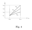
- FIG. 4 is a characteristic curve diagram illustrating control characteristics according to one exemplary preferred embodiment of the present invention.
- FIG. 5 is a characteristic curve diagram illustrating torque-related control characteristics according to one exemplary preferred embodiment of the present invention.
- FIG. 6 is a block diagram illustrating the detailed configuration of a position speed estimating calculator according to one exemplary preferred embodiment of the present invention.
- FIG. 7 is a block diagram illustrating the specific detailed configuration of a fan motor drive device according to one exemplary preferred embodiment of the present invention.
- FIG. 8 is a view used in explaining the block diagram illustrated in FIG. 7 .
- FIG. 9 is a block diagram illustrating a fan motor drive device according to another exemplary preferred embodiment of the present invention.
- a motor is driven so as to maintain a wind volume at a constant value indicated by a control target value, thus correcting the variation of the wind volume with respect to the control target value, which may be caused by the inter-motor variation.
- the wind volume (flow rate) related to blowing is Q
- the revolution number of a motor used in blowing is N [r/min]
- the output of the motor is P [W]
- the wind volume Q, the revolution number N and the output P are expressed by a proportional relationship and are represented by a relational expression of the following equation. Equation 1 QN 2 ⁇ P (1)
- the revolution number N and the output P are converted to physical quantities used in vector control.
- the revolution number N may be represented by the following equation using an electrical angular velocity ⁇ e [rad/sec] and a pole pair number P P of a motor.
- Equation ⁇ ⁇ 3 N 60 2 ⁇ ⁇ ⁇ ⁇ p P ⁇ ⁇ e ( 3 )
- Equation ⁇ ⁇ 6 ⁇ m 1 P P ⁇ ⁇ e ( 6 )
- the flow coefficient K′ Q is represented by the following equation.
- Equation ⁇ ⁇ 10 K Q ′ ( 60 2 ⁇ ⁇ ⁇ ⁇ p P ) 2 ⁇ 1 ⁇ ⁇ K Q ( 10 )
- FIG. 1 is a block diagram illustrating the basic configuration of a fan motor drive device according to one exemplary preferred embodiment of the present invention.
- the fan motor drive device 1 may be applied to an air blower device (or any other desirable blower or fan device) which blows air by driving a centrifugal fan with a three-phase brushless DC motor 2 .
- an AC power supply 4 is rectified by a rectifier circuit 3 defined by a full-wave rectifier circuit and provided with diodes D 1 to D 4 . Thereafter, the rectified current is smoothened by a smoothening capacitor C, thus generating a DC power supply (a bus voltage) VBus and supplying the DC power supply VBus to an inverter 5 .
- three sets of serial circuits defined by drive elements 7 U, 7 V, 7 W, 8 U, 8 V and 8 W such as transistors or field effect transistors (FET) are set so that the drive currents thereof are able to be detected by a current sensor 11 , and are disposed between the DC power supply V BUS and the current sensor 11 .
- the connection midpoints of the respective serial circuits are connected to U-phase, V-phase and W-phase coils of a motor 2 .
- the current sensor 11 is connected to a ground line.
- the bases (gates) of the respective drive elements 7 U, 7 V, 7 W, 8 U, 8 V and 8 W are preferably driven by a drive circuit (not illustrated), whereby the motor 2 is driven by the output voltages of the drive elements 7 U, 7 V, 7 W, 8 U, 8 V and 8 W.
- the current sensor 11 is preferably installed in series between the inverter 5 and a ground line to detect the drives currents of the respective phases of the motor 2 .
- a protective diode is preferably provided in each of the drive elements 7 U, 7 V, 7 W, 8 U, 8 V and 8 W.
- a low-voltage DC power supply is generated from the AC power supply by a power supply circuit (not illustrated) and is inputted to a control circuit 9 , which preferably includes a microcomputer, a microcontroller, a microprocessor, etc.
- the control circuit 9 acquires a drive current of the motor 2 from the current sensor 11 and determines a drive voltage of the motor 2 through the vector control calculation based on the drive current information, thus controlling the operation of the inverter 5 .
- FIG. 2 is a block diagram illustrating, together with peripheral configurations, the functional blocks configured by the execution of processing sequences of the control circuit 9 . Moreover, FIG. 2 is a block diagram illustrating the configuration which is the premise of the present invention.
- the control circuit 9 drives the motor 2 by the configurations of the functional blocks using a sensor-less vector control method.
- the fan motor drive device 1 inputs a drive current i uv of each phase detected by the current sensor 11 to a Clarke transformer 12 .
- the Clarke transformer 12 outputs a drive current vector i ⁇ of a two-phase fixed coordinate system by Clarke-transforming the detection result obtained by the current sensor 11 .
- a position speed estimating calculator 13 acquires a current rotation angle and a current rotation speed of the motor 2 by estimating and calculating a rotation angle ⁇ e and an electrical angular velocity ⁇ e of a rotor from the drive voltage vector V ⁇ of the two-phase fixed coordinate system corresponding to the drive current vector i ⁇ of the two-phase fixed coordinate system and outputting the rotation angle ⁇ e and an electrical angular velocity ⁇ e .
- a calculator (sin/cos) 15 calculates and outputs sine and cosine values of the rotation angle ⁇ e calculated in the position speed estimating calculator 13 .
- a Park transformer 14 converts the drive current vector i q to a q-axis drive current i q and a d-axis drive current i d of a rotary coordinate system and outputs the q-axis drive current i q and the d-axis drive current i d by Park-transforming the drive current vector i ⁇ of the two-phase fixed coordinate system using the calculation result of the calculator 15 .
- the flow coefficient K′ Q according to equation 9 is inputted as a wind volume control target value from a host controller.
- a multiplier 16 multiplies the flow coefficient K′ Q and the electrical angular velocity ⁇ e calculated in the position speed estimating calculator 13 .
- the fan motor drive device 1 executes the multiplying process of the left side of equation 9 and outputs a wind-volume-constant target drive current value i q as a control target drive current to a subtracting circuit 18 via a switch 17 .
- the subtracting circuit 18 subtracts the q-axis drive current i q calculated in the Park transformer 14 from the output value of the switch 17 and outputs the subtracted value.
- a PI controller (PI) 19 amplifies the output value of the subtracting circuit 18 with a predetermined gain and calculates a moving integral value of the output value of the subtracting circuit 18 . Thereafter, the moving integral value is amplified by a predetermined gain and is added, thus calculating a q-axis drive voltage V q which is a control value related to proportional integral control.
- a subtracting circuit 20 calculates and outputs a subtracted value of the control target value i1 d (which is 0 in this example) corresponding to the d-axis drive current i d calculated in the Park transformer 14 .
- a PI controller (PI) 21 calculates and outputs a d-axis drive voltage V d which is a control value related to the proportional integral control of the subtracting circuit 20 .
- an inverse Park transformer 22 inversely Park-transforms the q-axis drive voltage V q and the d-axis drive voltage V d outputted from the PI controllers 19 and 21 and outputs a drive voltage vector V ⁇ of a two-phase fixed coordinate system.
- An inverse Clarke transformer 23 inversely Clarke-transforms the drive voltage vector V ⁇ of the two-phase fixed coordinate system outputted from the inverse Park transformer 22 and outputs a drive voltage vector V UVW of a three-phase fixed coordinate system.
- the drive voltage vector V UVW of the three-phase fixed coordinate system outputted from the inverse Clarke transformer 23 is pulse-width-modulated and applied to coils of the motor 2 , thus driving the motor 2 .
- the fan motor drive device 1 performs feed-back control so that the multiplied value of the flow coefficient K′ Q inputted from a host controller and the electric angular velocity ⁇ e becomes a wind-volume-constant q-axis target drive current i1 q and the drive current i q matches with the wind-volume-constant q-axis target drive current i1 q .
- the fan motor drive device 1 drives the motor 2 so as to maintain the relational expression of equation 9, consequently driving the motor 2 by wind-volume-constant control.
- the Clarke transformer 12 , the calculator 15 , the Park transformer 14 , the subtracting circuits 18 and 20 , the PI controllers 19 and 21 , the inverse Park transformer 22 and the inverse Clarke transformer 23 define a current vector controller 25 which controls the drive current of the motor 2 according to a control target.
- a speed control target value is inputted to a subtracting circuit 26 by changing a speed upper limit value ⁇ max and a speed lower limit value ⁇ min .
- a subtracted value is calculated by subtracting the speed control target value from the electric angular velocity ⁇ e estimated in the position speed estimating calculator 13 .
- the subtracted value thus calculated is inputted to a PI controller 27 to calculate a speed-constant q-axis target drive current i1 q related to the proportional integral control.
- the calculation result is outputted to the switch 17 .
- the electric angular velocity ⁇ e estimated in the position speed estimating calculator 13 is determined by a determination processor (not illustrated).
- the operation of the switch 17 and the speed control target value are switched depending on the determination result.
- the control of the motor 2 is switched between wind-volume-constant control and speed-constant control, thus driving the motor 2 so that the rotation speed of the motor 2 does not exceed the upper limit value and the lower limit value.
- the determination processor sets the speed control target value at the upper limit value ⁇ max and switches the operation of the switch 17 so that the output value of the PI controller 27 is outputted to the subtracting circuit 18 .
- the control of the motor 2 is switched from the wind-volume-constant control to the speed-constant control, thus maintaining the rotation speed of the motor 2 at the upper limit value ⁇ max .
- the switch 17 is configured to switch the control of the motor 2 from the speed-constant control to the wind-volume-constant control.
- the speed control target value is set at the lower limit value ⁇ min and the operation of the switch 17 is switched so that the output value of the PI controller 27 is outputted to subtracting circuit 18 .
- the control of the motor 2 is switched from the wind-volume-constant control to the speed-constant control, thus maintaining the rotation speed of the motor 2 at the lower limit value ⁇ min .
- the multiplied value is outputted from the multiplier 16 to the subtracting circuit 18 via the switch 17 , thus driving the motor 2 by the wind-volume-constant control. That is to say, the switch 17 switches the control of the motor 2 from the speed-constant control to the wind-volume-constant control.
- FIG. 4 is a characteristic curve diagram illustrating the characteristics of the fan motor drive device 1 related to the conversion of drive.
- the motor 2 In the state in which the motor 2 is driven by the wind-volume-constant control, the motor 2 is driven by the characteristic of the drive current and the rotation speed which depends on the proportionality coefficient pursuant to the flow coefficient K′ Q (see the range indicated by solid lines). For example, if the static pressure within a flow path grows higher in this state, the rotation speed of the motor 2 is increased in order to keep the wind volume constant. At this time, if the rotation speed of the motor 2 exceeds the upper limit value, the drive of the motor 2 is switched to the drive using the speed-constant control, whereby the motor 2 is driven at the upper limit value (see the range indicated by a broken line).
- the rotation speed of the motor 2 is reduced in order to keep the wind volume constant. In this case, if the rotation speed of the motor 2 becomes lower than the lower limit value, the drive of the motor 2 is switched to the drive using the speed-constant control, thus driving the motor 2 at the lower limit value. If the static pressure within a flow path grows larger in a state in which the motor 2 is driven at the lower limit value of the rotation speed by the speed-constant control, the load of the motor 2 becomes smaller and the drive current is reduced. In this case, if the magnitude of the drive current is smaller than the multiplied value of the flow coefficient and the rotation speed, the drive of the motor 2 is switched to the drive using the original wind-volume-constant control (see the range indicated by a broken line).
- the fan motor drive device 1 drives the motor 2 in a controller (a wind-pressure-constant controller) in which the motor 2 is driven by wind-pressure-constant control and other controllers (a high-speed controller and a low-speed controller) in which the motor 2 is driven at a high speed and a low speed.
- a controller a wind-pressure-constant controller
- other controllers a high-speed controller and a low-speed controller
- the motor is driven by vector control.
- the target drive current is calculated by multiplying the current rotation speed and the flow coefficient. Feed-back control is performed such that the target drive current matches with the actual drive current.
- the aforementioned configuration is effective in controlling a wind volume in a centrifugal fan such as a blower or the like.
- the method of adjusting the flow coefficient may be, for example, a method in which a volume knob or the like is installed within a fan motor drive device and a flow coefficient is adjusted by operating the volume knob, or a method in which the magnitude of a wind volume is instructed from a host controller or the like.
- FIG. 6 is a block diagram specifically illustrating the configuration of the position speed estimating calculator 13 .
- a rotor magnetic flux estimator 13 A calculates an estimated value ⁇ m ⁇ of a rotor magnetic flux intensity from a drive current vector i ⁇ and a drive voltage vector V ⁇ of a two-phase fixed coordinate system and an electric angular velocity ⁇ e . Even if the internal parameters (nominal values of a resistance and an inductance) of the rotor magnetic flux estimator 13 A slightly differ from actual values, the rotor magnetic flux estimator 13 A feed-back calculates the estimated value ⁇ m ⁇ so that the estimated value ⁇ m ⁇ gradually comes close to an actual value. Thus, the estimated value ⁇ m ⁇ reflects the actual value.
- a calculator 13 B calculates a rotation angle ⁇ e of a rotor by a calculation process of the following equation and outputs the rotation angle ⁇ e .
- Equation ⁇ ⁇ 11 ⁇ e tan - 1 ⁇ ( ⁇ m ⁇ ⁇ ⁇ ⁇ m ⁇ ⁇ ⁇ ) ( 11 )
- a velocity estimator 13 C calculates an electric angular velocity ⁇ e using the rotation angle ⁇ e found in the calculator 13 B.
- the position speed estimating calculator 13 outputs the rotation angle ⁇ e found in the calculator 13 B and the electric angular velocity ⁇ e found in the velocity estimator 13 C, to the calculator 15 .
- the fan motor drive device 1 is configured to drive the motor 2 by detecting the rotational position of the rotor in a sensor-less manner.
- FIG. 7 is a block diagram illustrating, in contrast with FIG. 2 , the specific configuration of a fan motor drive device according to one exemplary preferred embodiment of the present invention.
- the fan motor drive device 1 illustrated in FIG. 2 preferably controls the electric angular velocity ⁇ e and the q-axis drive current i q so that they are maintained in a proportional relationship, consequently driving the motor 2 by the wind-volume-constant control.
- the torque ⁇ is denoted by the product of the pole pair number P P , the rotor magnetic flux intensity ⁇ [Vs/rad] and the q-axis drive current i q .
- the pole pair number P P and the rotor magnetic flux intensity ⁇ [Vs/rad] are values corresponding to the torque constant of the motor.
- the torque ⁇ is changed in proportion to the drive current i q .
- the rotor magnetic flux intensity ⁇ varies due to the deviation of magnetization, the deviation of air gaps, etc. This deviation is said to typically be about ⁇ 10%, for example. Therefore, even if the drive current i q is accurately controlled, the generated torque varies from motor to motor in the fan motor drive device 1 . As a result, with respect to the control target value indicated by the flow coefficient K′ Q , the wind volume actually kept at a constant value by the wind-volume-constant control largely varies from motor to motor.
- the position speed estimating calculator 13 detects the estimated value of the rotor magnetic flux intensity. The torque is controlled by effectively using the estimated value acquired in the position speed estimating calculator 13 .
- a multiplier 16 A and a PI controller 27 A are preferably provided in place of the multiplier 16 and the PI controller 27 . Furthermore, a command converter 31 and a Park transformer 32 are additionally provided.
- it is necessary to Park-transform the estimated value ⁇ m ⁇ of the rotor magnetic flux intensity acquired in the position speed estimating calculator 13 by indicating the estimated value ⁇ m ⁇ in a vector quantity on a fixed rectangular coordinate system (or a ⁇ coordinate system). It is also necessary to detect the magnitude of a magnetic flux (a d-axis component) ⁇ md represented by the following equation. Equation 12 ⁇ md ⁇ m ⁇ ⁇ cos ⁇ e + ⁇ m ⁇ ⁇ sin ⁇ e (12)
- the fan motor drive device 30 inputs the sine and cosine values of the rotation angle ⁇ e outputted from the calculator 15 , to the Park transformer 32 .
- the Park transformer 32 acquires the estimated value ⁇ md of the rotor magnetic flux intensity by the calculation process of equation 12.
- the multiplier 16 A converts the flow coefficient K′ Q , which is a control target value pursuant to a q-axis current, to a torque command value ⁇ q by the calculation process of the following equation using the flow coefficient K′ Q and the electric angular velocity ⁇ e calculated in the position speed estimating calculator 13 , and outputs the torque command value ⁇ q thus converted.
- the fan motor drive device 30 changes the output value of the switch 17 pursuant to the estimated value ⁇ md of the rotor magnetic flux intensity by allowing the command converter 31 to execute the calculation process of the following equation with respect to the control target value pursuant to the torque command value ⁇ q outputted from the switch 17 . Accordingly, the fan motor drive device 30 is capable of effectively avoiding the variation of the generated torque attributable to the variation of the rotor magnetic flux intensity, thus driving the motor 2 by the wind-volume-constant control using the wind volume corresponding to the flow coefficient K′ Q which is a control indication value.
- Equation ⁇ ⁇ 14 i q ⁇ p P ⁇ ⁇ red ( 14 )
- the fan motor drive device 30 controls the drive current of the motor 2 by the feedback control illustrated in FIG. 8 in contrast with FIG. 3 .
- the control amount is changed by changing the control target value based on the estimated value of the rotor magnetic flux intensity acquired in the position speed estimating calculator. This makes it possible to sufficiently reduce the change in the generated torque attributable to the variation of the rotor magnetic flux intensity.
- FIG. 9 is a block diagram illustrating, in contrast with FIG. 7 , a fan motor drive device according to another exemplary preferred embodiment of the present invention.
- the control amount is changed by changing the feedback value related to feedback control instead of changing the control target value, thus reducing the change in the generated torque attributable to the variation of the rotor magnetic flux intensity.
- the fan motor drive device 40 is identical in configuration with the fan motor drive device 1 according to one exemplary preferred embodiment of the present invention except the difference in the configuration related to the change of the feedback value.
- PI controllers 19 A and 21 A generate a drive-voltage-dependent control value from the torque-value-dependent control value outputted from the subtracting circuits 18 and 20 and output the drive-voltage-dependent control value.
- All of the above described components may be implemented by using: (i) a microcontroller which has been programmed to include functional blocks which correspond to the above components, (ii) a microcontroller which has been programmed to include functional blocks which correspond to some of the above components and which is connected to discrete electrical circuitry which provides the remaining components, and (iii) any other arrangement of a microcontroller, microprocessor, computer, etc. and any desired discrete electrical circuitry.
- control target value and the feedback value are adjusted depending on the rotor magnetic flux intensity found in the position speed estimating calculator.
- present invention is not limited thereto.
- the control target value and the feedback value may be adjusted by separately detecting the rotor magnetic flux intensity.
- the position speed estimating calculator to acquire a rotation angle and a rotation speed of a motor is provided to acquire a rotation angle and a rotation speed by the estimation and calculation from a drive current and a drive voltage.
- a position sensor such as an encoder or a resolver may be provided to acquire a rotation angle and a rotation speed.
- a rotation angle and a rotation speed may be acquired by processing the detection result of the position sensor.
- the current vector controller 25 used in vector control preferably is configured by the Clarke transformer 12 , the calculator 15 , the Park transformer 14 , the subtracting circuits 18 and 20 , the PI controllers 19 and 21 , the inverse Park transformer 22 and the inverse Clarke transformer 23 , for example.
- the present invention is not limited thereto but may be widely applied to a case where a current vector controller is configured by calculating a Clarke transformation processing result and a Park transformation processing result through approximate calculation processing.
- the present invention is preferably applied to the air blower device which transfers a gas by diving a fan.
- the present invention is not limited thereto but may be widely applied to a case where a liquid is transferred by driving a fan (an impeller). This makes it possible to drive the fan by flow-rate-constant control.
Abstract
Description
Equation 1
QN 2 ∝P (1)
K Q ·N 2 =P (2)
Equation 4
P=τω m (4)
Equation 5
τ=p p ·Φ·i q (5)
Equation 7
P=Φ·i q·ωe (7)
Equation 9
K′ Q·ωe =i q (9)
φmd=φmα·cos θe+φmβ·sin θe (12)
τ=K Q·ωe (13)
[τdτq]r =p p·φmd ·[i d i q]T (15)
Claims (12)
Applications Claiming Priority (2)
| Application Number | Priority Date | Filing Date | Title |
|---|---|---|---|
| JP2014128968A JP6462241B2 (en) | 2014-06-24 | 2014-06-24 | Fan motor driving device and blower |
| JP2014-128968 | 2014-06-24 |
Publications (2)
| Publication Number | Publication Date |
|---|---|
| US20150372630A1 US20150372630A1 (en) | 2015-12-24 |
| US9461576B2 true US9461576B2 (en) | 2016-10-04 |
Family
ID=54870562
Family Applications (1)
| Application Number | Title | Priority Date | Filing Date |
|---|---|---|---|
| US14/747,324 Active US9461576B2 (en) | 2014-06-24 | 2015-06-23 | Fan motor drive device and blower device |
Country Status (3)
| Country | Link |
|---|---|
| US (1) | US9461576B2 (en) |
| JP (1) | JP6462241B2 (en) |
| CN (1) | CN105227020B (en) |
Cited By (2)
| Publication number | Priority date | Publication date | Assignee | Title |
|---|---|---|---|---|
| US11143427B2 (en) | 2018-10-26 | 2021-10-12 | Johnson Controls Technology Company | Fan motor control |
| US11168916B2 (en) | 2018-06-11 | 2021-11-09 | Broan-Nutone Llc | Ventilation system with automatic flow balancing derived from a neural network and methods of use |
Families Citing this family (10)
| Publication number | Priority date | Publication date | Assignee | Title |
|---|---|---|---|---|
| US10053317B2 (en) * | 2016-08-08 | 2018-08-21 | Ricoh Company, Ltd. | Contact-and-separation system, image forming apparatus, and contact-and-separation method |
| DE112017004500T5 (en) * | 2016-09-07 | 2019-06-13 | Nidec Corporation | Engine control method, engine control system and electric power steering system |
| CN107725460B (en) * | 2017-11-21 | 2023-11-03 | 江苏徐工工程机械研究院有限公司 | Fan control system and dust suppression vehicle |
| JP2019103310A (en) * | 2017-12-05 | 2019-06-24 | シナノケンシ株式会社 | Motor device and on-vehicle seat air conditioner |
| CN108512477B (en) * | 2018-05-25 | 2020-06-02 | 北京新能源汽车股份有限公司 | Diagnosis method, device and equipment for motor rotor position sampling |
| EP3806320A4 (en) * | 2018-05-30 | 2021-06-09 | Mitsubishi Electric Corporation | Permanent-magnet synchronous motor and ventilation blower |
| US11754084B2 (en) | 2019-03-04 | 2023-09-12 | Minebea Mitsumi Inc. | Motor drive control device using feedback speed control and motor current control |
| JP7257186B2 (en) * | 2019-03-04 | 2023-04-13 | ミネベアミツミ株式会社 | MOTOR DRIVE CONTROL DEVICE, FAN, AND MOTOR DRIVE CONTROL METHOD |
| JP7256033B2 (en) * | 2019-03-04 | 2023-04-11 | ミネベアミツミ株式会社 | MOTOR DRIVE CONTROL DEVICE, FAN, AND MOTOR DRIVE CONTROL METHOD |
| US20230336097A1 (en) * | 2022-04-13 | 2023-10-19 | Haier Us Appliance Solutions, Inc. | Method for power limiting an appliance motor |
Citations (5)
| Publication number | Priority date | Publication date | Assignee | Title |
|---|---|---|---|---|
| JP2004096979A (en) | 2002-08-31 | 2004-03-25 | C & S Kokusai Kenkyusho:Kk | Method for vector control of synchronous motor and device using the same |
| US20070053769A1 (en) * | 2005-09-06 | 2007-03-08 | Schlanger Steven E | System for powering a vehicle air temperature control system air mover, and related method |
| JP2008043083A (en) | 2006-08-08 | 2008-02-21 | Matsushita Electric Ind Co Ltd | Constant-air flow control direct-current fan motor driving device |
| US20090104034A1 (en) | 2005-10-04 | 2009-04-23 | Matsushita Electric Industrial Co., Ltd | Blower and electric device with such blower mounted thereon |
| US20110000652A1 (en) | 2008-03-06 | 2011-01-06 | Panasonic Corporation | Ventilation device and electrical equipment in which same is installed |
Family Cites Families (7)
| Publication number | Priority date | Publication date | Assignee | Title |
|---|---|---|---|---|
| JP3738685B2 (en) * | 2000-11-21 | 2006-01-25 | 三菱電機株式会社 | Inverter device and blower device |
| US20060043923A1 (en) * | 2004-08-31 | 2006-03-02 | Baker Donal E | Performance enhancement for motor field oriented control system |
| JP5161612B2 (en) * | 2008-02-22 | 2013-03-13 | 株式会社東芝 | Permanent magnet type rotating electrical machine, method for assembling permanent magnet type rotating electrical machine, and method for disassembling permanent magnet type rotating electrical machine |
| CN101931353B (en) * | 2010-01-29 | 2013-05-22 | 梁伟 | Control method for brushless direct current motor for automotive air conditioning fan |
| CN201667628U (en) * | 2010-02-11 | 2010-12-08 | 利德国际企业有限公司 | Brushless direct-current motor and control device thereof as well as commercial indoor air conditioner using the same |
| CN102315809B (en) * | 2010-07-08 | 2016-11-16 | 德昌电机(深圳)有限公司 | Dynamo of fan, air flow property regulation equipment and air quantity control method |
| CN103809437B (en) * | 2012-11-13 | 2016-06-29 | 中山大洋电机股份有限公司 | A kind of constant air capacity control of motor |
-
2014
- 2014-06-24 JP JP2014128968A patent/JP6462241B2/en active Active
-
2015
- 2015-06-23 US US14/747,324 patent/US9461576B2/en active Active
- 2015-06-24 CN CN201510354531.5A patent/CN105227020B/en active Active
Patent Citations (5)
| Publication number | Priority date | Publication date | Assignee | Title |
|---|---|---|---|---|
| JP2004096979A (en) | 2002-08-31 | 2004-03-25 | C & S Kokusai Kenkyusho:Kk | Method for vector control of synchronous motor and device using the same |
| US20070053769A1 (en) * | 2005-09-06 | 2007-03-08 | Schlanger Steven E | System for powering a vehicle air temperature control system air mover, and related method |
| US20090104034A1 (en) | 2005-10-04 | 2009-04-23 | Matsushita Electric Industrial Co., Ltd | Blower and electric device with such blower mounted thereon |
| JP2008043083A (en) | 2006-08-08 | 2008-02-21 | Matsushita Electric Ind Co Ltd | Constant-air flow control direct-current fan motor driving device |
| US20110000652A1 (en) | 2008-03-06 | 2011-01-06 | Panasonic Corporation | Ventilation device and electrical equipment in which same is installed |
Cited By (2)
| Publication number | Priority date | Publication date | Assignee | Title |
|---|---|---|---|---|
| US11168916B2 (en) | 2018-06-11 | 2021-11-09 | Broan-Nutone Llc | Ventilation system with automatic flow balancing derived from a neural network and methods of use |
| US11143427B2 (en) | 2018-10-26 | 2021-10-12 | Johnson Controls Technology Company | Fan motor control |
Also Published As
| Publication number | Publication date |
|---|---|
| US20150372630A1 (en) | 2015-12-24 |
| JP6462241B2 (en) | 2019-01-30 |
| CN105227020B (en) | 2018-06-29 |
| CN105227020A (en) | 2016-01-06 |
| JP2016010218A (en) | 2016-01-18 |
Similar Documents
| Publication | Publication Date | Title |
|---|---|---|
| US9461576B2 (en) | Fan motor drive device and blower device | |
| US9590552B2 (en) | Motor drive device and electric compressor | |
| JP4928850B2 (en) | Rotating machine control device | |
| KR101678323B1 (en) | Motor drive control device | |
| US9797406B2 (en) | Motor device | |
| WO2012111504A1 (en) | Motor controller | |
| JP2009038921A (en) | Sensorless controller for brushless motor | |
| US20190173413A1 (en) | Motor module, motor controller, temperature inferring device, and temperature inference method | |
| JP6514683B2 (en) | Motor device | |
| WO2017126639A1 (en) | Abnormality detection device for current sensor | |
| WO2017061612A1 (en) | Synchronous electric motor control device, integrated electric motor system, pump system, and positioning system | |
| JP5193012B2 (en) | Motor temperature estimation device | |
| JP4791319B2 (en) | Inverter device, compressor drive device and refrigeration / air-conditioning device | |
| JP2009290962A (en) | Controller of permanent magnet type synchronous motor | |
| JP6929460B2 (en) | Permanent magnet synchronous motor and ventilation blower | |
| JP2004040861A (en) | Driving-gear of motor | |
| JP2012165547A (en) | Motor drive device | |
| US20230142956A1 (en) | Motor controller, motor system and method for controlling motor | |
| JP5332301B2 (en) | Control device for permanent magnet type synchronous motor | |
| WO2022137406A1 (en) | Ventilation blower | |
| JP2022101783A (en) | Control device, motor system, and identification method | |
| JP2022101781A (en) | Control device, motor system, and identification method | |
| JP2022101784A (en) | Control device, motor system, and identification method | |
| JP2016127697A (en) | Motor control device and power generator control device | |
| JP2006087263A (en) | Control method and device of synchronous motor |
Legal Events
| Date | Code | Title | Description |
|---|---|---|---|
| AS | Assignment |
Owner name: NIDEC SERVO CORPORATION, JAPAN Free format text: ASSIGNMENT OF ASSIGNORS INTEREST;ASSIGNOR:ISHIKAWA, MASATOMO;REEL/FRAME:035884/0652 Effective date: 20150610 |
|
| STCF | Information on status: patent grant |
Free format text: PATENTED CASE |
|
| MAFP | Maintenance fee payment |
Free format text: PAYMENT OF MAINTENANCE FEE, 4TH YEAR, LARGE ENTITY (ORIGINAL EVENT CODE: M1551); ENTITY STATUS OF PATENT OWNER: LARGE ENTITY Year of fee payment: 4 |
|
| MAFP | Maintenance fee payment |
Free format text: PAYMENT OF MAINTENANCE FEE, 8TH YEAR, LARGE ENTITY (ORIGINAL EVENT CODE: M1552); ENTITY STATUS OF PATENT OWNER: LARGE ENTITY Year of fee payment: 8 |