US9459578B2 - Image forming apparatus - Google Patents
Image forming apparatus Download PDFInfo
- Publication number
- US9459578B2 US9459578B2 US14/851,613 US201514851613A US9459578B2 US 9459578 B2 US9459578 B2 US 9459578B2 US 201514851613 A US201514851613 A US 201514851613A US 9459578 B2 US9459578 B2 US 9459578B2
- Authority
- US
- United States
- Prior art keywords
- toner
- image
- image forming
- forming apparatus
- area coverage
- Prior art date
- Legal status (The legal status is an assumption and is not a legal conclusion. Google has not performed a legal analysis and makes no representation as to the accuracy of the status listed.)
- Active
Links
Images


Classifications
-
- G—PHYSICS
- G03—PHOTOGRAPHY; CINEMATOGRAPHY; ANALOGOUS TECHNIQUES USING WAVES OTHER THAN OPTICAL WAVES; ELECTROGRAPHY; HOLOGRAPHY
- G03G—ELECTROGRAPHY; ELECTROPHOTOGRAPHY; MAGNETOGRAPHY
- G03G15/00—Apparatus for electrographic processes using a charge pattern
- G03G15/65—Apparatus which relate to the handling of copy material
- G03G15/6582—Special processing for irreversibly adding or changing the sheet copy material characteristics or its appearance, e.g. stamping, annotation printing, punching
- G03G15/6585—Special processing for irreversibly adding or changing the sheet copy material characteristics or its appearance, e.g. stamping, annotation printing, punching by using non-standard toners, e.g. transparent toner, gloss adding devices
-
- G—PHYSICS
- G03—PHOTOGRAPHY; CINEMATOGRAPHY; ANALOGOUS TECHNIQUES USING WAVES OTHER THAN OPTICAL WAVES; ELECTROGRAPHY; HOLOGRAPHY
- G03G—ELECTROGRAPHY; ELECTROPHOTOGRAPHY; MAGNETOGRAPHY
- G03G15/00—Apparatus for electrographic processes using a charge pattern
- G03G15/50—Machine control of apparatus for electrographic processes using a charge pattern, e.g. regulating differents parts of the machine, multimode copiers, microprocessor control
- G03G15/5025—Machine control of apparatus for electrographic processes using a charge pattern, e.g. regulating differents parts of the machine, multimode copiers, microprocessor control by measuring the original characteristics, e.g. contrast, density
-
- G—PHYSICS
- G03—PHOTOGRAPHY; CINEMATOGRAPHY; ANALOGOUS TECHNIQUES USING WAVES OTHER THAN OPTICAL WAVES; ELECTROGRAPHY; HOLOGRAPHY
- G03G—ELECTROGRAPHY; ELECTROPHOTOGRAPHY; MAGNETOGRAPHY
- G03G15/00—Apparatus for electrographic processes using a charge pattern
- G03G15/14—Apparatus for electrographic processes using a charge pattern for transferring a pattern to a second base
- G03G15/16—Apparatus for electrographic processes using a charge pattern for transferring a pattern to a second base of a toner pattern, e.g. a powder pattern, e.g. magnetic transfer
- G03G15/1605—Apparatus for electrographic processes using a charge pattern for transferring a pattern to a second base of a toner pattern, e.g. a powder pattern, e.g. magnetic transfer using at least one intermediate support
-
- G—PHYSICS
- G03—PHOTOGRAPHY; CINEMATOGRAPHY; ANALOGOUS TECHNIQUES USING WAVES OTHER THAN OPTICAL WAVES; ELECTROGRAPHY; HOLOGRAPHY
- G03G—ELECTROGRAPHY; ELECTROPHOTOGRAPHY; MAGNETOGRAPHY
- G03G15/00—Apparatus for electrographic processes using a charge pattern
- G03G15/14—Apparatus for electrographic processes using a charge pattern for transferring a pattern to a second base
- G03G15/16—Apparatus for electrographic processes using a charge pattern for transferring a pattern to a second base of a toner pattern, e.g. a powder pattern, e.g. magnetic transfer
- G03G15/1665—Apparatus for electrographic processes using a charge pattern for transferring a pattern to a second base of a toner pattern, e.g. a powder pattern, e.g. magnetic transfer by introducing the second base in the nip formed by the recording member and at least one transfer member, e.g. in combination with bias or heat
- G03G15/167—Apparatus for electrographic processes using a charge pattern for transferring a pattern to a second base of a toner pattern, e.g. a powder pattern, e.g. magnetic transfer by introducing the second base in the nip formed by the recording member and at least one transfer member, e.g. in combination with bias or heat at least one of the recording member or the transfer member being rotatable during the transfer
- G03G15/168—Apparatus for electrographic processes using a charge pattern for transferring a pattern to a second base of a toner pattern, e.g. a powder pattern, e.g. magnetic transfer by introducing the second base in the nip formed by the recording member and at least one transfer member, e.g. in combination with bias or heat at least one of the recording member or the transfer member being rotatable during the transfer with means for conditioning the transfer element, e.g. cleaning
-
- G—PHYSICS
- G03—PHOTOGRAPHY; CINEMATOGRAPHY; ANALOGOUS TECHNIQUES USING WAVES OTHER THAN OPTICAL WAVES; ELECTROGRAPHY; HOLOGRAPHY
- G03G—ELECTROGRAPHY; ELECTROPHOTOGRAPHY; MAGNETOGRAPHY
- G03G2215/00—Apparatus for electrophotographic processes
- G03G2215/01—Apparatus for electrophotographic processes for producing multicoloured copies
- G03G2215/0103—Plural electrographic recording members
- G03G2215/0119—Linear arrangement adjacent plural transfer points
- G03G2215/0122—Linear arrangement adjacent plural transfer points primary transfer to an intermediate transfer belt
- G03G2215/0125—Linear arrangement adjacent plural transfer points primary transfer to an intermediate transfer belt the linear arrangement being horizontal or slanted
- G03G2215/0129—Linear arrangement adjacent plural transfer points primary transfer to an intermediate transfer belt the linear arrangement being horizontal or slanted horizontal medium transport path at the secondary transfer
Definitions
- the present invention relates to an image forming apparatus.
- an image forming apparatus including a forming unit that forms a toner image with a substantially flat toner containing a substantially flat metal pigment on a movable body; a transfer unit that forms a nip with the movable body and transfers the toner image on a medium transported to the nip; and a controller that, if at least one of first and second conditions, the first condition in which an image width from data for allowing the forming unit to form the toner image is larger than a predetermined width, the second condition in which an area coverage from the data is higher than a predetermined area coverage, is satisfied, causes the forming unit to form a toner image with a corrected area coverage lower than the area coverage from the data.
- FIG. 1 is schematic view (front view) of an image forming apparatus according to a first exemplary embodiment
- FIG. 2 is a schematic view (front view) of a toner image forming unit configuring the image forming apparatus according to the first exemplary embodiment
- FIG. 3 is a schematic view of a peripheral area of a second transfer unit of a transfer device configuring the image forming apparatus according to the first exemplary embodiment
- FIG. 4 is a schematic view (cross-sectional view) of a toner particle of a flat toner that is used by the image forming apparatus according to the first exemplary embodiment
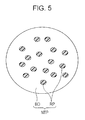
- FIG. 5 is a schematic view (cross-sectional view) of a toner particle of a non-flat toner that is used by the image forming apparatus according to the first exemplary embodiment
- FIGS. 6A and 6B are each an illustration showing a flat toner held on a transfer belt of the image forming apparatus according to the first exemplary embodiment, FIG. 6A being a schematic view showing a flat toner configuring a toner image within a dotted-line area 6 A in FIG. 1 , FIG. 6B being a schematic view showing a flat toner configuring a toner image within a dotted-line area 6 B in FIG. 1 ;
- FIG. 7 is a flowchart of control that is executed during an operation of image formation by a controller configuring the image forming apparatus according to the first exemplary embodiment
- FIG. 8 is a schematic view showing a predetermined condition of the controller in the flowchart in FIG. 7 , in the image forming apparatus according to the first exemplary embodiment
- FIG. 9 is a graph showing a test result that serves as the basis of the predetermined condition in FIG. 8 ;
- FIG. 10 is a graph showing a test result that serves as the basis of the predetermined condition in FIG. 8 ;
- FIG. 11A is a schematic view showing an image on a medium formed by an image forming apparatus according to a comparative exemplary embodiment
- FIG. 11B is a partial cross-sectional view taken along line XIB-XIB in FIG. 11A
- FIG. 11C is a partial cross-sectional view taken along line XIC-XIC in FIG. 11A ;
- FIG. 12 is a flowchart of control that is executed during an operation of image formation by a controller configuring an image forming apparatus according to another exemplary embodiment
- FIG. 13 is a flowchart of control that is executed during an operation of image formation by a controller configuring an image forming apparatus according to still another exemplary embodiment.
- FIG. 14 is a flowchart of control that is executed during an operation of image formation by a controller configuring an image forming apparatus according to yet another exemplary embodiment.
- exemplary embodiment for implementing the invention (hereinafter, referred to as exemplary embodiment) is described below.
- exemplary embodiment An exemplary embodiment for implementing the invention (hereinafter, referred to as exemplary embodiment) is described below.
- a configuration of an image forming apparatus 10 (see FIG. 1 ) of this exemplary embodiment and a toner (see FIGS. 4 and 5 ) that is used by the image forming apparatus 10 are described.
- an image forming operation of the image forming apparatus 10 of this exemplary embodiment is described.
- effects of this exemplary embodiment are described.
- directions indicated by arrow X and arrow ⁇ X in the drawings represent an apparatus width direction
- directions indicated by arrow Y and arrow ⁇ Y in the drawings represent an apparatus height direction
- directions (arrow Z and arrow ⁇ Z directions) orthogonal to the apparatus width direction and the apparatus height direction represent an apparatus depth direction.
- the image forming apparatus 10 is an apparatus using an electrophotographic system including a toner image forming unit 20 , a transfer device 30 , a transport device 40 , a fixing device 50 , a controller 60 , and a power supply PS.
- the toner image forming unit 20 has a function of forming a toner image G (see FIGS. 1 and 6 ) on a transfer belt TB (described later), which configures the transfer device 30 , by executing respective processes of electric charge, exposure, and development.
- the toner image forming unit 20 includes single-color units 21 G, 21 Y, 21 M, 21 C, and 21 K that form toner images G of different colors (G (gold), Y (yellow), M (magenta), C (cyan), K (black)).
- the single-color units 21 G, 21 Y, 21 M, 21 C, and 21 K have similar configurations except the colors of the respectively formed toner images G.
- the alphabets (G, Y, M, C, K) of the single-color units 21 G, 21 Y, 21 M, 21 C, and 21 K are omitted unless otherwise the single-color units 21 G, 21 Y, 21 M, 21 C, and 21 K and their components are required to be distinguished from one another.
- the single-color unit 21 G forms a toner image G with a flat or substantially flat toner MT (hereinafter, referred to as toner MT, see FIG. 4 ), which is described later, on the transfer belt TB.
- the single-color unit 21 G is an example of a forming unit.
- the single-color units 21 other than the single-color unit 21 G each form a toner image G with a non-flat toner NT (hereinafter, referred to as toner NT, see FIG. 5 ), which is described later, on the transfer belt TB.
- the toner MT and the toner NT of this exemplary embodiment each have, for example, negative polarity (average of charge amount distribution is negative).
- the toners MT and NT are described as a toner T unless otherwise the toner MT and the toner NT are particularly required to be distinguished from one another.
- each single-color unit 21 includes a cylindrical photoconductor 22 , a charging device 24 , an exposure device 26 , a developing device 28 , and a first transfer roller 29 .
- the charging device 24 electrically charges the photoconductor 22
- the exposure device 26 exposes the photoconductor 22 to light
- the developing device 28 develops a toner image G
- the first transfer roller 29 first transfers the toner image G on the moving (circulating) transfer belt TB at a nip N 1 .
- the toner image forming unit 20 forms toner images G on the transfer belt TB.
- a first transfer voltage (voltage with positive polarity) is applied from the power supply PS to each first transfer roller 29 , and hence the first transfer roller 29 first transfers a corresponding toner image G formed on the corresponding photoconductor 22 , on the moving transfer belt TB at the corresponding nip N 1 .
- the exposure device 26 forms, for example, a latent image on the photoconductor 22 with an exposure dot corresponding to 1200 dpi ⁇ 1200 dpi (about 21 ⁇ m ⁇ about 21 ⁇ m).
- the reference signs for the components of the single-color units 21 other than the single-color unit 21 K are omitted.
- the transfer device 30 has a function of second transferring the toner images G of the respective colors formed by the respective single-color units 21 and first transferred at the nips N 1 , on a medium P transported to a nip N 2 (described later). As shown in FIG. 1 , the transfer device 30 includes the transfer belt TB, a driving roller 32 , and a second transfer unit 34 .
- the transfer belt TB is endless.
- the driving roller 32 is driven by a driving source (not shown), and moves the transfer belt TB in arrow R direction while rotating around its axis.
- the toner belt TB causes the toner images G of the respective colors formed by the respective single-color units 21 to reach the nip N 2 while holding the toner images G of the respective colors on the outer periphery.
- the transfer belt TB is an example of a movable body.
- the second transfer unit 34 has a function of second transferring the toner images G of the respective colors held on the transfer belt TB, on a medium P transported by the transport device 40 to the nip N 2 .
- the second transfer unit 34 includes a second transfer portion 70 , a backup roller 80 (hereinafter, referred to as BUR 80 ), and a removing unit 90 .
- the second transfer portion 70 includes a conductive roller 72 , a tension roller 74 , and a conductive belt CB.
- the conductive belt CB has a function of forming the nip N 2 with the transfer belt TB while the conductive belt CB circulates, and transferring a toner image G on a medium P transported to the nip N 2 .
- the conductive belt CB is an example of a transfer unit.
- the conductive roller 72 includes a shaft 72 A, and a cylindrical conductive layer 72 B.
- the conductive roller 72 is driven by a driving source (not shown) and rotates around its axis.
- the conductive belt CB is endless, and is wound around the cylindrical conductive layer 72 B.
- the tension roller 74 presses the conductive belt CB from the inner periphery side, and gives a tension to the conductive belt CB.
- the conductive belt CB circulates while the conductive roller 72 rotates around its axis.
- the shaft 72 A of the conductive roller 72 is grounded.
- the BUR 80 is arranged at the side opposite to the second transfer portion 70 (upper side) with the transfer belt TB interposed therebetween, and causes the conductive belt CB and the transfer belt TB to form the nip N 2 .
- the BUR 80 includes a shaft 80 A, and a cylindrical conductive layer 80 B.
- a voltage is applied from the power supply PS (see FIG. 1 ) to the shaft 80 A of the BUR 80 .
- a second transfer voltage (voltage with negative polarity) is applied from the power supply PS to the BUR 80 .
- the conductive belt CB forms an electric field that causes a toner image G to be second transferred on the medium P. Also, before and after the medium P passes through the nip N 2 , a voltage with positive polarity is applied from the power supply PS to the BUR 80 . Accordingly, the conductive belt CB forms an electric field that causes the transfer belt TB to hold a fog toner, which is toner adhered to non-image areas where toner should not adhere at the nip N 2 , etc. at the nip N 2 .
- the removing unit 90 has a function of removing a toner T (the aforementioned fog toner etc.) adhering to the conductive belt CB. As shown in FIG. 3 , the removing unit 90 includes a first removing portion 92 , a second removing portion 94 , and a housing 96 . The first removing portion 92 and the second removing portion 94 are arranged in the housing 96 .
- the first removing portion 92 has a function of removing a toner T electrically charged with negative polarity.
- the first removing portion 92 includes a conductive brush 92 A and a metal shaft 92 B.
- the conductive brush 92 A contacts (bites into) the conductive belt CB.
- the metal shaft 92 B contacts the conductive brush 92 A.
- the second removing portion 94 has a function of removing a toner T electrically charged with positive polarity.
- the second removing portion 94 is arranged at a part located downstream of the first removing portion 92 and located upstream of the nip N 2 in a circulation direction of the conductive belt CB.
- the second removing portion 94 includes a conductive brush 94 A and a metal shaft 94 B.
- the conductive brush 94 A contacts the conductive belt CB.
- the metal shaft 94 B When the metal shaft 94 B is driven by a driving source (not shown), the metal shaft 94 B rotates counterclockwise in a view from the near side in the apparatus depth direction. Also, a torque is transmitted to the conductive brushes 92 A and 94 A, and the metal shaft 92 B through a gear (not shown) meshing with a gear (not shown) provided at the metal shaft 94 B. Consequently, the metal shaft 92 B rotates counterclockwise, and the conductive brushes 92 A and 94 A rotate clockwise. As described above, in this exemplary embodiment, the conductive brushes 92 A and 94 A, and the metal shaft 92 B are rotated when the metal shaft 94 B rotates, and are stopped when the metal shaft 94 B stops.
- the metal shaft 94 B rotates around its axis during a period of an image forming operation. Also, since a voltage with positive polarity is applied to the metal shaft 92 B and a voltage with negative polarity is applied to the metal shaft 94 B from the power supply PS, the first removing portion 92 and the second removing portion 94 respectively remove a toner T with negative polarity and a toner T with positive polarity.
- the transport device 40 has a function of transporting a medium P.
- the transport device 40 transports a medium P in a transport direction CD (see FIG. 1 ).
- the fixing device 50 has a function of applying heat and pressure at a nip N 3 to the toners T forming the toner images G of the respective colors second transferred on the medium P by the transfer device 30 , and hence fixing the toners T to the medium P.
- the fixing device 50 includes a heating portion 50 A and a pressing portion 50 B.
- the controller 60 has a function of controlling respective units other than the controller 60 configuring the image forming apparatus 10 (hereinafter, referred to as respective units other than the controller 60 ).
- the controller 60 receives job data from an external device (not shown).
- the job data is an example of data.
- the controller 60 which has received the job data controls the respective units other than the controller 60 configuring the image forming apparatus 10 by following, for example, a flowchart in FIG. 7 . If the controller 60 receives the job data and controls the respective units, the image forming apparatus 10 executes an image forming operation.
- the job data includes image data for allowing each single-color unit 21 to form a toner image G, the size of a medium P used for image formation, the width of the medium P used for image formation (the width of the medium P in a direction orthogonal to the transport direction CD of the medium P), data indicating the number of sheets, etc.
- the image data also includes data indicating an area coverage (%) for forming the toner image G (or image).
- a determining step S 200 a determining step S 210 , and a determining step S 220 in the control illustrated in the flowchart in FIG. 7 are described. Then, a normal mode (step S 230 ) and a special mode (step S 240 ) are described.
- the controller 60 determines whether or not the controller 60 causes the single-color unit 21 G to form a toner image G with the toner MT. Then, if the controller 60 determines YES in the determining step S 200 , the controller 60 executes determination in the determining step S 210 . If the controller 60 determines NO in the determining step S 200 , the controller 60 controls the respective units other than the controller 60 so that the image forming apparatus 10 executes the image forming operation in the normal mode (step S 230 ).
- the controller 60 determines whether or not a ratio R 1 of the image width of the toner image G to be formed with the toner MT is larger than a predetermined ratio R 2 (hereinafter, referred to as reference ratio R 2 ).
- the image width is the maximum width among widths of the toner image G with the toner MT along the width direction of the medium P.
- the ratio R 1 of the image width is the ratio of the maximum width among the widths of the toner image G with the toner MT along the width direction of the medium P with respect to the width of the medium P used for actual image formation.
- the reference ratio R 2 is a ratio predetermined for the width of the medium P used for actual image formation.
- the predetermined ratio in this exemplary embodiment is, for example, 1 ⁇ 2 (50%) (see FIG. 8 ).
- the controller 60 determines whether or not the image width of the toner image G to be formed with the toner MT is larger than a predetermined width (a width obtained by multiplying the width of the medium P used for actual image formation by the reference ratio R 2 ). Then, if the controller 60 determines YES in the determining step S 210 , the controller 60 executes determination in the determining step S 220 . If the controller 60 determines NO in the determining step S 210 , the controller 60 controls the respective units other than the controller 60 so that the image forming apparatus 10 executes the image forming operation in the normal mode (step S 230 ).
- the controller 60 determines whether or not an area coverage of the toner image G to be formed with the toner MT (hereinafter, referred to as area coverage C 1 ) is higher than a predetermined area coverage (hereinafter, referred to as reference area coverage C 2 ).
- the area coverage of the toner MT represents the percentage of the number of pixels of the toner image G with the toner MT developed by the developing device 28 with respect to the total number of pixels included per unit area when the exposure dot formed by the exposure device 26 on the photoconductor 22 is one pixel.
- the reference area coverage C 2 of this exemplary embodiment is, for example, 95% (see FIG. 8 ).
- step S 240 the controller 60 controls the respective units other than the controller 60 so that the image forming apparatus 10 executes the image forming operation in the special mode. If the controller 60 determines NO in the determining step S 220 , the controller 60 controls the respective units other than the controller 60 so that the image forming apparatus 10 executes the image forming operation in the normal mode (step S 230 ).
- the controller 60 determines YES in the determining step S 200 . If the controller 60 further determines YES in the determining step S 210 , the controller 60 executes the determining step S 220 . That is, if the controller 60 determines YES in the determining step S 220 , the data of the toner image G with the toner MT from the job data is included in an area A 1 in FIG. 8 . In this exemplary embodiment, if the data of the toner image G with the toner MT from the job data is included in the area A 1 in FIG. 8 , the reason for that the image forming apparatus 10 executes the image forming operation in the special mode is described in description for effects of this exemplary embodiment.
- Step S 230 Normal Mode
- Step S 240 Special Mode
- the normal mode is a mode in which the controller 60 causes the respective single-color units 21 to form toner images G in accordance with the job data.
- the special mode is a mode in which, if the controller 60 determines YES in the determining step S 220 by following the control in FIG. 7 , the controller 60 corrects (changes) the area coverage C 1 from the job data to a corrected area coverage C 3 lower than the area coverage C 1 , and causes the single-color unit 21 G to form a toner image G with the toner MT.
- the corrected area coverage C 3 is, for example, equivalent to the reference area coverage C 2 .
- Toner MT Flat Toner
- a toner particle MTP configuring the toner MT contains a metal pigment MP and a binder BD.
- the binder BD covers the metal pigment MP.
- the metal pigment MP is flat or substantially flat.
- the metal pigment MP has a long-axis length L 1 , for example, in a range from 5 ⁇ m to 12 ⁇ m, and a thickness T 1 , for example, in a range from 0.01 ⁇ m to 0.5 ⁇ m.
- the long-axis length L 1 represents a length of a portion with the largest length of the metal pigment MP when the metal pigment MP is viewed in a direction orthogonal to the thickness direction of the metal pigment MP.
- the toner particle MTP of this exemplary embodiment has a long-axis length L 2 , for example, in a range from 7 ⁇ m to 20 ⁇ m, and a thickness T 2 , for example, in a range from 1 ⁇ m to 3 ⁇ m.
- the long-axis length L 2 represents a length of a portion with the largest length of the toner particle MTP when the toner particle MTP is viewed in a direction orthogonal to the thickness direction of the toner particle MTP.
- the toner particle MTP of this exemplary embodiment is a toner particle having relationships that (long-axis length L 1 )/(thickness T 1 ) of the contained metal pigment MP is, for example, in a range from 10 to 1200, and (long-axis length L 2 )/(thickness T 2 ) of the toner particle MTP is, for example, in a range from 2.3 to 20 (the toner MT of this exemplary embodiment being a group of the toner particles MTP having the above-described relationships).
- the toner MT of this exemplary embodiment is gold color.
- the gold color is made by using, for example, aluminum for the metal pigment MP configuring the toner particle MTP, and dispersing, for example, a pigment of yellow (Y) in the binder BD.
- Toner NT Non-flat Toner
- a toner particle NTP configuring the toner NT contains, for example, a resin pigment RP and a binder BD. Also, the toner particle NTP is not flat. To be specific, the toner particle NTP of this exemplary embodiment represents a toner particle having relationships that (long-axis length)/(thickness) of the contained resin pigment RP is, for example, smaller than 10, and (long-axis length)/(thickness) of the toner particle NTP is, for example, smaller than 2.3. Also, the circularity of the toner particle NTP of this exemplary embodiment when the toner particle NTP is projected on a flat plane is, for example, 0.90 or larger. Thus, the toner particle NTP (the toner NT) of this exemplary embodiment is a non-flat toner particle (a toner).
- the toner MT is held at the transfer belt TB in a state (a standing state) in which the long axis (the axis in the longitudinal direction) of the toner MT is along a direction substantially orthogonal to the outer periphery of the transfer belt TB while the toner MT moves with the transfer belt TB at a part other than the nip N 1 or N 2 .
- This may be expectedly because the toner MT is polarized in the direction along the long-axis direction of the toner MT.
- the toner MT adhering to the transfer belt TB in the standing state falls to the transfer belt TB expectedly because the toner MT is pinched by the photoconductor 22 and the transfer belt TB at the nip N 1 and is pinched by the conductive belt CB of the second transfer portion 70 and the transfer belt TB at the nip N 2 .
- the image forming apparatus 10 of this exemplary embodiment when a toner image G is formed by using the single-color unit 21 G, an image using the flat metal pigment MT as a coloring matter is formed.
- the image when an image is formed by using the toner MT configured of the toner particle MTP containing the flat metal pigment MP, the image reflects light and hence generates metallic glossiness.
- An image forming operation of the image forming apparatus 10 of this exemplary embodiment is described with reference to the drawings.
- a basic operation of the image forming apparatus 10 is described first, and an operation executed every different job data received from an external device (not shown) is described next.
- the basic operation of the image forming apparatus 10 represents an operation that is executed commonly even if job data is different.
- the controller 60 When the controller 60 receives job data from an external device (not shown), the controller 60 activates the toner image forming unit 20 , the transfer device 30 , and the fixing device 50 which are the respective units other than the controller 60 .
- the controller 60 causes the charging devices 24 to respectively electrically charge the photoconductors 22 , causes the exposure devices 26 to respectively expose the photoconductors 22 to light, causes the developing devices 28 to respectively develop toner images G, and causes the first transfer rollers 29 to respectively first transfer the toner images G on the moving (circulating) transfer belt TB at the nips N 1 . Also, at first transfer, the controller 60 causes the power supply PS to apply first transfer voltages respectively to the first transfer rollers 29 . In this way, the controller 60 causes the toner image forming unit 20 to form the respective toner images G on the transfer belt TB.
- the controller 60 drives the driving source (not shown) of the second transfer unit 34 (to cause the conductive belt CB to circulate, and to cause the conductive brushes 92 A and 94 A to rotate around their axes) and heats the heating portion 50 A of the fixing device 50 .
- controller 60 causes the transport device 40 to transport a medium P to N 2 in synchronization with a timing at which the respective toner images G on the transfer belt TB reach the nip N 2 together with the transfer belt TB.
- the controller 60 causes the power supply PS to apply a second transfer voltage to the shaft 80 A of the BUR 80 . Consequently, the toner images G on the transfer belt TB are second transferred on the medium P passing through the nip N 2 .
- the controller 60 causes the transport device 40 to transport the medium P to the nip N 3 of the fixing device 50 .
- the controller 60 causes the heating portion 50 A to heat the toner T configuring the toner images G second transferred on the medium P and causes the pressing portion 50 B to press the toner T. Consequently, the toner images G on the medium P is fixed to the medium P.
- the medium P with the toner images G fixed (the medium P with an image formed) is output to the outside of the image forming apparatus 10 by the transport device 40 , and the image forming operation of the image forming apparatus 10 is ended.
- the toner T adhering to the conductive belt CB (the aforementioned fog toner etc.) circulates together with the conductive belt CB, and is removed from the conductive belt CB by the removing unit 90 .
- the controller 60 determines NO in the determining step S 200 , and controls the respective units other than the controller 60 in the normal mode according to step S 230 .
- Image formation on a medium P which is requested for image formation, is executed by the image forming apparatus 10 and the image forming operation is ended.
- Job Data for Forming Toner Image G with Toner MT is Included
- the controller 60 determines YES under the condition in the determining step S 200 , and makes determination in the determining step S 210 .
- the controller 60 determines NO in the determining step S 210 , the controller 60 controls the respective units other than the controller 60 in the normal mode according to step S 230 .
- Image formation on a medium P which is requested for image formation, is executed by the image forming apparatus 10 and the image forming operation is ended.
- controller 60 determines YES in the determining step S 210 , the controller 60 executes determination in the determining step S 220 .
- step S 220 If the controller 60 determines NO in the determining step S 220 , the controller 60 controls the respective units other than the controller 60 in the normal mode according to step S 230 . Image formation on a medium P, which is requested for image formation, is executed by the image forming apparatus 10 and the image forming operation is ended.
- the controller 60 determines YES in the determining step S 220 , the controller 60 controls the respective units other than the controller 60 in the special mode according to step S 240 .
- the controller 60 corrects the area coverage C 1 from the job data to the corrected area coverage C 3 , and causes the single-color unit 21 G to form a toner image G with the toner MT.
- Image formation on a medium P which is requested for image formation, is executed by the image forming apparatus 10 and the image forming operation is ended.
- the image forming apparatus 10 of this exemplary embodiment is described in comparison with an image forming apparatus (not shown) of a first comparative exemplary embodiment described below.
- the image forming apparatus of the first comparative exemplary embodiment When the image forming apparatus of the first comparative exemplary embodiment causes the single-color unit 21 G to form a toner image G with the toner MT, the image forming apparatus of the first comparative exemplary embodiment executes an image forming operation in a mode similar to the normal mode of this exemplary embodiment. That is, if data of a toner image G with the toner MT from job data is included in the area A 1 in FIG. 8 , the controller of the image forming apparatus of the first comparative exemplary embodiment causes the single-color unit 21 G to form the toner image G with the toner MT with the area coverage C 1 from the job data.
- the controller of the image forming apparatus of the first comparative exemplary embodiment has a similar configuration to that of the image forming apparatus 10 of this exemplary embodiment except that the determining step S 210 or S 220 in the flowchart in FIG. 8 is not provided with regard to the image forming operation of the image forming apparatus 10 according to this exemplary embodiment.
- the image forming apparatus of the first comparative exemplary embodiment has a similar configuration to that of the image forming apparatus 10 of this exemplary embodiment except the above-described point.
- the image forming operation of the image forming apparatus of the first comparative exemplary embodiment is similar to that of the image forming apparatus 10 of this exemplary embodiment except that the controller 60 does not execute determination in the determining step S 210 or the determining step S 220 with regard to the image forming operation of the image forming apparatus 10 according to this exemplary embodiment.
- the controller drives the driving source (not shown) of the metal shaft 94 B configuring the second transfer unit 34 during a period of the image forming operation similarly to the image forming apparatus 10 of this exemplary embodiment. Accordingly, the metal shaft 94 B rotates around its axis, the conductive roller 72 vibrates in the apparatus depth direction and the apparatus height direction by the rotation of gears (not shown) of the conductive brushes 92 A and 94 A and the metal shafts 92 B and 94 B. The conductive belt CB also vibrates in the apparatus depth direction and the apparatus height direction by the vibration of the conductive roller 72 .
- the toner MT adhering to the transfer belt TB in the standing state falls to the transfer belt TB alternately at the near side or the far side in the apparatus depth direction (one side or the other side in the width direction of the medium P), and is second transferred on the medium P in synchronization with the passing timing.
- the flat metal pigment MP falls to the medium P alternately at the one side or the other side in the width direction of the medium P for a vibration period of the conductive roller 72 . If the data of the toner image G with the toner image MT is included in the area A 1 in FIG. 8 , the posture of the flat metal pigment MP periodically varies in the image.
- the toner MT more likely slips between the transfer belt TB and the medium P at the nip N 2 as the width of the toner image G to be formed with the toner MT is larger and as the area coverage C 1 of the toner MT is higher.
- the conductive belt CB vibrates in the apparatus depth direction and the apparatus height direction, it may be expectedly considered that the toner MT more likely slips at the nip N 2 and falls in the apparatus depth direction (vibration direction of the conductive belt CB) as the width of the toner image G to be formed with the toner MT is larger and the area coverage C 1 of the toner MT is higher.
- the inventor of this application found that, if the data of the toner image G with the toner MT is in an area A 2 in FIG. 9 , an image with a small periodical variation in posture of the flat metal pigment MP, or in other words, an image in which arrangement unevenness of the flat metal pigment MP is more likely visually recognized. Therefore, in this exemplary embodiment, the area A 1 in FIG. 9 includes the area A 2 in FIG. 10 .
- the controller 60 determines YES in the determining step S 220 , the controller 60 controls the respective units other than the controller 60 so that the image forming apparatus 10 executes the image forming operation in the special mode according to step S 240 . That is, if the data of the toner image G with the toner MT from the job data is included in the area A 1 in FIG. 8 , the controller 60 according to this exemplary embodiment controls the respective units other than the controller 60 so that the image forming apparatus 10 executes the image forming operation in the special mode according to step S 240 . To be specific, the controller 60 of this exemplary embodiment corrects the area coverage C 1 from the job data to the corrected area coverage C 3 , and causes the single-color unit 21 G to form a toner image G with the toner MT.
- the image forming apparatus 10 of this exemplary embodiment if the data of the toner image with the toner MT from the job data is included in the area A 1 in FIG. 8 , an image with a smaller periodical variation in posture of the flat metal pigment MP is formed as compared with the image forming apparatus that executes the image forming operation in the normal mode.
- the controller 60 determines NO in any of the determining step S 200 , the determining step S 210 , and the determining step S 220 , the controller 60 controls the respective units other than the controller 60 so that the image forming apparatus 10 executes the image forming operation in the normal mode according to step S 230 . That is, if the data of the toner image G with the toner MT from the job data is not included in the area A 1 in FIG. 8 , the controller 60 according to this exemplary embodiment controls the respective units other than the controller 60 so that the image forming apparatus 10 executes the image forming operation in the normal mode according to step S 230 .
- the controller 60 of this exemplary embodiment determines NO in the determining step S 210 or the determining step S 220 , the controller 60 causes the single-color unit 21 G to form the toner image G of the toner MT with the area coverage C 1 from the job data.
- the controller 60 of this exemplary embodiment determines YES in the determining step S 220 , the controller 60 changes the area coverage C 1 to the corrected area coverage C 3 and executes image formation. Accordingly, the image forming apparatus 10 of this exemplary embodiment forms an image to be actually formed on a medium P with a lower area coverage than the area coverage C 1 from the job data.
- the inventor of this application found that, if an image with the area coverage C 1 of 85% of the toner image G with the toner MT is compared with an image with the area coverage C 1 of 100%, a difference ⁇ in flop index (F.I.) is 1 or smaller, and the difference ⁇ is at a level that is hardly visually recognized by a person who has ordinary vision.
- the corrected area coverage C 3 is, for example, 95%.
- F.I. is measured under ASTM E2194.
- a medium P on which a solid-fill image is formed uses OS coated paper (manufactured by Fuji Xerox InterField Co., Ltd., and having a basis weight of 127 [g/m 2 ] and a smoothness of 4735 [sec] measured under JISP 8119). Then, a solid-fill image is formed with the toner MT on a medium P by using the image forming apparatus 10 . Also, when the image forming operation is executed, the temperature of the heating portion 50 A of the fixing device 50 is 155° C.
- the image forming apparatus 10 of this exemplary embodiment is described in comparison with an image forming apparatus 10 A of a second comparative exemplary embodiment described below.
- the image forming apparatus 10 A of the second comparative exemplary embodiment differs from the image forming apparatus 10 of this exemplary embodiment (see FIG. 7 ) in that the determining step S 210 is not provided.
- the controller 60 of the second comparative exemplary embodiment does not determine whether or not the ratio R 1 of the image width of a toner image G to be formed with the toner MT is larger than the reference ratio R 2 . If the area coverage C 1 of the toner image G to be formed with the toner MT is higher than the reference area coverage C 2 regardless of the ratio R 1 of the image width of the toner image G to be formed with the toner MT, the controller 60 of the second comparative exemplary embodiment controls the respective units other than the controller 60 in the special mode.
- the image forming apparatus 10 A of the second comparative exemplary embodiment has a similar configuration to that of the image forming apparatus 10 of the first exemplary embodiment except the above-described point. Also, the image forming operation of the image forming apparatus 10 A of the second comparative exemplary embodiment is similar to that of the image forming apparatus 10 of this exemplary embodiment except that the controller 60 does not execute determination in the determining step S 210 with regard to the image forming operation of the image forming apparatus 10 according to this exemplary embodiment. It is to be noted that the image forming apparatus 10 A of the second comparative exemplary embodiment pertains to the technical scope of the invention.
- the image forming apparatus 10 A of the second comparative exemplary embodiment forms an image with a smaller periodical variation in posture of the flat metal pigment MP as compared with the image forming apparatus that executes the image forming operation in the normal mode.
- the image forming apparatus 10 A of the second comparative exemplary embodiment executes the image forming operation in the special mode if the ratio R 1 of the image width of the toner image G with the toner MT from the job data is equal to or smaller than the reference ratio R 2 and if the area coverage C 1 is higher than the reference area coverage C 2 .
- the image forming apparatus 10 A of the second comparative exemplary embodiment forms an image with the corrected area coverage C 3 lower than the area coverage C 1 even when the area coverage C 1 is higher than the reference area coverage C 2 but the image after fixing does not have a noticeably large periodical variation in posture of the flat metal pigment MP.
- the controller 60 determines YES in the determining steps S 210 and S 220 and executes the image forming operation in the normal mode.
- the image forming apparatus 10 of this exemplary embodiment does not execute the image forming operation in the special mode. That is, the image forming apparatus 10 of this exemplary embodiment forms an image with the area coverage C 1 without correcting the area coverage C 1 to the lower corrected area coverage C 3 if the area coverage C 1 is higher than the reference area coverage C 2 but the image after fixing does not have a noticeably large periodical variation in posture of the flat metal pigment MP.
- the image forming apparatus 10 of this exemplary embodiment if an image of data in which the area coverage C 1 is higher than the reference area coverage C 2 and if the ratio R 1 of the image width is equal to or smaller than the reference ratio R 2 , the image may be formed with the area coverage C 1 .
- the image forming apparatus 10 of this exemplary embodiment is described in comparison with an image forming apparatus (not shown) of a third comparative exemplary embodiment described below.
- the ratio R 1 of the image width is a ratio of the width by which a toner image G is actually formed with respect to the width by which a toner image G is formable on the transfer belt TB (hereinafter, referred to as formable width), and the reference, and the reference ratio R 2 is a ratio of a predetermined width with respect to the formable width (for example, 50%).
- the controller 60 of the image forming apparatus of the third comparative exemplary embodiment executes the determining step S 210 while the ratio R 1 of the image width and the reference ratio R 2 are used for a ratio with respect to the formable width on the transfer belt TB.
- the image forming apparatus of the third comparative exemplary embodiment has a similar configuration to that of the image forming apparatus 10 of the first exemplary embodiment except the above-described point. Also, the image forming operation of the image forming apparatus of the third comparative exemplary embodiment is similar to that of the image forming apparatus 10 of this exemplary embodiment except for the above-described point with regard to the image forming operation of the image forming apparatus 10 according to this exemplary embodiment. It is to be noted that the image forming apparatus of the third comparative exemplary embodiment pertains to the technical scope of the invention.
- the image forming apparatus of the third comparative exemplary embodiment may not execute the special mode even if data of a toner image G with the toner MT is included in the area A 1 in FIG. 8 but the data is equal to or smaller than the reference ratio R 2 of the third comparative exemplary embodiment. In this case, the image forming apparatus of the third comparative exemplary embodiment may form an image with a large periodical variation in posture of the flat metal pigment MT.
- the controller 60 of the image forming apparatus 10 of this exemplary embodiment executes the determining step S 210 by using the ratio R 1 of the image width and the reference ratio R 2 for the ratio with respect to the width of the medium P used for actual image formation. Accordingly, the controller 60 of this exemplary embodiment may change the ratio R 1 and the reference ratio R 2 in accordance with the width of the medium P used for actual image formation.
- an image with a small periodical variation in posture of the flat metal pigment may be formed in accordance with the width of the medium P to be used.
- a method of measuring whether or not the area coverage C 1 from the job data is corrected to the corrected area coverage C 3 is described.
- a preparing process plural pieces of job data of different area coverages C 1 (data of solid-fill images) are prepared, and an image forming apparatus serving as a measurement subject forms an image based on each piece of the job data. At least a single piece of data of the toner MT from the plural pieces of job data is included in the area A 1 in FIG. 8 . Also, at least a single piece of data of the toner MT from the plural pieces of job data is not included in the area A 1 in FIG. 8 .
- the image forming apparatus forms an image in accordance with each piece of job data, image samples are prepared, and the preparing process is ended.
- an image of each image sample is enlarged and observed. To be specific, observation is executed by using a microscope. Then, the area coverage of the image sample is compared with the area coverage C 1 of the job data from the result of observation of each image sample. As the result of comparison, if the area coverage of the image sample is lower than the area coverage C 1 of the job data, it is determined that the area coverage C 1 is corrected. Then, the reference area coverage C 2 is obtained by observing plural image samples of different area coverages C 1 by comparing them with each other and observing them, and it is determined whether or not the image forming apparatus implements the invention. Alternatively, without use of an image sample, a toner image G on a medium P after second transfer but before fixing may be observed.
- the controller 60 determines the determining step S 200 , the determining step S 210 , and the determining step S 220 , and executes the image forming operation (mode) in accordance with the determination.
- the mode executed in accordance with each determination is merely an example, and the image forming apparatus 10 of the first exemplary embodiment may include other mode.
- the image forming apparatuses 10 A and 10 B of other exemplary embodiments may be configured similarly.
- the toner MT used by the image forming apparatus 10 of the first exemplary embodiment is gold color.
- the toner MT may not be gold color as long as the toner MT is a flat toner containing a flat metal pigment.
- the toner MT may be silver color.
- the image forming apparatuses 10 A and 10 B of other exemplary embodiments may be configured similarly.
- the single-color unit 21 G that uses the toner MT is arranged at the most upstream side in the moving direction of the transfer belt TB in the toner image forming unit 20 .
- the single-color unit 21 G may not be arranged at the most upstream side in the moving direction of the transfer belt TB as long as the toner image forming unit 20 includes the single-color unit 21 G.
- the second transfer voltage is applied to the BUR 80 and the conductive roller 72 configuring the second transfer portion 70 is grounded.
- the second transfer voltage may be applied to the conductive roller 72 and the BUR 80 may be grounded.
- the conductive belt CB is an example of the transfer unit.
- the nip N 2 may be formed by the conductive roller 72 and the transfer belt TB.
- the conductive roller 72 serves as an example of the transfer unit.
- the image forming apparatuses 10 A and 10 B of other exemplary embodiments may be configured similarly.
- the removing unit 90 configuring the second transfer unit 34 includes the first removing portion 92 and the second removing portion 94 .
- one of the first removing portion 92 and the second removing portion 94 may be omitted as long as the removing unit 90 includes a rotational body that rotates around its axis.
- the image forming apparatuses 10 A and 10 B of other exemplary embodiments may be configured similarly.
- the removing unit 90 configuring the second transfer unit 34 includes the first removing portion 92 and the second removing portion 94 .
- the second transfer unit 34 may include, for example, a rotational body such as an auger that transports a toner T instead of the first removing portion 92 and the second removing portion 94 . That is, the second transfer unit 34 may not include a rotational body that contacts the transfer unit but may include a rotational body that does not contact the transfer unit. When the rotational body that does not contact the transfer unit rotates, the rotational body vibrates the transfer unit, and the vibration causes the toner MT to fall to a transported medium P alternately at the one side or the other side in the width direction of the medium P.
- voltages are applied to the metal shafts 92 B and 94 B of the first removing portion 92 and the second removing portion 94 .
- voltages may be directly applied to the conductive brushes 92 A and 94 A.
- an example of the reference ratio R 2 is being larger than 1 ⁇ 2 (50%) and an example of the reference area coverage C 2 is 95%.
- these conditions may be other conditions because the conditions are based on the sensory evaluation for evaluating whether or not an image with a large periodical variation in posture of the flat metal pigment MP is formed, that is, whether or not an image whose arrangement unevenness of the flat metal pigment MP is likely visually recognized is formed.
- the reference ratio R 2 may be being larger than 2 ⁇ 3, and the reference area coverage C 2 may be 85%.
- the image forming apparatuses 10 A and 10 B of other exemplary embodiments may be configured similarly.
- the image forming apparatus 10 of the first exemplary embodiment executes the image forming operation in the special mode if the data of the toner image with the toner MT from the job data is included in the area A 1 in FIG. 8 according to the determining step S 210 and the determining step S 220 .
- the conditions of the determining step S 210 and the determining step S 220 may be changed so that the image forming operation is executed in the special mode if the data of the toner image with the toner MT from the job data is included in the area A 2 in FIG. 9 .
- the corrected area coverage C 3 is, for example, an area coverage equivalent to the reference area coverage C 2 .
- the corrected area coverage C 3 may be an area coverage different from the reference area coverage C 2 as long as the corrected area coverage C 3 is lower than the area coverage C 1 from the data.
- the reference area coverage C 2 may be, for example, 95%
- the corrected area coverage C 3 may be, for example, 90%.
- the corrected area coverage C 3 is, for example, an area coverage equivalent to the reference area coverage C 2 , that is, a constant value.
- the corrected area coverage C 3 may not be a constant value as long as the corrected area coverage C 3 is lower than the area coverage C 1 from the data.
- the corrected area coverage C 3 may be a function of the area coverage C 1 .
- the controller 60 determines the determining step S 210 and the determining step S 220 . Also, in the image forming apparatus 10 A of the second comparative exemplary embodiment, the controller 60 does not determine the determining step S 210 but determines the determining step S 220 . However, like an example of the other exemplary embodiment of the invention (the image forming apparatus 10 B), the controller 60 may control the respective units other than the controller 60 according to a flowchart in FIG. 13 . To be specific, the image forming apparatus 10 B of the other exemplary embodiment, the controller 60 does not determine the determining step S 220 , but determines the determining step S 210 .
- an image with a smaller periodical variation in posture of the flat metal pigment MP is formed as compared with the image forming apparatus that executes the image forming operation in the normal mode.
- the controller 60 of the image forming apparatus 10 of the first exemplary embodiment executes the determining step S 210 if the controller 60 determines YES in the determining step S 200
- the controller 60 executes the determining step S 220 if the controller 60 further determines YES in the determining step S 210 .
- the determining step S 210 and the determining step S 220 are executed after the determining step S 200
- the execution order of the determining step S 210 and the determining step S 220 may be inverted.
- the controller 60 may execute the determining step S 210 after the determining step S 220 like a flowchart in FIG. 14 .
- the ratio R 1 of the image width and the reference ratio R 2 are ratios with respect to the formable width on the transfer belt TB.
- the formable width is an example of a reference for the ratio R 1 of the image width and the reference ratio R 2
- the reference of the ratio R 1 of the image width and the reference ratio R 2 may be the width of other member.
- the reference may be the maximum width of a medium P that may be transported by the image forming apparatus, the width of the transfer belt TB, the width of the conductive roller 72 , the width of the BUR 80 , the width of the photoconductor 22 , or the width of other member.
- the ratio R 1 and the reference ratio R 2 are changed in accordance with the width of the medium P actually used for image formation.
- the width of the medium P used by the image forming apparatus is a constant width, and is applied to, for example, an image forming apparatus of an exemplary embodiment that executes image formation by transporting only a medium P of A 4 size in the same direction.
- the ratio R 1 or the reference ratio R 2 is not changed.
- the image forming apparatuses 10 A and 10 B of other exemplary embodiments may be configured similarly.
Abstract
Description
C3(%)=0.9×C1(%).
C3(%)=C1(%)−3(%).
Claims (6)
Applications Claiming Priority (2)
| Application Number | Priority Date | Filing Date | Title |
|---|---|---|---|
| JP2015031996A JP5822037B1 (en) | 2015-02-20 | 2015-02-20 | Image forming apparatus |
| JP2015-031996 | 2015-02-20 |
Publications (2)
| Publication Number | Publication Date |
|---|---|
| US20160246215A1 US20160246215A1 (en) | 2016-08-25 |
| US9459578B2 true US9459578B2 (en) | 2016-10-04 |
Family
ID=54610976
Family Applications (1)
| Application Number | Title | Priority Date | Filing Date |
|---|---|---|---|
| US14/851,613 Active US9459578B2 (en) | 2015-02-20 | 2015-09-11 | Image forming apparatus |
Country Status (2)
| Country | Link |
|---|---|
| US (1) | US9459578B2 (en) |
| JP (1) | JP5822037B1 (en) |
Families Citing this family (1)
| Publication number | Priority date | Publication date | Assignee | Title |
|---|---|---|---|---|
| US20170090354A1 (en) * | 2015-09-25 | 2017-03-30 | Kabushiki Kaisha Toshiba | Decorative toner image forming apparatus and decorative toner image forming method |
Citations (5)
| Publication number | Priority date | Publication date | Assignee | Title |
|---|---|---|---|---|
| US5493386A (en) * | 1995-01-03 | 1996-02-20 | Eastman Kodak Company | Multi-toner image forming apparatus and method having pattern recognition |
| US6434346B1 (en) * | 1998-01-16 | 2002-08-13 | OCé PRINTING SYSTEMS GMBH | Printing and photocopying device and method whereby one toner mark is scanned at at least two points of measurement |
| US20030059697A1 (en) * | 2001-08-16 | 2003-03-27 | Eastman Kodak Company | Nacreous imaging element containing a voided polymer layer |
| US20040252342A1 (en) * | 2001-06-25 | 2004-12-16 | Canon Kabushiki Kaisha | Image forming apparatus and image forming method |
| JP2006317632A (en) | 2005-05-11 | 2006-11-24 | Ricoh Co Ltd | Image forming apparatus, image and image forming method |
Family Cites Families (3)
| Publication number | Priority date | Publication date | Assignee | Title |
|---|---|---|---|---|
| JP5532172B1 (en) * | 2013-06-03 | 2014-06-25 | 富士ゼロックス株式会社 | Image forming apparatus |
| JP6146183B2 (en) * | 2013-07-24 | 2017-06-14 | 富士ゼロックス株式会社 | Image processing apparatus and program |
| JP2015075590A (en) * | 2013-10-08 | 2015-04-20 | 富士ゼロックス株式会社 | Image processing apparatus and image processing program |
-
2015
- 2015-02-20 JP JP2015031996A patent/JP5822037B1/en active Active
- 2015-09-11 US US14/851,613 patent/US9459578B2/en active Active
Patent Citations (5)
| Publication number | Priority date | Publication date | Assignee | Title |
|---|---|---|---|---|
| US5493386A (en) * | 1995-01-03 | 1996-02-20 | Eastman Kodak Company | Multi-toner image forming apparatus and method having pattern recognition |
| US6434346B1 (en) * | 1998-01-16 | 2002-08-13 | OCé PRINTING SYSTEMS GMBH | Printing and photocopying device and method whereby one toner mark is scanned at at least two points of measurement |
| US20040252342A1 (en) * | 2001-06-25 | 2004-12-16 | Canon Kabushiki Kaisha | Image forming apparatus and image forming method |
| US20030059697A1 (en) * | 2001-08-16 | 2003-03-27 | Eastman Kodak Company | Nacreous imaging element containing a voided polymer layer |
| JP2006317632A (en) | 2005-05-11 | 2006-11-24 | Ricoh Co Ltd | Image forming apparatus, image and image forming method |
Also Published As
| Publication number | Publication date |
|---|---|
| JP2016153848A (en) | 2016-08-25 |
| US20160246215A1 (en) | 2016-08-25 |
| JP5822037B1 (en) | 2015-11-24 |
Similar Documents
| Publication | Publication Date | Title |
|---|---|---|
| CN109976120B (en) | Image forming apparatus and image forming method | |
| US8747944B2 (en) | Method of manufacturing transfer sheet and transfer sheet | |
| US8923712B1 (en) | Image forming apparatus | |
| JP5822533B2 (en) | Image forming apparatus | |
| JP2010175975A (en) | Image forming apparatus | |
| US9459578B2 (en) | Image forming apparatus | |
| CN103309219A (en) | Cleaning device and image forming apparatus using the same | |
| JP2016004140A (en) | Power supply device to be used for image forming apparatus | |
| JP2004226491A (en) | Transfer member advantageous in measuring toner density | |
| JP2015055847A (en) | Image formation control device, image forming apparatus, and program | |
| JP4750522B2 (en) | Developing device and image forming apparatus | |
| US9785099B2 (en) | Image forming apparatus | |
| US9291959B1 (en) | Image forming apparatus and image forming method | |
| JP5858184B1 (en) | Transfer device and image forming apparatus | |
| JP2017156709A (en) | Image forming apparatus | |
| JP2002244369A (en) | Image forming device | |
| JP6428362B2 (en) | Transfer device and image forming apparatus | |
| US20160259274A1 (en) | Image forming apparatus | |
| US9341992B2 (en) | Image forming apparatus and image forming method | |
| US9383689B1 (en) | Image forming apparatus that transfers a first image formed using a toner containing a pigment other than a flat pigment and that transfers a second image formed using a toner containing a flat pigment | |
| JP2005266247A (en) | Image forming apparatus | |
| US9417582B1 (en) | Image forming apparatus including a controller that controls superposition of a correction toner image | |
| JP4870458B2 (en) | Developing device and image forming apparatus | |
| JP6256386B2 (en) | Image forming apparatus | |
| JP6493304B2 (en) | Image forming apparatus |
Legal Events
| Date | Code | Title | Description |
|---|---|---|---|
| AS | Assignment |
Owner name: FUJI XEROX CO., LTD., JAPAN Free format text: ASSIGNMENT OF ASSIGNORS INTEREST;ASSIGNORS:HARA, TOKO;TOMINAGA, YOSHIYUKI;SAWAI, KENJI;REEL/FRAME:036544/0650 Effective date: 20150724 |
|
| STCF | Information on status: patent grant |
Free format text: PATENTED CASE |
|
| MAFP | Maintenance fee payment |
Free format text: PAYMENT OF MAINTENANCE FEE, 4TH YEAR, LARGE ENTITY (ORIGINAL EVENT CODE: M1551); ENTITY STATUS OF PATENT OWNER: LARGE ENTITY Year of fee payment: 4 |
|
| AS | Assignment |
Owner name: FUJIFILM BUSINESS INNOVATION CORP., JAPAN Free format text: CHANGE OF NAME;ASSIGNOR:FUJI XEROX CO., LTD.;REEL/FRAME:058287/0056 Effective date: 20210401 |