US9458792B2 - Exhaust heat recovery device - Google Patents
Exhaust heat recovery device Download PDFInfo
- Publication number
- US9458792B2 US9458792B2 US14/420,296 US201314420296A US9458792B2 US 9458792 B2 US9458792 B2 US 9458792B2 US 201314420296 A US201314420296 A US 201314420296A US 9458792 B2 US9458792 B2 US 9458792B2
- Authority
- US
- United States
- Prior art keywords
- working fluid
- tube
- heating
- recovery device
- heat recovery
- Prior art date
- Legal status (The legal status is an assumption and is not a legal conclusion. Google has not performed a legal analysis and makes no representation as to the accuracy of the status listed.)
- Expired - Fee Related
Links
- 238000011084 recovery Methods 0.000 title claims abstract description 77
- 239000012530 fluid Substances 0.000 claims abstract description 212
- 238000010438 heat treatment Methods 0.000 claims abstract description 89
- 239000007788 liquid Substances 0.000 claims abstract description 20
- UFHFLCQGNIYNRP-UHFFFAOYSA-N Hydrogen Chemical compound [H][H] UFHFLCQGNIYNRP-UHFFFAOYSA-N 0.000 claims description 48
- XLYOFNOQVPJJNP-UHFFFAOYSA-N water Substances O XLYOFNOQVPJJNP-UHFFFAOYSA-N 0.000 claims description 25
- 229910044991 metal oxide Inorganic materials 0.000 claims description 16
- 150000004706 metal oxides Chemical class 0.000 claims description 16
- 239000000463 material Substances 0.000 claims description 5
- QPLDLSVMHZLSFG-UHFFFAOYSA-N Copper oxide Chemical compound [Cu]=O QPLDLSVMHZLSFG-UHFFFAOYSA-N 0.000 description 39
- 239000005751 Copper oxide Substances 0.000 description 39
- 229910000431 copper oxide Inorganic materials 0.000 description 39
- 239000007789 gas Substances 0.000 description 35
- 239000000498 cooling water Substances 0.000 description 31
- 238000005192 partition Methods 0.000 description 22
- 239000001257 hydrogen Substances 0.000 description 16
- 229910052739 hydrogen Inorganic materials 0.000 description 16
- 238000010276 construction Methods 0.000 description 9
- 229910001220 stainless steel Inorganic materials 0.000 description 9
- 239000010935 stainless steel Substances 0.000 description 9
- 238000010586 diagram Methods 0.000 description 7
- 239000002184 metal Substances 0.000 description 6
- 229910052751 metal Inorganic materials 0.000 description 6
- 238000006243 chemical reaction Methods 0.000 description 5
- 238000004891 communication Methods 0.000 description 5
- 230000008859 change Effects 0.000 description 4
- 238000007254 oxidation reaction Methods 0.000 description 4
- 230000002159 abnormal effect Effects 0.000 description 3
- 238000009835 boiling Methods 0.000 description 3
- 230000004044 response Effects 0.000 description 3
- 239000000126 substance Substances 0.000 description 3
- VYZAMTAEIAYCRO-UHFFFAOYSA-N Chromium Chemical compound [Cr] VYZAMTAEIAYCRO-UHFFFAOYSA-N 0.000 description 2
- 230000008901 benefit Effects 0.000 description 2
- QDOXWKRWXJOMAK-UHFFFAOYSA-N dichromium trioxide Chemical compound O=[Cr]O[Cr]=O QDOXWKRWXJOMAK-UHFFFAOYSA-N 0.000 description 2
- 238000006073 displacement reaction Methods 0.000 description 2
- 238000002474 experimental method Methods 0.000 description 2
- 238000010792 warming Methods 0.000 description 2
- RYGMFSIKBFXOCR-UHFFFAOYSA-N Copper Chemical compound [Cu] RYGMFSIKBFXOCR-UHFFFAOYSA-N 0.000 description 1
- 230000001133 acceleration Effects 0.000 description 1
- 230000009471 action Effects 0.000 description 1
- 238000002485 combustion reaction Methods 0.000 description 1
- 238000001816 cooling Methods 0.000 description 1
- 239000010949 copper Substances 0.000 description 1
- 229910052802 copper Inorganic materials 0.000 description 1
- 230000003247 decreasing effect Effects 0.000 description 1
- JEIPFZHSYJVQDO-UHFFFAOYSA-N iron(III) oxide Inorganic materials O=[Fe]O[Fe]=O JEIPFZHSYJVQDO-UHFFFAOYSA-N 0.000 description 1
- 230000007246 mechanism Effects 0.000 description 1
- 230000004048 modification Effects 0.000 description 1
- 238000012986 modification Methods 0.000 description 1
- 230000003647 oxidation Effects 0.000 description 1
- 239000007787 solid Substances 0.000 description 1
- 239000010409 thin film Substances 0.000 description 1
Images


Classifications
-
- F—MECHANICAL ENGINEERING; LIGHTING; HEATING; WEAPONS; BLASTING
- F02—COMBUSTION ENGINES; HOT-GAS OR COMBUSTION-PRODUCT ENGINE PLANTS
- F02G—HOT GAS OR COMBUSTION-PRODUCT POSITIVE-DISPLACEMENT ENGINE PLANTS; USE OF WASTE HEAT OF COMBUSTION ENGINES; NOT OTHERWISE PROVIDED FOR
- F02G5/00—Profiting from waste heat of combustion engines, not otherwise provided for
- F02G5/02—Profiting from waste heat of exhaust gases
-
- F—MECHANICAL ENGINEERING; LIGHTING; HEATING; WEAPONS; BLASTING
- F01—MACHINES OR ENGINES IN GENERAL; ENGINE PLANTS IN GENERAL; STEAM ENGINES
- F01K—STEAM ENGINE PLANTS; STEAM ACCUMULATORS; ENGINE PLANTS NOT OTHERWISE PROVIDED FOR; ENGINES USING SPECIAL WORKING FLUIDS OR CYCLES
- F01K11/00—Plants characterised by the engines being structurally combined with boilers or condensers
-
- F—MECHANICAL ENGINEERING; LIGHTING; HEATING; WEAPONS; BLASTING
- F01—MACHINES OR ENGINES IN GENERAL; ENGINE PLANTS IN GENERAL; STEAM ENGINES
- F01K—STEAM ENGINE PLANTS; STEAM ACCUMULATORS; ENGINE PLANTS NOT OTHERWISE PROVIDED FOR; ENGINES USING SPECIAL WORKING FLUIDS OR CYCLES
- F01K23/00—Plants characterised by more than one engine delivering power external to the plant, the engines being driven by different fluids
- F01K23/02—Plants characterised by more than one engine delivering power external to the plant, the engines being driven by different fluids the engine cycles being thermally coupled
- F01K23/06—Plants characterised by more than one engine delivering power external to the plant, the engines being driven by different fluids the engine cycles being thermally coupled combustion heat from one cycle heating the fluid in another cycle
- F01K23/065—Plants characterised by more than one engine delivering power external to the plant, the engines being driven by different fluids the engine cycles being thermally coupled combustion heat from one cycle heating the fluid in another cycle the combustion taking place in an internal combustion piston engine, e.g. a diesel engine
-
- F—MECHANICAL ENGINEERING; LIGHTING; HEATING; WEAPONS; BLASTING
- F01—MACHINES OR ENGINES IN GENERAL; ENGINE PLANTS IN GENERAL; STEAM ENGINES
- F01K—STEAM ENGINE PLANTS; STEAM ACCUMULATORS; ENGINE PLANTS NOT OTHERWISE PROVIDED FOR; ENGINES USING SPECIAL WORKING FLUIDS OR CYCLES
- F01K23/00—Plants characterised by more than one engine delivering power external to the plant, the engines being driven by different fluids
- F01K23/02—Plants characterised by more than one engine delivering power external to the plant, the engines being driven by different fluids the engine cycles being thermally coupled
- F01K23/06—Plants characterised by more than one engine delivering power external to the plant, the engines being driven by different fluids the engine cycles being thermally coupled combustion heat from one cycle heating the fluid in another cycle
- F01K23/10—Plants characterised by more than one engine delivering power external to the plant, the engines being driven by different fluids the engine cycles being thermally coupled combustion heat from one cycle heating the fluid in another cycle with exhaust fluid of one cycle heating the fluid in another cycle
-
- F—MECHANICAL ENGINEERING; LIGHTING; HEATING; WEAPONS; BLASTING
- F01—MACHINES OR ENGINES IN GENERAL; ENGINE PLANTS IN GENERAL; STEAM ENGINES
- F01K—STEAM ENGINE PLANTS; STEAM ACCUMULATORS; ENGINE PLANTS NOT OTHERWISE PROVIDED FOR; ENGINES USING SPECIAL WORKING FLUIDS OR CYCLES
- F01K3/00—Plants characterised by the use of steam or heat accumulators, or intermediate steam heaters, therein
- F01K3/14—Plants characterised by the use of steam or heat accumulators, or intermediate steam heaters, therein having both steam accumulator and heater, e.g. superheating accumulator
- F01K3/16—Mutual arrangement of accumulator and heater
-
- F—MECHANICAL ENGINEERING; LIGHTING; HEATING; WEAPONS; BLASTING
- F01—MACHINES OR ENGINES IN GENERAL; ENGINE PLANTS IN GENERAL; STEAM ENGINES
- F01K—STEAM ENGINE PLANTS; STEAM ACCUMULATORS; ENGINE PLANTS NOT OTHERWISE PROVIDED FOR; ENGINES USING SPECIAL WORKING FLUIDS OR CYCLES
- F01K9/00—Plants characterised by condensers arranged or modified to co-operate with the engines
Definitions
- the present disclosure relates to an exhaust heat recovery device used for a vehicle such as an automobile.
- This exhaust heat recovery device for recovering heat acquired by an exhaust gas of an automobile and for utilizing the heat for accelerating the warming up of an engine (for example, see patent document 1).
- This exhaust heat recovery device has a heating part for exchanging heat between the exhaust gas and a working fluid enclosed in the device and a condensing part for exchanging heat between the working fluid and a cooling water of the engine.
- Patent Document 1 JP2007-332857A
- the present disclosure addresses the above issues. Thus, it is an objective of the present disclosure to provide an exhaust heat recovery device that can be restricted from being broken by a thermal strain.
- an exhaust heat recovery device in one aspect of the present disclosure includes a heating part, a condensing part, and a storing part.
- the heating part exchanges heat between heating fluid and working fluid, which is enclosed in the heating part and is capable of being evaporated and condensed, so as to evaporate the working fluid.
- the heating part includes a tube through which the working fluid flows. An upper end portion of the tube in a vertical direction opens. A lower end portion of the tube in the vertical direction is closed.
- the condensing part exchanges heat between the working fluid evaporated by the heating part and heated fluid so as to condense the working fluid.
- the storing part is provided on an upper side of the heating part in the vertical direction and stores the working fluid condensed by the condensing part.
- the storing part includes a tube joint part that is joined to the upper end portion of the tube, and a condensed liquid holding part that holds the working fluid condensed by the condensing part.
- the tube joint part only the upper side end portion of the tube is joined to the tube joint part and the tube is not constrained at a portion other than the upper side end portion thereof. Therefore, it is possible to restrict a thermal strain from being caused by a difference in linear expansion developed by a rapid temperature change in the heating fluid and hence to restrain a portion in which the tube is fixed in the tube joint part from being broken.
- the exhaust heat recovery device is provided with the storing part for storing the working fluid condensed by the condensing part, so the condensed working fluid is brought into contact with the tube joint part to thereby restrict the temperature of the tube joint part from being increased.
- the condensed liquid holding part for holding the working fluid condensed by the condensing part, so the condensed working fluid can be wetly spread over the entire storing part, that is, over the entire surface of the tube joint part.
- the condensed liquid holding part may be eliminated from the exhaust heat recovery device of one mode described above.
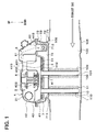
- FIG. 1 is a schematic section view to show a sectional construction of an exhaust heat recovery device according to a first embodiment
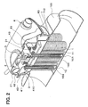
- FIG. 2 is an exploded perspective view to show the exhaust heat recovery device according to the first embodiment
- FIG. 3 is a section view to show a state in which a valve 5 in the first embodiment is closed;
- FIG. 4 is a section view to show a state in which the valve 5 in the first embodiment is opened;
- FIG. 5 is a section view taken on a line V-V in FIG. 3 ;
- FIG. 6 is a section view to show a vicinity of a portion in which a tube 10 is fixed in a core plate in a second embodiment
- FIG. 7 is a section view to show a vicinity of a portion in which a tube 10 is fixed in a core plate in a third embodiment
- FIG. 8 is a schematic section view to show a sectional construction of an exhaust heat recovery device according to a fourth embodiment
- FIG. 9 is a side view to show a tube 10 in a fifth embodiment
- FIG. 10 is a side view to show a tube 10 in a sixth embodiment
- FIG. 11 is a side view to show a tube 10 in a seventh embodiment
- FIG. 12 is a characteristic diagram to show a relationship between the enclosed amount of a working fluid in an eighth embodiment
- FIG. 13 is a characteristic diagram to show a relationship between the enclosed amount of the working fluid and a maximum value of an internal pressure in an eighth embodiment
- FIG. 14 is a characteristic diagram to show a relationship between a boiling performance of a heating part and an upper limit value of the enclosed amount of the working fluid in the eighth embodiment
- FIG. 15 is a perspective view to show a cooling water pipe in a ninth embodiment
- FIG. 16 is a characteristic diagram to show a relationship between a pitch of a groove part and a heat transfer coefficient in the ninth embodiment
- FIG. 17 is a characteristic diagram to show a relationship between the pitch of the groove part and a water flow resistance in the ninth embodiment
- FIG. 18 is a characteristic diagram to show a relationship between a depth of the groove part and a heat transfer coefficient in the ninth embodiment.
- FIG. 19 is a characteristic diagram to show a relationship between the depth of the groove part and the water flow resistance in the ninth embodiment.
- An exhaust heat recovery device of the present embodiment recovers an exhaust heat of an exhaust gas from an exhaust system of an engine (internal combustion engine) of a vehicle and uses the exhaust heat for warming up the engine.
- the direction of an arrow directed up and down in FIG. 1 shows a direction of the state in which the exhaust heat recovery device is mounted in the vehicle.
- FIG. 2 for the purpose of making the figure clear, a part of a hydrogen removing device to be described later will be omitted.
- the exhaust heat recovery device of the present embodiment is provided with a heating part 1 , a condensing part 2 , and a storing part 3 .
- the heating part 1 is provided in an exhaust passage 100 in which the exhaust gas of the engine flows. Further, the heating part 1 exchanges heat between a working fluid enclosed in the heating part 1 and the exhaust gas to thereby evaporate the working fluid.
- the exhaust gas corresponds to a heating fluid of the preset disclosure.
- the condensing part 2 is provided on the outside of the exhaust passage 100 .
- the condensing part 2 exchanges heat between the working fluid evaporated by the heating part 1 and the cooling water of the engine to thereby condense the working fluid.
- the cooling water corresponds to a heated fluid of the present disclosure.
- the storing part 3 is provided on the upper side in a vertical direction of the heating part and on the outside of the exhaust passage 100 .
- the storing part 3 stores the working fluid condensed by the condensing part 2 and the working fluid condensed by the condensing part 2 flows into the heating part 1 through the storing part 3 .
- the heating part 1 , the storing part 3 , and the condensing part 2 are arranged in this order toward an upper side in the vertical direction.
- the heating part 1 has a plurality of tubes 10 in which the working fluid flows and which have their upper end portions in the vertical direction opened and which have their lower end portions in the vertical direction closed.
- a most portion on the lower side in the present embodiment, a portion of approximately 80% from a lower end portion thereof is arranged in the exhaust passage 100 and a portion on the upper side (in the present embodiment, a portion of approximately 20% from an upper end portion thereof) is arranged on the outside of the exhaust passage 100 .
- an exhaust duct 105 forming the exhaust passage 100 has a through hole 106 formed in an upper face thereof and the tubes 10 are inserted into the exhaust passage 100 from an upper side of the through hole 106 , whereby the tubes 10 are arranged in the exhaust passage 100 .
- the upper end portions of the plurality of tubes 10 are joined to a core plate 41 of the storing part 3 to be described later, respectively.
- the plurality of tubes 10 are not connected to each other except for the portions in which the tubes 10 are joined to the core plate 41 .
- each of the tubes 10 is formed in the shape of a hollow cylinder having a closed end and has a bottom portion 101 arranged on the lower side. Further, a corner portion formed by the bottom portion 101 and a side portion 102 of the tube 10 is formed in the shape of a circular arc protruding to the outside of the tube 10 . In other words, the corner portion formed by the bottom portion 101 and the side portion 102 of the tube 10 are chamfered in the shape of the circular arc. Further, a wick 103 made of a metal mesh is provided on an inner surface of the tube 10 . The wick 103 is formed in the shape of a net and is arranged on the entire circumference of the inner surface of the tube 10 .
- the side portion 102 of a portion arranged in the exhaust passage 100 in the tube 10 has a plurality of fins 11 joined thereto, the plurality of fins 11 accelerating a heat conduction between the exhaust gas and the working fluid.
- the fins 11 jointed to the plurality of tubes 10 are not connected to each other.
- each of the fins 11 is formed in the shape of an umbrella. That is, each of the fins 11 has a curved surface 110 shaped like a circular arc in which a portion closer to the lower side is longer in distance from the tube 10 and in which is protruded to the lower side.
- the fin 11 is viewed from a longitudinal direction of the tube 10 (in the vertical direction), the fin is formed in the shape of a ring.
- the tank part 4 On the upper side of the heating part 1 , there is provided a tank part 4 in which the working fluid flows.
- the tank part 4 has the core plate 41 as a tube joint part which has an upper end side of the tube 10 joined thereto, a tank main body part 42 which constructs a tank interior space together with the core plate 41 , and a partition plate 43 which is provided between the core plate 41 and the tank main body part 42 and which partitions the tank interior space into two portions in the vertical direction.
- a space formed by the core plate 41 and the partition plate 43 constructs the storing part 3 and a space formed by the tank main body part 42 and the partition plate 43 constructs the condensing part 2 .
- the core plate 41 has a tube joint face 410 formed in the shape of a flat plane.
- Tube joint face 410 has a plurality of communication holes 411 each of which has each of the tubes 10 inserted thereinto.
- Each of the communication holes 411 of the core plate 41 has a rib 412 formed at the opening edge portion thereof, the rib 412 protruding to the upper side from the tube joint face 410 .
- the rib 412 is formed when the communication hole 411 is formed in the core plate 41 by burring.
- An upper end portion of the tube 10 is arranged on the upper side than the tube joint face 410 , that is, a lower end face in the vertical direction of the core plate 41 . For this reason, the core plate 41 can store the condensed working fluid on the tube joint face 410 thereof.
- the storing part 3 is provided with a wick 31 as a condensed liquid holding part for holding the condensed working fluid by a capillary force.
- the wick 31 is a part which is made of a metal mesh and which can temporarily hold the condensed working fluid in its apertures.
- the condensing part 2 is arranged a cooling water pipe 21 in which the cooling water of the engine flows.
- the condensing part 2 is constructed in such a way that heat is exchanged between the cooling water flowing in the cooling water pipe 21 and the working fluid flowing outside the cooling water pipe 21 .
- the working fluid which is cooled and condensed at the surface of the cooling water pipe 21 is made to drop to the lower side of the condensing part 2 .
- the partition plate 43 of the tank part 4 has a first through hole 431 and a second through hole 432 formed therein, each of the first through hole 431 and the second through hole 432 being formed in a circular shape.
- the storing part 3 and the condensing part 2 communicate with each other via the two through holes 431 , 432 .
- On an outer circumferential edge portion of the first through hole 431 is provided a wall part 433 extending to an upper side in the vertical direction.
- the wall part 433 can make the working fluid (water vapor), which flows out of the storing part 3 and is in the state of gas, flow into the condensing part 2 from the upper side in the vertical direction of the condensing part 2 .
- the second through hole 432 is provided with a valve 5 which opens or closes a passage of the working fluid flowing into the storing part 3 from the condensing part 2 .
- the valve 5 has a cylindrical base part 51 which is fitted in the second through hole 432 .
- the base part 51 has flanges 511 , 512 provided at a lower side end portion and an upper side end portion in the vertical direction thereof.
- An upper side face of the flange 511 on the lower end side of the base part 51 is joined to a face on the lower side of the partition plate 43 .
- a clearance is formed between the flange 512 on the upper end side of the base part 51 and the partition plate 43 , so the flange 512 is not in contact with the partition plate 43 .
- a working fluid passage 513 which makes the condensing part 2 communicate with the storing part 3 .
- the working fluid passage 513 is open at both of a portion, which is between the flange 512 and the partition plate 43 on the side face of the base part 51 , and a face on the lower side of the base part 51 .
- a through hole 514 through which a bar-shaped member 52 extending in the vertical direction passes.
- a valve body 53 for opening and closing the working fluid passage 513 .
- the valve body 53 is arranged in such a way as to be put into contact with a lower end face of the base part 51 .
- An upper end side of the bar-shaped member 52 abuts on a diaphragm 54 formed in the shape of a thin film.
- the valve body 53 is pressed in a direction to close the valve 5 (in an upper direction in FIG. 1 ) by the diaphragm 54 .
- the diaphragm 54 is arranged on the upper side of the base part 51 .
- the diaphragm 54 is formed in the shape of a circular disk.
- the diaphragm 54 is arranged in a diaphragm case 55 and partitions a space in the diaphragm case 55 into a first pressure chamber 551 on the upper side and a second pressure chamber 552 on the lower side.
- the diaphragm case 55 is formed of a first diaphragm case 55 a and a second diaphragm case 55 b , each of which is made by pressing a metal plate having a comparatively thin thickness into a predetermined shape.
- the first and second diaphragm cases 55 a , 55 b are crimped with an outer circumferential face of the diaphragm 54 sandwiched between them, thereby being integrated with each other.
- the second diaphragm case 55 b is joined to an upper end of the base part 51 , whereby the entire diaphragm case 55 is integrally combined with the base part 51 .
- the first pressure chamber 551 formed of the diaphragm 54 and the first diaphragm case 55 a is always made to communicate with the atmosphere through a through hole, which is not shown, or is always sealed in vacuum, thereby being always held at a constant pressure, so the interior of the first pressure chamber 551 is held at the same pressure as the atmospheric pressure.
- the second pressure chamber 552 formed of the diaphragm 54 and the second diaphragm case 55 b is always made to communicate with the condensing part 2 through a through hole, which is not shown, so the interior of the second pressure chamber 552 is held at the same pressure as the condensing part 2 .
- the valve body 53 is driven by the displacement of the diaphragm 54 , which is caused by a pressure difference between the first pressure chamber 551 and the second pressure chamber 552 , an opening area of the working fluid passage 513 is changed, that is, the working fluid passage 513 is opened or closed.
- the valve body 53 is pressed onto a lower end face of the base part 51 , which brings about a state where the working fluid passage 513 is closed, that is, a state where the valve 5 is closed.
- the valve body 53 is moved in a direction to separate from the lower end face of the base part 51 , which brings about a state where the working fluid passage 51 is opened, that is, a state where the valve 5 is opened.
- the valve 5 is opened, as shown by large solid arrows in FIG. 4 , the condensed working fluid flows through the working fluid passage 513 from a side face of the base part 51 and flows out to the storing part 3 from the bottom face of the base part 51 .
- a bypass hole (bypass passage) 56 for making an upper end side of the base part 51 communicate with a lower end side of the base part 51 .
- the flange 512 is provided on the upper end portion of the base part 51 , in the case where the water level of the condensed working fluid is not higher than the upper face of the flange 512 , it is possible to restrict the working fluid from flowing into the bypass hole 56 by vibration.
- a bar-shaped mesh 57 is inserted into the bypass hole 56 . In this way, the flow rate of the working fluid flowing through the bypass hole 56 can be stabilized. Then, by adjusting the dimensions of the mesh 57 , a desired flow rate of working fluid can be acquired.
- the exhaust heat recovery device is provided with a hydrogen removing device 6 for removing the hydrogen gas generated at the high temperature.
- the hydrogen removing device 6 is connected to an upper end portion of the tank part 4 and is constructed in such a way that the hydrogen gas flows in from the upper end portion of the condensing part 2 .
- a partition wall part 61 extending to an upper side from an upper face of the partition plate 43 .
- a clearance is formed between an upper end portion of the partition wall part 61 and the tank main body 42 .
- the valve 5 , the first through hole 431 , the partition wall part 61 are arranged in this order.
- a hydrogen gas introduction passage 62 in which the hydrogen gas generated at the high temperature flows.
- a through hole 413 In a portion corresponding to the hydrogen gas introduction passage 62 in the core plate 41 is formed a through hole 413 .
- a copper oxide receiving part 63 To the through hole 413 is joined an upper end portion of a copper oxide receiving part 63 which is formed in the shape of a cylinder which is open only at an upper end thereof.
- granular copper oxide (II) In the copper oxide receiving part 63 is received granular copper oxide (II).
- the metal oxide receiving part 63 communicates with the condensing part 2 through the hydrogen gas introduction passage 62 .
- the hydrogen reacts with the copper oxide (II) to generate copper and water, so the hydrogen can be removed.
- the exhaust heat recovery device is provided with a heat guard 7 as a heat conduction limiting member for limiting a heat conduction from the exhaust gas flowing through the exhaust passage 100 of the heating part 1 to the working fluid stored in the storing part 3 .
- the heat guard 7 is arranged between the heating part 1 and the storing part 3 .
- a section when the heat guard 7 is viewed from a direction orthogonal to the vertical direction is formed nearly in the shape of a letter C which is open on the upper side. That is, the heat guard 7 is constructed of a bottom part 71 formed in a flat plane perpendicular to the vertical direction, a wall part 72 bent in nearly perpendicularly from the outer circumferential portion of the bottom part 71 and extended to the upper side, and a flange part 73 bent nearly perpendicularly from the wall part 72 and extended in a direction perpendicular to the vertical direction.
- the flange part 73 of the heat guard 7 is joined to the outer circumferential edge portion of the core plate 41 .
- the heat guard 7 is in contact with the core plate 41 only at the flange part 73 and a space (hereinafter also referred to as a heat guard space 74 ) is formed among the bottom part 71 and the core plate 41 and the core plate 41 .
- tube through holes 711 into which the tubes 10 are inserted respectively.
- An inside diameter of the tube through hole 711 is formed in a slightly larger size than an outer diameter of the tube 10 . For this reason, the tube 10 is not in contact with the tube through hole 711 in the state where the tube 10 is inserted into the tube through hole 711 .
- the bottom part 71 of the heat guard 7 is formed in a shape corresponding to the through hole 106 of the exhaust duct 105 , that is, in a shape capable of closing the through hole 106 .
- the heat guard 7 is joined to the exhaust duct 105 in the state where the bottom part 71 closes the through hole 106 of the exhaust duct 105 .
- the exhaust passage 100 is formed of the exhaust duct 105 and the bottom part 71 of the heat guard 7 .
- a heating through hole 712 is formed at a portion opposite to the copper oxide receiving part 63 in the bottom part 71 of the heat guard 7 .
- the exhaust gas flowing through the exhaust passage 100 flows into the heat guard space 74 through the heating through hole 712 .
- the copper oxide receiving part 63 can be heated by the heat acquired by the exhaust gas.
- the exhaust gas flowing through the exhaust passage 100 flows into the heat guard space 74 also from the tube through hole 711 .
- the heat guard 7 is provided with the heating through hole 712 and the tube through hole 711 , the exhaust gas flows not only through the exhaust passage 100 but also through the heat guard space 74 .
- the exhaust passage 100 and the heat guard space 74 correspond to a heating fluid passage of the present disclosure.
- the valve 5 is opened.
- the working fluid is heated by the exhaust gas and hence is evaporated, thereby flowing out to the storing part 3 from the top end portion of the tube 10 .
- the vapor of the working fluid flowing out of the top end portion of the tube 10 flows into the condensing part 2 through the storing part 3 and the first through hole 431 of the partition plate 43 .
- the vapor of the working fluid flowing into the condensing part 2 exchanges heat with the cooling water flowing in the cooling water pipe 21 and hence is condensed on the surface of the cooling water pipe 21 , thereby being brought into liquid and dropped on the partition plate 43 .
- the liquid working fluid dropped on the partition plate 43 flows through the working fluid passage 513 in the valve 5 and is returned onto the core plate 41 of the storing part 3 .
- the liquid working fluid flowing into the storing part 3 is stored on the core plate 41 . Then, when the water level of the working fluid becomes higher than the top end portion of the rib 412 , the working fluid again flows into the tube 10 from the top end portion of the tube 10 .
- the valve 5 is closed. At this time, the working fluid condensed on the surface of the cooling water pipe 21 remains on the partition plate 43 . Then, when the water level of the working fluid remaining on the partition plate 43 becomes higher than the upper face of the flange 512 , the working fluid flows into the storing part 3 through the bypass hole 56 .
- the tube 10 is not constrained at a portion other than the upper side end portion thereof. In this way, it is possible to restrict a portion in which the tube 10 is rooted in the core plate 41 from being broken by a thermal strain developed by a difference in linear expansion caused by a rapid temperature change in the exhaust gas.
- the upper end portion of the tube 10 is arranged on the upper side than the tube joint face 410 of the core plate 41 and there is provided the storing part 3 for storing the working fluid condensed in the condensing part 2 , so a specified amount of liquid working fluid can be made to exist on the tube joint face 410 of the core plate 41 . In this way, the condensed working fluid can be brought into contact with the core plate 41 to thereby restrict a temperature increase in the core plate 41 . Still further, since the exhaust heat recovery device is provided the storing part 3 , when the exhaust heat recovery device usually recovers the exhaust heat, the exhaust heat recovery device can distribute the working fluid uniformly to the respective tubes 10 irrespective of the position in which the valve 5 is provided.
- the wick 31 which holds the working fluid condensed in the condensing part 2 by the capillary force is arranged in the storing part 3 , the liquid working fluid can be wetly spread on the entire surface of the core plate 41 .
- a temperature increase in the core plate 41 can be restricted, which hence makes it possible to restrict a thermal strain from being developed and to reliably restrict the portion in which the tube 10 is fixed to the core plate 41 from being broken by the thermal strain.
- the wick 31 can restrict the liquid working fluid existing on the core plate 41 from being moved to one side or jumped by vibration or by the inclination of the exhaust heat recovery device to thereby make the working fluid flow into the tube 10 in the state where the specified amount of working fluid does not exist on the core plate 41 .
- the valve 5 when load is high and a cooling water temperature is high, the valve 5 needs to be throttled to reduce the flow rate of the working fluid circulated in the exhaust heat recovery device, thereby reducing the amount of heat to be recovered.
- the cooling water temperature when the cooling water temperature is high, the amount of circulation of the working fluid might be excessively reduced by the valve 5 to thereby eliminate the working fluid from being on a part of the core plate 41 (to thereby dry out the core plate 41 ).
- a local temperature distribution will be formed on the core plate 41 and a strained amplitude, which is caused by a temperature difference between at the time when the core plate 41 is dried out and at the time when the water level of the working fluid is high, will extremely reduce the life of the exhaust heat recovery device.
- the bypass hole 56 which makes the working fluid condensed in the condensing part 2 bypass the valve 5 to thereby introduce the working fluid into the storing part 3 .
- the working fluid can be returned to the storing part 3 through the bypass hole 56 .
- the heat guard 7 for restricting the heat conduction from the exhaust gas of the heating part 1 to the working fluid in the storing part 3 is provided between the heating part 1 and the storing part 3 . In this way, it is possible to restrict the core plate 41 from being heated with the heat acquired by the exhaust gas to thereby increase the temperature of the core plate 41 .
- the fins 11 provided on the plurality of tubes 10 are constructed in such a way as not to be connected to each other. In this way, it is possible to restrict the tubes 10 from being constrained at a portion other than the upper side end portion thereof and hence to restrict a thermal strain from being developed by a difference in linear expansion caused by a rapid temperature change in the exhaust gas.
- the fins 11 joined to the tube 10 are pulled inside (to the side of the tube 10 ) and hence the fins are deformed.
- the fins 11 are once deformed, even if the temperature of the tube 10 is made higher, the deformed fins 11 cannot be returned to their original shapes.
- each of the fins 11 has a curved face 110 which is protruded to the lower side and which is shaped like a circular arc.
- the curved face 110 shaped like the circular arc can absorb the deformation of the fun 11 and hence can restrict the fin 11 from being deformed.
- the tube 10 is formed in the shape of a hollow cylinder having a closed end and a corner portion formed of the side part 102 and the bottom part 101 is formed in the shape a circular arc. In this way, it is possible to secure the pressure resistance of the tube 10 and to restrict the thermal strain from being developed in the tube 10 .
- the exhaust heat recovery device provided with the hydrogen removing device 6 for removing the hydrogen gas generated at the high temperature has the copper oxide receiving part 63 in which copper oxide (II) for removing the hydrogen is enclosed. Since a hydrogen removing reaction by the copper oxide (II) (see the chemical formula 2 described above) is not caused at a high temperature not less than 300° C., the copper oxide receiving part 63 is usually arranged in the heating part 1 in which the exhaust gas flows. However, under the circumstance of a high temperature not less than 600° C., an oxidation phenomenon of the stainless steel is accelerated with the copper oxide (II) as a medium, which hence presents a problem that the tube 10 of the heating part 1 is oxidized and corroded.
- the upper end portion of the copper oxide receiving part 63 is connected to the core plate 41 and the copper oxide receiving part 63 is arranged in the heat guard space 74 in which the exhaust gas flows. According to this, since the copper oxide receiving part 63 is arranged at the portion in which the exhaust gas flows, the copper oxide receiving part 63 can be heated with the heat acquired by the exhaust gas and hence the hydrogen removing reaction by the copper oxide (II) can be reliably caused.
- the upper end portion of the copper oxide receiving part 63 is connected to the core plate 41 which has the liquid working fluid stored on the upper face thereof and which is at a comparatively low temperature, so the copper oxide receiving part 63 can be restricted from being brought to an abnormally high temperature. Hence, it is possible to remove the hydrogen gas and to restrict the abnormal oxidization phenomenon of the stainless steel at the same time.
- the copper oxide receiving part 63 is arranged in the heat guard space 74 and the heating through hole 712 is formed in the heat guard space 74 to thereby introduce the exhaust gas into the heat guard space 74 , so it is possible to prevent the main stream of the exhaust gas of high temperature from directly hitting the copper oxide receiving part 63 . In this way, it is possible to restrict the temperature of the copper oxide receiving part 63 from being changed by the flow rate of the exhaust gas. Hence, even when the exhaust heat recovery device is mounted in a vehicle having a large displacement, it is possible to remove the hydrogen gas and to restrict the abnormal oxidization phenomenon of the stainless steel at the same time.
- the present embodiment is constructed in such a way that the hydrogen gas introduction passage 62 is connected to the upper side of the condensing part 2 to thereby make the hydrogen gas flow into the hydrogen gas removing device 6 from the upper end portion of the condensing part 2 .
- the hydrogen gas introduction passage 62 is connected to the upper side of the condensing part 2 to thereby make the hydrogen gas flow into the hydrogen gas removing device 6 from the upper end portion of the condensing part 2 .
- the upper end portion of the tube 10 is arranged on the upper side of the core plate 41 .
- the communication hole 411 of the core plate 41 has a rib 414 formed on an opening edge portion thereof, the rib 414 protruding to a lower side in the vertical direction.
- the rib 414 is formed at the time when the communication hole 411 is formed in the core plate 41 by burring.
- the tube 10 has a wick 104 provided on an upper end face thereof, the wick 104 being made of metal in such a way as to connect a wick 103 arranged on an inner face of the tube 10 and a wick 31 arranged on the core plate 41 .
- the wick 104 is provided on the upper end portion of the tube 10 , so when the exhaust heat recovery device usually recovers the exhaust heat, the exhaust heat recovery device can suck only the working fluid overflowing from the wick 31 into the tube 10 by the wick 104 . Hence, it is possible to restrict the exhaust heat recovery device from making the working fluid flow into the tube 10 more than necessary to thereby eliminate the working fluid on the core plate 41 (to thereby dry out the core plate 41 ).
- the third embodiment is different from the second embodiment described above in the shape of the upper end portion of the tube 10 .
- the upper end portion of the tube 10 is formed in a reverse flow restricting portion 107 which is curved in the shape of a circular arc in such a way as to expand to the inside of the tube 10 . Since the reverse flow restricting portion 107 is provided, in the case where the exhaust heat is not recovered, the reverse flow restricting portion 107 can restrict the condensed working fluid stored in the storing part 3 from flowing into the tube 10 by the acceleration of the vehicle or the like.
- the fourth embodiment is different from the first embodiment described above in that the hydrogen removing device 6 is constructed as a part separate from the tank part 4 .
- the fins 11 will be omitted in FIG. 8 .
- the copper oxide receiving part 63 of the hydrogen removing device 6 is arranged on the outside of the exhaust duct 105 (on the side of the outside air). Further, one face of the copper oxide receiving part 63 is joined to an outer surface of the exhaust duct 105 . In this way, a part of the copper oxide receiving part 63 is joined to the exhaust passage 100 via the exhaust duct 105 . Further, of the copper oxide receiving part 63 , a portion which is not in contact with the outer surface of the exhaust duct 105 is in contact with the outside air.
- a hydrogen gas introduction pipe 64 which forms the hydrogen gas introduction passage 62 .
- the other end portion of the hydrogen gas introduction pipe 64 is connected to the condensing part 2 of the tank part 4 .
- the copper oxide receiving part 63 and the condensing part 2 are connected to each other via the hydrogen gas introduction pipe 64 . In this way, the hydrogen gas which flows out of the condensing part 2 flows through the hydrogen gas introduction pipe 64 and flows into the copper oxide receiving part 63 .
- the copper oxide receiving part 63 is arranged at a portion in contact with the exhaust passage 100 in which the exhaust gas flows, so the copper oxide receiving part 63 can be heated with the heat acquired by the exhaust gas and hence the hydrogen removing reaction by the copper oxide (II) can be reliably caused.
- a portion which is not in contact with the exhaust passage 100 in the copper oxide receiving part 63 is brought into contact with the outside air, so the copper oxide receiving part 63 can be restricted from being made abnormally high temperature. Hence, it is possible to remove the hydrogen gas and to restrict the abnormal oxidization phenomenon of the stainless steel at the same time.
- the fifth embodiment is different from the first embodiment described above in the construction of the fin 11 .
- the fins 11 of the present embodiment are formed by plastically working an outside surface of the tube 10 in a spiral shape. According to this, it is possible to eliminate the need for providing separate members as fins, so the fins 11 can be provided on the outside surface of the tube 10 with the number of parts reduced. Further, the fins are formed in the spiral shape, so the fins can improve a heat transfer coefficient.
- the sixth embodiment is different from the first embodiment described above in the construction of the fin 11 .
- the fins 11 of the present embodiment are formed by knurling the outside surface of the tube 10 . According to this, it is possible to eliminate the need for providing separate members as fins, so the fins 11 can be provided on the outside surface of the tube 10 with the number of parts reduced. Further, the fins 11 are formed by knurling, so the fins can improve the heat transfer coefficient.
- the seventh embodiment is different from the first embodiment described above in the construction of the tube 10 and the fin 11 .
- the tube 10 of the present embodiment has a spiral groove part 108 formed on the inside surface thereof.
- the groove part 108 functions as a wick for sucking the liquid working fluid stored in the storing part 3 by a capillary force and for supplying the liquid working fluid to the tube 10 .
- the present embodiment without providing a wick which is a part separate from the tube 10 , it is possible to suck the liquid working fluid stored in the storing part 3 by the capillary force and to supply the liquid working fluid to the tube 10 . For this reason, it is possible to reliably supply the working fluid to the tube 10 from the storing part 3 with the number of parts reduced.
- the eighth embodiment is different from the first embodiment described above in that the amount of working fluid (volume of working fluid) enclosed in the exhaust heat recovery device is specified.
- the valve 5 of the present embodiment is constructed in such a way that when the temperature of the working fluid flowing through the working fluid passage 513 which makes the condensing part 2 communicate with the storing part 3 becomes not less than a predetermined standard temperature, the condensed working fluid passage 513 is closed.
- a mechanically operated valve which senses the pressure of the working fluid enclosed therein to thereby operate the diaphragm 54 can be employed as the valve 5 .
- the relationship between the temperature and the pressure of the working fluid is always 1 to 1, so when the pressure of the working fluid is sensed, the temperature of the working fluid can be indirectly sensed.
- a working fluid temperature response valve constructed of a mechanical mechanism in which a valve body 53 is displaced by a thermo-wax (temperature sensing member) whose volume is changed by the temperature to thereby open or close the working fluid passage 513 .
- a heating-part heat transfer area that is the total sum of heat transfer areas between the exhaust gas and the working fluid in the heating part 1 is F g
- a heating-part volume that is the total sum of the volumes of parts in which the working fluid flows (total sum of the volumes of the plurality of tubes 10 ) in the heating part 1 is V g
- a heat transfer coefficient of the exhaust gas is ⁇ g
- a condensing-part heat transfer area that is the total sum of heat transfer areas between the cooling water and the working fluid in the condensing part 2 is F w
- a condensing-part volume that is the volume of a part in which the working fluid flows in the condensing part 2 is V w
- a heat transfer coefficient of the cooling water is ⁇ w
- the volume of the storing part 3 is V c .
- the lower limit value M 1 of the enclosed amount of the working fluid is set in such a way as to satisfy the relationship shown by the following mathematical formula 1.
- M 1 V w +0.4 V g (Mathematical formula 1)
- the exhaust heat recovery device of the present embodiment is constructed of stainless steel.
- the pressure resistant strength of the stainless steel is approximately 500 kPa, so a working fluid volume M 2 in which the maximum value Pr_max of the internal pressure becomes 500 kPa was found in each of the exhaust heat recovery devices. If a working fluid amount enclosed in each of the exhaust heat recovery devices is not more than M 2 , the internal pressure of the exhaust heat recovery device is not more than 500 kPa.
- an upper limit value M 2 of the enclosed amount of the working fluid is set in such a way as to satisfy the relationship shown by the following mathematical formula 2.
- M 2 V w /2+ V c +150exp( ⁇ 11 ⁇ g F g / ⁇ w F w ) (Mathematical formula 2)
- an upper limit value M 2 of the volume of the working fluid enclosed in the exhaust heat recovery device is set in such a way as to satisfy the relationship shown by the mathematical formula 2 described above, even if the vehicle is brought into any state (is accelerated or changed in speed), a maximum value of variation in the internal pressure can be control to a value not more than 500 kPa. Hence, the pressure resistance of the exhaust heat recovery device can be secured.
- the enclosed amount of the working fluid specified in the present embodiment is determined so as to restrict the internal pressure from being abnormally increased.
- the mechanically operated valve which senses the pressure of the working fluid enclosed therein to thereby operate the diaphragm 54 can be employed as the valve 5 in terms of response.
- the ninth embodiment is different from the first embodiment described above in the shape of the cooling water pipe 21 .
- the cooling water pipe 21 of the present embodiment has a spiral groove part 21 a formed on the surface thereof.
- the groove part 21 a is formed on a portion other than a bent portion 21 b in which a cooling water passage is bent in the cooling water pipe 21 .
- a pipe having an outer diameter of 10 mm or more to 30 mm or less is used as the cooling water pipe 21 .
- the condensing performance can be improved without increasing a space in which the cooling water pipe 21 is mounted.
- a heat transfer coefficient ⁇ in the cooling water pipe 21 can be made larger than 200 W/m 2 K, so the heat transfer coefficient ⁇ can be improved.
- the water flow resistance of the cooling water pipe 21 can be made 300 or less, that is, the water flow resistance of the cooling water pipe 21 can be reduced.
- the spiral pitch of the groove part 21 a is set at 2 mm or more to 18 mm or less, the heat transfer coefficient ⁇ in the cooling water pipe 21 can be improved and the water flow resistance of the cooling pipe 21 can be reduced. In this way, the performance of the condensing part 2 can be reliably improved.
- the heat transfer coefficient ⁇ in the cooling water pipe 21 can be made larger than 200 W/m 2 K and hence the heat transfer coefficient ⁇ can be improved.
- the water flow resistance of the cooing water pipe 21 becomes larger.
- the depth of the groove part 21 a is set at 2.9 mm or less, the water flow resistance of the cooing water pipe 21 can be made 300 or less, so the water flow resistance of the cooing water pipe 21 can be reduced.
- the depth of the groove part 21 a is set at 2.0 mm or more to 2.9 mm or less, the heat transfer coefficient ⁇ in the cooling water pipe 21 can be improved and the water flow resistance of the cooing water pipe 21 can be reduced. In this way, the performance of the condensing part 2 can be surely improved.
- the exhaust heat recovery device is constructed of the chrome-based stainless steel, but a material constructing the exhaust heat recovery device is not limited to the this.
- the exhaust heat recovery device may be constructed of the material if there is any other material which reacts with the water of the working fluid to thereby generate hydrogen when it is heated.
- the hydrogen removing device 6 is formed integrally with the tank part 4 , that is, the partition wall part 61 is provided in the tank part 4 to thereby form the hydrogen gas introduction passage 62 .
- the hydrogen removing device 6 may be constructed as a part separate from the tank part 4 to thereby introduce the hydrogen gas from the upper end portion of the condensing part 2 of the tank part 4 .
- the tube 10 is formed in the shape of the hollow cylinder having the closed end and in which the corner portion formed of the bottom portion 101 and the side face portion 102 of the tube 10 is formed in the shape of the circular arc protruding to the outside of the tube 10 .
- the shape of the tube 10 is not limited to this.
- the corner portion formed of the bottom portion 101 and the side face portion 102 of the tube 10 may be formed in a right angle or the tube 10 may be formed in the other shape of such as a hollow ellipsoidal cylinder having a closed end.
- the fin 11 is formed in the shape of the umbrella.
- the fin 11 may be formed in the shape of a flat plate.
- wick 103 is arranged in the tube 10 .
- the wick 103 does not need to be arranged in the tube 10 .
- a wick made of a metal mesh may be arranged on the upper end portion of the tube 10 in such a way as to connect the wick 103 in the tube 10 to the wick 31 on the core plate 41 .
- valve 5 is not limited to this but, for example, an electromagnetic valve whose operation is controlled on the basis of a control voltage outputted from a control device may be employed as the valve 5 .
- the exhaust heat recovery device is provided with a temperature sensor for sensing the temperature of the working fluid. Then, the control device controls the operation of the electromagnetic valve on the basis of the temperature of the working fluid sensed by the temperature sensor.
Landscapes
- Engineering & Computer Science (AREA)
- Chemical & Material Sciences (AREA)
- Combustion & Propulsion (AREA)
- Mechanical Engineering (AREA)
- General Engineering & Computer Science (AREA)
- Heat-Exchange Devices With Radiators And Conduit Assemblies (AREA)
Abstract
Description
2Fe+2Cr+3H2O→Fe2O3+Cr2O3+3H2 (Chemical formula 1)
3CuO+3H2→3Cu+3H2O (Chemical formula 2)
M 1 =V w+0.4V g (Mathematical formula 1)
M 2 =V w/2+V c+150exp(−11×αg F g/αw F w)
M 2 =V w/2+V c+150exp(−11×αg F g/αw F w) (Mathematical formula 2)
Claims (20)
M 1 =V w+0.4V g; (first mathematical formula)
and
M 2 =V w/2+V c+150exp(−11×αg F g/αw F w), (second mathematical formula)
Applications Claiming Priority (5)
| Application Number | Priority Date | Filing Date | Title |
|---|---|---|---|
| JP2012175156 | 2012-08-07 | ||
| JP2012-175156 | 2012-08-07 | ||
| JP2013068046A JP6044419B2 (en) | 2012-08-07 | 2013-03-28 | Waste heat recovery device |
| JP2013-068046 | 2013-03-28 | ||
| PCT/JP2013/004662 WO2014024437A1 (en) | 2012-08-07 | 2013-08-01 | Exhaust heat recovery device |
Publications (2)
| Publication Number | Publication Date |
|---|---|
| US20150226154A1 US20150226154A1 (en) | 2015-08-13 |
| US9458792B2 true US9458792B2 (en) | 2016-10-04 |
Family
ID=50067692
Family Applications (1)
| Application Number | Title | Priority Date | Filing Date |
|---|---|---|---|
| US14/420,296 Expired - Fee Related US9458792B2 (en) | 2012-08-07 | 2013-08-01 | Exhaust heat recovery device |
Country Status (5)
| Country | Link |
|---|---|
| US (1) | US9458792B2 (en) |
| JP (1) | JP6044419B2 (en) |
| CN (1) | CN104541045B (en) |
| DE (1) | DE112013003962T5 (en) |
| WO (1) | WO2014024437A1 (en) |
Families Citing this family (2)
| Publication number | Priority date | Publication date | Assignee | Title |
|---|---|---|---|---|
| US11073278B2 (en) * | 2011-10-13 | 2021-07-27 | Tinman Inc | Vaporization apparatus |
| US10428713B2 (en) | 2017-09-07 | 2019-10-01 | Denso International America, Inc. | Systems and methods for exhaust heat recovery and heat storage |
Citations (23)
| Publication number | Priority date | Publication date | Assignee | Title |
|---|---|---|---|---|
| JPS5579992A (en) | 1978-12-11 | 1980-06-16 | Babcock Hitachi Kk | Heat transfer device |
| JPS5585891A (en) | 1978-12-22 | 1980-06-28 | Hitachi Ltd | Gas-to-gas heat exchanger |
| US4489777A (en) * | 1982-01-21 | 1984-12-25 | Del Bagno Anthony C | Heat pipe having multiple integral wick structures |
| US4621681A (en) * | 1977-11-09 | 1986-11-11 | Q-Dot Corporation | Waste heat boiler |
| JPS63247595A (en) | 1987-04-01 | 1988-10-14 | Takuma Sogo Kenkyusho:Kk | Thermosyphon |
| JPH01150413A (en) | 1987-12-09 | 1989-06-13 | Fujikura Ltd | Manufacture of heat pipe |
| US4884628A (en) * | 1988-10-19 | 1989-12-05 | En Jian Chen | Heat pipe employing hydrogen oxidation means |
| US4953632A (en) | 1987-12-09 | 1990-09-04 | Fujikura Ltd. | Heat pipe and method of manufacturing the same |
| JPH0552491A (en) | 1991-08-22 | 1993-03-02 | Mitsubishi Electric Corp | Heat exchanging device |
| JPH07120179A (en) | 1993-10-28 | 1995-05-12 | Calsonic Corp | Heat siphon waste heat recovery apparatus |
| JPH08204075A (en) | 1995-01-27 | 1996-08-09 | Sumitomo Precision Prod Co Ltd | Plate fin type element cooler |
| JPH09152287A (en) | 1995-11-29 | 1997-06-10 | Yazaki Corp | Absorption refrigerator and its heat exchanger |
| JPH11257882A (en) | 1998-03-12 | 1999-09-24 | Sharp Corp | Heat pipe and heat collecting device |
| US20060231235A1 (en) | 2005-04-12 | 2006-10-19 | Denso Corporation | Heat pipe |
| JP2006292337A (en) | 2005-04-14 | 2006-10-26 | Denso Corp | Heat pipe equipment |
| JP2006313056A (en) | 2005-04-05 | 2006-11-16 | Denso Corp | Heat pipe and exhaust heat recovery device using the same |
| JP2007155246A (en) | 2005-12-06 | 2007-06-21 | Denso Corp | Heat pipe equipment |
| JP2007278623A (en) | 2006-04-07 | 2007-10-25 | Denso Corp | Waste heat recovery device |
| JP2007332857A (en) | 2006-06-15 | 2007-12-27 | Denso Corp | Exhaust heat recovery unit |
| JP2008121909A (en) | 2006-11-08 | 2008-05-29 | Iida Sangyo:Kk | Heat pipe |
| US20090014154A1 (en) * | 2005-11-09 | 2009-01-15 | Tir Technology Lp | Passive Thermal Management System |
| JP2011169514A (en) | 2010-02-18 | 2011-09-01 | Toyota Motor Corp | Exhaust heat recovery device |
| JP2012215365A (en) | 2011-04-01 | 2012-11-08 | Yanmar Co Ltd | Heat exchanger |
Family Cites Families (6)
| Publication number | Priority date | Publication date | Assignee | Title |
|---|---|---|---|---|
| JPH037746Y2 (en) * | 1986-07-28 | 1991-02-26 | ||
| JPH0188178U (en) * | 1987-11-30 | 1989-06-09 | ||
| US6055803A (en) * | 1997-12-08 | 2000-05-02 | Combustion Engineering, Inc. | Gas turbine heat recovery steam generator and method of operation |
| JP5307987B2 (en) * | 2006-06-09 | 2013-10-02 | 株式会社デンソー | Waste heat recovery device |
| JP4432979B2 (en) * | 2007-02-08 | 2010-03-17 | 株式会社デンソー | Exhaust heat recovery system |
| JP4259583B2 (en) * | 2007-02-15 | 2009-04-30 | 株式会社デンソー | Exhaust heat recovery device |
-
2013
- 2013-03-28 JP JP2013068046A patent/JP6044419B2/en not_active Expired - Fee Related
- 2013-08-01 US US14/420,296 patent/US9458792B2/en not_active Expired - Fee Related
- 2013-08-01 CN CN201380041651.9A patent/CN104541045B/en not_active Expired - Fee Related
- 2013-08-01 WO PCT/JP2013/004662 patent/WO2014024437A1/en not_active Ceased
- 2013-08-01 DE DE112013003962.1T patent/DE112013003962T5/en not_active Withdrawn
Patent Citations (25)
| Publication number | Priority date | Publication date | Assignee | Title |
|---|---|---|---|---|
| US4621681A (en) * | 1977-11-09 | 1986-11-11 | Q-Dot Corporation | Waste heat boiler |
| JPS5579992A (en) | 1978-12-11 | 1980-06-16 | Babcock Hitachi Kk | Heat transfer device |
| JPS5585891A (en) | 1978-12-22 | 1980-06-28 | Hitachi Ltd | Gas-to-gas heat exchanger |
| US4489777A (en) * | 1982-01-21 | 1984-12-25 | Del Bagno Anthony C | Heat pipe having multiple integral wick structures |
| JPS63247595A (en) | 1987-04-01 | 1988-10-14 | Takuma Sogo Kenkyusho:Kk | Thermosyphon |
| JPH01150413A (en) | 1987-12-09 | 1989-06-13 | Fujikura Ltd | Manufacture of heat pipe |
| US4953632A (en) | 1987-12-09 | 1990-09-04 | Fujikura Ltd. | Heat pipe and method of manufacturing the same |
| US4884628A (en) * | 1988-10-19 | 1989-12-05 | En Jian Chen | Heat pipe employing hydrogen oxidation means |
| JPH0552491A (en) | 1991-08-22 | 1993-03-02 | Mitsubishi Electric Corp | Heat exchanging device |
| JPH07120179A (en) | 1993-10-28 | 1995-05-12 | Calsonic Corp | Heat siphon waste heat recovery apparatus |
| JPH08204075A (en) | 1995-01-27 | 1996-08-09 | Sumitomo Precision Prod Co Ltd | Plate fin type element cooler |
| JPH09152287A (en) | 1995-11-29 | 1997-06-10 | Yazaki Corp | Absorption refrigerator and its heat exchanger |
| JPH11257882A (en) | 1998-03-12 | 1999-09-24 | Sharp Corp | Heat pipe and heat collecting device |
| JP2006313056A (en) | 2005-04-05 | 2006-11-16 | Denso Corp | Heat pipe and exhaust heat recovery device using the same |
| US20060231235A1 (en) | 2005-04-12 | 2006-10-19 | Denso Corporation | Heat pipe |
| JP2006317013A (en) | 2005-04-12 | 2006-11-24 | Denso Corp | Heat pipe and exhaust heat recovery device using the same |
| JP2006292337A (en) | 2005-04-14 | 2006-10-26 | Denso Corp | Heat pipe equipment |
| US20090014154A1 (en) * | 2005-11-09 | 2009-01-15 | Tir Technology Lp | Passive Thermal Management System |
| JP2007155246A (en) | 2005-12-06 | 2007-06-21 | Denso Corp | Heat pipe equipment |
| JP2007278623A (en) | 2006-04-07 | 2007-10-25 | Denso Corp | Waste heat recovery device |
| JP2007332857A (en) | 2006-06-15 | 2007-12-27 | Denso Corp | Exhaust heat recovery unit |
| JP2008121909A (en) | 2006-11-08 | 2008-05-29 | Iida Sangyo:Kk | Heat pipe |
| JP2011169514A (en) | 2010-02-18 | 2011-09-01 | Toyota Motor Corp | Exhaust heat recovery device |
| US20130037235A1 (en) | 2010-02-18 | 2013-02-14 | Motoya Sakabe | Exhaust heat recovery apparatus |
| JP2012215365A (en) | 2011-04-01 | 2012-11-08 | Yanmar Co Ltd | Heat exchanger |
Non-Patent Citations (2)
| Title |
|---|
| International Search Report and Written Opinion (in Japanese with English Translation) for PCT/JP2013/004662, mailed Nov. 5, 2013; ISA/JP. |
| Office Action mailed Aug. 31, 2015 in the corresponding CN application No. 201380041651.9 (in Chinese with English translation). |
Also Published As
| Publication number | Publication date |
|---|---|
| DE112013003962T5 (en) | 2015-04-23 |
| WO2014024437A1 (en) | 2014-02-13 |
| CN104541045B (en) | 2016-06-01 |
| CN104541045A (en) | 2015-04-22 |
| US20150226154A1 (en) | 2015-08-13 |
| JP6044419B2 (en) | 2016-12-14 |
| JP2014051966A (en) | 2014-03-20 |
Similar Documents
| Publication | Publication Date | Title |
|---|---|---|
| CN101356347B (en) | Exhaust heat recovery equipment | |
| US8245491B2 (en) | Heat recovery system and method | |
| CN103069146B (en) | Micro-condensing device and evaporative emission control system with the micro-condensing device | |
| US7877991B2 (en) | Exhaust heat recovery device | |
| US20080011458A1 (en) | Exhaust heat recovery device | |
| EP1801531B1 (en) | Waste heat collecting apparatus | |
| US9458792B2 (en) | Exhaust heat recovery device | |
| US20090000285A1 (en) | Exhaust heat recovery device | |
| US20080196401A1 (en) | Exhaust heat recovery apparatus | |
| JP4849097B2 (en) | Waste heat recovery unit | |
| JP2009074494A (en) | Exhaust heat recovery device | |
| CN100510337C (en) | Waste heat collecting apparatus | |
| JP2006284020A (en) | Heat pipe | |
| JP5077061B2 (en) | Waste heat recovery unit | |
| CN100523471C (en) | Exhaust heat recovery device | |
| JP2008025884A (en) | Boiling cooling heat exchanger | |
| KR100737164B1 (en) | Header of high pressure heat exchanger | |
| JP4682932B2 (en) | Loop heat pipe | |
| JP2009058205A (en) | Exhaust heat recovery device | |
| CN101333976B (en) | Exhaust heat recovery device | |
| JP4785397B2 (en) | Vehicular air conditioner evaporator | |
| KR20200118539A (en) | Tube-pin assembly | |
| JP4779922B2 (en) | Exhaust heat recovery unit | |
| EP3748269A1 (en) | A heat exchanger | |
| KR102200300B1 (en) | A condenser |
Legal Events
| Date | Code | Title | Description |
|---|---|---|---|
| AS | Assignment |
Owner name: DENSO CORPORATION, JAPAN Free format text: ASSIGNMENT OF ASSIGNORS INTEREST;ASSIGNORS:UEDA, KENTA;YAMANAKA, YASUTOSHI;KUNIKATA, YUHEI;AND OTHERS;SIGNING DATES FROM 20150116 TO 20150122;REEL/FRAME:034911/0175 |
|
| FEPP | Fee payment procedure |
Free format text: PAYOR NUMBER ASSIGNED (ORIGINAL EVENT CODE: ASPN); ENTITY STATUS OF PATENT OWNER: LARGE ENTITY |
|
| STCF | Information on status: patent grant |
Free format text: PATENTED CASE |
|
| FEPP | Fee payment procedure |
Free format text: MAINTENANCE FEE REMINDER MAILED (ORIGINAL EVENT CODE: REM.); ENTITY STATUS OF PATENT OWNER: LARGE ENTITY |
|
| LAPS | Lapse for failure to pay maintenance fees |
Free format text: PATENT EXPIRED FOR FAILURE TO PAY MAINTENANCE FEES (ORIGINAL EVENT CODE: EXP.); ENTITY STATUS OF PATENT OWNER: LARGE ENTITY |
|
| STCH | Information on status: patent discontinuation |
Free format text: PATENT EXPIRED DUE TO NONPAYMENT OF MAINTENANCE FEES UNDER 37 CFR 1.362 |
|
| FP | Lapsed due to failure to pay maintenance fee |
Effective date: 20201004 |