US9456544B2 - Precision super seeder - Google Patents
Precision super seeder Download PDFInfo
- Publication number
- US9456544B2 US9456544B2 US14/748,072 US201514748072A US9456544B2 US 9456544 B2 US9456544 B2 US 9456544B2 US 201514748072 A US201514748072 A US 201514748072A US 9456544 B2 US9456544 B2 US 9456544B2
- Authority
- US
- United States
- Prior art keywords
- seed
- seeder
- tray
- frame
- seed box
- Prior art date
- Legal status (The legal status is an assumption and is not a legal conclusion. Google has not performed a legal analysis and makes no representation as to the accuracy of the status listed.)
- Active
Links
- 241000721671 Ludwigia Species 0.000 claims abstract 15
- 241000196324 Embryophyta Species 0.000 claims description 8
- 230000008878 coupling Effects 0.000 claims description 5
- 238000010168 coupling process Methods 0.000 claims description 5
- 238000005859 coupling reaction Methods 0.000 claims description 5
- 238000000034 method Methods 0.000 abstract description 6
- 240000001931 Ludwigia octovalvis Species 0.000 description 91
- 235000021374 legumes Nutrition 0.000 description 33
- 230000007246 mechanism Effects 0.000 description 10
- 239000002689 soil Substances 0.000 description 6
- 230000001419 dependent effect Effects 0.000 description 3
- 238000003971 tillage Methods 0.000 description 3
- 241000219198 Brassica Species 0.000 description 2
- 235000011331 Brassica Nutrition 0.000 description 2
- 241000234642 Festuca Species 0.000 description 2
- 244000068988 Glycine max Species 0.000 description 2
- 235000010469 Glycine max Nutrition 0.000 description 2
- 241000209049 Poa pratensis Species 0.000 description 2
- 230000003750 conditioning effect Effects 0.000 description 2
- 238000005259 measurement Methods 0.000 description 2
- 241001327399 Andropogon gerardii Species 0.000 description 1
- 244000075850 Avena orientalis Species 0.000 description 1
- 235000007319 Avena orientalis Nutrition 0.000 description 1
- 241000047982 Axonopus Species 0.000 description 1
- 241000145727 Bouteloua curtipendula Species 0.000 description 1
- 240000002791 Brassica napus Species 0.000 description 1
- 235000011293 Brassica napus Nutrition 0.000 description 1
- 235000000540 Brassica rapa subsp rapa Nutrition 0.000 description 1
- 244000025254 Cannabis sativa Species 0.000 description 1
- 241000258920 Chilopoda Species 0.000 description 1
- 244000298479 Cichorium intybus Species 0.000 description 1
- 235000007542 Cichorium intybus Nutrition 0.000 description 1
- 240000004585 Dactylis glomerata Species 0.000 description 1
- 240000008620 Fagopyrum esculentum Species 0.000 description 1
- 235000009419 Fagopyrum esculentum Nutrition 0.000 description 1
- 244000020551 Helianthus annuus Species 0.000 description 1
- 235000003222 Helianthus annuus Nutrition 0.000 description 1
- 240000005979 Hordeum vulgare Species 0.000 description 1
- 235000007340 Hordeum vulgare Nutrition 0.000 description 1
- 244000100545 Lolium multiflorum Species 0.000 description 1
- 240000004296 Lolium perenne Species 0.000 description 1
- 240000004658 Medicago sativa Species 0.000 description 1
- 235000017587 Medicago sativa ssp. sativa Nutrition 0.000 description 1
- 244000178706 Ornithopus sativus Species 0.000 description 1
- 241001520808 Panicum virgatum Species 0.000 description 1
- 240000004713 Pisum sativum Species 0.000 description 1
- 235000010582 Pisum sativum Nutrition 0.000 description 1
- 241000209504 Poaceae Species 0.000 description 1
- 244000088415 Raphanus sativus Species 0.000 description 1
- 235000006140 Raphanus sativus var sativus Nutrition 0.000 description 1
- 240000000296 Sabal minor Species 0.000 description 1
- 235000002924 Sabal minor Nutrition 0.000 description 1
- 240000003829 Sorghum propinquum Species 0.000 description 1
- 235000011684 Sorghum saccharatum Nutrition 0.000 description 1
- 241000219793 Trifolium Species 0.000 description 1
- 235000021307 Triticum Nutrition 0.000 description 1
- 244000098338 Triticum aestivum Species 0.000 description 1
- GDTBXPJZTBHREO-UHFFFAOYSA-N bromine Chemical compound BrBr GDTBXPJZTBHREO-UHFFFAOYSA-N 0.000 description 1
- 239000011888 foil Substances 0.000 description 1
- 235000013305 food Nutrition 0.000 description 1
- 230000014509 gene expression Effects 0.000 description 1
- 238000003780 insertion Methods 0.000 description 1
- 230000037431 insertion Effects 0.000 description 1
- 239000002184 metal Substances 0.000 description 1
- 239000000203 mixture Substances 0.000 description 1
- 238000010899 nucleation Methods 0.000 description 1
- 230000007226 seed germination Effects 0.000 description 1
- 239000007787 solid Substances 0.000 description 1
- 230000003068 static effect Effects 0.000 description 1
Images


Classifications
-
- A—HUMAN NECESSITIES
- A01—AGRICULTURE; FORESTRY; ANIMAL HUSBANDRY; HUNTING; TRAPPING; FISHING
- A01C—PLANTING; SOWING; FERTILISING
- A01C7/00—Sowing
- A01C7/008—Sod or grassland seeding
-
- A—HUMAN NECESSITIES
- A01—AGRICULTURE; FORESTRY; ANIMAL HUSBANDRY; HUNTING; TRAPPING; FISHING
- A01B—SOIL WORKING IN AGRICULTURE OR FORESTRY; PARTS, DETAILS, OR ACCESSORIES OF AGRICULTURAL MACHINES OR IMPLEMENTS, IN GENERAL
- A01B49/00—Combined machines
- A01B49/04—Combinations of soil-working tools with non-soil-working tools, e.g. planting tools
- A01B49/06—Combinations of soil-working tools with non-soil-working tools, e.g. planting tools for sowing or fertilising
-
- A—HUMAN NECESSITIES
- A01—AGRICULTURE; FORESTRY; ANIMAL HUSBANDRY; HUNTING; TRAPPING; FISHING
- A01C—PLANTING; SOWING; FERTILISING
- A01C7/00—Sowing
- A01C7/002—Dibble seeders
-
- A—HUMAN NECESSITIES
- A01—AGRICULTURE; FORESTRY; ANIMAL HUSBANDRY; HUNTING; TRAPPING; FISHING
- A01C—PLANTING; SOWING; FERTILISING
- A01C7/00—Sowing
- A01C7/18—Machines for depositing quantities of seed at intervals
-
- A—HUMAN NECESSITIES
- A01—AGRICULTURE; FORESTRY; ANIMAL HUSBANDRY; HUNTING; TRAPPING; FISHING
- A01C—PLANTING; SOWING; FERTILISING
- A01C7/00—Sowing
- A01C7/20—Parts of seeders for conducting and depositing seed
- A01C7/208—Chassis; Coupling means to a tractor or the like; Lifting means; Side markers
-
- A—HUMAN NECESSITIES
- A01—AGRICULTURE; FORESTRY; ANIMAL HUSBANDRY; HUNTING; TRAPPING; FISHING
- A01C—PLANTING; SOWING; FERTILISING
- A01C7/00—Sowing
- A01C7/08—Broadcast seeders; Seeders depositing seeds in rows
- A01C7/10—Devices for adjusting the seed-box ; Regulation of machines for depositing quantities at intervals
- A01C7/107—Calibration of the seed rate
Definitions
- Embodiments relate to a seeder configured to condition and seed ground using a variety of seeds and different tools.
- Seeders may be used in a variety of agricultural applications. For example, some seeders may be pulled behind a device such as a tractor and include one or more tools designed to plow through or otherwise disturb turf as it passes over it. Other seeders may have one or more mechanisms to distribute seeds over the ground.
- FIG. 1 is a perspective view of a seeder with a roller assembly, in accordance with various embodiments.
- FIG. 2 is a perspective view of a seeder with a disc blade assembly, in accordance with various embodiments.
- FIG. 3 is a side view of a seeder with a roller assembly, in accordance with various embodiments.
- FIG. 4 is a side view of a seeder with a disc blade assembly, in accordance with various embodiments.
- FIG. 5 -A is a top view of a seeder with the roller assembly, wherein the rollers are substantially straight, in accordance with various embodiments.
- FIG. 5 -B is a top view of a seeder with the roller assembly, wherein the rollers are angled, in accordance with various embodiments.
- FIG. 6 -A is a top view of a seeder with the disc blade assembly, wherein the disc blades are substantially straight, in accordance with various embodiments.
- FIG. 6 -B is a top view of a seeder with the disc blade assembly, wherein the disc blades are angled, in accordance with various embodiments.
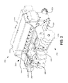
- FIG. 7 is a side view of a seeder with the disc blade assembly and showing the various mechanisms used to control seeding from the different seed boxes, in accordance with various embodiments.
- FIG. 8 is a picture of the different seed distribution options that may distribute seeds at different depths, in accordance with various embodiments.
- phrases “A and/or B” and “A or B” mean (A), (B), or (A and B).
- phrase “A, B, and/or C” means (A), (B), (C), (A and B), (A and C), (B and C), or (A, B and C).
- Existing seeders have a variety of drawbacks.
- some seeders may be configured with a roller on a front portion of the seeder.
- the roller may be useful for tearing up large portions of turf as it travels behind a tractor.
- it may be more desirable to till the turf and create specific furrows.
- a disc blade may be preferable to the roller, and so a different seeder may be required for that application.
- a calibration tray may be provided in the seeder, but the tray is not removable. Additionally, the tray may have a width close to the width of the seeder, so a substantial amount of seed may be required, and possibly wasted, to calibrate the seeder.
- different types of seed may be kept in different seed boxes. However, in some applications it may be desirable to plant the different types of seed at different depths. In other applications it may be desirable to plant the different types of seed at the same depth.
- a seeder which may interchangeably use a roller assembly or a disc blade assembly. Therefore, the operator may have the option of using either rollers or disc blades depending on the application for which the seeder is being configured.
- embodiments of the present disclosure may include a removable calibration tray, thereby simplifying calibration of the seeder.
- the calibration tray may have a width less than the width of the seeder such that less seed may be necessary to accurately calibrate a seed box of the seeder.
- embodiments of the present disclosure may include the option to distribute two different types of seed from two different seed boxes for planting at either the same or different depths.
- embodiments of the present disclosure may be operable as a turf reconditioning tool, a primary seeder, and/or a food plot and conservation seeder. Additionally, embodiments of the present disclosure may be customizable for different types of turf such that a healthy root system may be developed for the seeds distributed by the seeder. Although embodiments coupled with a roller assembly or disc blade assembly are described herein, in other embodiments the seeder may be configured to couple with an assembly using a different type of tillage or turf conditioning tool.
- FIG. 1 depicts an example of a seeder 100 with a roller assembly 104 on a front portion of the seeder 100 .
- the seeder 100 may include one or more of a native seed box 108 , a primary seed box 112 , and/or a legume seed box 116 .
- the seeder 100 may be configured to attach to a tractor or some other powered vehicle, for example using latches 128 , and be pulled behind the tractor or vehicle.
- the seeder 100 may have a width between approximately 60′′ and 100′′, with a working width between approximately 45′′ and 85′′. However, in other embodiments the seeder 100 may be wider or narrower.
- the native seed box 108 may have a capacity between approximately 5 and 10 bushels (bu), though in other embodiments the native seed box 108 may have larger or smaller capacities.
- the native seed box 108 may be configured to hold and distribute long-stem prairie seed such as big blue stem, brome, indian, little blue stem, side oats grama, and/or brassica grasses.
- the primary seed box 112 may be configured to plant large seeds such as soybeans, grass seeds, or small legume seeds. Specifically, the primary seed box 112 may have a capacity between approximately 4 and 8 bu, though in other embodiments the primary seed box 112 may have larger or smaller capacities.
- the primary seed box 112 may be configured to hold and distribute seed such as annual rye grass, barley, Kentucky blue grass blends, fescue, oats, orchard grass, perennial rye grass, snow peas, sorghum, soybeans, sunflower, sudan, and/or wheat.
- the legume seed box 116 may have a capacity between approximately 1 and 2 bu, though in other embodiments the legume seed box 116 may have larger or smaller capacities.
- the legume seed box 116 may be configured to hold and distribute alfalfa, bahai, bermuda, birdsfoot tree foil, brassica, buckwheat, carpet grass, centipede, chicory, clover, fescue, forbs, Kentucky blue grass, radish, rape, sudan, switch grass, timothy, and/or turnip.
- the seeder 100 may only have one, two, or all three of the native, primary, and legume seed boxes 108 , 112 , and 116 .
- Other embodiments may have additional seed boxes configured to hold additional kinds of seed, or duplicate boxes configured in the same or similar manner to boxes 108 , 112 , and/or 116 .
- the seeder 100 may further include a cultipacker 124 attached to a rear portion of the seeder 100 .
- the cultipacker 124 may be configured to firm the seed bed by having a weight sufficient to press down on the seedbed.
- the cultipacker 124 may be desirable for use with relatively small seeds such as those that may be distributed by the primary seed box 112 or the legume seed box 116 .
- the seeder 100 may further include a rear roller 120 that may be configured to firm and press soil kicked up by a front tillage tool of the seeder 100 such as the roller assembly 104 or the disc blade assembly described below with respect to FIG. 2 .
- firming the soil with the rear roller 120 may help to create a uniform seedbed with the loose soil necessary for ensuring proper seed germination.
- the motion of the rear roller 120 may provide the energy used to distribute seed from one or more of the native, primary, and/or legume seed boxes 108 , 112 , and 116 .
- the roller assembly 104 may be coupled with one or more toolbars of the seeder 100 , as shown in greater detail below in FIG. 5 -A.
- the roller assembly 104 may include two rollers 132 .
- the roller assembly 104 may include a greater or lesser number of rollers 132 .
- the rollers 132 and 120 may have a diameter of approximately 8′′, though greater or lesser roller diameters may be used in other embodiments.
- the rollers 132 and 120 may have spike roller pins 136 protruding from the rollers 132 and 120 .
- the spike roller pins 136 may measure approximately 1 ⁇ 2′′ ⁇ 13 ⁇ 4′′, though in other embodiments the spike roller pins 136 may have other measurements.
- the rollers 132 and 120 may have between approximately 256 and 448 spike roller pins 136 , though in other embodiments one or both of the rollers 132 and 120 may have more or less spike roller pins 136 . In some embodiments rollers 132 may have the same number of spike roller pins as roller 120 , and in other embodiments rollers 132 and 120 may have different numbers of spike roller pins. In some embodiments, each of the front rollers 132 may have the same number of spike roller pins 136 as one another, or a different number of spike roller pins 136 .
- the roller assembly 104 may further include an adjustment mechanism 140 configured to adjust the angle of the rollers 132 as described in further detail below with respect to FIGS. 5 -A and 5 -B.
- the adjustment mechanism 140 may include an adjustment lever 144 to enable an operator of the seeder 100 to adjust the roller assembly 104 .
- the adjustment mechanism 140 may further include one or more mast plates 148 configured to overlay the adjustment mechanism 140 and connect the seeder 100 to a tractor (not shown).
- FIG. 2 depicts an alternative embodiment of a seeder 200 .
- the native seed box is missing at 205 , and instead a plurality of seed cups of the primary box are illustrated at 205 .
- the seed box may have between 7 and 12 seed cups that span the width of the seeder 200 .
- the roller assembly 104 described above in FIG. 1 is replaced by a disc blade assembly 210 .
- the disc blade assembly 210 is configured with a gang of disc blades 215 .
- each disc blade in the gang of disc blades 215 may be a notched disc blade approximately 18′′ in diameter, though in other embodiments the disc blades may be smaller or larger.
- the disc blades in the gang of disc blades 215 may be approximately 7-8′′ from one another, though in other embodiments the disc blades may be closer together or further apart.
- the seeder 200 has elements similar to those of the seeder 100 shown in FIG. 1 , for example rear roller 220 , latches 228 , adjustment mechanism 240 , adjustment lever 244 , mast plates 248 , cultipacker 224 , primary seed box 212 , and legume seed box 216 .
- the roller assembly 104 and the disc blade assembly 210 may be removable such that an operator of the seeder 100 or 200 has the capability to, for example, exchange the roller assembly 104 with the disc blade assembly 210 , or vice versa, dependent upon the application that the seeder 100 or 200 will be used for.
- the same seeder may be used for a tilling application when coupled with the disc blade assembly 210 , as well as turf conditioning when coupled with the roller assembly 104 .
- FIG. 3 is a side view of a seeder 300 with a roller assembly 304 .
- seeder 300 may include two rollers 332 with spike roller pins 336 in the roller assembly 304 , as well as a rear roller 320 and a cultipacker 324 .
- the seeder 300 may further include native, primary, and legume seed boxes 308 , 312 , and 316 .
- seeder 300 may not include the cultipacker 324 .
- the seeder 300 may only include 1, 2, or all 3 of the native, primary, and legume seed boxes 308 , 312 , and 316 .
- the seeder 300 may further include a removable calibration tray which may be used to calibrate the output of the primary seed box 312 or the legume seed box 316 of the seeder 300 .
- the calibration tray may be stored at the storage position 352 .
- the calibration tray may be removed from the seeder 300 and installed at the legume and primary collection slot 356 .
- a known amount of seed for example one or two pounds of seed, may be put in the desired seed box, e.g. the primary seed box 312 or the legume seed box 316 , and the seed box may be set to a known setting.
- the seed box may have a number of seed cups, and the seed cups may be set at the halfway position.
- the seed may be placed directly in the seed cups.
- the calibration tray may not extend all the way across the width of the seeder 300 , but instead may have a width less than that of the seeder. Therefore, if the calibration tray is inserted into the right side of the seeder 300 , the seed may be placed directly into the right-most seed cups of the seeder 300 .
- the calibration tray may only be approximately as wide as two seed cups of the seeder 300 .
- the seeder 300 may have between 7 and 12 seed cups. Therefore, the calibration tray may have a width that is between approximately 15% and 30% of the width of the seeder 300 .
- the calibration tray may have a width between approximately 10′′ and 30′′. In some embodiments, the calibration tray may be wider or narrower, for example having a width that is equivalent to between one and four seed cups. A calibration tray with a width less than that of the seeder 300 may reduce the amount of seed necessary to successfully perform the calibration procedure.
- a seed box shaft of the seed box may be rotated.
- the seeder 300 may include a calibration crank handle used to rotate the seed box shaft, while in other embodiments the seed box shaft may be rotated using a socket wrench or some other way of turning the seed box shaft.
- the legume seed box 316 is being calibrated
- the legume seed box shaft 360 may be rotated.
- the primary seed box 312 is being calibrated
- the primary seed box shaft 364 may be rotated. Rotation of the seed box shaft may cycle seed through the seed box, and deposit the seed on the calibration tray in the legume and primary collection slot 356 .
- the amount of the seed on the calibration tray may then be used to determine the rate at which seed is being deposited by the seeder 300 , and the operator may use that information to determine whether to adjust the flow rate of the seed box.
- the gearing of the seed box shafts 360 or 364 may be known, and so it may be easy to determine how many rotations of the seed box shafts 360 or 364 are necessary to simulate travel of the seeder 300 over a given area. That information may then be extrapolated from the small simulated area to a larger area.
- the primary or legume seed boxes 312 or 316 may have levers, knobs, dials, or some other method of adjusting the output flow rate of the seed box. If the amount of seed being output is determined by the calibration procedure to be too great, then the amount of output seed may be reduced. By contrast, if the amount of seed being output is determined by the calibration procedure to be too little, then the amount of output seed may be increased.
- the native seed box 308 may be likewise calibrated, for example by installing the calibration tray at the native collection slot 368 . Additionally, in some embodiments the calibration procedure may be performed by using a tractor to move the seeder 300 over a known distance instead of manually rotating the seed box shafts 360 or 364 .
- FIG. 4 depicts a side view of a seeder 400 coupled with the disc blade assembly 410 and a gang of disc blades 415 .
- the seeder 400 may further include elements of seeders 100 , 200 , or 300 , including for example the native, primary and legume seed boxes 408 , 412 , and 416 , a rear roller 420 , a cultipacker 424 , legume and primary seed box shafts 460 and 464 , a native collection slot 468 , a calibration tray storage position 452 , and a legume and primary collection slot 456 .
- FIGS. 5 -A and 5 -B depict top-down views of a seeder 500 .
- the mast plate and native seed box of the seeder 500 are not displayed in FIGS. 5 -A and 5 -B.
- the top down view more directly illustrates how rollers 532 are connected to the frame of the seeder.
- the rollers 532 may be respectively mounted to bars such as a right bar 572 a and a left bar 572 b .
- the bars may be a three inch by three inch metal bar or a three inch square tubing, though in other embodiments the bars may be different widths or of different shapes.
- the bars may be rectangular, circular, or some other shape, and may be either solid, hollow, or semi-hollow.
- the right bar 572 a and the left bar 572 b may be offset from each other such that the left bar 572 b is closer to the front of the seeder 500 than the right bar 572 a .
- This configuration may be useful when rollers 532 are sized and configured to at least partially overlap.
- the right bar 572 a may be in front of the left bar 572 b , and in other embodiments the right and left bars 572 a and 572 b may be lined up with one another in the front-to-back direction.
- the right and left bars 572 a and 572 b may be coupled with the frame of the seeder 500 at frame connection points 576 a and 576 b , respectively.
- the frame connection points 576 a and 576 b may be loose, hinged, or otherwise moveable such that the right and left bars 572 a and 572 b may be angled, as described in greater detail below.
- the seeder 500 may further include an adjustment mechanism 540 including a stationary tray 580 with a number of different positions.
- the adjustment mechanism 540 may further include a studded roller slide 584 .
- the stationary tray 580 may remain static with respect to the frame of the seeder 500 , while the studded roller slide 584 may move with respect to the stationary tray 580 and the frame of the seeder 500 .
- the studded roller slide 584 may be latched to a position of the stationary tray 580 , for example using a pin, a latch, or some other fastener 588 .
- the studded roller slide 584 may be attached to the right and left bars 572 a and 572 b at right and left connection points 592 a and 592 b.
- the adjustment mechanism 540 may be used to adjust the angle ⁇ of the rollers 532 with respect to the seeder 500 , as shown in FIG. 5 -B.
- the fastener 588 may be removed, and the studded roller slide 584 may be moved forward with respect to the seeder 500 and the stationary tray 580 .
- the studded roller slide 584 may be moved using an adjustment lever such as adjustment lever 144 shown above (not shown here for ease of illustration).
- the adjustment lever may be coupled with the studded roller slide 584 and configured to be used by the operator to move the studded roller slide 584 with respect to the stationary tray 580 .
- the studded roller slide 584 may be coupled with the stationary tray 580 using the fastening 588 .
- the studded roller slide 584 may be coupled with the stationary tray 580 at eight distinct positions, and angle ⁇ may range from 0° to 30°.
- angle ⁇ may range from 0° to 30°.
- a seeder 500 with a lower width may be configured to have a greater maximum angle ⁇ .
- the seeder 500 may have a different range of angles ⁇ , including a negative angle ⁇ .
- the studded roller slide 584 may have a greater or lesser number of positions with respect to the stationary tray 580 .
- the spike roller pins may penetrate soil in a straight pushing action, thereby creating holes for seeds to be deposited into, and aerating the turf, but otherwise causing relatively little disturbance to the turf.
- the spike roller pins may cause a more aggressive tearing action to the turf, thereby disturbing the turf more.
- a greater angle ⁇ will cause more disturbance to the turf, and so a maximum angle ⁇ may be desirable for severe turf conditions.
- FIGS. 6 -A and 6 -B show a top-down view of a seeder 600 .
- seeder 600 utilizes the disc blade assembly with the gang of disc blades 615 , as discussed above with respect to FIG. 2 and elsewhere.
- the gang of disc blades 615 is coupled with a right bar 672 a and a left bar 672 b .
- the right bar and left bar 672 a and 672 b are moveably coupled with the frame of the seeder 600 at frame connection points 676 a and 676 b , which may be hinged or otherwise moveably coupled with to the frame of the seeder 600 .
- the right and left bars 672 a and 672 b are coupled at connection points 682 a and 682 b with a moveable connector 696 , which in turn is coupled with the stationary tray 680 .
- the right and left bars 672 a and 672 b are relatively even with one another with respect to the front of the seeder 600 , as shown in FIG. 6 -A.
- the right and left bars 672 a and 672 b may be offset with respect to one another.
- the moveable connector 696 may be moved with respect to the stationary tray 680 using an adjustment lever such as adjustment lever 144 shown above (not shown here for ease of illustration), which may result in the gang of disc blades 615 rotating by angle ⁇ , for example as shown in FIG. 6 -B.
- This rotation may occur because the connection points 682 a and 682 b may move toward the rear of the seeder 600 if the moveable connector 696 is moved toward the rear of the seeder, while the frame connection points 676 a and 676 b remain stationary.
- the angle ⁇ may be between 0° and 25°, though in other embodiments the angle ⁇ may be greater or lesser, for example being a negative angle.
- the moveable connector 696 may have four distinct positions with respect to the stationary tray 680 , while in other embodiments may have more or less positions.
- the seeder 600 using the gang of disc blades 615 may be used to prepare a seedbed without the need for a separate disc blade or tillage tool used ahead of time.
- the seeder 600 may create a relatively small amount of soil disturbance.
- the gang of disc blades 615 are angled, for example as shown in FIG. 6 -B, then the disc blades may create a very large amount of soil disturbance.
- the seeder 500 may use the moveable connector 696 , for example if the right and left bars 572 a and 572 b are relatively even with one another with respect to the front of the seeder 500 .
- the seeder 600 may use the studded roller slide 584 of seeder 500 , for example if the right and left bars 672 a and 672 b are offset with respect to one another.
- FIG. 7 depicts an example of a seeder 700 showing one possible configuration for the various disconnects that can be used to power one or more of the native seed box 708 , the primary seed box 712 , and/or the legume seed box 716 .
- seeder 700 includes a disc blade assembly 710 comprising a gang of disc blades 715 .
- the disconnect system may be similarly used in a seeder containing a roller assembly, such as roller assembly 104 discussed above.
- seeder 700 may contain all or some of the elements discussed above in FIGS. 1-6 .
- the seeder 700 may be powered by the rotation of the roller 720 as the seeder 700 is pulled behind a tractor or some other vehicle.
- the seeder 700 may further include a main disconnect 725 .
- the main disconnect 725 may include an axle and a gear such that when the axle rotates, the gear does not rotate if the main disconnect 725 is inoperative.
- the axle of the main disconnect 725 may be the axle of the roller 720 .
- the main disconnect 725 may be made operative by coupling the axle of the roller 720 with the gear of the main disconnect 725 . This coupling may occur through insertion of a fastener.
- the fastener may be a cotter pin, a klik pin, a ball-detent pin, a safety pin, or some other type of pin or fastener.
- the rotation of the main disconnect 725 may be tied to the roller 720 such that the gear of the main disconnect 725 rotates when the roller 720 rotates.
- the “gear” described above with respect to the main disconnect 725 may be a sprocket used to drive a chain and/or a gear used to drive another gear. Throughout the rest of this disclosure, the term “gear” will be used with respect to disconnects, but it may be understood that the term may encompass one or both of a sprocket and/or gear.
- gears 735 may include a plurality of different gears, for example a 15/30 or a 15/40 gear such that the gears 735 may be used to translate the speed of the main chain 730 into a different speed for a different chain, for example primary chain 750 .
- the seeder 700 may have a different size of gears.
- the gears 735 may in turn be coupled with the primary disconnect 745 via a primary chain 750 .
- the primary disconnect 745 may contain a gear and an axle.
- the primary chain 750 may cause the gear of the primary disconnect 745 to rotate. If the primary disconnect 745 is operative, that is the axle of the primary disconnect 745 is coupled to the gear of the primary disconnect 745 through a fastener such as the fastener described above, then the rotation of the primary disconnect 745 may power the primary seed box 712 and cause the primary seed box 712 to disperse seed.
- the primary disconnect 745 also be coupled with the native seed box disconnect 755 by a second primary chain 765 .
- the native seed box disconnect 755 may be configured to cause the native seed box 708 to disperse seed when the native seed box disconnect 755 is operative. That is, the native seed box disconnect 755 may rotate based upon rotation of the second primary chain 765 as described above with respect to the main disconnect 725 and the primary disconnect 745 .
- the native seed box disconnect 755 may be coupled with the native seed box 708 using a native chain 770 as shown in FIG. 7 .
- the primary disconnect 745 may be coupled with a legume box disconnect 775 using a legume chain 785 .
- the legume box disconnect 775 When the legume box disconnect 775 is operative, then it may cause the legume box 716 to disperse seed when the legume chain 785 rotates.
- disconnects such as the primary disconnect 745 may include a plurality of gears, and in some embodiments the gears may be coupled with one another. Therefore, when the gear of the primary disconnect 745 rotates, even if the primary disconnect 745 is inoperative, then a chain coupled with the primary disconnect 745 such as the legume chain 785 may still move. Therefore, the seeder 700 shown in FIG. 7 may be configured by an operator to use one or both of the legume seed box 716 or the native seed box 708 without use of the primary seed box 712 .
- the disconnect system of seeder 700 is merely one example, and different configurations and connections using a greater or lesser number of chains and/or disconnects may be used in other embodiments.
- the main disconnect 725 is inoperative, then the main chain 730 may not rotate when the roller 720 rotates, and therefore none of the other disconnects 745 , 755 , or 775 may rotate.
- FIG. 8 shows a configuration wherein seed can be placed into a front tray 890 and a rear tray 895 using the depicted tubes.
- the front tray 890 may be configured to disperse the seed in front of a rear roller, for example rear roller 120 shown in FIG. 1 .
- the rear tray 895 may be configured to disperse the seed behind the rear roller and in front of the cultipacker, for example cultipacker 124 shown in FIG. 1 .
- the rear roller may press the seed farther into the earth if the seed is deposited from the front tray 890 , while the cultipacker may allow the seed to remain at a relatively shallow depth, therefore seed from the front tray 890 may be planted by the seeder at a deeper depth than seed from the rear tray 895 .
- the tubes may be used to deposit seed from the same source to the front and rear trays 890 and 895 .
- the tubes may be adjusted by an operator to deposit seed only into one of the front or rear trays 890 and 895 .
- the seed may come from the same source, for example the legume seed box only, while in other embodiments the seed may come from different sources, for example the primary seed box and/or the legume seed box.
- the cultipacker may be missing from the seeder, and the seed from the rear tray 895 may stay at the level of the turf without being pressed into the turf.
- a seeder may include a frame including a front end and a rear end, the front end of the frame configured to be coupled with a vehicle; a rear roller coupled with the frame; and a seed box coupled with the frame and configured to disperse seed, wherein the frame is configured to removably couple with an attachment including a roller assembly or a disc blade assembly.
- the seeder may further include an adjustment module configured to couple with the attachment.
- the adjustment module may be configured to angle a roller of the roller assembly or a disc blade of the disc blade assembly.
- a seeder may include a frame coupled with a first seed box configured to distribute a first kind of seed and a second seed box configured to distribute a second kind of seed; a rear roller coupled with the frame; a front tray configured to receive the first kind of seed from the first seed box and the second kind of seed from the second seed box and further configured to disperse the first and second kinds of seed at a position in front of the rear roller.
- the seeder may further include a rear tray configured to receive the first kind of seed from the first seed box and the second kind of seed from the second seed box and further configured to disperse the first and second kinds of seed at a position behind the rear roller.
- the front tray may be configured to receive the first kind of seed from the first seed box concurrently with the rear tray being configured to receive the second kind of seed from the second seed box.
- the seeder may be configured to plant the first kind of seed at a first depth and configured to plant the second kind of seed at a second depth, wherein the first and second depths are different.
- a seeder may include a frame coupled with a seed box, the seed box configured to disperse seed through an outlet of the frame; and a calibration tray configured to removably couple with the outlet to receive seed from the seed box, wherein the calibration tray has a width less than a width of the frame.
- the width of the calibration tray may be less than 50% of the width of the frame.
- the seed box may include a plurality of seed cups, and the width of the calibration tray may be less than or equal to a width of four seed cups.
Abstract
Description
Claims (12)
Priority Applications (1)
| Application Number | Priority Date | Filing Date | Title |
|---|---|---|---|
| US14/748,072 US9456544B2 (en) | 2013-03-15 | 2015-06-23 | Precision super seeder |
Applications Claiming Priority (2)
| Application Number | Priority Date | Filing Date | Title |
|---|---|---|---|
| US13/838,004 US9439343B2 (en) | 2013-03-15 | 2013-03-15 | Precision super seeder |
| US14/748,072 US9456544B2 (en) | 2013-03-15 | 2015-06-23 | Precision super seeder |
Related Parent Applications (1)
| Application Number | Title | Priority Date | Filing Date |
|---|---|---|---|
| US13/838,004 Division US9439343B2 (en) | 2013-03-15 | 2013-03-15 | Precision super seeder |
Publications (2)
| Publication Number | Publication Date |
|---|---|
| US20150289440A1 US20150289440A1 (en) | 2015-10-15 |
| US9456544B2 true US9456544B2 (en) | 2016-10-04 |
Family
ID=51521584
Family Applications (3)
| Application Number | Title | Priority Date | Filing Date |
|---|---|---|---|
| US13/838,004 Active 2033-08-14 US9439343B2 (en) | 2013-03-15 | 2013-03-15 | Precision super seeder |
| US14/748,072 Active US9456544B2 (en) | 2013-03-15 | 2015-06-23 | Precision super seeder |
| US14/748,064 Active US9456543B2 (en) | 2013-03-15 | 2015-06-23 | Precision super seeder |
Family Applications Before (1)
| Application Number | Title | Priority Date | Filing Date |
|---|---|---|---|
| US13/838,004 Active 2033-08-14 US9439343B2 (en) | 2013-03-15 | 2013-03-15 | Precision super seeder |
Family Applications After (1)
| Application Number | Title | Priority Date | Filing Date |
|---|---|---|---|
| US14/748,064 Active US9456543B2 (en) | 2013-03-15 | 2015-06-23 | Precision super seeder |
Country Status (2)
| Country | Link |
|---|---|
| US (3) | US9439343B2 (en) |
| CA (1) | CA2831244C (en) |
Cited By (2)
| Publication number | Priority date | Publication date | Assignee | Title |
|---|---|---|---|---|
| CN109297852A (en) * | 2018-11-14 | 2019-02-01 | 彭佃亮 | A kind of use for laboratory wheat seed mass of 1000 kernel instrument |
| US11576293B2 (en) | 2020-07-06 | 2023-02-14 | Blake Paul Patton | Agricultural planter depth calibration block |
Families Citing this family (16)
| Publication number | Priority date | Publication date | Assignee | Title |
|---|---|---|---|---|
| CN105325100A (en) * | 2015-11-04 | 2016-02-17 | 董保安 | Soybean-corn alternate sowing machine |
| CN107018723A (en) * | 2016-01-29 | 2017-08-08 | 广西高农机械有限公司 | A kind of accurate seeder |
| CN107018724A (en) * | 2016-01-29 | 2017-08-08 | 广西高农机械有限公司 | A kind of multi-functional accurate seeder |
| CN105830596A (en) * | 2016-05-19 | 2016-08-10 | 武汉黄鹤拖拉机制造有限公司 | Pneumatic precision seeder |
| DE102016012254A1 (en) * | 2016-10-14 | 2018-04-19 | Rauch Landmaschinenfabrik Gmbh | Pneumatic distributor and method for controlling or regulating the metering devices by means of calibration tests |
| CN107873191A (en) * | 2017-12-08 | 2018-04-06 | 铜陵汇宇实业有限公司 | A kind of novel pneumatic seeder |
| CN108575217B (en) * | 2018-03-30 | 2020-12-18 | 华中农业大学 | Electrically-driven centrifugal seed metering device capable of independently starting and stopping each row as required |
| CN108633401A (en) * | 2018-05-11 | 2018-10-12 | 桐城市天地泰农业科技有限公司 | Spherical particle seed seeding apparatus |
| CN108738539B (en) * | 2018-06-17 | 2020-03-17 | 蒙城县育田机械有限公司 | Fertilizing and seeding machine capable of adjusting seeding rate |
| CN108811622B (en) * | 2018-06-28 | 2021-10-29 | 许立胜 | Grass seed particle spraying machine for agricultural pasture |
| CN110089238A (en) * | 2019-05-10 | 2019-08-06 | 南县伟业机械制造有限公司 | A kind of implanted device |
| CN110301269B (en) * | 2019-08-05 | 2021-03-30 | 山东青岛烟草有限公司 | Multifunctional tobacco sowing system |
| US11770989B1 (en) | 2020-08-25 | 2023-10-03 | Abi Attachments Inc. | Tow-behind roller tool apparatuses, systems and methods |
| CN112970385A (en) * | 2021-02-08 | 2021-06-18 | 胡伟 | Seeder for farming |
| CN114616958B (en) * | 2022-02-28 | 2023-09-01 | 江汉大学 | Transplanting vehicle and automatic transplanting method thereof |
| CN114531984B (en) * | 2022-03-18 | 2024-04-05 | 华中农业大学 | Rotary tillage ridging web rotary-cut type rape micro-ridge precise combined direct seeding machine |
Citations (7)
| Publication number | Priority date | Publication date | Assignee | Title |
|---|---|---|---|---|
| US2221769A (en) | 1937-04-17 | 1940-11-19 | Int Harvester Co | Tractor attachment |
| US2811089A (en) | 1955-03-25 | 1957-10-29 | James B Blackstone | Steering means for row crop cultivators and the like |
| US3153456A (en) | 1963-03-06 | 1964-10-20 | Billy M Noble | Plant bed shaper |
| JPH06276813A (en) * | 1993-03-26 | 1994-10-04 | Matsuyama Plow Mfg Co Ltd | Sowing device |
| US20040079264A1 (en) * | 2002-10-29 | 2004-04-29 | Mayerle Dean J. | Dual capability nurse distribution system |
| US20050235890A1 (en) * | 2004-04-26 | 2005-10-27 | Mariman Nathan A | Agricultural machine with variable pressure product distribution system |
| US20060260523A1 (en) * | 2003-03-29 | 2006-11-23 | Claydon Jeffrey T | Seed drill |
Family Cites Families (4)
| Publication number | Priority date | Publication date | Assignee | Title |
|---|---|---|---|---|
| US2532726A (en) | 1946-10-16 | 1950-12-05 | Louis J Lajoie | Bird feeder |
| US2865326A (en) | 1957-08-15 | 1958-12-23 | Jr Henry Edward Lowe | Bird feeders |
| US3425602A (en) | 1967-02-21 | 1969-02-04 | Julius C Tucci | One-piece seed dispensing carton |
| US5205239A (en) | 1992-05-08 | 1993-04-27 | Walter Stolwein | Bird feeding device with squirrel guard |
-
2013
- 2013-03-15 US US13/838,004 patent/US9439343B2/en active Active
- 2013-10-24 CA CA2831244A patent/CA2831244C/en active Active
-
2015
- 2015-06-23 US US14/748,072 patent/US9456544B2/en active Active
- 2015-06-23 US US14/748,064 patent/US9456543B2/en active Active
Patent Citations (7)
| Publication number | Priority date | Publication date | Assignee | Title |
|---|---|---|---|---|
| US2221769A (en) | 1937-04-17 | 1940-11-19 | Int Harvester Co | Tractor attachment |
| US2811089A (en) | 1955-03-25 | 1957-10-29 | James B Blackstone | Steering means for row crop cultivators and the like |
| US3153456A (en) | 1963-03-06 | 1964-10-20 | Billy M Noble | Plant bed shaper |
| JPH06276813A (en) * | 1993-03-26 | 1994-10-04 | Matsuyama Plow Mfg Co Ltd | Sowing device |
| US20040079264A1 (en) * | 2002-10-29 | 2004-04-29 | Mayerle Dean J. | Dual capability nurse distribution system |
| US20060260523A1 (en) * | 2003-03-29 | 2006-11-23 | Claydon Jeffrey T | Seed drill |
| US20050235890A1 (en) * | 2004-04-26 | 2005-10-27 | Mariman Nathan A | Agricultural machine with variable pressure product distribution system |
Cited By (3)
| Publication number | Priority date | Publication date | Assignee | Title |
|---|---|---|---|---|
| CN109297852A (en) * | 2018-11-14 | 2019-02-01 | 彭佃亮 | A kind of use for laboratory wheat seed mass of 1000 kernel instrument |
| CN109297852B (en) * | 2018-11-14 | 2021-09-14 | 潍坊科技学院 | Wheat seed thousand grain weight instrument for laboratory |
| US11576293B2 (en) | 2020-07-06 | 2023-02-14 | Blake Paul Patton | Agricultural planter depth calibration block |
Also Published As
| Publication number | Publication date |
|---|---|
| US20150289440A1 (en) | 2015-10-15 |
| US20150289439A1 (en) | 2015-10-15 |
| CA2831244A1 (en) | 2014-09-15 |
| US9456543B2 (en) | 2016-10-04 |
| US9439343B2 (en) | 2016-09-13 |
| CA2831244C (en) | 2017-12-12 |
| US20140261119A1 (en) | 2014-09-18 |
Similar Documents
| Publication | Publication Date | Title |
|---|---|---|
| US9456544B2 (en) | Precision super seeder | |
| US11284552B2 (en) | Row unit for selectively dispensing a plurality of agricultural products and associated agricultural implements | |
| US4241674A (en) | Sub-soil planter | |
| Kamgar et al. | Design, development and field assessment of a controlled seed metering unit to be used in grain drills for direct seeding of wheat | |
| CN201091095Y (en) | No-tillage fertilizing and sowing machine for grain | |
| Sharaby et al. | A comparative analysis of precision seed planters | |
| Haque et al. | An innovative versatile multi-crop planter for crop establishment using two-wheel tractors | |
| CN103098592A (en) | Large-ridge double-row buckwheat sowing machine | |
| CN112292973A (en) | Seeding machine | |
| Singh et al. | Development and performance evaluation of manual/bullock operated multicrop planter for hilly region | |
| Koronka | Machinery development for direct drilling | |
| CN110192450B (en) | Seeding unit for a combined agricultural machine | |
| CN210352111U (en) | Seeding machine | |
| Verma et al. | Development and evaluation of cultivator cum seed drill | |
| CN206620425U (en) | no-tillage machine | |
| CN106211873A (en) | A kind of an animal-drawn seed plough lower limb is dredged stifled device and dredges the width seeder of stifled device equipped with this | |
| Hossen et al. | Improvement of the seed metering device of power tiller operated zero till drill | |
| CN212413794U (en) | Agricultural multifunctional seeder | |
| CN201057702Y (en) | Seed tray of corn seeder | |
| CN212876583U (en) | Quick planting device of crop seed | |
| CN220173771U (en) | Quantitative sowing mechanism of sowing machine | |
| Osadare et al. | Performance Evaluation of A Pulse Planter Developed for Conservation Agriculture | |
| CN106576516A (en) | Small precise corn interplanting dibbler | |
| CN205611217U (en) | Centrifugal no -tillage seeder | |
| Yusuf et al. | DESIGN, FABRICATION AND PERFORMANCE EVALUATION OF A MOTORIZED 2–ROW SOYBEAN PLANTER FOR SMALL SCALE FARMERS IN KATSINA STATE |
Legal Events
| Date | Code | Title | Description |
|---|---|---|---|
| AS | Assignment |
Owner name: BLOUNT, INC., OREGON Free format text: ASSIGNMENT OF ASSIGNORS INTEREST;ASSIGNORS:WEHLER, TODD M.;SARVER, CORY E.;REEL/FRAME:036583/0930 Effective date: 20130319 |
|
| AS | Assignment |
Owner name: BARCLAYS BANK PLC, AS COLLATERAL AGENT, NEW YORK Free format text: SECURITY INTEREST;ASSIGNOR:WOODS EQUIPMENT COMPANY;REEL/FRAME:038267/0017 Effective date: 20160412 |
|
| STCF | Information on status: patent grant |
Free format text: PATENTED CASE |
|
| FEPP | Fee payment procedure |
Free format text: PAYOR NUMBER ASSIGNED (ORIGINAL EVENT CODE: ASPN); ENTITY STATUS OF PATENT OWNER: LARGE ENTITY |
|
| MAFP | Maintenance fee payment |
Free format text: PAYMENT OF MAINTENANCE FEE, 4TH YEAR, LARGE ENTITY (ORIGINAL EVENT CODE: M1551); ENTITY STATUS OF PATENT OWNER: LARGE ENTITY Year of fee payment: 4 |
|
| AS | Assignment |
Owner name: OREGON TOOL, INC., OREGON Free format text: CHANGE OF NAME;ASSIGNOR:BLOUNT, INC.;REEL/FRAME:055304/0480 Effective date: 20210128 |
|
| AS | Assignment |
Owner name: BANK OF AMERICA, N.A., AS COLLATERAL AGENT, NORTH CAROLINA Free format text: SECURITY AGREEMENT (TERM LOAN);ASSIGNORS:OREGON TOOL, INC.;SPEECO, INCORPORATED;WOODS EQUIPMENT COMPANY;REEL/FRAME:057827/0381 Effective date: 20211015 Owner name: WOODS EQUIPMENT COMPANY, OREGON Free format text: RELEASE OF SECURITY INTEREST IN PATENTS RECORDED AT R/F 038267/0017;ASSIGNOR:BARCLAYS BANK PLC, AS COLLATERAL AGENT;REEL/FRAME:057827/0260 Effective date: 20211015 |
|
| AS | Assignment |
Owner name: BANK OF AMERICA, N.A., AS COLLATERAL AGENT, NORTH CAROLINA Free format text: SECURITY AGREEMENT (ABL);ASSIGNORS:OREGON TOOL, INC.;SPEECO, INCORPORATED;WOODS EQUIPMENT COMPANY;REEL/FRAME:057859/0549 Effective date: 20211015 |
|
| MAFP | Maintenance fee payment |
Free format text: PAYMENT OF MAINTENANCE FEE, 8TH YEAR, LARGE ENTITY (ORIGINAL EVENT CODE: M1552); ENTITY STATUS OF PATENT OWNER: LARGE ENTITY Year of fee payment: 8 |