US9451610B2 - Wireless terminal and base station - Google Patents
Wireless terminal and base station Download PDFInfo
- Publication number
- US9451610B2 US9451610B2 US14/177,831 US201414177831A US9451610B2 US 9451610 B2 US9451610 B2 US 9451610B2 US 201414177831 A US201414177831 A US 201414177831A US 9451610 B2 US9451610 B2 US 9451610B2
- Authority
- US
- United States
- Prior art keywords
- sps
- pdcch
- base station
- services
- wireless terminal
- Prior art date
- Legal status (The legal status is an assumption and is not a legal conclusion. Google has not performed a legal analysis and makes no representation as to the accuracy of the status listed.)
- Active, expires
Links
- 238000004891 communication Methods 0.000 claims abstract description 317
- 230000004913 activation Effects 0.000 claims abstract description 118
- 230000000737 periodic effect Effects 0.000 claims abstract description 25
- 238000000034 method Methods 0.000 claims description 49
- 230000008569 process Effects 0.000 claims description 39
- 125000004122 cyclic group Chemical group 0.000 claims description 9
- 101000587820 Homo sapiens Selenide, water dikinase 1 Proteins 0.000 description 102
- 101000701815 Homo sapiens Spermidine synthase Proteins 0.000 description 102
- 102100031163 Selenide, water dikinase 1 Human genes 0.000 description 102
- 101000828738 Homo sapiens Selenide, water dikinase 2 Proteins 0.000 description 77
- 102100023522 Selenide, water dikinase 2 Human genes 0.000 description 77
- 230000005540 biological transmission Effects 0.000 description 45
- 101150059145 SPS3 gene Proteins 0.000 description 32
- 230000002776 aggregation Effects 0.000 description 10
- 238000004220 aggregation Methods 0.000 description 10
- 238000010586 diagram Methods 0.000 description 10
- 230000011664 signaling Effects 0.000 description 9
- 101000741965 Homo sapiens Inactive tyrosine-protein kinase PRAG1 Proteins 0.000 description 6
- 102100038659 Inactive tyrosine-protein kinase PRAG1 Human genes 0.000 description 6
- 101100257612 Oryza sativa subsp. japonica SPS3 gene Proteins 0.000 description 4
- 230000006870 function Effects 0.000 description 4
- 238000013468 resource allocation Methods 0.000 description 3
- 101100257625 Oryza sativa subsp. japonica SPS4 gene Proteins 0.000 description 2
- 239000000969 carrier Substances 0.000 description 2
- 238000007726 management method Methods 0.000 description 2
- 238000010295 mobile communication Methods 0.000 description 2
- 230000008520 organization Effects 0.000 description 2
- 230000003068 static effect Effects 0.000 description 2
- 230000004931 aggregating effect Effects 0.000 description 1
- 230000004075 alteration Effects 0.000 description 1
- 230000001413 cellular effect Effects 0.000 description 1
- 230000008859 change Effects 0.000 description 1
- 238000005516 engineering process Methods 0.000 description 1
- 239000004973 liquid crystal related substance Substances 0.000 description 1
- 230000007774 longterm Effects 0.000 description 1
- 230000005236 sound signal Effects 0.000 description 1
- 238000006467 substitution reaction Methods 0.000 description 1
Images


Classifications
-
- H04W72/0433—
-
- H—ELECTRICITY
- H04—ELECTRIC COMMUNICATION TECHNIQUE
- H04W—WIRELESS COMMUNICATION NETWORKS
- H04W72/00—Local resource management
- H04W72/20—Control channels or signalling for resource management
- H04W72/29—Control channels or signalling for resource management between an access point and the access point controlling device
-
- H—ELECTRICITY
- H04—ELECTRIC COMMUNICATION TECHNIQUE
- H04L—TRANSMISSION OF DIGITAL INFORMATION, e.g. TELEGRAPHIC COMMUNICATION
- H04L5/00—Arrangements affording multiple use of the transmission path
-
- H—ELECTRICITY
- H04—ELECTRIC COMMUNICATION TECHNIQUE
- H04L—TRANSMISSION OF DIGITAL INFORMATION, e.g. TELEGRAPHIC COMMUNICATION
- H04L5/00—Arrangements affording multiple use of the transmission path
- H04L5/003—Arrangements for allocating sub-channels of the transmission path
- H04L5/0053—Allocation of signaling, i.e. of overhead other than pilot signals
-
- H—ELECTRICITY
- H04—ELECTRIC COMMUNICATION TECHNIQUE
- H04W—WIRELESS COMMUNICATION NETWORKS
- H04W72/00—Local resource management
- H04W72/12—Wireless traffic scheduling
- H04W72/1263—Mapping of traffic onto schedule, e.g. scheduled allocation or multiplexing of flows
-
- H—ELECTRICITY
- H04—ELECTRIC COMMUNICATION TECHNIQUE
- H04W—WIRELESS COMMUNICATION NETWORKS
- H04W76/00—Connection management
-
- H—ELECTRICITY
- H04—ELECTRIC COMMUNICATION TECHNIQUE
- H04L—TRANSMISSION OF DIGITAL INFORMATION, e.g. TELEGRAPHIC COMMUNICATION
- H04L1/00—Arrangements for detecting or preventing errors in the information received
- H04L1/12—Arrangements for detecting or preventing errors in the information received by using return channel
- H04L1/16—Arrangements for detecting or preventing errors in the information received by using return channel in which the return channel carries supervisory signals, e.g. repetition request signals
- H04L1/18—Automatic repetition systems, e.g. Van Duuren systems
- H04L1/1829—Arrangements specially adapted for the receiver end
- H04L1/1861—Physical mapping arrangements
-
- H—ELECTRICITY
- H04—ELECTRIC COMMUNICATION TECHNIQUE
- H04W—WIRELESS COMMUNICATION NETWORKS
- H04W76/00—Connection management
- H04W76/20—Manipulation of established connections
- H04W76/27—Transitions between radio resource control [RRC] states
Definitions
- the embodiments discussed herein are related to a wireless terminal and a base station for communicating wirelessly.
- LTE Long Term Evolution
- OFDM Orthogonal Frequency Division Multiplexing
- LTE-A LTE-Advanced
- 3GPP 3rd Generation Partnership Project
- LTE-A LTE-Advanced
- the LTE-A targets high peak data rates of 1 Gbps in the downlink and 500 Mbps in the uplink, and various new techniques including wireless access schemes and network architectures have currently been studied.
- a base station informs in advance a wireless terminal of communication periodicity in a radio resource control (RRC) connection on Layer 3 (L3). Then, when actual SPS communication is performed, the base station transmits an activation command to the wireless terminal through the PDCCH.
- RRC radio resource control
- the SPS activation command includes information indicating which radio resources are to be continuously used (see, for example, 3GPP TS 36.321, “Medium Access Control (MAC) protocol specification”, V10.1.0, Release 10, March 2011; and 3GPP TS 36.213, “Physical layer procedures”, V10.1.0, Release 10, March 2011).
- 3GPP TS 36.321 “Medium Access Control (MAC) protocol specification”, V10.1.0, Release 10, March 2011
- 3GPP TS 36.213 “Physical layer procedures”, V10.1.0, Release 10, March 2011.
- SPS is used in real-time communication represented, for example, by Voice over Internet Protocol (VoIP).
- VoIP Voice over Internet Protocol
- the base station informs the wireless terminal of a communication periodicity of 20 ms when an RRC connection is established. Then, when starting SPS communication, the base station transmits an activation command through the PDCCH to thereby inform the wireless terminal of radio resources to be used for the SPS communication.
- the base station informs in advance the wireless terminal of the communication periodicity and, then, specifies radio resources allocated for the communication using the PDCCH at the start of the communication.
- SPS avoids the need to transmit downlink assignments and uplink grants through the PDCCH in the following periodic communication. That is, SPS enables data packets of small size to be transmitted over the Physical Downlink Shared Channel (PDSCH), thus reducing the signaling overhead of the PDCCH.
- PDSCH Physical Downlink Shared Channel
- SPS allows only one periodicity to be configured, thus being unable to control more than one communication service.
- a wireless terminal for wirelessly communicating with a base station.
- the wireless terminal includes a communicating unit configured to perform a plurality of periodic communication services with the base station; and a communication control unit configured to control at least one of activation and release of each of the periodic communication services using identification information for distinguishing the periodic communication services one from the other.
- the identification information is included in a control channel transmitted from the base station.
- FIG. 1 illustrates a wireless communication system according to a first embodiment
- FIG. 2 illustrates a wireless communication system according to a second embodiment
- FIG. 3 illustrates operation of SPS transmissions
- FIG. 4 illustrates activation and release of an SPS service
- FIG. 5 illustrates HARQ operation for a downlink SPS service
- FIG. 6 illustrates HARQ operation for an uplink SPS service
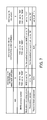
- FIG. 7 illustrates formats for downlink SPS activation and release
- FIG. 8 illustrates formats for uplink SPS activation and release
- FIG. 9 illustrates operation of downlink SPS services
- FIG. 10 illustrates formats for downlink SPS activation and release
- FIG. 11 illustrates formats for uplink SPS activation and release
- FIG. 12 illustrates a hardware configuration example of a wireless terminal
- FIG. 13 illustrates a hardware configuration example of a base station
- FIG. 14 is a block diagram of the wireless terminal
- FIG. 15 is a block diagram of the base station
- FIG. 16 is a flowchart illustrating downlink SPS operation of the base station
- FIG. 17 is a flowchart illustrating downlink SPS operation of the wireless terminal
- FIG. 18 is a flowchart illustrating downlink SPS operation of a base station according to a third embodiment
- FIG. 19 is a flowchart illustrating downlink SPS operation of a wireless terminal according to the third embodiment.
- FIG. 20 illustrates carrier aggregation
- FIG. 21 illustrates cross-carrier scheduling
- FIG. 22 illustrates formats for downlink SPS activation and release according to a fourth embodiment
- FIG. 23 illustrates formats for uplink SPS activation and release according to the forth embodiment
- FIG. 24 is a flowchart illustrating downlink SPS operation of a base station according to a fourth embodiment
- FIG. 25 is a flowchart illustrating downlink SPS operation of a wireless terminal according to the fourth embodiment.
- FIG. 26 is a flowchart illustrating downlink SPS operation of a base station according to a fifth embodiment
- FIG. 27 is a flowchart illustrating downlink SPS operation of a wireless terminal according to the fifth embodiment
- FIG. 28 is a flowchart illustrating downlink SPS operation of a base station according to a sixth embodiment.
- FIG. 29 is a flowchart illustrating downlink SPS operation of a wireless terminal according to the sixth embodiment.
- FIG. 1 illustrates a wireless communication system according to a first embodiment.
- the wireless communication system includes a wireless terminal 1 and a base station 2 .
- the wireless terminal 1 includes a communicating unit 1 a and a communication control unit 1 b
- the base station 2 includes a communicating unit 2 a and a communication control unit 2 b.
- the communicating unit 2 a of the base station 2 performs a plurality of periodic communication services with the wireless terminal 1 .
- the communicating unit 2 a is capable of performing a plurality of SPS services with the wireless terminal 1 .
- the communicating unit 2 a is capable of establishing three SPS services with the wireless terminal 1 and communicating data having a different attribute in each of the three SPS services.
- the communication control unit 2 b includes, in a control channel, service identifying information for distinguishing the plurality of periodic communication services of the communicating unit 2 a one from the other to thereby allow the wireless terminal 1 to control at least one of activation and release of each of the periodic communication services.
- the control channel is, for example, the PDCCH.
- the PDCCH includes, for example, a 3-bit field for managing a Hybrid Automatic Repeat Request (HARQ) process number.
- HARQ Hybrid Automatic Repeat Request
- the 3-bit field of the HARQ process number is usually set to ‘000’.
- the communication control unit 2 b uses the 3-bit HARQ process number field as a bitmap. Each of the three bits is associated with one of the three SPS services to thereby distinguish the three SPS services one from the other.
- the communication control unit 2 b sets the HARQ process number field of the PDCCH to ‘001’.
- the communication control unit 2 b sets the HARQ process number field of the PDCCH to ‘110’.
- the communication control unit 2 b sets the HARQ process number field of the PDCCH to ‘101’.
- the communicating unit 1 a of the wireless terminal 1 performs a plurality of periodic communication services with the base station 2 .
- the communicating unit 1 a is capable of performing a plurality of SPS services with the base station 2 .
- the communicating unit 1 a is capable of establishing three SPS services with the base station 2 and communicating data having a different attribute in each of the three SPS services.
- the communication control unit 1 b controls at least one of activation and release of each of the periodic communication services of the communicating unit 1 a according to the service identifying information included in a control channel transmitted from the base station 2 .
- the control channel is, for example, the PDCCH as mentioned above.
- the PDCCH includes a 3-bit field for managing a HARQ process number. Assume here that the three SPS services SPS1 to SPS3 are established between the wireless terminal 1 and the base station 2 in the above example. In this situation, if, for example, the HARQ process number field of the PDCCH received from the base station 2 has been set to ‘001’, the communication control unit 1 b activates SPS1. If, for example, the HARQ process number field of the received PDCCH has been set to ‘110’, the communication control unit 1 b activates SPS2 and SPS3. If, for example, the HARQ process number of the received PDCCH has been set to ‘101’, the communication control unit 1 b activates SPS1 and SPS3.
- the communication control unit 2 b of the base station 2 is configured to include, in a control channel, service identifying information for distinguishing a plurality of periodic communication services of the communicating unit 2 a to thereby allow the wireless terminal 1 to control at least one of activation and release of the individual periodic communication services.
- the communication control unit 1 b of the wireless terminal 1 is configured to control at least one of activation and release of the individual periodic communication services of the communicating unit 1 a according to the service identifying information included in the control channel transmitted from the base station 2 . In this manner, the wireless terminal 1 and the base station 2 are able to control the plurality of periodic communication services.
- FIG. 2 illustrates a wireless communication system according to the second embodiment.
- the wireless communication system includes a wireless terminal 10 and a base station 20 .
- the wireless terminal 10 is, for example, a mobile phone.
- the wireless terminal 10 and the base station 20 wirelessly communicate with each other, for example, using the LTE.
- the wireless terminal 10 and the base station 20 perform a plurality of periodic communication services.
- the wireless terminal 10 and the base station 20 establish a plurality of SPS services, and transmit and receive data having a different attribute to and from each other in each of the SPS services.
- the base station 20 transmits, to the wireless terminal 10 , image data in SPS1 and audio data in SPS2. SPS services will be explained next before the descriptions of the wireless terminal 10 and the base station 20 are given.
- FIG. 3 illustrates operation of SPS transmissions.
- FIG. 3 depicts the operation of downlink SPS transmissions.
- the dotted line arrows in FIG. 3 represent a time passage and each black square represents timing of data transmission from an evolved NodeB (eNB) to user equipment (UE).
- eNB evolved NodeB
- UE user equipment
- SPS is used for real-time communication such as VoIP.
- data is transmitted periodically, for example every 20 ms, from the eNB to the UE.
- FIG. 4 illustrates activation and release of an SPS service.
- ‘L1’ to ‘L3’ in FIG. 4 represent layers between the eNB and the UE.
- ‘L1’ is the physical layer designed to perform a range of processes, such as multiplexing of signals, channel coding, and modulation.
- ‘L2’ is the Medium Access Control (MAC) layer which provides data transmission services, such as transport channels and logical channels.
- ‘L3’ is the Radio Link Control (RLC) layer designed to provide, for example, an RRC connection process.
- MAC Medium Access Control
- RLC Radio Link Control
- the eNB informs in advance the UE of communication periodicity in an RRC connection at L3, as indicated by an arrow A11. Then, at the start of the actual SPS service, the eNB transmits an activation command to the UE through the PDCCH at L1, as indicated by an arrow A12.
- the PDCCH carrying the activation command includes information on radio resources to be used for the SPS service.
- the radio resource information included in the PDCCH is, for example, a data coding rate, a modulation scheme, and resource blocks (RB) to be used.
- the eNB transmits data in the first SPS period.
- the UE receives the data in the first SPS period together with the activation command.
- the eNB and the UE perform SPS data communication at the communication periodicity given in advance, as indicated by the black squares in FIG. 4 .
- the eNB does not transmit downlink assignments on the PDCCH in the communication after the transmission of the activation command, thus reducing the signaling overhead of the PDCCH.
- the eNB transmits a release command to the UE through the PDCCH at L1, as indicated by an arrow A13.
- the UE is able to attempt empty transmission as multiple times as indicated by a parameter called ‘implicit Release After’. With this, the SPS service is implicitly released when the number of empty transmissions reaches the value.
- the eNB transmits an activation command again to the UE to assign radio resources to be used. With this, the eNB and the UE resume the SPS service at communication periodicity previously given by the eNB.
- the above description is directed to downlink SPS activation and release, however, activation and release of an uplink SPS service is implemented in the same manner.
- the eNB informs in advance the UE of SPS communication periodicity.
- the eNB transmits an activation command to the UE.
- the eNB and the UE perform SPS data communication at the communication periodicity given in advance.
- the eNB does not transmit uplink grants on the PDCCH in the communication after the transmission of the activation command, thus reducing the signaling overhead of the PDCCH.
- FIG. 5 illustrates HARQ operation for a downlink SPS service.
- the UE when receiving data from the eNB, the UE returns an ACK or NACK indicating a data reception result to the eNB in 4 ms.
- the eNB When receiving a NACK from the UE, the eNB retransmits data corresponding to the NACK in a given period of time, as indicated by an arrow 14 of FIG. 5 .
- the eNB is able to assign radio resources for the data to be retransmitted on the PDCCH.
- FIG. 6 illustrates HARQ operation for an uplink SPS service.
- the eNB when receiving data from the UE, the eNB returns an ACK or NACK indicating a data reception result to the UE in 4 ms.
- the UE When receiving a NACK from the eNB, the UE retransmits data corresponding to the NACK in 4 ms, as indicated by arrows A15 and A16 of FIG. 6 .
- FIG. 7 illustrates formats for downlink SPS resource activation and release.
- the PDCCH carries Downlink Control Information (DCI) which has different formats for information sent to define resource allocations.
- DCI Downlink Control Information
- DCI format 1/1A is used for activation of an SPS service when Multi-Input Multi-Output (MIMO) is not applied.
- DCI format 2/2A/2B/2C is used for activation of an SPS service when MIMO is applied.
- DCI format 1A is used for release of an SPS service for both the cases where MIMO is applied and not applied.
- the eNB uses PDCCH DCI format 1/1A.
- the eNB sets individual fields on the PDCCH as indicated in the column of ‘DCI format 1/1A’ of FIG. 7 . That is, for example, a field of New Data Indicator (NDI) is set to ‘0’.
- NDI New Data Indicator
- FDD Frequency Division Duplex
- TDD Time Division Duplex
- a 4-bit field of the HARQ process number is set to ‘0000’.
- the most significant bit is set to ‘0’, and the lower 4 bits are set to indicate a modulation scheme and a coding rate for the downlink SPS service.
- a field of redundancy version is set to ‘00’, and resource blocks to be used for the downlink SPS service are set in a field of resource block assignment.
- a PDCCH may be transmitted specifically to a particular UE.
- the eNB When transmitting a UE-specific PDCCH, the eNB masks cyclic redundancy checking (CRC) of the PDCCH with an identifier called an SPS cell radio network temporary identifier (SPS-CRNTI).
- SPS-CRNTIs are identifiers assigned by the eNB to individual UEs located in the cell of the eNB to uniquely identify the UEs.
- the UE uses the SPS-CRNTI given by the eNB to de-mask the CRC. Then, the UE decodes the received PDCCH to determine a DCI format of the PDCCH. In the case where the decoded format is DCI format 1/1A and the fields on the PDCCH are set as indicated in the column of ‘DCI format 1/1A’ of FIG. 7 , the UE activates a corresponding SPS service.
- the eNB sets the fields in PDCCH DCI format 1/1A as indicated in the column of ‘DCI format 1/1A’ of FIG. 7 .
- a PDCCH DCI format received from the eNB is DCI format 1/1A and the fields on the PDCCH are set as indicated in the column of ‘DCI format 1/1A’ of FIG. 7 , the UE activates a corresponding SPS service.
- the eNB uses PDCCH DCI format 2/2A/2B/2C.
- the eNB sets individual fields on the PDCCH as indicated in the column of ‘DCI format 2/2A/2B/2C’ of FIG. 7 .
- the UE de-masks a CRC of the received PDCCH using an SPS-CRNTI and decodes the received PDCCH to determine a DCI format of the PDCCH.
- the UE activates a corresponding SPS service.
- the eNB uses PDCCH DCI format 1A regardless of MIMO being applied or not. In this case, the eNB sets individual fields on the PDCCH as indicated in the column of ‘DCI format 1A’ of FIG. 7 .
- the UE de-masks a CRC of the received PDCCH using an SPS-CRNTI and decodes the received PDCCH to determine a DCI format of the PDCCH.
- the decoded format is DCI format 1A and the fields on the PDCCH are set as indicated in the column of ‘DCI format 1A’ of FIG. 7 , the UE releases a corresponding SPS service.
- FIG. 8 illustrates formats for uplink SPS activation and release. As illustrated in FIG. 8 , in order to activate an uplink SPS service, PDCCH DCI format 0 is used regardless of MIMO being applied or not. In addition, in order to release an uplink SPS service, PDCCH DCI format 0 is used regardless of MIMO being applied or not.
- the eNB uses PDCCH DCI format 0.
- the eNB sets individual fields on the PDCCH as indicated in the column of ‘DCI format 0’ on the left side of FIG. 8 . That is, for example, the NDI field is set to ‘0’, a field of transmission power control (TPC) command for scheduled Physical Uplink Shared Channel (PUSCH) is set to ‘00’, and a field of cyclic shift demodulation reference signal (DM RS) is set to ‘000’.
- TPC transmission power control
- PUSCH Physical Uplink Shared Channel
- DM RS field of cyclic shift demodulation reference signal
- the MSB is set to ‘0’, and the lower 4 bits are set to indicate a modulation scheme and a coding rate for the uplink SPS service.
- resource blocks to be used for the uplink SPS service are set in a field of resource block assignment and hopping resource allocation.
- the UE de-masks a CRC of the received PDCCH using an SPS-CRNTI and decodes the received PDCCH to determine a DCI format of the PDCCH.
- the decoded format is DCI format 0 and the fields on the PDCCH are set as indicated in the column of ‘DCI format 0’ on the left side of FIG. 8 , the UE activates a corresponding SPS service.
- the eNB For release of an uplink SPS service, the eNB also uses PDCCH DCI format 0. In this case, the eNB sets individual fields on the PDCCH as indicated in the column of ‘DCI format 0’ on the right side of FIG. 8 .
- the UE de-masks a CRC of the received PDCCH using an SPS-CRNTI and decodes the received PDCCH to determine a DCI format of the PDCCH.
- the decoded format is DCI format 0 and the fields on the PDCCH are set as indicated in the column of ‘DCI format 0’ on the right side of FIG. 8 , the UE releases a corresponding SPS service.
- the wireless terminal 10 and the base station 20 are described next.
- the wireless terminal 10 and the base station 20 establish, for example, a plurality of SPS services to perform a plurality of periodic communication services, as described in FIG. 2 .
- FIG. 9 illustrates operation of downlink SPS services.
- the base station 20 performs two downlink SPS services, SPS1 and SPS2.
- the base station 20 first informs the wireless terminal 10 of communication periodicities of SPS1 and SPS2 when an RRC connection is established at L3, as indicated by arrows A21 and A22.
- the base station 20 is capable of using different communication periodicities for SPS1 and SPS2, however, the base station 20 uses the same periodicity according to the example of FIG. 9 .
- the base station 20 transmits activation commands to the wireless terminal 10 through the PDCCH at L1, as indicated by arrows A23 and A24.
- the base station 20 uses the HARQ process number field in PDCCH DCI format 1/1A to distinguish SPS1 from SPS2, and causes SPS1 and SPS2 to be activated separately. A more detailed description is provided later.
- the base station 20 uses the HARQ process number field in PDCCH DCI format 2/2A/2B/2C to distinguish SPS1 from SPS2, and causes SPS1 and SPS2 to be activated separately. That is, the base station 20 is able to cause only SPS1, or only SPS2, to be activated.
- the base station 20 transmits a release command to the wireless terminal 10 through the PDCCH at L1, as indicated by an arrow A25.
- the base station 20 uses the HARQ process number field in PDCCH DCI format 1A, regardless of MIMO being applied or not, to distinguish SPS1 from SPS2, and causes SPS1 and SPS2 to be released separately.
- the base station 20 is able to cause only SPS1, or only SPS2, to be released. A more detailed description is provided later.
- the base station 20 is also capable of causing SPS2 to be resumed after SPS2 is once released. As described above, the base station 20 is able to cause SPS1 and SPS2 to be activated separately. Therefore, the base station 20 is able to, for example, cause SPS2 having been once released to be reactivated separately to thereby resume SPS2.
- the base station 20 transmits image data and audio data to the wireless terminal 10 using SPS1 and SPS2, respectively.
- image data is thinned out while audio data continues to be transmitted. Therefore, if wireless channel quality degrades, for example, the base station 20 causes SPS1 transmitting image data to be released while allowing SPS2 to continue transmitting audio data. Then, when the wireless channel quality becomes better again, the base station 20 causes SPS1 to be reactivated.
- the base station 20 is also capable of causing a plurality of uplink SPS services to be activated and released, as in the case of downlink SPS services described above.
- the base station 20 performs two uplink SPS services, SPS1 and SPS2.
- the base station 20 first informs the wireless terminal 10 of communication periodicities of SPS1 and SPS2 when an RRC connection is established at L3.
- the base station 20 is capable of using different communication periodicities for SPS1 and SPS2.
- the base station 20 transmits activation commands to the wireless terminal 10 through the PDCCH at L1. Regardless of MIMO being applied or not applied, the base station 20 uses the cyclic shift DM RS field in PDCCH DCI format 0 to distinguish SPS1 from SPS2, and causes SPS1 and SPS2 to be activated separately. For example, the base station 20 is able to cause only SPS1, or only SPS2, to be activated. A more detailed description is provided later.
- the base station 20 transmits a release command to the wireless terminal 10 through the PDCCH at L1.
- the base station 20 uses the cyclic shift DM RS field in PDCCH DCI format 0, regardless of MIMO being applied or not, to distinguish SPS1 from SPS2, and causes SPS1 and SPS2 to be released separately.
- the base station 20 is able to cause only SPS1, or only SPS2, to be released. A more detailed description is provided later.
- FIG. 10 illustrates formats for downlink SPS activation and release.
- FIG. 10 differs from FIG. 7 in including an SPS Index field in place of the HARQ process number field.
- the base station 20 uses (redefines) the HARQ process number field as the SPS Index field to thereby specify a plurality of downlink SPS services.
- the base station 20 uses the 3-bit field of the HARQ process number as a bitmap to distinguish three SPS services.
- the base station 20 causes activation and release of the individual SPS services using the SPS Index.
- the base station 20 informs the wireless terminal 10 of, for example, communication periodicities of the three SPS services, SPS1 to SPS3, when an RRC connection is established. In this case, the base station 20 then transmits an activation command to the wireless terminal 10 with PDCCH DCI format 1/1A.
- the individual fields in PDCCH DCI format 1/1A are set by the base station 20 as indicated in the column of ‘DCI format 1/1A’ of FIG. 10 .
- the base station 20 specifies one or more SPS services to be activated using the 3-bit bitmap of the SPS Index.
- each bit of the 3-bit bitmap corresponds to one of SPS1 to SPS3, and the SPS Index is denoted as (b2, b1, b0) where ‘b0’ corresponds to SPS1, ‘b1’ corresponds to SPS2, and ‘b2’ corresponds to SPS3.
- the base station 20 sets ‘001’ in the SPS Index field.
- SPS2 and SPS3 to be activated
- the base station 20 sets ‘110’ in the SPS Index field. In this manner, the base station 20 is able to cause only SPS1, or only SPS2 and SPS3, to be activated.
- the base station 20 is able to specify one or more of SPS1 to SPS3 to be activated, as described above, using the SPS Index of PDCCH DCI format 2/2A/2B/2C.
- the base station 20 is able to specify one or more of SPS1 to SPS3 to be released using the SPS Index of DCI format 1A.
- the 4-bits field of the HARQ process number may be used as the SPS Index.
- the 3-bit field of the HARQ process number is preferable to use the 3-bit field of the HARQ process number as the SPS Index. That is, the SPS Index represented by the 3-bit field of the HARQ process number enables its use in both FDD and TDD operation.
- FIG. 11 illustrates formats for uplink SPS activation and release.
- FIG. 11 differs from FIG. 8 in including the SPS Index field in place of the cyclic shift DM RS field.
- the base station 20 uses the cyclic shift DM RS field as the SPS Index field to thereby specify a plurality of uplink SPS services.
- the base station 20 uses the 3-bit field of the cyclic shift DM RS as a bitmap to distinguish three SPS services.
- the base station 20 causes activation and release of the individual SPS services using the SPS Index.
- the base station 20 informs the wireless terminal 10 of communication periodicities of the three SPS services, SPS1 to SPS3, when an RRC connection is established. In this case, regardless of MIMO being applied or not, the base station 20 then transmits an activation command to the wireless terminal 10 with PDCCH DCI format 0.
- the individual fields in PDCCH DCI format 0 are set by the base station 20 as indicated in the column of ‘DCI format 0’ on the left side of FIG. 11 .
- the base station 20 specifies one or more SPS services to be activated using the 3-bit bitmap of the SPS Index.
- each bit of the 3-bit bitmap corresponds to one of SPS1 to SPS3, and the SPS Index is denoted as (b2, b1, b0) where ‘b0’ corresponds to SPS1, ‘b1’ corresponds to SPS2, and ‘b2’ corresponds to SPS3.
- the base station 20 sets ‘001’ in the SPS Index field.
- SPS2 and SPS3 to be activated
- the base station 20 sets ‘110’ in the SPS Index field. In this manner, the base station 20 is able to cause only SPS1, or only SPS2 and SPS3, to be activated.
- the base station 20 is able to specify one or more of SPS1 to SPS3 to be released, as described above, using the SPS Index of DCI format 0.
- FIG. 12 illustrates a hardware configuration example of a wireless terminal.
- the wireless terminal 10 includes a processor 31 , a main memory 32 , a read-only memory (ROM) 33 , a storage 34 , a communication interface 35 , an input-output device 36 , a display 37 , and a bus 38 .
- the main memory 32 , the ROM 33 , the storage 34 , the communication interface 35 , the input-output device 36 , and the display 37 are connected to the processor 31 via the bus 38 .
- Overall control of the wireless terminal 10 is exercised by the processor 31 .
- the processor 31 is, for example, a central processing unit (CPU).
- the main memory 32 temporarily stores therein data and programs to be used by the processor 31 for its various processes.
- the ROM 33 stores therein static information such as protocols to define operation of the wireless terminal 10 .
- the ROM 33 stores information used by the processor 31 to implement data plane processing, control plane processing, scheduling processing, and the like.
- the storage 34 stores therein data and programs to be used by the processor 31 for its various processes.
- the communication interface 35 wirelessly communicates with the base station 20 .
- the communication interface 35 converts baseband signals into radio frequency signals, which are then output to an antenna (not illustrated).
- the communication interface 35 also frequency-converts radio signals received by an antenna (not illustrated) into baseband signals.
- the input-output device 36 includes, for example, keys, speakers, and a microphone.
- the keys allow a user to input letters and numbers into the wireless terminal 10 .
- the speakers convert audio signals received from the base station 20 into sound to output.
- the microphone converts voice of the user into electrical signals.
- the display 37 is, for example, a liquid crystal display (LCD).
- the display 37 displays, for example, data received from the base station 20 .
- FIG. 13 illustrates a hardware configuration example of a base station.
- the base station 20 includes a processor 41 , a main memory 42 , a ROM 43 , a storage 44 , a communication interface 45 , and a bus 46 .
- the main memory 42 , the ROM 43 , the storage 44 , and the communication interface 45 are connected to the processor 41 via the bus 46 .
- Overall control of the base station 20 is exercised by the processor 41 which is, for example, a CPU.
- the main memory 42 temporarily stores therein data and programs to be used by the processor 41 for its various processes.
- the ROM 43 stores therein static information such as protocols to define operation of the base station 20 .
- the ROM 43 stores information used by the processor 41 to implement data plane processing, control plane processing, scheduling processing, and the like.
- the storage 44 stores therein data and programs to be used by the processor 41 for its various processes.
- the communication interface 45 wirelessly communicates with the wireless terminal 10 .
- the communication interface 45 converts baseband signals into radio frequency signals, which are then output to an antenna (not illustrated).
- the communication interface 45 also frequency-converts radio signals received by an antenna (not illustrated) into baseband signals.
- the communication interface 45 communicates with a higher-level apparatus, such as a serving gateway (S-GW), using a wired connection.
- S-GW serving gateway
- FIG. 14 is a block diagram of a wireless terminal.
- the wireless terminal 10 includes a transmitting and receiving unit 51 , an uplink transmitting unit 52 , and a control unit 53 .
- the control unit 53 includes a data plane unit 54 and a control plane unit 55 .
- the data plane unit 54 includes an SPS transmission managing unit 54 a and a HARQ managing unit 54 b .
- the control plane unit 55 includes an SPS periodicity control unit 55 a and an SPS communication control unit 55 b .
- Functions of the transmitting and receiving unit 51 and the uplink transmitting unit 52 are implemented, for example, by the communication interface 35 of FIG. 12 .
- Functions of the control unit 53 are implemented, for example, by the processor 31 of FIG. 12 .
- the transmitting and receiving unit 51 transmits and receives data wirelessly.
- the uplink transmitting unit 52 performs uplink data transmission processes, such as acknowledgment of transmitted data.
- the data plane unit 54 provides various controls on the physical layer, the MAC layer, the RLC layer, and the Packet Data Control Protocol (PDCP) layer.
- the SPS transmission managing unit 54 a manages data transmission timing of a plurality of SPS services.
- the HARQ managing unit 54 b is in charge of HARQ management for data.
- the control plane unit 55 executes processes of the RRC protocol, and also controls all the layers.
- the SPS periodicity control unit 55 a controls periodicities of a plurality of SPS services individually.
- the SPS communication control unit 55 b controls timing of transmitting and receiving data of the individual SPS services and their radio resources.
- FIG. 15 is a block diagram of a base station.
- the base station 20 includes transmitting and receiving units 61 and 63 , a scheduling unit 62 , and a control unit 64 .
- the control unit 64 includes a data plane unit 65 and a control plane unit 66 .
- the data plane unit 65 includes an SPS transmission managing unit 65 a and a HARQ managing unit 65 b .
- the control plane unit 66 includes an SPS periodicity control unit 66 a and an SPS communication control unit 66 b .
- Functions of the transmitting and receiving units 61 and 63 are implemented, for example, by the communication interface 45 of FIG. 13 .
- Functions of the scheduling unit 62 and the control unit 64 are implemented, for example, by the processor 41 of FIG. 13 .
- the transmitting and receiving unit 61 transmits and receives data wirelessly.
- the scheduling unit 62 allocates (schedules) radio resources for data to be transmitted wirelessly.
- the transmitting and receiving unit 63 transmits and receives data to and from a higher-level apparatus.
- the data plane unit 65 provides various controls on the physical layer, the MAC layer, the RLC layer, and the PDCP layer.
- the SPS transmission managing unit 65 a manages data transmission timing of a plurality of SPS services.
- the HARQ managing unit 65 b is in charge of HARQ management for data.
- the control plane unit 66 executes processes of the RRC protocol, and also controls all the layers.
- the SPS periodicity control unit 66 a controls periodicities of a plurality of SPS services individually.
- the SPS communication control unit 66 b controls timing of transmitting and receiving data of the individual SPS services and their radio resources.
- FIG. 16 is a flowchart illustrating downlink SPS operation of a base station.
- the SPS periodicity control unit 66 a of the base station 20 configures communication periodicities of a plurality of SPS services individually. For example, to perform video communication, the SPS periodicity control unit 66 a configures SPS periodicity of image data and SPS periodicity of audio data individually. When an RRC connection is established, the SPS communication control unit 66 b transmits the periodicities of the SPS services configured by the SPS periodicity control unit 66 a to the wireless terminal 10 via the transmitting and receiving unit 61 .
- the SPS communication control unit 66 b causes one or more SPS services to be activated in order to start the SPS services.
- the SPS communication control unit 66 b specifies the SPS services to be activated using the SPS Index of the PDCCH. For example, to specify the SPS services to be activated, the SPS communication control unit 66 b uses the 3-bit bitmap of the SPS Index.
- the transmitting and receiving unit 61 transmits, to the wireless terminal 10 , the PDCCH carrying an activation command generated by the SPS communication control unit 66 b . Note that, when transmitting the PDCCH with the activation command, the transmitting and receiving unit 61 also transmits data in the first SPS period to the wireless terminal 10 through the PDSCH.
- Step S 3 The SPS transmission managing unit 65 a determines whether it is time to transmit data of one of the activated SPS services, based on the communication periodicities configured by the SPS periodicity control unit 66 a . If determining that it is time to transmit data of one of the activated SPS services, the SPS transmission managing unit 65 a proceeds to step S 4 . On the other hand, if determining that it is not time to transmit data of one of the activated SPS services, the SPS transmission managing unit 65 a repeats the determination process of step S 3 .
- Step S 4 The transmitting and receiving unit 61 transmits data of the corresponding one of the activated SPS services to the wireless terminal 10 .
- the SPS communication control unit 66 b determines whether to cause an SPS service to be released.
- the SPS communication control unit 66 b determines an SPS service to be released, for example, based on the state of the radio channel. Specifically, if the state of the radio channel drops below a threshold value, the SPS communication control unit 66 b determines release of an SPS service dealing with image data transmission to thin out image data. If determining release of an SPS service, the SPS communication control unit 66 b proceeds to step S 6 . On the other hand, if determining not to release an SPS service, the SPS communication control unit 66 b proceeds to step S 3 .
- the SPS communication control unit 66 b specifies the SPS service to be released using the SPS Index of the PDCCH. For example, to specify the SPS service to be released, the SPS communication control unit 66 b uses the bitmap of the SPS Index.
- the transmitting and receiving unit 61 transmits a release command generated by the SPS communication control unit 66 b to the wireless terminal 10 .
- FIG. 17 is a flowchart illustrating downlink SPS operation of a wireless terminal.
- Step S 11 When an RRC connection is established, the SPS communication control unit 55 b of the wireless terminal 10 receives communication periodicities of SPS services from the base station 20 via the transmitting and receiving unit 51 .
- the SPS periodicity control unit 55 a configures the communication periodicities received by the transmitting and receiving unit 51 as SPS communication periodicities.
- the SPS periodicity control unit 55 a stores the received communication periodicities in a memory for managing communication periodicities of a plurality of SPS services.
- the SPS communication control unit 55 b receives an activation command from the base station 20 via the transmitting and receiving unit 51 . Based on the received activation command, the SPS communication control unit 55 b activates one or more SPS services individually. For example, the SPS communication control unit 55 b determines the SPS services to be activated based on the 3-bit bitmap of the SPS Index. Note that, when receiving the PDCCH carrying the activation command, the transmitting and receiving unit 51 receives data in the first SPS period through the PDSCH.
- Step S 13 The SPS transmission managing unit 54 a determines whether it is time to receive data of one of the activated SPS services, based on the communication periodicities configured by the SPS periodicity control unit 55 a . If determining that it is time to receive data of one of the activated SPS services, the SPS transmission managing unit 54 a proceeds to step S 14 . On the other hand, if determining that it is not time to receive data of one of the activated SPS services, the SPS transmission managing unit 54 a repeats the determination process of step S 13 .
- Step S 14 The transmitting and receiving unit 51 receives data of the corresponding one of the activated SPS services transmitted from the base station 20 .
- Step S 15 The SPS communication control unit 55 b determines whether a release command has been received via the transmitting and receiving unit 51 . If a release command has not been received via the transmitting and receiving unit 51 , the SPS communication control unit 55 b proceeds to step S 13 . On the other hand, if a release command has been received via the transmitting and receiving unit 51 , the SPS communication control unit 55 b proceeds to step S 16 .
- Step S 16 The SPS communication control unit 55 b releases an SPS service specified by the release command.
- the SPS service to be released is indicated by the 3-bit bitmap of the SPS Index.
- the SPS periodicity control unit 66 a of the base station 20 configures communication periodicities of uplink SPS services.
- the SPS communication control unit 66 b informs the wireless terminal 10 , via the transmitting and receiving unit 61 , of communication periodicities configured by the SPS periodicity control unit 66 a.
- the SPS communication control unit 55 b of the wireless terminal 10 receives the communication periodicities of uplink SPS services via the transmitting and receiving unit 51 .
- the SPS periodicity control unit 55 a configures the received communication periodicities as SPS communication periodicities.
- the SPS communication control unit 66 b of the base station 20 specifies one or more of the uplink SPS services to be started using the SPS Index to thereby cause the uplink SPS services to be activated.
- the transmitting and receiving unit 61 transmits, to the wireless terminal 10 , the PDCCH carrying an activation command generated by the SPS communication control unit 66 b.
- the communication control unit 55 b of the wireless terminal 10 receives the activation command from the base station 20 via the transmitting and receiving unit 51 . Based on the received activation command, the SPS communication control unit 55 b activates one or more of the uplink SPS services individually.
- the SPS transmission managing unit 54 a transmits, to the base station 20 , data of each of the activated SPS services based on the communication periodicities configured by the SPS periodicity control unit 55 a .
- the transmitting and receiving unit 61 of the base station 20 receives the data of the individual SPS services transmitted from the wireless terminal 10 .
- the SPS communication control unit 66 b of the base station 20 specifies the SPS service to be released using the SPS Index of the PDCCH.
- the SPS communication control unit 55 b of the wireless terminal 10 releases the SPS service specified by a release command received via the transmitting and receiving unit 51 . With this, the transmitting and receiving unit 51 stops or ends the specified SPS service.
- the SPS communication control unit 66 b of the base station 20 includes, in the PDCCH, the SPS Index for distinguishing a plurality of SPS services one from the other to thereby allow the wireless terminal 10 to control activation of the SPS services individually. Then, the communication control unit 55 b of the wireless terminal 10 controls activation of the individual SPS services based on the SPS Index of the PDCCH transmitted from the base station 20 . This enables the wireless terminal 10 and the base station 20 to control the plurality of SPS services, with reduced signaling overhead.
- the SPS communication control unit 55 b of the wireless terminal 10 and the SPS communication control unit 66 b of the base station 20 control activation and release of individual SPS services, using the PDCCH DCI format, the field values of the PDCCH, and the SPS Index. This enables the wireless terminal 10 and the base station 20 to start and stop the plurality of SPS services, with reduced signaling overhead.
- a third embodiment is described next in detail with reference to the accompanying drawings.
- the bitmap of the SPS Index is used to distinguish SPS services one from the other.
- the third embodiment distinguishes SPS services using a bit value (binary number) of the SPS Index.
- the wireless communication system of the third embodiment is the same as the one illustrated in FIG. 2 .
- PDCCH DCI formats are the same as those of FIGS. 10 and 11 .
- each SPS service is distinguished by a bit value of the SPS Index.
- the hardware configuration examples of the wireless terminal and the base station of the third embodiment are the same as those in FIGS. 12 and 13 , respectively.
- the block diagrams of the wireless terminal and the base station of the third embodiment are the same as those in FIGS. 14 and 15 , respectively. Note however that the third embodiment differs from the second embodiment in how the SPS communication control units 55 b and 66 b distinguish SPS services. According to the third embodiment, the SPS communication control units 55 b and 66 b distinguish SPS services using the bit value of the SPS Index.
- the SPS Index is 3-bit wide as in the case of FIGS. 10 and 11 .
- the SPS communication control units 55 b and 66 b use the 3-bit value of the SPS Index.
- eight SPS services may be distinguished. For example, the SPS Index with ‘000’ indicates SPS1, the SPS Index with ‘001’ indicates SPS2, . . . , and the SPS Index with ‘111’ indicates SPS8.
- the SPS communication control unit 66 b of the base station 20 sets the SPS Index of PDCCH DCI format 1/1A or PDCCH DCI format 2/2A/2B/2C to ‘101’. Since the SPS Index of the received PDCCH DCI format 1/1A or PDCCH DCI format 2/2A/2B/2C is ‘101’, the communication control unit 55 b of the wireless terminal 10 activates SPS6.
- the SPS communication control units 55 b and 66 b In order to release a downlink SPS service, the SPS communication control units 55 b and 66 b also use a bit value of the SPS Index to specify the SPS service to be released in the same manner. In addition, as for activation and release of an uplink SPS service, the SPS communication control units 55 b and 66 b use a bit value of the SPS Index to specify the SPS service in the same manner.
- the SPS communication control units 55 b and 66 b control activation or release of a plurality of SPS services using one PDCCH. For example, by setting the SPS Index of the PDCCH to ‘011’, the SPS communication control units 55 b and 66 b are able to activate or release both SPS1 and SPS2.
- the SPS communication control units 55 b and 66 b transmit and receive a PDCCH for each SPS service to be activated or released.
- the SPS communication control units 55 b and 66 b control activation or release of SPS1 and SPS2.
- the SPS communication control units 55 b and 66 b transmit and receive a PDCCH in which the SPS Index is set to ‘000’.
- the SPS communication control units 55 b and 66 b transmit and receive a PDCCH in which the SPS Index is set to ‘001’. With this, SPS1 and SPS2 are activated or released.
- FIG. 18 is a flowchart illustrating downlink SPS operation of a base station according to the third embodiment.
- the SPS periodicity control unit 66 a of the base station 20 configures communication periodicities of a plurality of SPS services individually. For example, to perform video communication, the SPS periodicity control unit 66 a configures SPS periodicity of image data and SPS periodicity of audio data individually. When an RRC connection is established, the SPS communication control unit 66 b transmits the periodicities of the SPS services configured by the SPS periodicity control unit 66 a to the wireless terminal 10 via the transmitting and receiving unit 61 .
- the SPS communication control unit 66 b causes one or more SPS services to be activated in order to start the SPS services.
- the SPS communication control unit 66 b specifies each of the SPS services to be activated using the SPS Index of a PDCCH. For example, to specify each of the SPS services to be activated, the SPS communication control unit 66 b uses the 3-bit value of the SPS Index.
- the transmitting and receiving unit 61 transmits, to the wireless terminal 10 , a PDCCH carrying each activation command generated by the SPS communication control unit 66 b . Note that, when transmitting the PDCCH with each activation command, the transmitting and receiving unit 61 also transmits corresponding data in the first SPS period to the wireless terminal 10 through the PDSCH.
- Step S 23 The SPS transmission managing unit 65 a determines whether it is time to transmit data of one of the activated SPS services based on the communication periodicities configured by the SPS periodicity control unit 66 a . If determining that it is time to transmit data of one of the activated SPS services, the SPS transmission managing unit 65 a proceeds to step S 24 . On the other hand, if determining that it is not time to transmit data of one of the activated SPS services, the SPS transmission managing unit 65 a repeats the determination process of step S 23 .
- Step S 24 The transmitting and receiving unit 61 transmits data of the corresponding one of the activated SPS services to the wireless terminal 10 .
- the SPS communication control unit 66 b determines whether to cause an SPS service to be released.
- the SPS communication control unit 66 b determines an SPS service to be released, for example, based on the state of the radio channel. Specifically, if the state of the radio channel drops below a threshold value, the SPS communication control unit 66 b determines release of an SPS service dealing with image data transmission to thin out image data. If determining release of an SPS service, the SPS communication control unit 66 b proceeds to step S 26 . On the other hand, if determining not to release an SPS service, the SPS communication control unit 66 b proceeds to step S 23 .
- the SPS communication control unit 66 b specifies the SPS service to be released using the SPS Index of the PDCCH. For example, to specify the SPS service to be released, the SPS communication control unit 66 b uses the 3-bit value of the SPS Index.
- the transmitting and receiving unit 61 transmits a release command generated by the SPS communication control unit 66 b to the wireless terminal 10 .
- FIG. 19 is a flowchart illustrating downlink SPS operation of a wireless terminal according to the third embodiment.
- Step S 31 When an RRC connection is established, the SPS communication control unit 55 b of the wireless terminal 10 receives communication periodicities of SPS services from the base station 20 via the transmitting and receiving unit 51 .
- the SPS periodicity control unit 55 a configures the communication periodicities received by the transmitting and receiving unit 51 as SPS communication periodicities.
- the SPS periodicity control unit 55 a stores the received communication periodicities in a memory for managing communication periodicities of a plurality of SPS services.
- the SPS communication control unit 55 b receives one or more activation commands from the base station 20 via the transmitting and receiving unit 51 . Based on the received activation commands, the SPS communication control unit 55 b activates corresponding SPS services individually. For example, the SPS communication control unit 55 b determines an SPS service to be activated based on the 3-bit value of the SPS Index of each PDCCH. Note that, when receiving a PDCCH carrying an activation command, the transmitting and receiving unit 51 receives corresponding data in the first SPS period through the PDSCH.
- Step S 33 The SPS transmission managing unit 54 a determines whether it is time to receive data of one of the activated SPS services, based on the communication periodicities configured by the SPS periodicity control unit 55 a . If determining that it is time to receive data of one of the activated SPS services, the SPS transmission managing unit 54 a proceeds to step S 34 . On the other hand, if determining that it is not time to receive data of one of the activated SPS services, the SPS transmission managing unit 54 a repeats the determination process of step S 33 .
- Step S 34 The transmitting and receiving unit 51 receives data of the corresponding one of the activated SPS services transmitted from the base station 20 .
- Step S 35 The SPS communication control unit 55 b determines whether a release command has been received via the transmitting and receiving unit 51 . If a release command has not been received via the transmitting and receiving unit 51 , the SPS communication control unit 55 b proceeds to step S 33 . On the other hand, if a release command has been received via the transmitting and receiving unit 51 , the SPS communication control unit 55 b proceeds to step S 36 .
- Step S 36 The SPS communication control unit 55 b releases an SPS service specified by the release command.
- the SPS service to be released is indicated by the 3-bit bitmap of the SPS Index of a PDCCH.
- the SPS periodicity control unit 66 a of the base station 20 configures communication periodicities of uplink SPS services.
- the SPS communication control unit 66 b informs the wireless terminal 10 , via the transmitting and receiving unit 61 , of communication periodicities configured by the SPS periodicity control unit 66 a.
- the SPS communication control unit 55 b of the wireless terminal 10 receives the communication periodicities of uplink SPS services via the transmitting and receiving unit 51 .
- the SPS periodicity control unit 55 a configures the received communication periodicities as SPS communication periodicities.
- the SPS communication control unit 66 b of the base station 20 specifies each of the uplink SPS services to be started using the SPS Index of a PDCCH to thereby cause the uplink SPS service to be activated.
- the transmitting and receiving unit 61 transmits, to the wireless terminal 10 , each PDCCH carrying an activation command generated by the SPS communication control unit 66 b.
- the communication control unit 55 b of the wireless terminal 10 receives one or more activation commands from the base station 20 via the transmitting and receiving unit 51 . Based on the received activation commands, the SPS communication control unit 55 b activates corresponding uplink SPS services individually.
- the SPS transmission managing unit 54 a transmits, to the base station 20 , data of each of the activated SPS services based on the communication periodicities configured by the SPS periodicity control unit 55 a .
- the transmitting and receiving unit 61 of the base station 20 receives the data of the individual SPS services transmitted from the wireless terminal 10 .
- the SPS communication control unit 66 b of the base station 20 specifies the SPS service to be released using the bit value of the SPS Index of a PDCCH.
- the SPS communication control unit 55 b of the wireless terminal 10 releases the SPS service specified by a release command received via the transmitting and receiving unit 51 . With this, the transmitting and receiving unit 51 stops or ends the specified SPS service.
- the SPS communication control units 55 b and 66 b use a bit value of the SPS Index to distinguish each SPS service, which enables control of a plurality of SPS services with reduced signaling overhead.
- the fourth embodiment is directed to the case where carrier aggregation is applied to a wireless communication system.
- the PDCCH includes a field called Carrier Indicator Field (CIF).
- CIF Carrier Indicator Field
- the CIF is set to ‘0’.
- the CIF with ‘0’ is used as a field for distinguishing SPS services.
- the wireless communication system according to the fourth embodiment is the same as the one illustrated in FIG. 2 .
- carrier aggregation is applied to the wireless communication system of the fourth embodiment.
- the hardware configuration examples of the wireless terminal and the base station of the fourth embodiment are the same as those in FIGS. 12 and 13 , respectively.
- the block diagrams of the wireless terminal and the base station of the fourth embodiment are the same as those in FIGS. 14 and 15 , respectively.
- the fourth embodiment differs in how the SPS communication control units 55 b and 66 b distinguish SPS services. Carrier aggregation is explained first.
- FIG. 20 is a diagram for explaining carrier aggregation.
- the horizontal axis and vertical axis of FIG. 20 represent frequency and power, respectively.
- FIG. 20 illustrates frequency bands used by the eNB and the UE.
- Carrier aggregation having been examined in LTE-A enables large amount of data transmission by aggregating a plurality of frequency bands, as illustrated in FIG. 20 .
- a serving cell performing key control, such as transmission of control signals is called ‘primary cell (PCell)’ and the remaining serving cells are called ‘secondary cells (SCell)’.
- PCell and each SCell of FIG. 20 represent a primary cell and a secondary cell, respectively.
- FIG. 21 is a diagram for explaining cross-carrier scheduling.
- Cross-carrier scheduling may be adopted for carrier aggregation.
- radio resources for transmitting a PDCCH and radio resources for a PDSCH corresponding to the PDCCH are allocated to different carriers.
- the eNB transmits a PDCCH to the UE on the PCell.
- Each PDCCH includes the CIF of 3 bits, by which the UE recognizes a SCell corresponding to the PDCCH. Assuming for example that the CIF on a PDCCH received on PCell is ‘001’, the UE recognizes that the received PDCCH is a PDCCH of SCell1.
- the CIF on the PDCCH for an SPS service is set to ‘000’.
- the CIF on the PDCCH is used to distinguish SPS services one from the other.
- FIG. 22 illustrates formats for downlink SPS activation and release according to the fourth embodiment.
- FIG. 22 differs from FIG. 7 in including the CIF.
- the base station 20 uses the CIF to specify a plurality of downlink SPS services.
- the base station 20 uses the 3-bit field of the CIF as a bitmap to distinguish three SPS services.
- the base station 20 causes activation and release of the individual SPS services using the CIF.
- the base station 20 informs the wireless terminal 10 of, for example, communication periodicities of the three SPS services, SPS1 to SPS3, when an RRC connection is established. In this case, the base station 20 then transmits an activation command to the wireless terminal 10 with PDCCH DCI format 1/1A.
- the individual fields in PDCCH DCI format 1/1A are set by the base station 20 as indicated in the column of ‘DCI format 1/1A’ of FIG. 22 .
- the base station 20 specifies one or more SPS services to be activated using the 3-bit bitmap of the CIF.
- each bit of the 3-bit bitmap corresponds to one of SPS1 to SPS3, and the CIF is denoted as (b2, b1, b0) where ‘b0’ corresponds to SPS1, ‘b1’ corresponds to SPS2, and ‘b2’ corresponds to SPS3.
- the base station 20 sets ‘001’ in the CIF.
- SPS2 and SPS3 sets ‘110’ in the CIF. In this manner, the base station 20 is able to cause only SPS1, or only SPS2 and SPS3, to be activated.
- the base station 20 is able to specify one or more of SPS1 to SPS3 to be activated, as described above, using the CIF of PDCCH DCI format 2/2A/2B/2C.
- the base station 20 is able to specify one or more of SPS1 to SPS3 to be released using the CIF of DCI format 1A.
- FIG. 23 illustrates formats for uplink SPS activation and release according to the forth embodiment.
- FIG. 23 differs from FIG. 8 in including the CIF.
- the base station 20 uses the CIF to specify a plurality of uplink SPS services.
- the base station 20 uses the 3-bit field of the CIF as a bitmap to distinguish three SPS services.
- the base station causes activation and release of the individual SPS services using the CIF.
- the base station 20 informs the wireless terminal 10 of communication periodicities of the three SPS services, SPS1 to SPS3, when an RRC connection is established. In this case, regardless of MIMO being applied or not, the base station 20 then transmits an activation command to the wireless terminal 10 with PDCCH DCI format 0.
- the individual fields in PDCCH DCI format 0 are set by the base station 20 as indicated in the column of ‘DCI format 0’ on the left side of FIG. 23 .
- the base station 20 specifies one or more SPS services to be activated using the 3-bit bitmap of the CIF.
- each bit of the 3-bit bitmap corresponds to one of SPS1 to SPS3, and the CIF is denoted as (b2, b1, b0) where ‘b0’ corresponds to SPS1, ‘b1’ corresponds to SPS2, and ‘b2’ corresponds to SPS3.
- the base station 20 sets ‘001’ in the CIF.
- SPS2 and SPS3 sets ‘110’ in the CIF. In this manner, the base station 20 is able to cause only SPS1, or only the SPS2 and SPS3, to be activated.
- the base station 20 is able to specify one or more of SPS1 to SPS3 to be released, as described above, using the CIF of DCI format 0.
- FIG. 24 is a flowchart illustrating downlink SPS operation of a base station according to the fourth embodiment.
- Step S 41 Because step S 41 is the same as step S 1 of FIG. 16 , the description is omitted.
- the SPS communication control unit 66 b causes one or more SPS services to be activated in order to start the SPS services.
- the SPS communication control unit 66 b specifies the SPS services to be activated using the CIF of the PDCCH. For example, to specify the SPS services to be activated, the SPS communication control unit 66 b uses the 3-bit bitmap of the CIF.
- the transmitting and receiving unit 61 transmits, to the wireless terminal 10 , the PDCCH carrying an activation command generated by the SPS communication control unit 66 b . Note that, when transmitting the PDCCH with the activation command, the transmitting and receiving unit 61 also transmits data in the first SPS period to the wireless terminal 10 through the PDSCH.
- Steps S 43 to S 45 Because steps S 43 to S 45 are the same as steps S 3 to S 5 of FIG. 16 , the descriptions are omitted.
- the SPS communication control unit 66 b specifies the SPS service to be released using the CIF of the PDCCH. For example, to specify the SPS service to be released, the SPS communication control unit 66 b uses the bitmap of the CIF. The transmitting and receiving unit transmits a release command generated by the SPS communication control unit 66 b to the wireless terminal 10 .
- FIG. 25 is a flowchart illustrating downlink SPS operation of a wireless terminal according to the fourth embodiment.
- Step S 51 Because step S 51 is the same as step S 11 of FIG. 17 , the description is omitted.
- the SPS communication control unit 55 b receives an activation command from the base station 20 via the transmitting and receiving unit 51 . Based on the received activation command, the SPS communication control unit 55 b activates one or more SPS services individually. For example, the SPS communication control unit 55 b determines the SPS services to be activated based on the 3-bit bitmap of the CIF. Note that, when receiving the PDCCH carrying the activation command, the transmitting and receiving unit 51 receives data in the first SPS period through the PDSCH.
- Steps S 53 to S 55 Because steps S 53 to S 55 are the same as steps S 13 to S 15 of FIG. 17 , the descriptions are omitted.
- Step S 56 The SPS communication control unit 55 b releases an SPS service specified by the release command.
- the SPS service to be released is indicated by the 3-bit bitmap of the CIF.
- uplink SPS operation is implemented in the same manner.
- the uplink SPS operation of the fourth embodiment is the same as, for example, that of the second embodiment although differing in distinguishing individual SPS services using the CIF.
- the SPS communication control units 55 b and 66 b use a bitmap of the CIF to distinguish a plurality of SPS services one from the other, which enables control of the SPS services with reduced signaling overhead.
- a fifth embodiment is described next in detail with reference to the accompanying drawings.
- the bitmap of the CIF is used to distinguish SPS services one from the other.
- the fifth embodiment distinguishes SPS services using a bit value of the CIF.
- the wireless communication system of the fifth embodiment is the same as the one illustrated in FIG. 2 .
- PDCCH DCI formats are the same as those of FIGS. 22 and 23 .
- each SPS service is distinguished by a bit value of the CIF.
- the hardware configuration examples of the wireless terminal and the base station of the fifth embodiment are the same as those in FIGS. 12 and 13 , respectively.
- the block diagrams of the wireless terminal and the base station of the fifth embodiment are the same as those in FIGS.
- the fifth embodiment differs in how the SPS communication control units 55 b and 66 b distinguish each SPS service, and the SPS communication control units 55 b and 66 b use the bit value of the CIF to distinguish each SPS service.
- the CIF is 3-bit wide as in the case of FIGS. 22 and 23 .
- the SPS communication control units 55 b and 66 b use the 3-bit value of the CIF.
- eight SPS services may be distinguished.
- the CIF with ‘000’ indicates SPS1
- the CIF with ‘001’ indicates SPS2, . . .
- the CIF with ‘111’ indicates SPS8.
- the SPS communication control unit 66 b of the base station 20 sets the CIF of PDCCH DCI format 1/1A or PDCCH DCI format 2/2A/2B/2C to ‘101’. Since the CIF of the received PDCCH DCI format 1/1A or PDCCH DCI format 2/2A/2B/2C is ‘101’, the communication control unit 55 b of the wireless terminal 10 activates SPS6.
- the SPS communication control units 55 b and 66 b In order to release a downlink SPS service, the SPS communication control units 55 b and 66 b also use a bit value of the CIF to specify the SPS service to be released in the same manner. In addition, as for activation and release of an uplink SPS service, the SPS communication control units 55 b and 66 b use a bit value of the CIF to specify the SPS service in the same manner.
- the SPS communication control units 55 b and 66 b control activation or release of a plurality of SPS services using one PDCCH. For example, by setting the CIF of the PDCCH to ‘011’, the SPS communication control units 55 b and 66 b are able to activate or release both SPS1 and SPS2.
- the SPS communication control units 55 b and 66 b transmit and receive a PDCCH for each SPS service to be activated or released.
- the SPS communication control units 55 b and 66 b control activation or release of SPS1 and SPS2.
- the SPS communication control units 55 b and 66 b transmit and receive a PDCCH in which the CIF is set to ‘000’.
- the SPS communication control units 55 b and 66 b transmit and receive a PDCCH in which the CIF is set to ‘001’. With this, SPS1 and SPS2 are activated or released.
- FIG. 26 is a flowchart illustrating downlink SPS operation of a base station according to the fifth embodiment.
- Step S 61 Because step S 61 is the same as step S 21 of FIG. 18 , the description is omitted.
- the SPS communication control unit 66 b causes one or more SPS services to be activated in order to start the SPS services.
- the SPS communication control unit 66 b specifies each of the SPS services to be activated using the CIF of a PDCCH. For example, to specify each of the SPS services to be activated, the SPS communication control unit 66 b uses the 3-bit bitmap of the CIF.
- the transmitting and receiving unit 61 transmits, to the wireless terminal 10 , a PDCCH carrying each activation command generated by the SPS communication control unit 66 b . Note that, when transmitting the PDCCH with each activation command, the transmitting and receiving unit 61 also transmits corresponding data in the first SPS period to the wireless terminal 10 through the PDSCH.
- Steps S 63 to S 65 Because steps S 63 to S 65 are the same as steps S 23 to S 25 of FIG. 18 , the descriptions are omitted.
- Step S 66 The SPS communication control unit 66 b specifies the SPS service to be released using the CIF of the PDCCH. For example, to specify the SPS service to be released, the SPS communication control unit 66 b uses the 3-bit value of the CIF.
- the transmitting and receiving unit 61 transmits a release command generated by the SPS communication control unit 66 b to the wireless terminal 10 .
- FIG. 27 is a flowchart illustrating downlink SPS operation of a wireless terminal according to the fifth embodiment.
- Step S 71 Because step S 71 is the same as step S 31 of FIG. 19 , the description is omitted.
- the SPS communication control unit 55 b receives one or more activation commands from the base station 20 via the transmitting and receiving unit 51 . Based on the received activation commands, the SPS communication control unit 55 b activates corresponding SPS services individually. For example, the SPS communication control unit 55 b determines an SPS service to be activated based on the 3-bit value of the CIF of each PDCCH. Note that, when receiving a PDCCH carrying an activation command, the transmitting and receiving unit 51 receives corresponding data in the first SPS period through the PDSCH.
- Steps S 73 to S 75 Because steps S 73 to S 75 are the same as steps S 33 to S 35 of FIG. 19 , the descriptions are omitted.
- Step S 76 The SPS communication control unit 55 b releases an SPS service specified by the release command.
- the SPS service to be released is indicated by the 3-bit value of the CIF.
- uplink SPS operation is implemented in the same manner.
- the uplink SPS operation of the fifth embodiment is the same as, for example, that of the third embodiment although differing in distinguishing each SPS service using the CIF.
- the SPS communication control units 55 b and 66 b use a bit value of the CIF to distinguish each SPS service, which enables control of a plurality of SPS services with reduced signaling overhead.
- the sixth embodiment uses SPS-CRNTIs to distinguish individual SPS services one from the other.
- a base station assigns one SPS-CRNTI to a single wireless terminal.
- the base station assigns as many SPS-CRNTIs to a single wireless terminal as the number of SPS services provided. That is, according to the sixth embodiment, one SPS-CRNTI is assigned to a single SPS service to thereby distinguish SPS services to be activated or released.
- the wireless communication system according to the sixth embodiment is the same as the one illustrated in FIG. 2 .
- PDCCH DCI formats are the same as those of FIGS. 7 and 8 . That is, in the sixth embodiment, individual SPS services are distinguished with no change in the DCI formats.
- the hardware configuration examples of the wireless terminal and the base station of the sixth embodiment are the same as those in FIGS. 12 and 13 , respectively.
- the block diagrams of the wireless terminal and the base station of the sixth embodiment are the same as those in FIGS. 14 and 15 , respectively. Note however that the sixth embodiment differs in how the SPS communication control units 55 b and 66 b distinguish individual SPS services, and the SPS communication control units 55 b and 66 b use SPS-CRNTIs to distinguish the SPS services.
- the communication control unit 66 b of the base station 20 generates an SPS-CRNTI for each SPS service to be established. For example, the base station 20 transmits image data and audio data to the wireless terminal 10 using SPS1 and SPS2, respectively. In this case, the SPS communication control unit 66 b generates unique SPS-CRNTIs corresponding to each of SPS1 and SPS2. That is, the SPS-CRNTIs are generated to distinguish SPS1 from SPS2. Note that the SPS communication control unit 66 b also generates unique SPS-CRNTIs for a plurality of wireless terminals.
- the SPS periodicity control unit 66 a configures communication periodicities of SPS1 and SPS2 individually.
- the SPS communication control unit 66 b transmits the SPS-CRNTIs corresponding to SPS1 and SPS2 and the communication periodicities of SPS1 and SPS2 configured by the SPS periodicity control unit 66 a to the wireless terminal 10 via the transmitting and receiving unit 61 .
- the SPS communication control unit 55 b of the wireless terminal 10 receives the SPS-CRNTIs and the communication periodicities of SPS1 and SPS2 via the transmitting and receiving unit 51 .
- the SPS communication control unit 55 b stores the received SPS-CRNTIs and communication periodicities of SPS1 and SPS2 in a storage device such as a memory.
- the communication control unit 66 b of the base station 20 masks the CRC of each PDCCH carrying an activation command (PDCCH whose fields are set to values for activation, as indicated in FIG. 7 ) with a corresponding one of the SPS-CRNTIs of SPS1 and SPS2.
- the SPS communication control unit 66 b masks the CRC of a PDCCH carrying an activation command with the SPS-CRNTI of SPS1.
- the transmitting and receiving unit 61 transmits, to the wireless terminal 10 , the PDCCH carrying the activation command generated by the SPS communication control unit 66 b.
- the SPS communication control unit 55 b of the wireless terminal 10 uses an SPS-CRNTI stored in the storage device to de-mask the CRC of the received PDCCH.
- the SPS communication control unit 55 b is able to de-mask the CRC of the PDCCH and, then, the PDCCH after the de-masking carries an activation command (in the case where the fields on the PDCCH are set to values for activation, as indicated in FIG. 7 )
- the SPS communication control unit 55 b activates SPS1 or SPS2 corresponding to the SPS-CRNTI used to de-mask the CRC.
- the SPS communication control unit 55 b activates SPS1.
- the SPS communication control unit 66 b of the base station 20 masks the CRC of a PDCCH carrying a release command with the SPS-CRNTI corresponding to SPS1 or SPS2 to be released.
- the SPS communication control unit 55 b of the wireless terminal 10 uses an SPS-CRNTI stored in the storage device to de-mask the CRC of the received PDCCH. In the case where the SPS communication control unit 55 b is able to de-mask the CRC of the PDCCH and, then, the PDCCH after the de-masking carries a release command, the SPS communication control unit 55 b releases SPS1 or SPS2 corresponding to the SPS-CRNTI used to de-mask the CRC.
- the SPS communication control unit 55 b releases SPS1.
- Uplink SPS services are activated and released in the same manner as described above.
- the SPS communication control unit 66 b generates unique SPS-CRNTIs corresponding to individual uplink SPS services and transmits the SPS-CRNTIs to the wireless terminal 10 . If the SPS communication control unit 55 b of the wireless terminal 10 is able to de-mask the CRC using an SPS-CRNTI received from the base station 20 and, then, the PDCCH after the de-masking carries an activation command or a release command, the SPS communication control unit 55 b activates or releases an SPS service corresponding to the SPS-CRNTI used to de-mask the CRC.
- FIG. 28 is a flowchart illustrating downlink SPS operation of a base station according to the sixth embodiment.
- the SPS periodicity control unit 66 a of the base station 20 configures communication periodicities of a plurality of SPS services individually.
- the SPS communication control unit 66 b generates and assigns unique SPS-CRNTIs corresponding to the SPS services.
- the SPS periodicity control unit 66 a configures communication periodicity of SPS1 for transmitting image data and communication periodicity of SPS2 for transmitting audio data.
- the SPS communication control unit 66 b generates and assigns unique SPS-CRNTIs for SPS1 of image data transmission and SPS2 of audio data transmission.
- the SPS communication control unit 66 b transmits the SPS-CRNTIs corresponding to SPS1 and SPS2 and the communication periodicities of SPS1 and SPS2 configured by the SPS periodicity control unit 66 a to the wireless terminal 10 via the transmitting and receiving unit 61 .
- the SPS communication control unit 66 b causes one or more SPS services to be activated in order to start the SPS services.
- the communication control unit 66 b masks the CRC of each PDCCH carrying an activation command with a corresponding one of the SPS-CRNTIs of SPS1 and SPS2 to be started, to thereby specify SPS1 or SPS2 to be activated.
- the SPS communication control unit 66 b masks the CRC of a PDCCH carrying an activation command with the SPS-CRNTI assigned to SPS1.
- the transmitting and receiving unit 61 transmits, to the wireless terminal 10 , the PDCCH carrying the activation command generated by the SPS communication control unit 66 b . Note that, when transmitting the PDCCH with each activation command, the transmitting and receiving unit 61 also transmits corresponding data in the first SPS period to the wireless terminal 10 through the PDSCH.
- Step S 83 The SPS transmission managing unit 65 a determines whether it is time to transmit data of one of the activated SPS services based on the communication periodicities configured by the SPS periodicity control unit 66 a . If determining that it is time to transmit data of one of the activated SPS services, the SPS transmission managing unit 65 a proceeds to step S 84 . On the other hand, if determining that it is not time to transmit data of one of the activated SPS services, the SPS transmission managing unit 65 a repeats the determination process of step S 83 .
- Step S 84 The transmitting and receiving unit 61 transmits data of the corresponding one of the activated SPS services to the wireless terminal 10 .
- Step S 85 The SPS communication control unit 66 b determines whether to cause an SPS service to be released.
- the SPS communication control unit 66 b determines an SPS service to be released, for example, based on the state of the radio channel. Specifically, if the state of the radio channel drops below a threshold value, the SPS communication control unit 66 b determines release of an SPS service dealing with image data transmission to thin out image data. If determining release of an SPS service, the SPS communication control unit 66 b proceeds to step S 86 . On the other hand, if determining not to release an SPS service, the SPS communication control unit 66 b proceeds to step S 83 .
- Step S 86 In order to release SPS1 or SPS2, the SPS communication control unit 66 b masks the CRC of a PDCCH carrying a release command with the SPS-CRNTI corresponding to SPS1 or SPS2 to be released.
- the transmitting and receiving unit 61 transmits the release command generated by the SPS communication control unit 66 b to the wireless terminal 10 .
- FIG. 29 is a flowchart illustrating downlink SPS operation of a wireless terminal according to the sixth embodiment.
- Step S 91 When an RRC connection is established, the SPS communication control unit 55 b of the wireless terminal 10 receives communication periodicities of SPS services and SPS-CRNTIs from the base station 20 via the transmitting and receiving unit 51 .
- the SPS periodicity control unit 55 a configures the communication periodicities received by the transmitting and receiving unit 51 as SPS communication periodicities.
- the SPS periodicity control unit 55 a stores the received communication periodicities in a memory for managing communication periodicities of a plurality of SPS services.
- the SPS communication control unit 55 b stores, in a storage device, the received SPS-CRNTIs in association with the SPS services.
- the SPS communication control unit 55 b uses an SPS-CRNTI stored in the storage device to de-mask the CRC of a received PDCCH.
- the SPS communication control unit 55 b activates SPS1 or SPS2 corresponding to the SPS-CRNTI used to de-mask the CRC.
- the transmitting and receiving unit 51 receives data in the first SPS period through the PDSCH.
- Step S 93 The SPS transmission managing unit 54 a determines whether it is time to receive data of one of the activated SPS services based on the communication periodicities configured by the SPS periodicity control unit 55 a . If determining that it is time to receive data of one of the activated SPS services, the SPS transmission managing unit 54 a proceeds to step S 94 . On the other hand, if determining that it is not time to receive data of one of the activated SPS services, the SPS transmission managing unit 54 a repeats the determination process of step S 93 .
- Step S 94 The transmitting and receiving unit 51 receives data of a corresponding one of the activated SPS services transmitted from the base station 20 .
- Step S 95 The SPS communication control unit 55 b determines whether a release command has been received via the transmitting and receiving unit 51 .
- the SPS communication control unit 55 b uses an SPS-CRNTI stored in the storage device to de-mask the CRC of a received PDCCH.
- the SPS communication control unit 55 b determines reception of a release command based on whether the SPS communication control unit 55 b is able to de-mask the CRC of the PDCCH and, then, the PDCCH after de-masking carries a release command. If determining reception of a release command, the SPS communication control unit 55 b proceeds to step S 96 . If not, the SPS communication control unit 55 b proceeds to step S 93 .
- Step S 96 The SPS communication control unit 55 b releases an SPS service corresponding to the SPS-CRNTI used to de-mask the CRC.
- the SPS communication control units 55 b and 66 b distinguish a plurality of SPS services using the SPS-CRNTIs of the SPS services, which enables control of the SPS services with reduced signaling overhead.
Applications Claiming Priority (1)
| Application Number | Priority Date | Filing Date | Title |
|---|---|---|---|
| PCT/JP2011/071024 WO2013038525A1 (ja) | 2011-09-14 | 2011-09-14 | 無線端末および基地局 |
Related Parent Applications (1)
| Application Number | Title | Priority Date | Filing Date |
|---|---|---|---|
| PCT/JP2011/071024 Continuation WO2013038525A1 (ja) | 2011-09-14 | 2011-09-14 | 無線端末および基地局 |
Publications (2)
| Publication Number | Publication Date |
|---|---|
| US20140161069A1 US20140161069A1 (en) | 2014-06-12 |
| US9451610B2 true US9451610B2 (en) | 2016-09-20 |
Family
ID=47882784
Family Applications (1)
| Application Number | Title | Priority Date | Filing Date |
|---|---|---|---|
| US14/177,831 Active 2032-03-12 US9451610B2 (en) | 2011-09-14 | 2014-02-11 | Wireless terminal and base station |
Country Status (3)
| Country | Link |
|---|---|
| US (1) | US9451610B2 (ja) |
| JP (1) | JP5747990B2 (ja) |
| WO (1) | WO2013038525A1 (ja) |
Cited By (3)
| Publication number | Priority date | Publication date | Assignee | Title |
|---|---|---|---|---|
| US20190029006A1 (en) * | 2016-01-29 | 2019-01-24 | Panasonic Intellectual Property Corporation Of America | Enodeb, user equipment and wireless communication method |
| US10349439B2 (en) * | 2014-01-23 | 2019-07-09 | Telefonaktiebolaget Lm Ericsson (Publ) | Release of semi-persistent scheduling |
| US10728922B2 (en) * | 2016-04-12 | 2020-07-28 | Motorola Mobility Llc | Scheduling of transmission time intervals |
Families Citing this family (21)
| Publication number | Priority date | Publication date | Assignee | Title |
|---|---|---|---|---|
| WO2014181378A1 (ja) * | 2013-05-09 | 2014-11-13 | 富士通株式会社 | 無線通信システム、無線通信方法、受信装置および送信装置 |
| CN110191511A (zh) | 2014-03-19 | 2019-08-30 | 华为技术有限公司 | 半静态调度sps的方法和装置 |
| US10476694B2 (en) * | 2015-01-30 | 2019-11-12 | Kyocera Corporation | Base station and user terminal, for transmitting and receiving multicast data using semi-persistent scheduling |
| CN113329497B (zh) | 2016-02-05 | 2022-12-23 | Oppo广东移动通信有限公司 | 用于传输业务的方法、移动台和网络设备 |
| CN107155218B (zh) * | 2016-03-04 | 2020-03-24 | 电信科学技术研究院 | 一种配置上行半持续调度的方法和设备 |
| CN107197522B (zh) | 2016-03-15 | 2020-02-04 | 电信科学技术研究院 | 一种配置和确定半持续调度的方法及设备 |
| US11395325B2 (en) | 2016-04-01 | 2022-07-19 | Lg Electronics Inc. | Method for transmitting downlink control information for sidelink scheduling in wireless communication system and terminal using same |
| EP3437402B1 (en) | 2016-04-01 | 2021-03-03 | Panasonic Intellectual Property Corporation of America | Improved semi-persistent resource allocation for v2v traffic |
| JP6909913B2 (ja) * | 2016-04-01 | 2021-07-28 | パナソニック インテレクチュアル プロパティ コーポレーション オブ アメリカPanasonic Intellectual Property Corporation of America | V2vトラフィックのための改善されたセミパーシステントリソース割当て |
| EP4216645A1 (en) * | 2016-04-01 | 2023-07-26 | LG Electronics Inc. | Method for transmitting downlink control information for sidelink scheduling in wireless communication system and terminal using same |
| EP3482595B1 (en) * | 2016-07-07 | 2021-09-01 | LG Electronics Inc. | Method and user equipment for receiving downlink signal |
| TWI683561B (zh) * | 2016-08-11 | 2020-01-21 | 弗勞恩霍夫爾協會 | 用於潛時受限及可靠之無線通訊系統之排程增強技術 |
| KR102381306B1 (ko) * | 2016-11-03 | 2022-03-31 | 프라운호퍼 게젤샤프트 쭈르 푀르데룽 데어 안겐반텐 포르슝 에. 베. | 강화된 sps 제어 및 핸드오버 이후 연속적인 sps를 제공하기 위한 사용자 장비, 기지국, 무선 통신 네트워크, 데이터 신호 및 방법 |
| US10602502B2 (en) * | 2017-05-04 | 2020-03-24 | Ofinno, Llc | HARQ process in a wireless network |
| JP2021010039A (ja) * | 2017-09-26 | 2021-01-28 | シャープ株式会社 | 移動体通信システムにおける移動局装置および基地局装置 |
| EP3793298A4 (en) * | 2018-05-10 | 2021-12-22 | Ntt Docomo, Inc. | USER TERMINAL, AND WIRELESS COMMUNICATION PROCESS |
| US11026289B2 (en) * | 2018-12-27 | 2021-06-01 | Industrial Technology Research Institute | Base station and resource allocation method based on semi-persistent scheduling |
| US11533738B2 (en) * | 2019-06-28 | 2022-12-20 | Qualcomm Incorporated | Joint activation and/or release for multiple configured grant and/or semi-persistent scheduling configurations |
| US11470606B2 (en) * | 2019-08-29 | 2022-10-11 | Qualcomm Incorporated | Decoding of semi-persistent scheduling occasions |
| JP7220684B2 (ja) * | 2020-02-18 | 2023-02-10 | オッポ広東移動通信有限公司 | サービス伝送のための方法、移動局及びネットワークデバイス |
| JPWO2022009745A1 (ja) * | 2020-07-10 | 2022-01-13 |
Citations (4)
| Publication number | Priority date | Publication date | Assignee | Title |
|---|---|---|---|---|
| JP2010158000A (ja) | 2008-12-30 | 2010-07-15 | Asustek Computer Inc | Ack/nackバンドリングを改善する方法及び通信装置 |
| JP2010232742A (ja) | 2009-03-25 | 2010-10-14 | Ntt Docomo Inc | 無線基地局及び移動通信方法 |
| US20110083066A1 (en) * | 2007-09-28 | 2011-04-07 | Lg Electronics Inc. | Method for detecting control information in wireless communication system |
| US20120176996A1 (en) * | 2009-09-16 | 2012-07-12 | Lg Electronics Inc. | Apparatus and method for transmitting uplink control information |
Family Cites Families (2)
| Publication number | Priority date | Publication date | Assignee | Title |
|---|---|---|---|---|
| CN101645764B (zh) * | 2008-09-28 | 2012-11-07 | 中国移动通信集团公司 | 用户上行数据调度方法及用户设备 |
| WO2012117511A1 (ja) * | 2011-03-01 | 2012-09-07 | 富士通株式会社 | 無線通信装置、無線通信システムおよび無線通信方法 |
-
2011
- 2011-09-14 WO PCT/JP2011/071024 patent/WO2013038525A1/ja active Application Filing
- 2011-09-14 JP JP2013533400A patent/JP5747990B2/ja active Active
-
2014
- 2014-02-11 US US14/177,831 patent/US9451610B2/en active Active
Patent Citations (4)
| Publication number | Priority date | Publication date | Assignee | Title |
|---|---|---|---|---|
| US20110083066A1 (en) * | 2007-09-28 | 2011-04-07 | Lg Electronics Inc. | Method for detecting control information in wireless communication system |
| JP2010158000A (ja) | 2008-12-30 | 2010-07-15 | Asustek Computer Inc | Ack/nackバンドリングを改善する方法及び通信装置 |
| JP2010232742A (ja) | 2009-03-25 | 2010-10-14 | Ntt Docomo Inc | 無線基地局及び移動通信方法 |
| US20120176996A1 (en) * | 2009-09-16 | 2012-07-12 | Lg Electronics Inc. | Apparatus and method for transmitting uplink control information |
Non-Patent Citations (9)
| Title |
|---|
| 3GPP TR 36.912 V9.3.0; 3rd Generation Partnership Project; Technical Specification Group Radio Access Network; Feasibility study for Further Advanements for E-UTRA (LTE-Advanced) (Release 9); Jun. 2010. |
| 3GPP TR 36.913 V9.0.0; 3rd Generation Partnership Project; Technical Specification Group Radio Access Network; Requirements for further advancements for Evolved Universal Terrestrial Radio Access (E-UTRA) (LTE-Advanced) (Release 9); Dec. 2009. |
| 3GPP TS 36.213 V10.1.0; 3rd Generation Partnership Project; Technical Specification Group Radio Access Network; Evolved Universal Terrestrial Radio Access (E-ETRA); Physical layer procedures (Release 10); Mar. 2011. |
| 3GPP TS 36.300 V10.3.0; 3rd Generation Partnership Project; Technical Specification Group Radio Access Network; Evolved Universal Terrestrial Radio Access (E-UTRA) and Evolved Universal Terrestrial Radio Access Network (E-UTRAN); Overall description; Stage 2 (Release 10); Mar. 2011. |
| 3GPP TS 36.321 V10.1.0; 3rd Generation Partnership Project; Technical Specification Group Radio Access Network; Evolved Universal Terrestrial Radio Access (E-ETRA); Medium Access Control (MAC) protocol specification (Release 10); Mar. 2011. |
| CATT; Consideration on SPS in CA; Agenda Item: 7.1.8; 3GPP TSG RAN WG2 Meeting #68; R2-101057; San Francisco, USA; Feb. 22-26, 2010. |
| International Search Report, mailed in connection with PCT/JP2011/071024 and mailed Dec. 20, 2011. |
| Nokia Siemens Networks et al.; CA and SPS; Agenda item: 7.1.3; 3GPP TSG-RAN WG2 Meeting #68bis; R2-100055; Valencia, Spain; Jan. 18-22, 2010. |
| Panasonic; "Scheduling aspects for carrier aggregation", Agenda Item: 7.3.1; 3GPP TSG RAN WG2 #68bis; R2-100231; Valencia, Spain; Jan. 18-22, 2010. |
Cited By (12)
| Publication number | Priority date | Publication date | Assignee | Title |
|---|---|---|---|---|
| US10349439B2 (en) * | 2014-01-23 | 2019-07-09 | Telefonaktiebolaget Lm Ericsson (Publ) | Release of semi-persistent scheduling |
| US20190029006A1 (en) * | 2016-01-29 | 2019-01-24 | Panasonic Intellectual Property Corporation Of America | Enodeb, user equipment and wireless communication method |
| US10827475B2 (en) * | 2016-01-29 | 2020-11-03 | Panasonic Intellectual Property Corporation Of America | Communication apparatus and wireless communication method for semi persistent scheduling |
| US11678338B2 (en) | 2016-01-29 | 2023-06-13 | Panasonic Intellectual Property Corporation Of America | Wireless communication with downlink control information having a semi persistent scheduling activation/deactivation field |
| US11910406B2 (en) | 2016-01-29 | 2024-02-20 | Panasonic Intellectual Property Corporation Of America | Wireless communication with downlink control information having a semi persistent scheduling activation/deactivation field |
| US10728922B2 (en) * | 2016-04-12 | 2020-07-28 | Motorola Mobility Llc | Scheduling of transmission time intervals |
| US20200344793A1 (en) * | 2016-04-12 | 2020-10-29 | Motorola Mobility Llc | Scheduling of transmission time intervals |
| US11304225B2 (en) | 2016-04-12 | 2022-04-12 | Motorola Mobility Llc | Scheduling of transmission time intervals |
| US11310824B2 (en) | 2016-04-12 | 2022-04-19 | Motorola Mobility Llc | Scheduling of transmission time intervals |
| US11716744B2 (en) | 2016-04-12 | 2023-08-01 | Motorola Mobility Llc | Scheduling of transmission time intervals |
| US11751207B2 (en) * | 2016-04-12 | 2023-09-05 | Motorola Mobility Llc | Scheduling of transmission time intervals |
| US11968687B2 (en) | 2016-04-12 | 2024-04-23 | Motorola Mobility Llc | Scheduling of transmission time intervals |
Also Published As
| Publication number | Publication date |
|---|---|
| WO2013038525A1 (ja) | 2013-03-21 |
| JP5747990B2 (ja) | 2015-07-15 |
| US20140161069A1 (en) | 2014-06-12 |
| JPWO2013038525A1 (ja) | 2015-03-23 |
Similar Documents
| Publication | Publication Date | Title |
|---|---|---|
| US9451610B2 (en) | Wireless terminal and base station | |
| US10708889B2 (en) | Method and apparatus for indicating subframes associated with a hybrid automatic repeat request feedback | |
| US10271316B2 (en) | User equipments, base stations and methods | |
| US10284350B2 (en) | Systems and methods for carrier aggregation | |
| US10257812B2 (en) | Method for communicating in a mobile network | |
| US9749094B2 (en) | Devices for sending and receiving feedback information | |
| US10264564B2 (en) | System and method for resource allocation for massive carrier aggregation | |
| US20180048447A1 (en) | User equipments, base stations and methods | |
| EP3665989A1 (en) | Dynamic management of uplink control signaling resources in wireless network | |
| US20100232373A1 (en) | Resource Allocation in Wireless Communication Systems | |
| US20140169319A1 (en) | Method for transmitting uplink signal, user equipment, method for receiving uplink signal, and base station | |
| US11330595B2 (en) | Method for sending control information, method for receiving control information, and apparatus | |
| WO2013071754A1 (zh) | 下行控制信息传输方法和系统 | |
| KR101506686B1 (ko) | 응답 정보의 전송 방법, 기지국 및 사용자 단말 | |
| EP3123647B1 (en) | Enhancing group communication services | |
| WO2017113405A1 (zh) | 一种跨载波调度方法、反馈方法及装置 | |
| CN106793145B (zh) | 基于laa的通信方法及装置 | |
| WO2023213411A1 (en) | Enhanced uplink control information mapping to uplink channel allocations |
Legal Events
| Date | Code | Title | Description |
|---|---|---|---|
| AS | Assignment |
Owner name: FUJITSU LIMITED, JAPAN Free format text: ASSIGNMENT OF ASSIGNORS INTEREST;ASSIGNORS:OHTA, YOSHIAKI;KAWASAKI, YOSHIHIRO;TAJIMA, YOSHIHARU;AND OTHERS;SIGNING DATES FROM 20140121 TO 20140122;REEL/FRAME:032603/0913 |
|
| STCF | Information on status: patent grant |
Free format text: PATENTED CASE |
|
| AS | Assignment |
Owner name: FUJITSU CONNECTED TECHNOLOGIES LIMITED, JAPAN Free format text: ASSIGNMENT OF ASSIGNORS INTEREST;ASSIGNOR:FUJITSU LIMITED;REEL/FRAME:047609/0349 Effective date: 20181015 |
|
| MAFP | Maintenance fee payment |
Free format text: PAYMENT OF MAINTENANCE FEE, 4TH YEAR, LARGE ENTITY (ORIGINAL EVENT CODE: M1551); ENTITY STATUS OF PATENT OWNER: LARGE ENTITY Year of fee payment: 4 |
|
| MAFP | Maintenance fee payment |
Free format text: PAYMENT OF MAINTENANCE FEE, 8TH YEAR, LARGE ENTITY (ORIGINAL EVENT CODE: M1552); ENTITY STATUS OF PATENT OWNER: LARGE ENTITY Year of fee payment: 8 |
|
| AS | Assignment |
Owner name: FCNT LIMITED, JAPAN Free format text: CHANGE OF NAME;ASSIGNOR:FUJITSU CONNECTED TECHNOLOGIES LIMITED;REEL/FRAME:066832/0399 Effective date: 20210401 |
|
| AS | Assignment |
Owner name: YAMATO KANZAI LIMITED, JAPAN Free format text: CHANGE OF NAME;ASSIGNOR:FCNT LIMITED;REEL/FRAME:066854/0942 Effective date: 20231001 |
|
| AS | Assignment |
Owner name: FCNT LLC, JAPAN Free format text: ASSIGNMENT OF ASSIGNORS INTEREST;ASSIGNOR:YAMATO KANZAI LIMITED;REEL/FRAME:066908/0856 Effective date: 20240305 |