US944A - Photo-litho - Google Patents
Photo-litho Download PDFInfo
- Publication number
- US944A US944A US944DA US944A US 944 A US944 A US 944A US 944D A US944D A US 944DA US 944 A US944 A US 944A
- Authority
- US
- United States
- Prior art keywords
- bolt
- slides
- key
- bit
- tumblers
- Prior art date
- Legal status (The legal status is an assumption and is not a legal conclusion. Google has not performed a legal analysis and makes no representation as to the accuracy of the status listed.)
- Expired - Lifetime
Links
- 238000010276 construction Methods 0.000 description 1
- 230000001747 exhibiting effect Effects 0.000 description 1
- 230000001788 irregular Effects 0.000 description 1
- 238000009877 rendering Methods 0.000 description 1
Images


Classifications
-
- E—FIXED CONSTRUCTIONS
- E05—LOCKS; KEYS; WINDOW OR DOOR FITTINGS; SAFES
- E05B—LOCKS; ACCESSORIES THEREFOR; HANDCUFFS
- E05B27/00—Cylinder locks or other locks with tumbler pins or balls that are set by pushing the key in
- E05B27/005—Cylinder locks or other locks with tumbler pins or balls that are set by pushing the key in with changeable combinations
-
- Y—GENERAL TAGGING OF NEW TECHNOLOGICAL DEVELOPMENTS; GENERAL TAGGING OF CROSS-SECTIONAL TECHNOLOGIES SPANNING OVER SEVERAL SECTIONS OF THE IPC; TECHNICAL SUBJECTS COVERED BY FORMER USPC CROSS-REFERENCE ART COLLECTIONS [XRACs] AND DIGESTS
- Y10—TECHNICAL SUBJECTS COVERED BY FORMER USPC
- Y10T—TECHNICAL SUBJECTS COVERED BY FORMER US CLASSIFICATION
- Y10T70/00—Locks
- Y10T70/70—Operating mechanism
- Y10T70/7441—Key
- Y10T70/7729—Permutation
- Y10T70/774—Adjustable tumblers
-
- Y—GENERAL TAGGING OF NEW TECHNOLOGICAL DEVELOPMENTS; GENERAL TAGGING OF CROSS-SECTIONAL TECHNOLOGIES SPANNING OVER SEVERAL SECTIONS OF THE IPC; TECHNICAL SUBJECTS COVERED BY FORMER USPC CROSS-REFERENCE ART COLLECTIONS [XRACs] AND DIGESTS
- Y10—TECHNICAL SUBJECTS COVERED BY FORMER USPC
- Y10T—TECHNICAL SUBJECTS COVERED BY FORMER US CLASSIFICATION
- Y10T70/00—Locks
- Y10T70/70—Operating mechanism
- Y10T70/7441—Key
- Y10T70/778—Operating elements
- Y10T70/7791—Keys
- Y10T70/7881—Bitting
- Y10T70/7893—Permutation
Definitions
- the tumblers are continually forced toward and stop against the stud s, when disconnected from the slides by ⁇ means of the springs z, which are separatelyattached to each tumbler.
- a corresponding number of slides which are attached to and operate in like manner upon the face of the bolt, being kept in their proper places there by two guides g, (7, whichvare firmly secured on the face ofthe bolt near-the top and bottom edge of the same, forming a space between them'and the head of the bolt for the Slides to operate through to rise and fall in con ⁇ junction with the tumblers.
- Vmeans of the ⁇ cramp ⁇ and nut Vmeans of the ⁇ cramp ⁇ and nut.
- VTheV top of the cramp is shown at l, (Fig. A) vaccurately fitted on the two guides, g, g, andalso disconnected from the same at (Fig. E) where it is represented with the screw on the bottom side of the same, which passesthrough the aperture, e, as represented in the slide S, at (Fig. B) ⁇ and also through the bolt, which is for the purpose of i receiving the nut, 1v, as exhibited on the back or underside of the bolt, which :lies next the plate of the lock at (Fig. D).
- the slides .therefore being between the cramp and-the bolt may be secured in any given position i by tightening the nut.
- the lever, Z which is also shown on the back of they bolt at (Fig. D) is for the purpose of keeping the bolt from being projected, i when the tion by the cramp. a permuta-tion being al- ⁇ ways effected in theV lock when the bolt is back gives rise to thenecessity ofV securingthe Ysame until the necessary arrangement of securing the slides'again to some fixed position is completed, the bolt vconsequently can never be projected while the cramp remains slack.
- the lever,iZ, aboveV alluded ,to is secured to the vbolt by thescrew, eand acts ⁇ 9o slides are not secured in somefixedfposithereon, being pressed do-wn by the spring,
- the shank ⁇ and the bit are connected together Vby means of square perforation through the barrel or pin of the bit, which kon the end of the shank as seen at (Fig. D). They are secured together by means of the tip or nut, which is screwed on the end of the shank, against the barrel or pin of the bit and uniting them together as represented at (Fig. B).
- the key is designed in this particular for the purpose of inverting the bit on the shank, in order that it may be used von either or bothl sides of the lock, when the sections of the bit are placed in an irregular position as shown at (Fig. A).
- a, 6,0, d, e, f, ⁇ g, 71 t' represent the sections separately disconnected from the bit, exhibiting their various proportions. VThey are attached tothe bit by means of their tenons entering a mortise in the same at f, (Fig. E) and secured therein by virtue of a screw pressing against them l' as represented by the dotted lines in the side of the bit at (Fig. B).
- the bit may be furnished with any number of sections,
- FIG. D is presented in the lock through an orifice or barrel on the back Vside of the same as seen on Plate No. 2' (Fig. L) for the purpose of receiving the key or wrench which is exhibited on Plate No. 1 at (Fig. C) having two tips on its end, which are adapted to the holes on the top of the nut, by which means the nut is slackened or Vmade tight.
- the bolt may now be projected, whichiwh'en done carries the slides out kwith it, causing'them and the tumblers to become separated in Yconsequence of their projections becoming relieved from the grooves in the f slides.
- yThe tumblers now drop down below said grooves A,and stop against the stud s.”
- Vprojections lon the ends of the tumblers passing close against the ends of the slidesforms a stayV for the bolt, which cannot ⁇ be returned again until the tumblers are raised-up to a sufficient height by the key to bring their projections in a line of intersection with-the grooves in I will now refer to a few sections as repsis' resented on thedrawing, which have not been mentioned as they are common to' other locks.
- FIG. A is the spring latch. 0, c, gare three studs for receiving the cap, ⁇ which confines the various sections to the lock plate.
- d is an aperture for receiving the arbor of the pinion, which moves or carries the cross or perpendicular bolts. These bolts are seen connected with the lock at d d (Fig. N) confined in their places by the cap L.
Landscapes
- Time Recorders, Dirve Recorders, Access Control (AREA)
Description
i UNTTED sTATEs PATENT orvnion.N
ROBERT NEWELL, OF NEW YORK, N. YY.
Y MANIFOLD PERMUTATIoN-Locx ron DOORS, vAULTs, as.
Specification forming part of Letters Patent No.944, dated September 25, 1838; Reissued December 2,v 1851, No. 208. Y
To all whomfit'mag/ooncem:
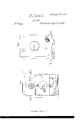
Be it known that I, ROBERT NEWELL, of New, York, N. Y., have invented new and useful Improvements in Manifold PermutationLooks for Doors, Vaults, &c., of which the following is a specification. My invention in4 the manifold permutation lock is represented in u the annexed drawings in connection with parts or prin-v ciples ordinarily attached to other locks, constituting a combination of slides "and tumblers operating .together on the bolt 1n such manner that they can be transposed or set in any given position to which the key may be formed. ,The bit of the key being composed of as manyseparate or movable sections as there are slides in the lock, thereby rendering it in the power of its possessor atany time before projecting the bolt to effect-with lthe aid of an auxiliary key or wrench any necessary permutation in the lock without removing the same or any part of it from the door. y
In order therefore to give a plain and lucid exposition of the drawings accompanying this specification it may bewell to refer to each section as represented thereon and state the application or design of such in their several positions instead of resorting to mere nominal references. In the first place the bolt is furnished with any number of permutation tumblers, or as in the present example with nine, which move one upon the other and between themselves in a perpendicular line on the face or surface ofthe bolt, as shown at z5, t, (Figure A) being there secured and kept in their places by two guides, which are rmly attached to the lock plate oneabove and the other below the bolt designated by g', g', g', g', through which the tumblers operate bythe action of the key. The tumblers are continually forced toward and stop against the stud s, when disconnected from the slides by `means of the springs z, which are separatelyattached to each tumbler. Directly in front and in a horizontal line with the tumblers are a corresponding number of slides, which are attached to and operate in like manner upon the face of the bolt, being kept in their proper places there by two guides g, (7, whichvare firmly secured on the face ofthe bolt near-the top and bottom edge of the same, forming a space between them'and the head of the bolt for the Slides to operate through to rise and fall in con` junction with the tumblers. The slides and tumblersv being of an equal thickness are united together before projecting the bolt by meansof the narrow projections on the ends of theV tumblers which fit accurately and pass into the grooves of the slides as represented on the face of the bolt disconnected from the lock at (Fig. B) t, t, being i.
the tumbler and S, the slide, in this position the slides and tumblersbeoomefas it were one and the same piece alike subjectto the action of the key, both are raised up as one together until they attain `theelevattion given by the key when `the slidesare secured in a stationary position for the action of i.
the bolt. TheV slides are secured in any given position by Vmeans of the `cramp `and nut. VTheV top of the cramp is shown at l, (Fig. A) vaccurately fitted on the two guides, g, g, andalso disconnected from the same at (Fig. E) where it is represented with the screw on the bottom side of the same, which passesthrough the aperture, e, as represented in the slide S, at (Fig. B) `and also through the bolt, which is for the purpose of i receiving the nut, 1v, as exhibited on the back or underside of the bolt, which :lies next the plate of the lock at (Fig. D). The slides .therefore being between the cramp and-the bolt may be secured in any given position i by tightening the nut. The lever, Z, which is also shown on the back of they bolt at (Fig. D) is for the purpose of keeping the bolt from being projected, i when the tion by the cramp. a permuta-tion being al-` ways effected in theV lock when the bolt is back gives rise to thenecessity ofV securingthe Ysame until the necessary arrangement of securing the slides'again to some fixed position is completed, the bolt vconsequently can never be projected while the cramp remains slack. The lever,iZ, aboveV alluded ,to is secured to the vbolt by thescrew, eand acts `9o slides are not secured in somefixedfposithereon, being pressed do-wn by the spring,
s, causing it to catch on the stud, O, `when the nut n, is slacked thereby securing the bolt from moving until Vthe lever is` again raised clear of the stud, which is accomplished by a projection on the side of the. nut, meeting in contact witha likeprojection on the end of the lever, when in the act of tightening the slides in somegiven `position. The stud, O, mentioned here isrmly 'E is shown Vat m, (Fig. E) kand the squarel attached to the plate of the lock passing the shank and the bit. The shank is represented on the drawing at (Fig. D) and the bit disconnected from the same at (Fig. E). The shank` and the bit are connected together Vby means of square perforation through the barrel or pin of the bit, which kon the end of the shank as seen at (Fig. D). They are secured together by means of the tip or nut, which is screwed on the end of the shank, against the barrel or pin of the bit and uniting them together as represented at (Fig. B). The key is designed in this particular for the purpose of inverting the bit on the shank, in order that it may be used von either or bothl sides of the lock, when the sections of the bit are placed in an irregular position as shown at (Fig. A). The key being there represented in one of its forms for use, a, 6,0, d, e, f,`g, 71 t', represent the sections separately disconnected from the bit, exhibiting their various proportions. VThey are attached tothe bit by means of their tenons entering a mortise in the same at f, (Fig. E) and secured therein by virtue of a screw pressing against them l' as represented by the dotted lines in the side of the bit at (Fig. B). The bit may be furnished with any number of sections,
which may be shifted or altered at pleasure Vand be used in any of the different permutations or combinations which that number will admit of. A key with nine sections'like that represented in the drawing is calculated to` give three hundred sixty-two thousand eight hundred and eighty different changes or permutations.
In order to show the action of this lock and the manner of effecting a permutation in the same I will first state that the nut, n,
as seen at (Fig. D) is presented in the lock through an orifice or barrel on the back Vside of the same as seen on Plate No. 2' (Fig. L) for the purpose of receiving the key or wrench which is exhibited on Plate No. 1 at (Fig. C) having two tips on its end, which are adapted to the holes on the top of the nut, by which means the nut is slackened or Vmade tight.
`be slackened, which is alwaysthe case when I will now suppose the nut to the slides are to be set in any given form with the key. Ihe key is therefore inserted in the key hole of the lock and turned as in the act of projecting the bolt until it comes in contact with one side of the mesh in the same causing it to stop in the position as shown at (Fig.V C). The key in its action to said position raises the tumblers,fwhich carrythe slides up with vthem* to theidiifer- Y ent .elevations given by the. sections of the key bit, the slides being nowv arranged after the manner of the key. The wrench is inserted inthe barrels or orifice represented atw on Plate No. 2 (Fig. L) vuntil it becomes connectedwith the-nut n', which must be turned sufficiently to cause the lever Z to frise clear of the stud.0,which is signified Vby the nut stopping-againstthe projection on the end of the lever as'before described.' V'Ihe operation of 'raising the lever also ser 'cures the slides.` Thev nut being screwed firmly againstA the bolt draws. the cramp tight upon the face of the slides thereby compressing them, together in a iiXed permanent position. The bolt may now be projected, whichiwh'en done carries the slides out kwith it, causing'them and the tumblers to become separated in Yconsequence of their projections becoming relieved from the grooves in the f slides. yThe tumblers now drop down below said grooves A,and stop against the stud s." 'The Vprojections lon the ends of the tumblers passing close against the ends of the slidesforms a stayV for the bolt, which cannot `be returned again until the tumblers are raised-up to a sufficient height by the key to bring their projections in a line of intersection with-the grooves in I will now refer to a few sections as repsis' resented on thedrawing, which have not been mentioned as they are common to' other locks. at (Fig. A) is the spring latch. 0, c, gare three studs for receiving the cap, `which confines the various sections to the lock plate. The cap .is seen on Plate No. 3 at R (Fig. N). d is an aperture for receiving the arbor of the pinion, which moves or carries the cross or perpendicular bolts. These bolts are seen connected with the lock at d d (Fig. N) confined in their places by the cap L. Alllthe rest of the sections being` of minor consideration and plainly eX- hibited on the drawings and known to all persons acquainted with the construction of locks renders` it unnecessary to enter further into detail.vr The dierentsections a, b, c, d, e, f, g, 71., z', are secured in the bit of the key by passing their lower ends, orV what may be called their tenons, into a mortise formed in the said bit, for the purpose of Vreceiving them and then pressing them to- .for example claim to be the inventor of permutation tumblers and slides, or of changeable sections in the bit of the key adapting thereto. These having been before used, but constructed and operating in a manner dilferent from that Which I have devised and adopted; but
I do claim- 1. The manner in Which I have constructed the vertically sliding tumblers and connected and` combined them with the slides'and the bolt, in the particular mode herein set forth. 2. I also claim, in combination, the man ner in which a permutation is eiected in them, and the slides secured to any given elevation of the key, by means of the Cramp, the nut and the Wrench, as described. Y
3. I claim likewise the particular manner in Which the different sections are Vsecured Y in the bit ofthe key, by means of their ten- Vons and a tightening screw. i 'Y [FIRSJT PRINTED 1914.]
Publications (1)
| Publication Number | Publication Date |
|---|---|
| US944A true US944A (en) | 1838-09-25 |
Family
ID=2061230
Family Applications (1)
| Application Number | Title | Priority Date | Filing Date |
|---|---|---|---|
| US944D Expired - Lifetime US944A (en) | Photo-litho |
Country Status (1)
| Country | Link |
|---|---|
| US (1) | US944A (en) |
Cited By (2)
| Publication number | Priority date | Publication date | Assignee | Title |
|---|---|---|---|---|
| WO2021204520A1 (en) | 2020-04-10 | 2021-10-14 | Galenus G.H. Ag | Composition comprising resveratrol |
| WO2025076732A1 (en) | 2023-10-11 | 2025-04-17 | The Procter & Gamble Company | A biodegradable flexible package with a personal care composition |
-
0
- US US944D patent/US944A/en not_active Expired - Lifetime
Cited By (4)
| Publication number | Priority date | Publication date | Assignee | Title |
|---|---|---|---|---|
| WO2021204520A1 (en) | 2020-04-10 | 2021-10-14 | Galenus G.H. Ag | Composition comprising resveratrol |
| WO2025076732A1 (en) | 2023-10-11 | 2025-04-17 | The Procter & Gamble Company | A biodegradable flexible package with a personal care composition |
| WO2025077844A1 (en) | 2023-10-11 | 2025-04-17 | The Procter & Gamble Company | A biodegradable flexible package with a personal care composition |
| WO2025077842A1 (en) | 2023-10-11 | 2025-04-17 | The Procter & Gamble Company | Biodegradable flexible package with a liquid food composition |
Similar Documents
| Publication | Publication Date | Title |
|---|---|---|
| US4470277A (en) | Security door locking mechanism | |
| US944A (en) | Photo-litho | |
| US1204410A (en) | Lock. | |
| US1445719A (en) | Keyless padlock | |
| US215A (en) | James mcoloey | |
| US811A (en) | Mortise latch fob | |
| US63230A (en) | Improvement in locks | |
| US413A (en) | Mortise-latch for fastening doors | |
| US685135A (en) | Combination-padlock. | |
| US787A (en) | James mcclory | |
| USRE208E (en) | Kobeet jewell | |
| US844448A (en) | Permutation-lock. | |
| US107590A (en) | Improvement in permutation locks | |
| US1874A (en) | Villiams | |
| US2638A (en) | Door lock and key | |
| DE168434C (en) | Edge latch that cannot be moved when the handle is recessed and only allows the handle to be recessed in the end position. | |
| US1173A (en) | Doob-lock | |
| US606A (en) | Method of fastening bedsteads | |
| US565622A (en) | Cylinder-lock | |
| US1355A (en) | Manweb oe constbttctiktg locks with double catch-bolts | |
| US464579A (en) | Cyrus bussey | |
| US64568A (en) | Improvement in locks | |
| US72408A (en) | Isaac w | |
| US57857A (en) | Improved lock | |
| US100195A (en) | Improved lock |