US9434446B2 - Electric bicycle - Google Patents
Electric bicycle Download PDFInfo
- Publication number
- US9434446B2 US9434446B2 US14/375,367 US201214375367A US9434446B2 US 9434446 B2 US9434446 B2 US 9434446B2 US 201214375367 A US201214375367 A US 201214375367A US 9434446 B2 US9434446 B2 US 9434446B2
- Authority
- US
- United States
- Prior art keywords
- crankshaft
- diameter
- torque sensor
- hanger
- cylinder
- Prior art date
- Legal status (The legal status is an assumption and is not a legal conclusion. Google has not performed a legal analysis and makes no representation as to the accuracy of the status listed.)
- Active
Links
- 238000005304 joining Methods 0.000 claims abstract description 30
- 230000005540 biological transmission Effects 0.000 claims description 56
- 238000001514 detection method Methods 0.000 claims description 31
- 230000001105 regulatory effect Effects 0.000 claims description 30
- 238000004519 manufacturing process Methods 0.000 abstract description 11
- 238000000034 method Methods 0.000 description 13
- 230000008569 process Effects 0.000 description 10
- 230000008859 change Effects 0.000 description 4
- 238000003860 storage Methods 0.000 description 4
- 241000239290 Araneae Species 0.000 description 2
- 230000000386 athletic effect Effects 0.000 description 2
- 230000008878 coupling Effects 0.000 description 2
- 238000010168 coupling process Methods 0.000 description 2
- 238000005859 coupling reaction Methods 0.000 description 2
- 230000035699 permeability Effects 0.000 description 2
- 238000007789 sealing Methods 0.000 description 2
- 239000003990 capacitor Substances 0.000 description 1
- 230000000694 effects Effects 0.000 description 1
- 239000013013 elastic material Substances 0.000 description 1
- 230000004907 flux Effects 0.000 description 1
- 238000009434 installation Methods 0.000 description 1
- 238000005259 measurement Methods 0.000 description 1
- 230000007246 mechanism Effects 0.000 description 1
- 230000004044 response Effects 0.000 description 1
- XLYOFNOQVPJJNP-UHFFFAOYSA-N water Substances O XLYOFNOQVPJJNP-UHFFFAOYSA-N 0.000 description 1
Images


Classifications
-
- B—PERFORMING OPERATIONS; TRANSPORTING
- B62—LAND VEHICLES FOR TRAVELLING OTHERWISE THAN ON RAILS
- B62M—RIDER PROPULSION OF WHEELED VEHICLES OR SLEDGES; POWERED PROPULSION OF SLEDGES OR SINGLE-TRACK CYCLES; TRANSMISSIONS SPECIALLY ADAPTED FOR SUCH VEHICLES
- B62M6/00—Rider propulsion of wheeled vehicles with additional source of power, e.g. combustion engine or electric motor
- B62M6/40—Rider propelled cycles with auxiliary electric motor
- B62M6/45—Control or actuating devices therefor
- B62M6/50—Control or actuating devices therefor characterised by detectors or sensors, or arrangement thereof
-
- B—PERFORMING OPERATIONS; TRANSPORTING
- B62—LAND VEHICLES FOR TRAVELLING OTHERWISE THAN ON RAILS
- B62M—RIDER PROPULSION OF WHEELED VEHICLES OR SLEDGES; POWERED PROPULSION OF SLEDGES OR SINGLE-TRACK CYCLES; TRANSMISSIONS SPECIALLY ADAPTED FOR SUCH VEHICLES
- B62M3/00—Construction of cranks operated by hand or foot
- B62M3/003—Combination of crank axles and bearings housed in the bottom bracket
-
- B—PERFORMING OPERATIONS; TRANSPORTING
- B62—LAND VEHICLES FOR TRAVELLING OTHERWISE THAN ON RAILS
- B62M—RIDER PROPULSION OF WHEELED VEHICLES OR SLEDGES; POWERED PROPULSION OF SLEDGES OR SINGLE-TRACK CYCLES; TRANSMISSIONS SPECIALLY ADAPTED FOR SUCH VEHICLES
- B62M6/00—Rider propulsion of wheeled vehicles with additional source of power, e.g. combustion engine or electric motor
- B62M6/40—Rider propelled cycles with auxiliary electric motor
- B62M6/60—Rider propelled cycles with auxiliary electric motor power-driven at axle parts
-
- F—MECHANICAL ENGINEERING; LIGHTING; HEATING; WEAPONS; BLASTING
- F16—ENGINEERING ELEMENTS AND UNITS; GENERAL MEASURES FOR PRODUCING AND MAINTAINING EFFECTIVE FUNCTIONING OF MACHINES OR INSTALLATIONS; THERMAL INSULATION IN GENERAL
- F16C—SHAFTS; FLEXIBLE SHAFTS; ELEMENTS OR CRANKSHAFT MECHANISMS; ROTARY BODIES OTHER THAN GEARING ELEMENTS; BEARINGS
- F16C3/00—Shafts; Axles; Cranks; Eccentrics
- F16C3/04—Crankshafts, eccentric-shafts; Cranks, eccentrics
- F16C3/06—Crankshafts
- F16C3/10—Crankshafts assembled of several parts, e.g. by welding by crimping
-
- Y—GENERAL TAGGING OF NEW TECHNOLOGICAL DEVELOPMENTS; GENERAL TAGGING OF CROSS-SECTIONAL TECHNOLOGIES SPANNING OVER SEVERAL SECTIONS OF THE IPC; TECHNICAL SUBJECTS COVERED BY FORMER USPC CROSS-REFERENCE ART COLLECTIONS [XRACs] AND DIGESTS
- Y10—TECHNICAL SUBJECTS COVERED BY FORMER USPC
- Y10T—TECHNICAL SUBJECTS COVERED BY FORMER US CLASSIFICATION
- Y10T74/00—Machine element or mechanism
- Y10T74/18—Mechanical movements
- Y10T74/18056—Rotary to or from reciprocating or oscillating
- Y10T74/18232—Crank and lever
Definitions
- the present invention relates to an electric bicycle that can be driven by an auxiliary driving force generated by an electric motor in addition to a human driving force generated by a pedal force from a pedal.
- a known electric bicycle includes a power storage such as a battery and an electric motor powered by the power storage.
- a power storage such as a battery
- an electric motor powered by the power storage.
- Such an electric bicycle can be easily driven even on an uphill road by adding an auxiliary driving force (assist force) of the electric motor to a pedal force (human driving force) from a pedal.
- a force corresponding to a pedal force applied to the pedal is detected by a torque sensor, and then an auxiliary driving force corresponding to the pedal force is generated from the electric motor.
- the torque sensor is disposed near, for example, a crankshaft to detect a force transmitted from the crankshaft to a chain ring (also called a front sprocket or a crank gear), or the torque sensor is disposed in, for example, the hub of a rear wheel to detect a force transmitted to the rear wheel through a chain.
- the torque sensor detects the force through a force transmission path such as the chain. This may change or lose the direction of a force or an amount of a force through the force transmission path such as the chain, preventing a direct measurement of a force to the pedal so as to reduce correspondence with a pedal force.
- the torque sensor does not detect the force through the transmission path such as a chain.
- a pedal force can be measured in a relatively satisfactory manner.
- a motor unit containing the electric motor via a bracket is disposed below, for example, a hanger (also called a bottom bracket) that connects a lower pipe (also called a main pipe), a vertical pipe (also called a seat tube), and a chain stay.
- the torque sensor is disposed at the front of the motor unit.
- the crankshaft is rotationally supported at the front of the motor unit disposed below the hanger, a torque detecting cylinder that transmits the rotation of the crankshaft to the crank gear is disposed around the crankshaft coaxially with the crankshaft, and the torque sensor is attached to the torque detecting cylinder (Patent Literature 1, etc.).
- a crankshaft is rotatably supported at the location of the hanger.
- a structure that supports a crank with the motor unit disposed below the hanger is a frame structure that is different from that of the typical bicycle, disadvantageously leading to uncomfortable feeling and higher manufacturing cost.
- the hanger connected to the lower pipe and so on needs to be disposed in the upper part of the bicycle, leading to the need for locating the lower pipe as well in the upper part of the bicycle. This disadvantageously makes it difficult for a rider to move a foot over the lower pipe when the rider rides on or gets off the electric bicycle.
- a crankshaft is rotatably supported at the location of a hanger as in the typical bicycle, the hanger containing a torque sensor.
- the frame structure of the electric bicycle is similar to that of the typical bicycle, thereby suppressing uncomfortable feeling and an increase in manufacturing cost to a certain level.
- the hanger and the lower pipe are located as in the typical bicycle, allowing a rider to easily move a foot over the lower pipe.
- the joining section between a crank arm and a crankshaft may have a larger diameter than that of the typical bicycle so as to have higher stiffness than the typical bicycle.
- a larger force may be applied to the joining section between a crank arm and a crankshaft than that of the typical bicycle.
- the joining section between the crank arm and the crankshaft is desirably larger in diameter than that of a typical electric bicycle so as to have larger stiffness.
- crankshaft of an electric bicycle is larger in diameter than a conventional crankshaft, a special torque sensor is necessary for the large-diameter crankshaft. This may considerably increase the manufacturing cost.
- using the crankshaft having a large diameter increases the size of the torque sensor and thus the torque sensor needs to be located in a special hanger having quite a large diameter.
- using the special hanger having quite a large diameter may further increase the manufacturing cost or the size increase of the hanger may cause uncomfortable feeling.
- An object of the present invention is to Provide an electric bicycle that can suppress an increase in manufacturing cost and minimizes a size increase of a hanger containing a torque sensor with the joining section having a large diameter between a crankshaft and a crank arm.
- the present invention is an electric bicycle that can be driven by adding an auxiliary driving force generated by an electric motor to a human driving force generated by a pedal force from pedal, the electric bicycle including: a torque sensor that detects a force corresponding to a pedal force with a crankshaft rotatably disposed in a hanger coupled to the lower end of a vertical pipe, wherein the crankshaft is divided into a crankshaft body on the periphery of which the torque sensor is disposed, and an auxiliary crankshaft connected to one side of the crankshaft body, and the diameter of the joining section between the auxiliary crankshaft and a crank arm and the diameter of the joining section between the crankshaft body and the crank arm are larger than the diameter of the connecting section between the crankshaft body and the auxiliary crankshaft.
- the crankshaft body has a large-diameter part and a small-diameter part having a smaller diameter than the large-diameter part
- the small-diameter part has a torque detection cylinder that is fit onto the small-diameter part so as to integrally rotate with the small-diameter part
- the torque sensor having a magnetostriction portion formed on the periphery of the torque detection cylinder
- the auxiliary crankshaft is coupled to the end of the small-diameter part.
- the crankshaft is divided into the crankshaft body on the periphery of which the torque sensor is disposed, and the auxiliary crankshaft connected to one side of the crankshaft body, and the diameter of the joining section between the auxiliary crankshaft and the crank arm and the diameter of the joining section between the crankshaft body and the crank arm are larger than the diameter of the connecting section between the crankshaft body and the auxiliary crankshaft.
- This increases the diameter of the joining section between the auxiliary crankshaft and the crank arm of the crankshaft body, thereby keeping high stiffness.
- crankshaft is divided into the crankshaft body and the auxiliary crankshaft.
- the auxiliary crankshaft subsequently connected to the crankshaft body facilitates the assembly of the crankshaft and the torque sensor in the hanger.
- the crankshaft body is identical in diameter to a conventional crankshaft, allowing the torque sensor to have the same size and shape as a conventional torque sensor.
- the crankshaft, the torque sensor, and the hanger can have small sizes (suppressed size increase). The use of the conventional torque sensor can reduce manufacturing cost.
- the crankshaft body has a point near the joining section between the crankshaft body and the auxiliary crankshaft, the point being rotatably supported by a bearing, a wire guide member is disposed between the bearing and an inner cylinder disposed in the hanger, and the torque sensor is connected to a torque sensor connecting wire that is laterally extended out of the hanger through the wire guide member.
- a portion where the torque sensor connecting wire protrudes from the side of the hanger is covered with a wire cap circular in side view.
- the hanger contains the metallic inner cylinder having bearings provided in both of the left and right ends of the inner cylinder, the bearing rotatably supporting the crankshaft body, and the inner cylinder covers the torque sensor, the torque detection cylinder on the periphery of which the magnetostriction portion of the torque sensor is formed, and a region between the bearings on the crankshaft body.
- the inner cylinder prevents rainwater from entering the location of the torque sensor.
- the metallic inner cylinder can prevent external noise or the like from entering the signal lines of the torque sensor.
- the locations of the crankshaft and the torque sensor can be combined into a unit covered with the inner cylinder and thus the crankshaft and the torque sensor can be relatively easily assembled into the hanger with high efficiency.
- the large-diameter part of the crankshaft body has a rotary force transmission cylinder that is rotatably fit onto the large-diameter part via a large-diameter bearing part, the rotary force transmission cylinder and the torque detection cylinder are connected so as to integrally rotate with each other, and the rotary force transmission cylinder has a human driving force output ring with gear portions in multiple stages, the human driving force output ring being fit onto the rotary force transmission cylinder so as to integrally rotate with the rotary force transmission cylinder.
- the human driving force output ring having the gear portions in multiple stages is disposed at a location corresponding to the large-diameter part of the crankshaft body via the rotary force transmission cylinder and the large-diameter bearing part.
- the rotary force transmission cylinder is rotatably disposed via the bearing on the metallic inner cylinder provided in the hanger, the human driving force output ring having the gear portions in the multiple stages is fit onto the rotary force transmission cylinder, a position regulating ring that regulates the position of the bearing in the axial direction is fit into a groove formed on the inner cylinder, the groove has an inclined surface that increases in diameter toward the location of the bearing, and the position regulating ring with a reduced diameter is disposed in the groove.
- the bearing rotatably supporting the rotary force transmission cylinder and the human driving force output ring having the gear portions in the multiple stages are satisfactorily positioned in the axial direction of the crankshaft by the position regulating ring.
- the gear portions formed on the human driving force output ring are also satisfactorily positioned in the axial direction. This can prevent the occurrence of problems that may cause a faulty changing operation on the gear portions of the chain, thereby satisfactorily changing the gear portions of the chain.
- the crankshaft is divided into the crankshaft body on the periphery of which the torque sensor is disposed, and the auxiliary crankshaft connected to one side of the crankshaft body, and the diameter of the joining section between the auxiliary crankshaft and the crank arm and the diameter of the joining section between the crankshaft body and the crank arm are larger than the diameter of the connecting section between the crankshaft body and the auxiliary crankshaft.
- This increases the diameter of the joining section between the auxiliary crankshaft and the crank arm of the crankshaft body, thereby keeping high stiffness on the joining section. Additionally, the reliability of the electric bicycle can be improved.
- the joining section between the auxiliary crankshaft and the crank arm can be increased in diameter; meanwhile, the crankshaft body is identical in diameter to the conventional crankshaft, allowing the torque sensor to have the same size and shape as the conventional torque sensor.
- the crankshaft, the torque sensor, and the hanger can have small sizes (suppressed size increase). The use of the conventional torque sensor can reduce the manufacturing cost.
- the wire guide member is disposed between the bearing rotatably supporting the crankshaft body and the inner cylinder disposed in the hanger, and the torque sensor is connected to the torque sensor connecting wire that is laterally extended out of the hanger through the wire guide member.
- the torque sensor connecting wire can be satisfactorily extended out of the hanger.
- the portion where the torque sensor connecting wire protrudes from the side of the hanger is covered with the wire cap circular in side view.
- the hanger contains the metallic inner cylinder having the bearings provided in both of the left and right ends of the inner cylinder, the bearing rotatably supporting the crankshaft body, and the inner cylinder covers the torque sensor, the torque detection cylinder on the periphery of which the magnetostriction portion of the torque sensor is formed, and the region between the bearings on the crankshaft body.
- the inner cylinder prevents rainwater from entering the location of the torque sensor, improving the reliability.
- the metallic inner cylinder can prevent external noise or the like from entering the signal lines of the torque sensor, also improving the reliability.
- the locations of the crankshaft and the torque sensor can be combined into the unit covered with the inner cylinder and thus the crankshaft and the torque sensor can be relatively easily assembled with high efficiency.
- the large-diameter part of the crankshaft body has the rotary force transmission cylinder that is rotatably fit onto the large-diameter part via the large-diameter bearing part, the rotary force transmission cylinder and the torque detection cylinder are connected so as to integrally rotate with each other, and the rotary force transmission cylinder has the human driving force output ring with the gear portions in the multiple stages, the human driving force output ring being fit onto the rotary force transmission cylinder so as to integrally rotate with the rotary force transmission cylinder.
- the rotary force transmission cylinder is rotatably disposed via the bearing on the metallic inner cylinder provided in the hanger, the human driving force output ring having the gear portions in the multiple stages is fit onto the rotary force transmission cylinder, the position regulating ring that regulates the position of the bearing in the axial direction is fit into the groove formed on the inner cylinder, the groove has the inclined surface that increases in diameter toward the location of the bearing, and the position regulating ring with a reduced diameter is disposed in the groove.
- the human driving force output ring is fit onto the rotary force transmission cylinder such that the position of the human driving force output ring is satisfactorily regulated in contact with the bearing so as not to move into the hanger. This can prevent the occurrence of problems that may cause a faulty changing operation on the gear portions of the chain, also improving the reliability.
- FIG. 1 is an overall side view of an electric bicycle according to an embodiment of the present invention.
- FIG. 2 is a partially cut side view of the electric bicycle.
- FIG. 3 is an exploded perspective view of a hanger and a crank unit in the electric bicycle.
- FIG. 4 is a longitudinal section of the hanger of the electric bicycle and a portion near the hanger.
- FIG. 5 is a cross-sectional side arrow view of the electric bicycle taken along line V-V of FIG. 4 .
- FIG. 6 is a cross-sectional side arrow view of the electric bicycle taken along line VI-VI of FIG. 4 .
- FIG. 7 is a cross-sectional side arrow view of the electric bicycle taken along line VII-VII of FIG. 4 .
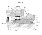
- FIG. 8 is an enlarged cross-sectional view showing the principal part of the electric bicycle.
- FIG. 9 is a cross-sectional view showing an assembly process for assembling the crankshaft, the crank sensor, and so on of the electric bicycle.
- FIG. 10 is a cross-sectional view showing the assembly process of the electric bicycle.
- FIG. 11 is a cross-sectional view showing the assembly process of the electric bicycle.
- FIG. 12 is a cross-sectional view showing the assembly process of the electric bicycle.
- FIG. 13 is a cross-sectional view showing the assembly process of the electric bicycle.
- FIG. 14 is a cross-sectional view showing the assembly process of the electric bicycle.
- FIG. 15 is a cross-sectional view showing the assembly process of the electric bicycle.
- FIG. 16 is a cross-sectional view showing the assembly process of the electric bicycle.
- FIG. 17 is a cross-sectional view showing the assembly process of the electric bicycle.
- FIG. 18 is a cross-sectional view showing the assembly process of the electric bicycle.
- a lateral direction is a direction set with respect to a traveling direction.
- reference numeral 1 denotes an electric bicycle including a metallic frame (also called a body frame) 2 composed of a head tube 2 a , a front fork 2 b , a down tube (also called a down tube 2 c ) 2 c , a vertical pipe (also called a seat tube) 2 d , a chain stay 2 e , a seat stay 2 f , and a hanger (also called a bottom bracket) 2 g , a front wheel 3 rotatably attached to the lower end of the front fork 2 b , a rear wheel 4 rotatably attached to the rear end of the chain stay 2 e , a handle bar 5 that changes the direction of the front wheel 3 , a saddle 6 , a crank 7 composed of a crankshaft 17 and a pair of crank arms 18 , pedals 8 rotatably attached to the ends of the crank arms 18 , an electric motor 10 that generates an auxiliary driving force (assist) (assist).
- the electric motor 10 is disposed in a hub (also called a front hub) 16 of the front wheel 3 while the control unit (not shown) is disposed near the attaching part of the battery 12 .
- the control unit (not shown) may be disposed at another location, for example, the manual operation part.
- the battery 12 is an example of a storage device.
- a secondary battery is preferably used but another example of the storage device may be a capacitor.
- the electric motor 10 may be disposed in the rear hub instead of the front hub 16 .
- the hanger 2 g is provided so as to connect the rear end of the down tube 2 c , the lower end of the vertical pipe 2 d , and a battery-mounting bracket 19 connected to the front end of the chain stay 2 e .
- the crankshaft 17 is rotatably disposed in the hanger 2 g and a torque sensor 23 for detecting a force corresponding to a pedal force is disposed in the hanger 2 g .
- FIG. 3 shows only a part supporting a gear portion 13 a on the chain ring 13 .
- the gear portion 13 a is also called a spider.
- the crankshaft 17 is divided into a crankshaft body 17 A on a periphery of which the torque sensor 23 is provided, and an auxiliary crankshaft 17 B connected to one side (the left side in the present embodiment) of the crankshaft body 17 A.
- the crankshaft body 17 A and the auxiliary crankshaft 17 B are connected to each other with a coupling stud 25 .
- the crankshaft body 17 A includes a large-diameter part 17 Aa that is located on the right side so as to be coupled to the right crank arm 18 ( 18 A) and a small-diameter part 17 Ab that has a smaller diameter than the large-diameter part 17 Aa and is located at the center and on the left side.
- a torque detection cylinder (sensing pipe) 24 on a periphery of which a magnetostriction portion 23 a of the torque sensor 23 is formed is fit onto the small-diameter part 17 Ab of the crankshaft body 17 A so as to integrally rotate with the small-diameter part 17 Ab that is located substantially at the center of the crankshaft 17 in a lateral direction.
- the left end of the small-diameter part 17 Ab of the crankshaft body 17 A is connected to the auxiliary crankshaft 17 B.
- a joining section 17 Ba between the auxiliary crankshaft 17 B and the left crank arm 18 ( 18 B) has a diameter D 1 that is larger than a diameter D 2 of a connecting section (a part of the small-diameter part 17 Ab) 17 Ac between the crankshaft body 17 A and the auxiliary crankshaft 17 B. Furthermore, a joining section 17 Ad between the crankshaft body 17 A and the right crank arm 18 ( 18 A) has a diameter D 3 that is larger than the diameter D 2 of the connecting section (the part of the small-diameter part 17 Ab) 17 Ac between the crankshaft body 17 A and the auxiliary crankshaft 17 B.
- a joining section 17 Ad between the crankshaft body 17 A and the right crank arm 18 ( 18 A) has a diameter D 3 that is larger than the diameter D 2 of the connecting section (the part of the small-diameter part 17 Ab) 17 Ac between the crankshaft body 17 A and the auxiliary crankshaft 17 B.
- reference numeral 34 denotes a locking bolt that locks the crank arm to the crankshaft
- reference numerals 2 gc and 2 gd denote holes that are formed to discharge rainwater or the like entering from the vertical pipe 2 d , to the outside (downward).
- the torque detection cylinder (sensing pipe) 24 is fit onto the crankshaft 17 so as to integrally rotate with the crankshaft 17 such that a toothed part (serration part) 24 a formed on the torque detection cylinder 24 is engaged with a toothed part (serration part) 17 Aba formed on the outer surface of the small-diameter part 17 Ab of the crankshaft body 17 A.
- a rotary force transmission cylinder 27 is rotatably fit onto the large-diameter part 17 Aa of the crankshaft 17 via a large-diameter bearing part 26 .
- the rotary force transmission cylinder 27 has a toothed part (serration part) 27 a on the inner surface of the left end.
- the toothed part (serration part) 27 a of the rotary force transmission cylinder 27 is engaged with a toothed part (serration part) 24 b formed on the outer surface of the right end of the torque detection cylinder 24 . This transmits the rotation of the torque detection cylinder 24 to the rotary force transmission cylinder 27 , integrally rotating the rotary force transmission cylinder 27 with the torque detection cylinder 24 .
- a part of the outer surface of the torque detection cylinder 24 has the magnetostriction portion 23 a that fluctuates in magnetic permeability in response to the application of a pedal force transmitted to the torque detection cylinder 24 through the crankshaft 17 and a search coil 23 b that reads a change of magnetic permeability as a change of magnetic flux with a small clearance from the magnetostriction portion 23 a .
- the magnetostriction portion 23 a and the search coil 23 b constitute the torque sensor 23 that detects a pedal force based on the torsional force of the torque detection cylinder 24 .
- the search coil 23 b and a coil holder 23 c that holds the search coil 23 b are fit onto the torque detection cylinder 24 so as to rotate with respect to the torque detection cylinder 24 .
- the chain ring 13 and the rear sprocket 14 each include a three-speed transmission gear.
- the chain ring 13 has gear portions 13 a that are mounted with large, medium, and small diameters.
- a derailleur 22 (Only FIGS. 1 and 2 show the derailleur 22 on the rear wheel) changes the position of the chain 15 so as to change gears.
- the chain ring 13 is fit onto the rotary force transmission cylinder 27 so as to integrally rotate with the rotary force transmission cylinder 27 .
- toothed parts (serration parts) 13 b and 27 b are respectively formed on the inner surface of the chain ring 13 (the inner surface of the spider) and a point on the right side of the outer surface of the rotary force transmission cylinder 27 .
- the toothed parts (serration parts) 13 b and 27 b are engaged with each other, transmitting the rotation of the rotary force transmission cylinder 27 to the chain ring 13 so as to integrally rotate the chain ring 13 with the rotary force transmission cylinder 27 .
- the hanger 2 g contains a metallic inner cylinder 28 .
- the inner cylinder 28 is rotatably supported via left and right bearings 29 ( 29 A, 29 B).
- the left bearing 29 A is fixed such that the inner surface of the bearing 29 A is mounted near a connecting section between the small-diameter part 17 Ab of the crankshaft body 17 A and the auxiliary crankshaft 17 B while the inner surface of the left end of the inner cylinder 28 having a small diameter is mounted on the outer surface of the left bearing 29 A.
- the right bearing 29 B is fixed such that the inner surface of the bearing 29 B is mounted on the outer surface of the left end of the rotary force transmission cylinder 27 .
- Each of the bearings 29 has a sealing part on the side (a sealing part 29 Bs of the right bearing 29 B is shown in FIG. 8 only and is omitted in FIGS. 5 and 7 ). This prevents water or the like from entering the mounting space of the torque sensor 23 through, for example, the mounting space of the ball portion of the bearing 29 .
- an external thread 28 a continuing to a flange 28 b is formed on the outer surface on the right end of the inner cylinder 28 so as to be screwed into an internal thread 2 ga formed on the inner surface of the right end of the hanger 2 g .
- the left end of the inner cylinder 28 is inserted and attached into the left end of the hanger 2 g via an auxiliary cylinder 30 .
- an external thread 30 b formed continuing to a flange 30 a of the auxiliary cylinder 30 is screwed and attached into the internal thread 2 ga formed on the inner surface of the left end of the hanger 2 g .
- the inner cylinder 28 covers the torque sensor 23 , the torque detection cylinder 24 , and a region on the crankshaft body 17 A between the bearings 29 .
- the left end of the inner cylinder 28 is radially extended from a contact point with the inner surface of the auxiliary cylinder 30 to a contact point with the outer surface of the left bearing 29 A.
- the inner cylinder 28 has a radially extended side part that is partially cut such that a wire guide member 31 is disposed between the left bearing 29 A and an inner surface on the outer periphery of the left end of the inner cylinder 28 .
- the wire guide member 31 is made of an elastic material such as rubber. Torque sensor connecting wires 32 connected to the torque sensor 23 penetrate the wire guide member 31 and pass through the side of the wire guide member 31 to the outside of the hanger 2 g .
- a wire cap 33 circular in side view is provided at a position facing the left side of the inner cylinder 28 . Moreover, the wire cap 33 covers a portion where the torque sensor connecting wires 32 protrude from the side of the hanger 2 g . The outer surface of the wire cap 33 has a partially cut portion. The torque sensor connecting wires 32 are extended out of a cut portion 33 a of the wire cap 33 .
- a terminal holder 38 that holds the torque sensor connecting terminal of the torque sensor connecting wire 32 is connected to the coil holder 23 c of the torque sensor 23 .
- the terminal holder 38 has an annular shape with a protrusion 38 a provided in the circumferential direction (in the present embodiment, the upper part of FIG. 6 ).
- the terminal holder 38 is connected to the coil holder 23 c in a state in which the protrusion 38 a is located in a recess 28 e formed on the upper end of the inner cylinder 28 .
- the search coil 23 b and the coil holder 23 c of the torque sensor 23 are attached with a small clearance between the search coil 23 b and the magnetostriction portion 23 a formed on the outer surface of the torque detection cylinder 24 . If the search coil 23 b and the coil holder 23 c of the torque sensor 23 rotate with the torque detection cylinder 24 , the protrusion 38 a of the terminal holder 38 comes into contact with the inner wall surface of the recess 28 e of the inner cylinder 28 , regulating the positions of the search coil 23 b and the coil holder 23 c of the torque sensor 23 in the circumferential direction.
- the chain ring 13 acting as a human driving force output ring having the gear portions 13 a for gear shifting is fit onto the rotary force transmission cylinder 27 such that the position of the chain ring 13 is regulated so as not to move into the hanger 2 g in the axial direction of the crankshaft 17 .
- the chain ring 13 is attached with an attaching ring 35 fit into the outer surface of the left end of the chain ring 13 such that the position of the chain ring 13 is regulated so as not to move outward in the axial direction of the crankshaft 17 .
- the chain ring 13 is fit onto the rotary force transmission cylinder 27 such that the left end of the toothed part 13 b comes into contact with a protrusion 27 d formed on the rotary force transmission cylinder 27 from the right side and the position of the chain ring 13 is regulated so as not to move into the hanger 2 g in the axial direction of the crankshaft 17 .
- the protrusion 27 d comes into contact with the right side of the right bearing 293 and the right bearing 29 B comes into contact with a position regulating ring 37 that regulates the position of the right bearing 29 B from the left side. This regulates the position of the rotary force transmission cylinder 27 in the axial direction of the crankshaft 17 .
- the right bearing 29 B is attached such that the position of the bearing 29 B is regulated in the axial direction of the crankshaft 17 by a step 28 c formed on the inner surface near the right end of the inner cylinder 28 and a position regulating ring 36 fit into a groove 28 d formed on the inner surface of the right end of the inner cylinder 28 .
- inclined surfaces 28 da and 27 fa are formed on the opposite sides from the side where the bearing 29 B is provided so as to increase in diameter toward the location of the bearing 29 B.
- the position regulating rings 36 and 37 are both metallic and elastic and are disposed with reduced diameters in the grooves 28 d and 27 f .
- the position regulating rings 36 and 37 that regulate the position of the bearing 29 B are fit into the grooves 28 d and 27 f , the position regulating rings 36 and 37 in contact with the inclined surfaces 28 da and 27 fa increase in diameter so as to be precisely positioned in the axial direction.
- the right bearing 29 B is precisely positioned in the axial direction.
- the gear portions 13 a of the chain ring 13 are also satisfactorily positioned in the axial direction.
- the chain 15 switched for the gear portions 13 a does not cause a faulty changing operation.
- crankshaft 17 and the torque sensor 23 are assembled into a unit in the inner cylinder 28 .
- a crank unit 40 ( FIGS. 14 and 15 ) assembled into a unit is installed into the hanger 2 g.
- the crankshaft body 17 A (specifically, the small-diameter part 17 Ab of the crankshaft body 17 A) is inserted in the torque detection cylinder 24 having attached the torque sensor 23 and the like, and then a position regulating ring 41 for regulating the position of the torque detection cylinder 24 is attached to the crankshaft body 17 A.
- the left bearing 29 A and a position regulating ring 42 are attached to the small-diameter part 17 Ab of the crankshaft body 17 A.
- FIGS. 9 and 10 first, the crankshaft body 17 A (specifically, the small-diameter part 17 Ab of the crankshaft body 17 A) is inserted in the torque detection cylinder 24 having attached the torque sensor 23 and the like, and then a position regulating ring 41 for regulating the position of the torque detection cylinder 24 is attached to the crankshaft body 17 A.
- the left bearing 29 A and a position regulating ring 42 are attached to the small-diameter part 17 Ab of the crankshaft body 17 A.
- the rotary force transmission cylinder 27 and the position regulating ring (for regulating the position of the right crank arm 18 ) 42 are fit onto the large-diameter part 17 Aa of the crankshaft body 17 A with the left bearing 29 B, the large-diameter bearing part 26 , and so on being attached to the rotary force transmission cylinder 27 .
- the crankshaft body 17 A is inserted into the inner cylinder 28 with the torque sensor 23 , the torque detection cylinder 24 , the rotary force transmission cylinder 27 , and so on being attached to the crankshaft body 17 A.
- the position regulating ring (for regulating the position of the right bearing 29 B) 36 is then attached to the crankshaft body 17 A.
- the auxiliary crankshaft 173 is attached to the left end of the crankshaft body 17 A (the end of the small-diameter part 17 Ab) with the coupling stud 25 .
- the crank unit 40 covered with the inner cylinder 28 is completed with the torque sensor 23 attached to the crankshaft 17 .
- the torque sensor connecting wires 32 extended out of the left bearing 29 A are covered with the protecting member 42 .
- the crank unit 40 is inserted into the hanger 2 g .
- the auxiliary cylinder 30 is screwed into the hanger 2 g with a tool 43 so as to insert the protecting member 42 between the auxiliary cylinder 30 and the inner cylinder 28 .
- the wire cap 33 is placed onto the side of the left bearing 29 A, and then the torque sensor connecting wires 32 are extended outward in a predetermined direction.
- the chain ring 13 is then attached to the rotary force transmission cylinder 27 with the attaching ring 35 .
- the crank arms 18 are attached to both ends of the crankshaft 17 with the locking bolts 34 .
- the crankshaft 17 and the torque sensor 23 can be satisfactorily attached to the hanger 2 g.
- the crankshaft 17 is divided into the crankshaft body 17 A on the periphery of which the torque sensor 23 is provided, and the auxiliary crankshaft 17 B connected to one side of the crankshaft body 17 A.
- the diameter D 1 of the joining section between the auxiliary crankshaft 17 B and the crank arm 18 B and the diameter D 3 of the joining section 17 Ad between the crankshaft body 17 A and the right crank arm 18 ( 18 A) are larger than the diameter D 2 of the connecting section between the crankshaft body 17 A and the auxiliary crankshaft 17 B.
- the joining sections between the auxiliary crankshaft 17 B, the crankshaft body 17 A, and the crank arms 18 B and 18 A can be increased in diameter, thereby keeping high stiffness.
- the joining section 17 Ad between the crankshaft body 17 A and the right crank arm 18 ( 18 A) is substantially identical in diameter to the large-diameter part 17 Aa of the crankshaft body 17 A. This can keep high stiffness for the joining section.
- crankshaft 17 is divided into the crankshaft body 17 A and the auxiliary crankshaft 17 B, even after the torque sensor 23 is attached to the small-diameter part of the crankshaft body 17 A, the auxiliary crankshaft 17 B is connected to the crankshaft body 17 A so as to easily install the crankshaft 17 and the torque sensor 23 into the hanger 2 g.
- the small-diameter part 17 Ab having the attached torque sensor 23 on the crankshaft body 17 A is identical in diameter to that of a conventional crankshaft.
- the torque sensor 23 may be identical in size or shape to a conventional torque sensor.
- the crankshaft 17 , the torque sensor 23 , and the hanger 2 g can be small in size (suppressed increase in size) and the use of a conventional torque sensor can suppress manufacturing cost.
- a new and large torque sensor is used in the case of a crankshaft having a larger diameter than a conventional crankshaft and a torque sensor sized accordingly. This may require an extremely large hanger and cause uncomfortable feeling.
- a new torque sensor is necessary and thus may considerably increase the manufacturing cost.
- the wire guide member 31 is disposed between the right bearing 29 A that rotatably supports the crankshaft body 17 A and the inner cylinder 28 disposed in the hanger 2 g , and the torque sensor connecting wires 32 are laterally extended out of the hanger 2 g through the wire guide member 31 .
- the torque sensor connecting wires 32 can be satisfactorily extended out of the hanger 2 g .
- the wire cap 33 circular in side view is provided so as to cover a portion where the torque sensor connecting wires 32 protrude from the side of the hanger 2 g .
- the torque sensor connecting wires 32 extended from any position in the circumferential direction of the hanger 2 g can be extended from a predetermined point of the wire cap 33 .
- crank unit 40 where the crankshaft 17 and the torque sensor 23 are attached is screwed into the hanger 2 g .
- This does not fix the position of extending the torque sensor connecting wires 32 in the circumferential direction of the hanger 2 g .
- the torque sensor connecting wires 32 extended from any point can be extended in the predetermined direction from the wire cap 33 because the torque sensor connecting wires 32 are circumferentially provided in the wire cap 33 .
- the torque sensor connecting wires 32 can be satisfactorily covered with the wire cap 33 , improving the appearance.
- the metallic inner cylinder 28 is provided in the hanger 2 g with the bearings 29 ( 29 A, 29 B) disposed in both ends of the inner cylinder 28 so as to rotatably support the crankshaft body 17 A.
- the inner cylinder 28 covers the torque sensor 23 , the torque detection cylinder 24 , and the region between the bearings 29 ( 29 A, 29 B) on the crankshaft body 17 A. Even if rainwater enters the hanger 2 g through the vertical pipe 2 d , the inner cylinder 28 prevents rainwater from entering the location of the torque sensor 23 , improving reliability.
- the metallic inner cylinder 28 can prevent external noise from entering the signal lines (torque sensor connecting wires 32 ) of the torque sensor 23 , also improving reliability.
- the locations of the crankshaft 17 and the torque sensor 23 can be combined into a unit covered with the inner cylinder 28 . Thus, the crankshaft 17 and the torque sensor 23 can be relatively easily installed into the hanger 2 g with high efficiency.
- the rotary force transmission cylinder 27 is rotatably fit onto the large-diameter part 17 Aa of the crankshaft body 17 A via the large-diameter bearing part 26 , the rotary force transmission cylinder 27 and the torque detection cylinder 24 are connected so as to integrally rotate with each other, and the chain ring 13 having the gear portions 13 a in multiple stages is fit onto the rotary force transmission cylinder 27 so as to integrally rotate with each other.
- the rotary force transmission cylinder 27 is rotatably disposed via the right bearing 29 B on the inner cylinder 28 provided in the hanger 2 g , the chain ring 13 having the gear portions 13 a in the multiple stages is fit onto the rotary force transmission cylinder 27 , the position regulating ring 36 that regulates the position of the right bearing 29 B in the axial direction is fit into the groove 28 d formed on the inner cylinder 28 , the inclined surface 28 da is formed in the groove 28 d so as to increase in diameter toward the location of the bearing, and the position regulating ring 36 with a reduced diameter is disposed in the groove 28 d .
- the chain ring 13 is fit onto the rotary force transmission cylinder 27 such that the position of the chain ring 13 is satisfactorily regulated in contact with the bearing 29 B so as not to move into the hanger 2 g .
- This can prevent the occurrence of problems that may cause a faulty changing operation on the gear portions 13 a of the chain 15 , thereby improving the reliability of the bicycle 1 .
- the transmission path of a human driving force between the crankshaft 17 and the chain ring 13 does not include a mechanism that does not transmit a rotary force, e.g., a one-way clutch.
- the present invention is preferably applied if a coaster brake operated by rotating pedals in an opposite direction is disposed on the hub of a rear wheel.
- the present invention is not limited to the coaster brake and is also applicable to an ordinary brake, e.g., a drum brake operated by a brake lever provided on a handle bar.
- the chain 15 is a driving force transmitting member that transmits a pedal force from the pedal 8 to the rear wheel 4 .
- the present invention is not limited to the driving force transmitting member and thus the chain 15 may be replaced with a toothed belt.
- the chain ring 13 may be replaced with a driving front gear as a human driving force output ring for outputting a human driving force while the rear sprocket 14 may be replaced with a rear gear as a rear ring provided on the hub of the rear wheel.
- the present invention is applicable to various electric bicycles that can be driven by adding an auxiliary driving force generated by an electric motor to a human driving force generated by a pedal force from a pedal.
Abstract
Description
- Patent Literature 1: Japanese Patent Laid-Open No. 2003-118673
- Patent Literature 2: Japanese Patent Laid-Open No. 8-297059
- Patent Literature 3: Japanese Patent Laid-Open No. 2007-230410
Claims (6)
Applications Claiming Priority (1)
| Application Number | Priority Date | Filing Date | Title |
|---|---|---|---|
| PCT/JP2012/001578 WO2013132535A1 (en) | 2012-03-08 | 2012-03-08 | Electric bicycle |
Publications (2)
| Publication Number | Publication Date |
|---|---|
| US20150020621A1 US20150020621A1 (en) | 2015-01-22 |
| US9434446B2 true US9434446B2 (en) | 2016-09-06 |
Family
ID=47528483
Family Applications (1)
| Application Number | Title | Priority Date | Filing Date |
|---|---|---|---|
| US14/375,367 Active US9434446B2 (en) | 2012-03-08 | 2012-03-08 | Electric bicycle |
Country Status (5)
| Country | Link |
|---|---|
| US (1) | US9434446B2 (en) |
| EP (1) | EP2824025B1 (en) |
| JP (1) | JP5100920B1 (en) |
| CN (1) | CN104144848B (en) |
| WO (1) | WO2013132535A1 (en) |
Cited By (2)
| Publication number | Priority date | Publication date | Assignee | Title |
|---|---|---|---|---|
| US20160209281A1 (en) * | 2015-01-19 | 2016-07-21 | Rotor Componentes Tecnologicos S.L. | Pedaling Torque and Power Measuring Device for a Bicycle |
| US20160272278A1 (en) * | 2015-03-20 | 2016-09-22 | Yamaha Hatsudoki Kabushiki Kaisha | Sensor assembly and drive unit for bicycle and bicycle |
Families Citing this family (20)
| Publication number | Priority date | Publication date | Assignee | Title |
|---|---|---|---|---|
| JP5872972B2 (en) * | 2012-06-21 | 2016-03-01 | ブリヂストンサイクル株式会社 | Sensor unit assembly structure and bicycle |
| WO2014103212A1 (en) * | 2012-12-28 | 2014-07-03 | パナソニック株式会社 | Electric bicycle |
| US10235682B2 (en) * | 2013-03-11 | 2019-03-19 | Capital One Services, Llc | Systems and methods for providing social discovery relationships |
| JP5968267B2 (en) * | 2013-06-07 | 2016-08-10 | ブリヂストンサイクル株式会社 | Crankshaft assembly and electric assist bicycle equipped with the same |
| JP2014240248A (en) * | 2013-06-12 | 2014-12-25 | ブリヂストンサイクル株式会社 | Power-assisted bicycle |
| DE102014202484B3 (en) | 2014-02-12 | 2015-05-21 | Schaeffler Technologies AG & Co. KG | Wave for a bicycle camp |
| DE102014202483B3 (en) * | 2014-02-12 | 2015-05-21 | Schaeffler Technologies AG & Co. KG | Wave for a bicycle camp |
| SK50192015A3 (en) * | 2015-05-20 | 2016-12-01 | Frantiĺ Ek Paldan | Bike driven by oscillating cranks movements |
| US10526041B2 (en) * | 2017-06-13 | 2020-01-07 | Shimano Inc. | Bicycle crank assembly |
| CN107336793A (en) * | 2017-07-04 | 2017-11-10 | 河北工业大学 | Moped axis torque sensor |
| KR102173506B1 (en) | 2017-12-01 | 2020-11-05 | 고고로 아이엔씨. | Security mechanisms for electric motors and associated systems |
| EP3492276B1 (en) * | 2017-12-01 | 2020-01-22 | Gogoro Inc. | Hub apparatus and associated systems |
| CN109506815B (en) * | 2018-12-26 | 2020-12-01 | 重庆理工大学 | Suspension type electric bicycle torque sensor |
| US11780521B2 (en) | 2019-09-27 | 2023-10-10 | The Hive Global, Inc. | Telescopic bicycle seatpost with adjustable uncompressed resting height |
| JP6961655B2 (en) * | 2019-10-11 | 2021-11-05 | ヤマハ発動機株式会社 | Drive unit and electric auxiliary bicycle |
| JP7285452B2 (en) | 2019-12-20 | 2023-06-02 | パナソニックIpマネジメント株式会社 | Electric assist bicycle control method, electric assist bicycle control device, and electric assist bicycle |
| US11932351B2 (en) | 2020-07-17 | 2024-03-19 | The Hive Global, Inc. | Conical bicycle cassette sprocket structure |
| CN113184105A (en) * | 2021-05-20 | 2021-07-30 | 广东高标电子科技有限公司 | Middle-mounted motor transmission mechanism, electric moped driving system and electric moped |
| US20230012006A1 (en) * | 2021-07-12 | 2023-01-12 | The Hive Global, Inc. | Seal for bicycle crank with differential chainring motion |
| DE102022206890A1 (en) * | 2022-07-06 | 2024-01-11 | Robert Bosch Gesellschaft mit beschränkter Haftung | Crank drive of a vehicle that can be operated with muscle power and/or engine power |
Citations (17)
| Publication number | Priority date | Publication date | Assignee | Title |
|---|---|---|---|---|
| US3759592A (en) * | 1972-03-24 | 1973-09-18 | Bearings Seals & Gears Inc | Memory disc drive spindle |
| CN1118434A (en) | 1994-05-18 | 1996-03-13 | 本田技研工业株式会社 | Pedaling force detector FR motor-assisted bicycle |
| JPH08297059A (en) | 1995-04-27 | 1996-11-12 | Bridgestone Cycle Co | Torque detector for bicycle |
| US5749429A (en) * | 1995-04-03 | 1998-05-12 | Suzuki Kabushiki Kaisha | Power assist apparatus of power assisted bicycle |
| US6116114A (en) | 1993-08-23 | 2000-09-12 | Edwards; Craig H. | Rotatable spindle assembly utilizing two-piece spindle |
| JP2000335475A (en) | 1999-05-31 | 2000-12-05 | Matsushita Electric Ind Co Ltd | Driving unit for bicycle with auxiliary power and bicycle with auxiliary power |
| JP2003118673A (en) | 2001-10-16 | 2003-04-23 | Matsushita Electric Ind Co Ltd | Power-assisted bicycle |
| JP2006347547A (en) | 2006-10-02 | 2006-12-28 | Matsushita Electric Ind Co Ltd | Vehicle with auxiliary power device |
| JP2007230410A (en) | 2006-03-02 | 2007-09-13 | Matsushita Electric Ind Co Ltd | Power-assisted bicycle |
| CN101279630A (en) | 2007-04-02 | 2008-10-08 | 坎培诺洛有限公司 | Instrument-equipped bicycle component and detection unit for equipping such a component |
| DE102007062156A1 (en) | 2007-12-21 | 2009-06-25 | Schaeffler Kg | Bottom bracket with torque sensors |
| DE202010017365U1 (en) | 2010-11-05 | 2011-10-19 | Schaeffler Technologies Gmbh & Co. Kg | Bottom bracket unit with speed sensor |
| US20120166105A1 (en) * | 2009-02-06 | 2012-06-28 | Momes Gmbh | Apparatus For Measuring And Determining The Force, The Torque And The Power On A Crank, In Particular The Pedal Crank Of A Bicycle |
| WO2012136143A1 (en) * | 2011-04-08 | 2012-10-11 | 深圳市琛玛华夏科技有限公司 | Electric-assisted bike torque sensor |
| WO2013042319A1 (en) * | 2011-09-21 | 2013-03-28 | パナソニック株式会社 | Human-powered drive force detection apparatus for electric bicycle |
| US8485050B2 (en) * | 2011-10-07 | 2013-07-16 | Li-Ho Yao | Torque sensor assembly for a power-assisted bicycle |
| WO2014184826A1 (en) * | 2013-05-16 | 2014-11-20 | パナソニックIpマネジメント株式会社 | Electrically assisted bicycle |
-
2012
- 2012-03-08 EP EP12870422.8A patent/EP2824025B1/en active Active
- 2012-03-08 JP JP2012532399A patent/JP5100920B1/en not_active Expired - Fee Related
- 2012-03-08 CN CN201280071107.4A patent/CN104144848B/en active Active
- 2012-03-08 US US14/375,367 patent/US9434446B2/en active Active
- 2012-03-08 WO PCT/JP2012/001578 patent/WO2013132535A1/en active Application Filing
Patent Citations (22)
| Publication number | Priority date | Publication date | Assignee | Title |
|---|---|---|---|---|
| US3759592A (en) * | 1972-03-24 | 1973-09-18 | Bearings Seals & Gears Inc | Memory disc drive spindle |
| US6116114A (en) | 1993-08-23 | 2000-09-12 | Edwards; Craig H. | Rotatable spindle assembly utilizing two-piece spindle |
| CN1118434A (en) | 1994-05-18 | 1996-03-13 | 本田技研工业株式会社 | Pedaling force detector FR motor-assisted bicycle |
| US5749429A (en) * | 1995-04-03 | 1998-05-12 | Suzuki Kabushiki Kaisha | Power assist apparatus of power assisted bicycle |
| JPH08297059A (en) | 1995-04-27 | 1996-11-12 | Bridgestone Cycle Co | Torque detector for bicycle |
| JP2000335475A (en) | 1999-05-31 | 2000-12-05 | Matsushita Electric Ind Co Ltd | Driving unit for bicycle with auxiliary power and bicycle with auxiliary power |
| JP2003118673A (en) | 2001-10-16 | 2003-04-23 | Matsushita Electric Ind Co Ltd | Power-assisted bicycle |
| JP2007230410A (en) | 2006-03-02 | 2007-09-13 | Matsushita Electric Ind Co Ltd | Power-assisted bicycle |
| JP2006347547A (en) | 2006-10-02 | 2006-12-28 | Matsushita Electric Ind Co Ltd | Vehicle with auxiliary power device |
| JP2009006991A (en) | 2007-04-02 | 2009-01-15 | Campagnolo Spa | Instrument-equipped bicycle component and detection unit for equipping such component |
| CN101279630A (en) | 2007-04-02 | 2008-10-08 | 坎培诺洛有限公司 | Instrument-equipped bicycle component and detection unit for equipping such a component |
| US7861599B2 (en) | 2007-04-02 | 2011-01-04 | Campagnolo, S.R.L. | Instrument-equipped bicycle component and detection unit for equipping such a component |
| DE102007062156A1 (en) | 2007-12-21 | 2009-06-25 | Schaeffler Kg | Bottom bracket with torque sensors |
| US20110006760A1 (en) * | 2007-12-21 | 2011-01-13 | Schaeffler Technologies Gmbh & Co. Kg | Bottom bracket with a torque sensor |
| US8797027B2 (en) | 2007-12-21 | 2014-08-05 | Schaeffler Technologies AG & Co. KG | Bottom bracket with a torque sensor unit |
| US20120166105A1 (en) * | 2009-02-06 | 2012-06-28 | Momes Gmbh | Apparatus For Measuring And Determining The Force, The Torque And The Power On A Crank, In Particular The Pedal Crank Of A Bicycle |
| DE202010017365U1 (en) | 2010-11-05 | 2011-10-19 | Schaeffler Technologies Gmbh & Co. Kg | Bottom bracket unit with speed sensor |
| WO2012136143A1 (en) * | 2011-04-08 | 2012-10-11 | 深圳市琛玛华夏科技有限公司 | Electric-assisted bike torque sensor |
| WO2013042319A1 (en) * | 2011-09-21 | 2013-03-28 | パナソニック株式会社 | Human-powered drive force detection apparatus for electric bicycle |
| US8485050B2 (en) * | 2011-10-07 | 2013-07-16 | Li-Ho Yao | Torque sensor assembly for a power-assisted bicycle |
| WO2014184826A1 (en) * | 2013-05-16 | 2014-11-20 | パナソニックIpマネジメント株式会社 | Electrically assisted bicycle |
| JPWO2014184826A1 (en) * | 2013-05-16 | 2017-02-23 | パナソニックIpマネジメント株式会社 | Electric assist bicycle |
Non-Patent Citations (2)
| Title |
|---|
| Extended European Search Report, Mar. 13, 2015; European Patent Application No. 12870422.8 (8 pages). |
| Office Action issued in corresponding Chinese Patent Application No. 201280071107.4 on Dec. 14, 2015 (6 pages). |
Cited By (4)
| Publication number | Priority date | Publication date | Assignee | Title |
|---|---|---|---|---|
| US20160209281A1 (en) * | 2015-01-19 | 2016-07-21 | Rotor Componentes Tecnologicos S.L. | Pedaling Torque and Power Measuring Device for a Bicycle |
| US9810593B2 (en) * | 2015-01-19 | 2017-11-07 | Rotor Componentes Tecnologicos S.L. | Pedaling torque and power measuring device for a bicycle |
| US20160272278A1 (en) * | 2015-03-20 | 2016-09-22 | Yamaha Hatsudoki Kabushiki Kaisha | Sensor assembly and drive unit for bicycle and bicycle |
| US9701363B2 (en) * | 2015-03-20 | 2017-07-11 | Yamaha Hatsudoki Kabushiki Kaisha | Sensor assembly and drive unit for bicycle and bicycle |
Also Published As
| Publication number | Publication date |
|---|---|
| EP2824025A1 (en) | 2015-01-14 |
| JP5100920B1 (en) | 2012-12-19 |
| EP2824025A4 (en) | 2015-04-15 |
| CN104144848A (en) | 2014-11-12 |
| WO2013132535A1 (en) | 2013-09-12 |
| US20150020621A1 (en) | 2015-01-22 |
| EP2824025B1 (en) | 2017-05-03 |
| JPWO2013132535A1 (en) | 2015-07-30 |
| CN104144848B (en) | 2017-03-29 |
Similar Documents
| Publication | Publication Date | Title |
|---|---|---|
| US9434446B2 (en) | Electric bicycle | |
| EP2939916B1 (en) | Electric bicycle | |
| US9718514B2 (en) | Electrically assisted bicycle | |
| US7516677B2 (en) | Torsion detecting sleeve member and torque-detecting device | |
| US9381972B2 (en) | Power-assisted bicycle | |
| US7207584B2 (en) | Motorized bicycle drive system using a standard freewheel and left-crank drive | |
| TWI473744B (en) | Bicycle motor control unit and bicycle | |
| EP2783972B1 (en) | Driving unit and electric assist bicycle | |
| US20130049444A1 (en) | Bicycle rear hub | |
| EP2743169B1 (en) | Driving unit and electric assist bicycle | |
| EP2930096A1 (en) | Electric hub and electric bicycle | |
| EP2743168B1 (en) | Driving unit and electric assist bicycle | |
| JP7054817B2 (en) | Case mounting structure and electric bicycle | |
| US11643159B2 (en) | Electric power generator for human-powered vehicle | |
| US20220411003A1 (en) | Electrical assembly for human-powered vehicle | |
| US20230061862A1 (en) | Hub assembly for human-powered vehicle | |
| CN106904243B (en) | Electric bicycle transmission device and electric bicycle with same | |
| US20220315155A1 (en) | Bicycle part and method of forming bicycle part | |
| CN116766825A (en) | Electrical component for a human powered vehicle | |
| US20230043341A1 (en) | Motor unit and electric bicycle | |
| JP2022042879A (en) | Wheel speed sensor and jig for wheel speed sensor | |
| CN114670972A (en) | Hub assembly for a human powered vehicle | |
| CN114684315A (en) | Hub for manpower vehicle | |
| CN116512814A (en) | Hub for a human powered vehicle | |
| JP2016088277A (en) | Drive unit and electric assist bicycle |
Legal Events
| Date | Code | Title | Description |
|---|---|---|---|
| AS | Assignment |
Owner name: PANASONIC CORPORATION, JAPAN Free format text: ASSIGNMENT OF ASSIGNORS INTEREST;ASSIGNOR:KAWAKAMI, MASAFUMI;REEL/FRAME:033877/0247 Effective date: 20140625 |
|
| AS | Assignment |
Owner name: PANASONIC INTELLECTUAL PROPERTY MANAGEMENT CO., LTD., JAPAN Free format text: ASSIGNMENT OF ASSIGNORS INTEREST;ASSIGNOR:PANASONIC CORPORATION;REEL/FRAME:034194/0143 Effective date: 20141110 Owner name: PANASONIC INTELLECTUAL PROPERTY MANAGEMENT CO., LT Free format text: ASSIGNMENT OF ASSIGNORS INTEREST;ASSIGNOR:PANASONIC CORPORATION;REEL/FRAME:034194/0143 Effective date: 20141110 |
|
| STCF | Information on status: patent grant |
Free format text: PATENTED CASE |
|
| MAFP | Maintenance fee payment |
Free format text: PAYMENT OF MAINTENANCE FEE, 4TH YEAR, LARGE ENTITY (ORIGINAL EVENT CODE: M1551); ENTITY STATUS OF PATENT OWNER: LARGE ENTITY Year of fee payment: 4 |
|
| AS | Assignment |
Owner name: PANASONIC INTELLECTUAL PROPERTY MANAGEMENT CO., LTD., JAPAN Free format text: CORRECTIVE ASSIGNMENT TO CORRECT THE ERRONEOUSLY FILED APPLICATION NUMBERS 13/384239, 13/498734, 14/116681 AND 14/301144 PREVIOUSLY RECORDED ON REEL 034194 FRAME 0143. ASSIGNOR(S) HEREBY CONFIRMS THE ASSIGNMENT;ASSIGNOR:PANASONIC CORPORATION;REEL/FRAME:056788/0362 Effective date: 20141110 |
|
| MAFP | Maintenance fee payment |
Free format text: PAYMENT OF MAINTENANCE FEE, 8TH YEAR, LARGE ENTITY (ORIGINAL EVENT CODE: M1552); ENTITY STATUS OF PATENT OWNER: LARGE ENTITY Year of fee payment: 8 |