JP7285452B2 - Electric assist bicycle control method, electric assist bicycle control device, and electric assist bicycle - Google Patents

Electric assist bicycle control method, electric assist bicycle control device, and electric assist bicycle Download PDF

Info

Publication number
JP7285452B2
JP7285452B2 JP2019229825A JP2019229825A JP7285452B2 JP 7285452 B2 JP7285452 B2 JP 7285452B2 JP 2019229825 A JP2019229825 A JP 2019229825A JP 2019229825 A JP2019229825 A JP 2019229825A JP 7285452 B2 JP7285452 B2 JP 7285452B2
Authority
JP
Japan
Prior art keywords
assisted bicycle
power
state
determination
walking
Prior art date
Legal status (The legal status is an assumption and is not a legal conclusion. Google has not performed a legal analysis and makes no representation as to the accuracy of the status listed.)
Active
Application number
JP2019229825A
Other languages
Japanese (ja)
Other versions
JP2021098389A (en
Inventor
仁 吉澤
Current Assignee (The listed assignees may be inaccurate. Google has not performed a legal analysis and makes no representation or warranty as to the accuracy of the list.)
Panasonic Intellectual Property Management Co Ltd
Original Assignee
Panasonic Intellectual Property Management Co Ltd
Priority date (The priority date is an assumption and is not a legal conclusion. Google has not performed a legal analysis and makes no representation as to the accuracy of the date listed.)
Filing date
Publication date
Application filed by Panasonic Intellectual Property Management Co Ltd filed Critical Panasonic Intellectual Property Management Co Ltd
Priority to JP2019229825A priority Critical patent/JP7285452B2/en
Publication of JP2021098389A publication Critical patent/JP2021098389A/en
Application granted granted Critical
Publication of JP7285452B2 publication Critical patent/JP7285452B2/en
Active legal-status Critical Current
Anticipated expiration legal-status Critical

Links

Images

Classifications

    • YGENERAL TAGGING OF NEW TECHNOLOGICAL DEVELOPMENTS; GENERAL TAGGING OF CROSS-SECTIONAL TECHNOLOGIES SPANNING OVER SEVERAL SECTIONS OF THE IPC; TECHNICAL SUBJECTS COVERED BY FORMER USPC CROSS-REFERENCE ART COLLECTIONS [XRACs] AND DIGESTS
    • Y02TECHNOLOGIES OR APPLICATIONS FOR MITIGATION OR ADAPTATION AGAINST CLIMATE CHANGE
    • Y02TCLIMATE CHANGE MITIGATION TECHNOLOGIES RELATED TO TRANSPORTATION
    • Y02T10/00Road transport of goods or passengers
    • Y02T10/60Other road transportation technologies with climate change mitigation effect
    • Y02T10/72Electric energy management in electromobility

Description

本発明は、電動アシスト自転車の制御方法、電動アシスト自転車の制御装置、および、電動アシスト自転車に関する。 TECHNICAL FIELD The present invention relates to a method for controlling a power-assisted bicycle, a control device for a power-assisted bicycle, and a power-assisted bicycle.

近年、電動アシスト自転車が押し歩きの状態のときに、アシストを行う電動アシスト自転車の利用が拡大している。特許文献1には、手動のスイッチを通じて、ユーザからの所定の入力があったときに、電動アシスト自転車の状態が押し歩きであると判定して、アシストを行う電動アシスト自転車等が開示されている。 In recent years, there has been an increase in the use of electrically assisted bicycles that provide assistance when the electrically assisted bicycle is in a state of pushing and walking. Patent Literature 1 discloses a power-assisted bicycle or the like that determines that the state of the power-assisted bicycle is pushing and walking when there is a predetermined input from the user through a manual switch, and provides assistance. .

特許第5634273号公報Japanese Patent No. 5634273

しかしながら、特許文献1に開示される電動アシスト自転車は、電動アシスト自転車が押し歩きの状態であるかに関するユーザからの回答の入力なしに、電動アシスト自転車が押し歩きの状態であるか否かを判定することはできない。 However, the power-assisted bicycle disclosed in Patent Document 1 determines whether or not the power-assisted bicycle is in a state of pushing and walking without inputting an answer from the user regarding whether the power-assisted bicycle is in a state of pushing and walking. you can't.

本発明は、電動アシスト自転車が押し歩きの状態であるか否かを、ユーザからの回答の入力を必要とせずに、自身で判断できる電動アシスト自転車の制御方法、電動アシスト自転車の制御装置、および、電動アシスト自転車を提供する。 The present invention provides a control method for a power-assisted bicycle, a control device for a power-assisted bicycle, and a control device for a power-assisted bicycle that can determine by itself whether or not the power-assisted bicycle is in a state of pushing and walking without requiring input of an answer from the user. , offering electric assist bicycles.

本発明の一態様に係る電動アシスト自転車の制御方法は、前記電動アシスト自転車におけるペダル踏力またはクランク回転数と、車体速度とを検出する第1検出ステップと、前記ペダル踏力または前記クランク回転数と、前記車体速度とを用いて、前記電動アシスト自転車が、停止、押し歩き、惰性走行および通常走行のうちの少なくとも1つの状態であるかを判定する第1判定ステップと、前記第1判定ステップが行われてから所定時間経過した後に、前記第1判定ステップでの判定結果に基づいて、前記電動アシスト自転車が前記押し歩き、および、前記惰性走行のうちのいずれの状態であるかを判定する第2判定ステップと、前記電動アシスト自転車が前記押し歩きの状態であると前記第2判定ステップで判定した場合に、前記電動アシスト自転車が備えるモータを駆動して、前記押し歩きを支援するための電動アシストを行う電動アシストステップと、を含む。 A control method for a power-assisted bicycle according to an aspect of the present invention includes a first detection step of detecting a pedaling force or crank rotation speed and a vehicle body speed in the power-assisted bicycle, the pedal effort or the crank rotation speed, a first determination step of determining whether the power-assisted bicycle is in at least one state of stopping, pushing, coasting, and normal running using the vehicle body speed; and the first determination step. After a predetermined period of time has passed since the first determination step, a second determination is made as to whether the power-assisted bicycle is in the state of the push-walking state or the coasting state based on the determination result of the first determination step. a determination step; and, when it is determined in the second determination step that the power-assisted bicycle is in the state of pushing and walking, driving a motor provided in the power-assisted bicycle to assist the pushing-walking. and an electrically assisted step for performing

本発明の一態様に係る電動アシスト自転車の制御装置は、前記電動アシスト自転車におけるペダル踏力またはクランク回転数と、車体速度とを取得する取得部と、前記取得部が取得した前記ペダル踏力または前記クランク回転数と、前記車体速度とを用いて、前記電動アシスト自転車が、停止、押し歩き、惰性走行および通常走行のうちのいずれの状態であるかを判定する第1判定部と、前記第1判定部での判定結果に基づいて、前記電動アシスト自転車が前記押し歩き、および、前記惰性走行のうちのいずれの状態であるかを判定する第2判定部と、前記第2判定部で、前記電動アシスト自転車が前記押し歩きの状態であると判定した場合に、前記電動アシスト自転車が備えるモータを駆動して、前記押し歩きを支援するための電動アシストを行う電動アシスト部と、を備える。 A control device for a power-assisted bicycle according to an aspect of the present invention includes an acquisition unit that acquires a pedaling force or crank rotation speed and a vehicle body speed of the power-assisted bicycle; a first determination unit that determines whether the electrically power-assisted bicycle is in a stopped state, a push-walking state, an inertia running state, or a normal running state using the number of revolutions and the vehicle body speed; a second determination unit that determines whether the power-assisted bicycle is in one of the pushing-walking state and the inertia running state based on the determination result of the second determination unit; an electric assist unit that, when it is determined that the assisted bicycle is in the pushing-walking state, drives a motor included in the electric assisted bicycle to perform electric assist for assisting the pushing-walking.

本発明の一態様に係る電動アシスト自転車は、前記電動アシスト自転車におけるペダル踏力またはクランク回転数と、車体速度とを検出する第1検出部と、前記ペダル踏力または前記クランク回転数と、前記車体速度とを用いて、前記電動アシスト自転車が、停止、押し歩き、惰性走行および通常走行のうちのいずれの状態であるかを判定する第1判定部と、前記第1判定部での判定結果に基づいて、前記電動アシスト自転車が前記押し歩き、および、前記惰性走行のうちのいずれの状態であるかを判定する第2判定部と、前記第2判定部で、前記電動アシスト自転車が前記押し歩きの状態であると判定した場合に、前記電動アシスト自転車が備えるモータを駆動して、前記押し歩きを支援するための電動アシストを行う電動アシスト部と、を備える。 A power-assisted bicycle according to an aspect of the present invention comprises: a first detection unit that detects a pedaling force or crank rotation speed and a vehicle body speed in the power-assisted bicycle; and a first determination unit that determines whether the power-assisted bicycle is in a state of stopping, pushing, coasting, or normal running, and based on the determination result of the first determination unit a second determination unit that determines whether the power-assisted bicycle is in the state of pushing and walking or the inertia running; an electric assist unit that drives a motor included in the electric assist bicycle to perform electric assist for assisting the pushing-walking when it is determined that the state is the state.

本発明の一態様に係る電動アシスト自転車の制御方法等は、電動アシスト自転車が押し歩きの状態であるか否かを、ユーザからの回答の入力を必要とせずに、自身で判断することができる。 A method for controlling a power-assisted bicycle according to an aspect of the present invention can determine by itself whether or not the power-assisted bicycle is in a state of pushing, without requiring input of an answer from the user. .

図1は、実施の形態における電動アシスト自転車の側面図である。FIG. 1 is a side view of a power-assisted bicycle according to an embodiment. 図2は、実施の形態における電動アシスト自転車のハンドルおよび操作部の斜視図である。FIG. 2 is a perspective view of a handlebar and an operating portion of the power-assisted bicycle according to the embodiment. 図3は、実施の形態における電動アシスト自転車のモータ駆動ユニットの構造を示す断面図である。FIG. 3 is a cross-sectional view showing the structure of the motor drive unit of the power-assisted bicycle according to the embodiment. 図4は、実施の形態における電動アシスト自転車の構成を示すブロック図である。FIG. 4 is a block diagram showing the configuration of the power-assisted bicycle according to the embodiment. 図5は、電動アシスト自転車の操作部の平面図である。FIG. 5 is a plan view of the operating portion of the power-assisted bicycle. 図6は、実施の形態における電動アシスト自転車の制御方法を実行する制御装置を搭載する機器の例を示す図である。FIG. 6 is a diagram showing an example of a device equipped with a control device that executes the control method for the power-assisted bicycle according to the embodiment. 図7は、実施の形態における挙動推定部への入力値と判定結果の例を示す図である。7A and 7B are diagrams illustrating examples of input values to a behavior estimation unit and determination results in the embodiment. 図8は、実施の形態における挙動推定部が行う判定処理を示すフローチャートである。FIG. 8 is a flowchart illustrating determination processing performed by a behavior estimation unit according to the embodiment. 図9は、実施の形態における挙動推定部が行う判定に用いられる判定値の例を示す図である。FIG. 9 is a diagram illustrating an example of determination values used for determination performed by the behavior estimation unit in the embodiment. 図10は、実施の形態における押し歩き制御部への入力と出力との例を示す図である。10A and 10B are diagrams illustrating examples of inputs and outputs to a push-walking control unit according to the embodiment. FIG. 図11は、実施の形態における押し歩き制御部への入力と出力との別の例を示す図である。FIG. 11 is a diagram showing another example of inputs and outputs to the push-walking control unit in the embodiment. 図12は、実施の形態における電動アシスト自転車の制御方法によって判定された結果を可視化した例を示す図である。FIG. 12 is a diagram showing an example of visualizing the results determined by the control method for the power-assisted bicycle according to the embodiment. 図13は、実施の形態における電動アシスト自転車の制御方法の処理を示すフローチャートである。FIG. 13 is a flow chart showing the processing of the control method for the power-assisted bicycle according to the embodiment.

以下、実施の形態について、図面を参照しながら具体的に説明する。なお、以下で説明する実施の形態は、いずれも包括的、または、具体的な例を示すものである。以下の実施の形態で示される数値、形状、材料、構成要素、構成要素の配置位置および接続形態、ステップ、ステップの順序などは、一例であり、本発明を限定する主旨ではない。また、以下の実施の形態における構成要素のうち、独立請求項に記載されていない構成要素については、任意の構成要素として説明される。 Hereinafter, embodiments will be specifically described with reference to the drawings. It should be noted that the embodiments described below are all comprehensive or show specific examples. Numerical values, shapes, materials, components, arrangement positions and connection forms of components, steps, order of steps, and the like shown in the following embodiments are examples and are not intended to limit the present invention. Further, among the constituent elements in the following embodiments, constituent elements not described in independent claims will be described as optional constituent elements.

なお、各図は模式図であり、必ずしも厳密に図示されたものではない。また、各図において、実質的に同一の構成に対しては同一の符号を付し、重複する説明は省略、または、簡略化される場合がある。 Each figure is a schematic diagram and is not necessarily strictly illustrated. Moreover, in each figure, the same code|symbol is attached|subjected with respect to substantially the same structure, and the overlapping description may be abbreviate|omitted or simplified.

[電動アシスト自転車の構成]
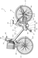
まず、実施の形態に係る電動アシスト自転車の構成について、図1を用いて説明する。図1は、本実施の形態に係る電動アシスト自転車1を示す側面図である。
[Configuration of electric assist bicycle]
First, the configuration of a power-assisted bicycle according to an embodiment will be described with reference to FIG. FIG. 1 is a side view showing a power-assisted bicycle 1 according to this embodiment.

本実施の形態に係る電動アシスト自転車1は、第1モードと、第2モードとを有する。第1モードは、例えばアシストモードであり、ペダル17への踏力に基づく車体10の前進が補助される。車体10の前進が補助されることを、アシストされるともいう。第2モードには、例えば押し歩きモードまたは自走モードが含まれる。押し歩きモードでは、電動アシスト自転車1を押して歩くときの車体10を前へ押す力に基づく車体10の前進が補助される。自走モードでは、電動アシスト自転車1を支えながら進むときの車体10の前進が補助される。各モードの詳細については、後で説明する。 The power-assisted bicycle 1 according to this embodiment has a first mode and a second mode. The first mode is, for example, an assist mode, in which forward movement of the vehicle body 10 is assisted based on the force applied to the pedal 17 . Assisting the forward movement of the vehicle body 10 is also referred to as being assisted. The second mode includes, for example, a push-walking mode or a free-running mode. In the push-walking mode, the forward movement of the vehicle body 10 is assisted based on the force pushing the vehicle body 10 forward when the electrically assisted bicycle 1 is pushed while walking. In the self-propelled mode, the forward movement of the vehicle body 10 is assisted while the electrically assisted bicycle 1 is being supported. Details of each mode will be described later.

図1に示されるように、電動アシスト自転車1は、車体10と、車体10に取り付けられたモータ駆動ユニット20、操作部40、バッテリー50および前照灯60とを備える。車体10は、フレーム11と、前輪12と、後輪13と、ハンドル14と、サドル15と、クランク16と、ペダル17と、駆動スプロケット18と、チェーン19とを備える。モータ駆動ユニット20は、電動モータ21と、電動モータ21を制御する制御装置22とを備える。また、図1には示していないが、電動アシスト自転車1は、クランク回転センサ31と、モータ回転センサ32と、踏力センサ33とを備える(図3および図4を参照)。 As shown in FIG. 1 , the electrically assisted bicycle 1 includes a vehicle body 10 , a motor drive unit 20 attached to the vehicle body 10 , an operating section 40 , a battery 50 and a headlight 60 . The vehicle body 10 includes a frame 11 , front wheels 12 , rear wheels 13 , handlebars 14 , saddle 15 , cranks 16 , pedals 17 , drive sprockets 18 and chains 19 . The motor drive unit 20 includes an electric motor 21 and a control device 22 that controls the electric motor 21 . Although not shown in FIG. 1, the power-assisted bicycle 1 includes a crank rotation sensor 31, a motor rotation sensor 32, and a pedaling force sensor 33 (see FIGS. 3 and 4).

フレーム11は、図1に示されるように、ヘッドパイプ111と、メインフレーム112と、立パイプ113と、フォーク114と、チェーンステー115とを備える。ヘッドパイプ111は、前輪12を支持するフォーク114およびハンドル14を、ヘッドパイプ111の軸を中心に回転自在に支持する。ハンドル14を左右に回すことで、フォーク114に支持された前輪12の向きを左右に回転させることができる。 The frame 11 includes a head pipe 111, a main frame 112, a standing pipe 113, a fork 114, and a chain stay 115, as shown in FIG. The head pipe 111 supports a fork 114 supporting the front wheel 12 and the handle 14 so as to be rotatable around the axis of the head pipe 111 . By turning the handle 14 left and right, the direction of the front wheel 12 supported by the fork 114 can be turned left and right.

メインフレーム112は、ヘッドパイプ111と立パイプ113とを連結する部分である。メインフレーム112の下端部には、クランク16およびモータ駆動ユニット20が取り付けられている。本実施の形態に係る電動アシスト自転車1は、クランク16とモータ駆動ユニット20とが一体化された、いわゆるセンターユニット方式の電動アシスト自転車である。 The main frame 112 is a portion that connects the head pipe 111 and the standing pipe 113 . A crank 16 and a motor drive unit 20 are attached to the lower end of the main frame 112 . The power-assisted bicycle 1 according to the present embodiment is a so-called center unit type power-assisted bicycle in which the crank 16 and the motor drive unit 20 are integrated.

立パイプ113は、サドル15を着脱可能に支持する。具体的には、立パイプ113には、サドル15を支持するシートポストが挿入されて固定される。本実施の形態では、立パイプ113に、バッテリー50が着脱可能に取り付けられている。 The standing pipe 113 detachably supports the saddle 15 . Specifically, a seat post that supports the saddle 15 is inserted into and fixed to the standing pipe 113 . In this embodiment, the battery 50 is detachably attached to the standing pipe 113 .

フォーク114は、前輪12を回転自在に支持する。前輪12を支持するフォーク114には、前照灯60が取り付けられている。チェーンステー115は、後輪13を回転自在に支持する。 The fork 114 rotatably supports the front wheel 12 . A headlamp 60 is attached to the fork 114 that supports the front wheel 12 . Chain stay 115 rotatably supports rear wheel 13 .

ハンドル14には、図2に示されるように、一対のグリップ141およびブレーキレバー142が左右に設けられている。図2は、本実施の形態に係る電動アシスト自転車1のハンドル14および操作部40の斜視図である。 As shown in FIG. 2, the handle 14 is provided with a pair of grips 141 and brake levers 142 on the left and right. FIG. 2 is a perspective view of the handle 14 and the operating portion 40 of the electrically power-assisted bicycle 1 according to this embodiment.

一対のグリップ141は、適切な姿勢で乗車された場合に、手で握られる部分である。また、一対のグリップ141は、電動アシスト自転車1を押し歩く際にも手で握られて、前方への押力を受ける。一対のグリップ141の少なくとも一方には、ユーザ2がグリップ141を握る力またはユーザ2がグリップ141を押す押力を検知する圧力センサ45が設けられていてもよい。 A pair of grips 141 are portions that are held by hands when the vehicle is ridden in an appropriate posture. Also, the pair of grips 141 are gripped by hands when pushing the electrically assisted bicycle 1 and receive forward pushing force. At least one of the pair of grips 141 may be provided with a pressure sensor 45 that detects the force with which the user 2 grips the grip 141 or the pressing force with which the user 2 presses the grip 141 .

一対のブレーキレバー142は、前輪12および後輪13の各々に取り付けられたブレーキ装置(図示せず)の動作レバーである。一方のブレーキレバー142を操作することで、前輪12に取り付けられたブレーキ装置(図示せず)が駆動され、前輪12に対して機械的な制動力を与える。他方のブレーキレバー142を操作することで、後輪13に取り付けられたブレーキ装置(図示せず)が駆動され、後輪13に対して機械的な制動力を与える。 A pair of brake levers 142 are operating levers for braking devices (not shown) attached to each of the front wheels 12 and rear wheels 13 . By operating one brake lever 142 , a brake device (not shown) attached to the front wheels 12 is driven to apply mechanical braking force to the front wheels 12 . By operating the other brake lever 142 , a brake device (not shown) attached to the rear wheel 13 is driven to apply mechanical braking force to the rear wheel 13 .

サドル15は、適切な姿勢で乗車された場合に、人が座る部分である。サドル15には、荷重センサが設けられていてもよい。 The saddle 15 is the part on which a person sits when riding in the proper posture. The saddle 15 may be provided with a load sensor.

クランク16は、図1に示されるように、クランク軸161と、一対のクランクアーム162とを有する。クランクアーム162は、メインフレーム112の両側に1つずつ設けられており、左右方向に延びるクランク軸161の両端に固定されている。クランクアーム162の一方端がクランク軸161に固定され、他方端には、ペダル17が回転自在に固定されている。ペダル17に踏力が加えられた場合、クランクアーム162がクランク軸161を中心に回転し、当該回転による人力駆動力が駆動スプロケット18およびチェーン19を介して後輪13に伝達される。アシストモードで動作する場合には、踏力に基づく人力駆動力と、当該人力駆動力に付加された電動モータ21による補助駆動力とが後輪13に伝達される。 The crank 16 has a crankshaft 161 and a pair of crank arms 162, as shown in FIG. One crank arm 162 is provided on each side of the main frame 112 and fixed to both ends of a crank shaft 161 extending in the left-right direction. One end of the crank arm 162 is fixed to the crankshaft 161, and the pedal 17 is rotatably fixed to the other end. When a pedaling force is applied to the pedal 17 , the crank arm 162 rotates about the crankshaft 161 , and the human power driving force generated by this rotation is transmitted to the rear wheel 13 via the drive sprocket 18 and chain 19 . When operating in the assist mode, the human-powered driving force based on the pedaling force and the auxiliary driving force by the electric motor 21 added to the human-powered driving force are transmitted to the rear wheels 13 .

[モータ駆動ユニットの構造]
次に、モータ駆動ユニットの構造について説明する。図3は、本実施の形態に係る電動アシスト自転車1のモータ駆動ユニット20の構造を示す断面図である。本実施の形態に係るモータ駆動ユニット20は、電動モータ21の出力軸と、人力による出力軸とが同じ一軸式のセンターユニット構造を有する。
[Structure of motor drive unit]
Next, the structure of the motor drive unit will be explained. FIG. 3 is a cross-sectional view showing the structure of the motor drive unit 20 of the electrically assisted bicycle 1 according to this embodiment. Motor drive unit 20 according to the present embodiment has a uniaxial center unit structure in which the output shaft of electric motor 21 and the output shaft by human power are the same.

モータ駆動ユニット20は、図3に示されるように、電動モータ21および制御装置22などが、樹脂製または金属製の筐体28に収納されてユニット化されている。クランク軸161は、筐体28を貫通するように設けられている。なお、クランク軸161は、軸受によって回転可能に支持されている。 As shown in FIG. 3, the motor drive unit 20 includes an electric motor 21, a control device 22, and the like, which are housed in a housing 28 made of resin or metal. The crankshaft 161 is provided so as to pass through the housing 28 . The crankshaft 161 is rotatably supported by bearings.

モータ駆動ユニット20は、さらに、クランク軸161の外周に設けられた、筒状の人力伝達体23、中間筒体24および連動体25と、電動モータ21と連動体25との間に配置された減速機構26と、一方向クラッチ27とを備える。 The motor drive unit 20 is further arranged between the cylindrical human power transmission body 23, the intermediate cylinder body 24 and the interlocking body 25 provided on the outer circumference of the crankshaft 161, and the electric motor 21 and the interlocking body 25. A speed reduction mechanism 26 and a one-way clutch 27 are provided.

人力伝達体23は、クランク軸161に設けられたセレーション部163に嵌め込まれており、クランク軸161と一体的に回転するように設けられている。中間筒体24は、クランク軸161に対しては回転自在に設けられ、かつ、人力伝達体23および連動体25の各々と一体的に回転するように設けられている。連動体25には、駆動スプロケット18が連動体25と一体的に回転するように設けられている。なお、人力伝達体23、中間筒体24および連動体25の各々には、1つ以上のセレーション部が設けられており、互いに嵌まり合うことにより一体的に回転する。なお、セレーション部はスプライン部とも呼ばれる。また、中間筒体24と連動体25との間には、一方向クラッチ27が配置されている。一方向クラッチ27は、中間筒体24上に配置され、ラチェットが連動体25に噛み合うことにより、中間筒体24から連動体25への一方向に回転力を伝達する。 The human power transmission body 23 is fitted in a serration portion 163 provided on the crankshaft 161 and is provided so as to rotate integrally with the crankshaft 161 . Intermediate cylindrical body 24 is rotatably provided with respect to crankshaft 161 and is provided so as to rotate integrally with each of human power transmission body 23 and interlocking body 25 . The interlocking body 25 is provided with a driving sprocket 18 so as to rotate integrally with the interlocking body 25 . One or more serrations are provided in each of the human power transmission body 23, the intermediate cylindrical body 24, and the interlocking body 25, and are integrally rotated by being fitted to each other. Note that the serration portion is also called a spline portion. A one-way clutch 27 is arranged between the intermediate cylinder 24 and the interlocking body 25 . The one-way clutch 27 is arranged on the intermediate cylinder 24 , and the ratchet is engaged with the interlocking body 25 to transmit rotational force in one direction from the intermediate cylinder 24 to the interlocking body 25 .

この構成により、ペダル17への踏力によってクランク軸161が回転し、この回転による人力駆動力が人力伝達体23、中間筒体24、一方向クラッチ27および連動体25を介して駆動スプロケット18に伝えられる。人力駆動力によって駆動スプロケット18が回転することで、駆動スプロケット18に取り付けられたチェーン19が回転し、後輪13が回転する。 With this configuration, the crankshaft 161 rotates due to the force applied to the pedal 17, and the human power driving force generated by this rotation is transmitted to the drive sprocket 18 via the human power transmission body 23, the intermediate cylindrical body 24, the one-way clutch 27 and the interlocking body 25. be done. A chain 19 attached to the drive sprocket 18 is rotated by the rotation of the drive sprocket 18 by the human power driving force, and the rear wheel 13 is rotated.

また、連動体25には、減速機構26を介して、電動モータ21による補助駆動力が伝達される。つまり、電動モータ21による補助駆動力によって連動体25の回転を補助することができるので、連動体25の回転に合わせて駆動スプロケット18および後輪13を回転させることができる。 Further, an auxiliary driving force from the electric motor 21 is transmitted to the interlocking member 25 via the reduction mechanism 26 . That is, the auxiliary driving force of the electric motor 21 can assist the rotation of the interlocking body 25 , so that the drive sprocket 18 and the rear wheel 13 can be rotated in accordance with the rotation of the interlocking body 25 .

電動モータ21は、制御装置22による制御に基づいて、バッテリー50からの電力を受けて駆動する。電動モータ21は、図3に示されるように、回転軸211と、ロータ部212と、歯部213と、ステータ部214とを有する。電動モータ21は、軸受によって回転軸211およびロータ部212が回転可能に支持されている。バッテリー50からの電力を受けてロータ部212が回転し、ロータ部212の回転に合わせて回転軸211および歯部213が回転する。歯部213は、回転軸211の先端側に設けられており、減速機構26の大径歯車部262に嵌まり合う。歯部213が回転することで、大径歯車部262が回転する。 The electric motor 21 is driven by receiving power from the battery 50 under the control of the control device 22 . The electric motor 21 has a rotating shaft 211, a rotor portion 212, a tooth portion 213, and a stator portion 214, as shown in FIG. The electric motor 21 has a rotating shaft 211 and a rotor portion 212 rotatably supported by bearings. The rotor portion 212 rotates by receiving electric power from the battery 50 , and the rotating shaft 211 and the tooth portion 213 rotate along with the rotation of the rotor portion 212 . The toothed portion 213 is provided on the distal end side of the rotary shaft 211 and fits into the large diameter gear portion 262 of the speed reduction mechanism 26 . The rotation of the tooth portion 213 causes the large-diameter gear portion 262 to rotate.

減速機構26は、電動モータ21の回転トルク(すなわち、補助駆動力)が増幅されて連動体25に伝達されるように構成されている。具体的には、図3に示されるように、減速機構26は、回転軸261と、大径歯車部262と、小径歯車部263とを有する。減速機構26の回転軸261および小径歯車部263は、大径歯車部262と一体的に回転する。小径歯車部263は、連動体25の歯車部252に嵌まり合う。小径歯車部263が回転することで、連動体25の歯車部252が回転する。 The speed reduction mechanism 26 is configured to amplify the rotational torque (that is, the auxiliary driving force) of the electric motor 21 and transmit it to the interlocking body 25 . Specifically, as shown in FIG. 3 , the speed reduction mechanism 26 has a rotating shaft 261 , a large diameter gear portion 262 and a small diameter gear portion 263 . The rotating shaft 261 and the small diameter gear portion 263 of the speed reduction mechanism 26 rotate integrally with the large diameter gear portion 262 . The small diameter gear portion 263 fits into the gear portion 252 of the interlocking body 25 . As the small-diameter gear portion 263 rotates, the gear portion 252 of the interlocking body 25 rotates.

このように、本実施の形態では、電動モータ21が生成する補助駆動力は、減速機構26を介して連動体25に伝達される。すなわち、電動モータ21が回転することで、連動体25も回転し、駆動スプロケット18が回転する。これにより、後輪13を回転させることができる。 As described above, in the present embodiment, the auxiliary driving force generated by the electric motor 21 is transmitted to the interlocking body 25 via the speed reduction mechanism 26 . That is, when the electric motor 21 rotates, the interlocking body 25 also rotates, and the drive sprocket 18 rotates. Thereby, the rear wheel 13 can be rotated.

さらに、図3に示されるように、筐体28の内部には、クランク回転センサ31と、モータ回転センサ32と、踏力センサ33とが設けられている。クランク回転センサ31および踏力センサ33は、クランク軸161の近傍に配置されている。モータ回転センサ32は、電動モータ21の回転軸211の近傍に配置されている。 Further, as shown in FIG. 3 , a crank rotation sensor 31 , a motor rotation sensor 32 and a pedaling force sensor 33 are provided inside the housing 28 . Crank rotation sensor 31 and pedaling force sensor 33 are arranged near crankshaft 161 . The motor rotation sensor 32 is arranged near the rotary shaft 211 of the electric motor 21 .

クランク回転センサ31は、歯車状の回転体311と、光検出器312とを有する。回転体311は、中間筒体24と一体的に回転するように設けられている。光検出器312は、互いに対向するように配置された光出射部と受光部とを有する。光検出器312は、回転体311の歯が、光出射部から受光部に至る光の経路を遮る位置に設けられている。回転体311の回転に合わせて歯が光を遮るので、受光部で受光される光が遮られた回数(または、光が受光できた回数)と回転体311の歯の数とに応じて、回転体311の回転数が検出される。回転体311と中間筒体24およびクランク16とが一体的に回転するので、回転体311の回転数は、クランク16の回転数に一致する。このようにして、クランク回転センサ31は、クランク16の回転数を検出することができる。なお、クランク回転センサ31は、クランク16の回転数を検出することができればいかなる構成でもよい。 The crank rotation sensor 31 has a gear-shaped rotor 311 and a photodetector 312 . The rotating body 311 is provided so as to rotate integrally with the intermediate cylinder 24 . The photodetector 312 has a light emitting portion and a light receiving portion arranged to face each other. The photodetector 312 is provided at a position where the teeth of the rotor 311 block the path of light from the light emitting portion to the light receiving portion. Since the teeth block the light as the rotating body 311 rotates, depending on the number of times the light received by the light receiving section is blocked (or the number of times the light can be received) and the number of teeth of the rotating body 311, The rotation speed of the rotating body 311 is detected. Since the rotating body 311 , the intermediate cylindrical body 24 and the crank 16 rotate integrally, the rotation speed of the rotating body 311 matches the rotation speed of the crank 16 . Thus, the crank rotation sensor 31 can detect the rotation speed of the crank 16 . Note that the crank rotation sensor 31 may have any configuration as long as it can detect the rotation speed of the crank 16 .

モータ回転センサ32は、電動モータ21の回転軸211と一体的に回転する磁石321と、ホールIC322とを有する。ホールIC322は、磁石321の回転に応じて変化する磁界の変化を検出することで、磁石321の回転数、すなわち、電動モータ21の回転数を検出する。なお、モータ回転センサ32は、電動モータ21の回転数を検出することができればいかなる構成でもよい。 The motor rotation sensor 32 has a magnet 321 that rotates integrally with the rotating shaft 211 of the electric motor 21 and a Hall IC 322 . The Hall IC 322 detects the number of rotations of the magnet 321 , that is, the number of rotations of the electric motor 21 by detecting a change in the magnetic field that changes according to the rotation of the magnet 321 . Note that the motor rotation sensor 32 may have any configuration as long as it can detect the rotation speed of the electric motor 21 .

踏力センサ33は、磁歪式のトルクセンサであり、人力伝達体23の外周表面に隙間を介して配置されたコイル331と、コイル331と人力伝達体23との間に設けられた磁歪発生部332とを有する。踏力センサ33は、ペダル17への踏力に基づいてクランク軸161が回転することにより発生する人力駆動力を検出する。 The pedal force sensor 33 is a magnetostrictive torque sensor, and includes a coil 331 arranged on the outer peripheral surface of the human power transmission body 23 with a gap therebetween, and a magnetostriction generating part 332 provided between the coil 331 and the human power transmission body 23. and The pedaling force sensor 33 detects the human power driving force generated by the rotation of the crankshaft 161 based on the pedaling force applied to the pedal 17 .

例えば、ペダル17に踏力が加えられて人力駆動力が発生した場合に、磁歪発生部332に歪みが発生し、磁歪発生部332には、透磁率が増加する部位と減少する部位とが発生する。このため、コイル331のインダクタンス差を検出することで、人力駆動力を検出することが可能である。なお、踏力センサ33の構成は特に限定されず、ペダル17への踏力(または人力駆動力)が検出できればいかなる構成でもよい。 For example, when a pedaling force is applied to the pedal 17 to generate a human-powered driving force, distortion occurs in the magnetostriction generating portion 332, and the magnetostriction generating portion 332 has a portion where the magnetic permeability increases and a portion where the magnetic permeability decreases. . Therefore, by detecting the inductance difference of the coils 331, it is possible to detect the human power driving force. The configuration of the pedaling force sensor 33 is not particularly limited, and any configuration may be used as long as the pedaling force (or the human driving force) to the pedal 17 can be detected.

制御装置22は、クランク回転センサ31および踏力センサ33などのセンサによる検出結果に基づいて、電動モータ21の動作を制御する。本実施の形態では、制御装置22は、モータ駆動ユニット20の筐体28の内部に収納されているが、これに限らない。制御装置22は、モータ駆動ユニット20とは別体で設けられていてもよい。 The control device 22 controls the operation of the electric motor 21 based on detection results from sensors such as the crank rotation sensor 31 and the pedaling force sensor 33 . In the present embodiment, the control device 22 is housed inside the housing 28 of the motor drive unit 20, but the present invention is not limited to this. The control device 22 may be provided separately from the motor drive unit 20 .

[電動アシスト自転車の機能構成]
次に、電動アシスト自転車1の機能構成について説明する。図4は、実施の形態における電動アシスト自転車の構成を示すブロック図である。具体的には、図4は、電動アシスト自転車1の構成のうち、電力を使用する主な構成を示している。
[Functional Configuration of Electric Assist Bicycle]
Next, the functional configuration of the electrically assisted bicycle 1 will be described. FIG. 4 is a block diagram showing the configuration of the power-assisted bicycle according to the embodiment. Specifically, FIG. 4 shows a main configuration of the power-assisted bicycle 1 that uses electric power.

図4に示されるように、電動アシスト自転車1の制御装置22は、挙動推定部221と、押し歩き制御部222と、取得部223とを有する。また、制御装置22は、制御部220を備えていてもよい。また、制御部220は、制御装置22の外に備えられていてもよい。制御装置22は、例えば、マイコン(マイクロコントローラ)などで実現され、プログラムが格納された不揮発性メモリ、プログラムを実行するための一時的な記憶領域である揮発性メモリ、入出力ポート、プログラムを実行するプロセッサなどで構成されている。あるいは、制御装置22は、専用の電子回路で実現されてもよい。 As shown in FIG. 4 , the control device 22 of the power-assisted bicycle 1 has a behavior estimation section 221 , a push-walking control section 222 and an acquisition section 223 . Also, the control device 22 may include a control section 220 . Also, the control unit 220 may be provided outside the control device 22 . The control device 22 is implemented by, for example, a microcomputer (microcontroller), and includes a nonvolatile memory storing a program, a volatile memory that is a temporary storage area for executing the program, an input/output port, and a program executing unit. It consists of a processor that Alternatively, controller 22 may be implemented with dedicated electronic circuitry.

制御装置22には、図4に示されるように、電源スイッチ41、手動スイッチ42、ライトスイッチ43、クランク回転センサ31、モータ回転センサ32、踏力センサ33、が接続されている。電源スイッチ41、手動スイッチ42、ライトスイッチ43、クランク回転センサ31、モータ回転センサ32、および、踏力センサ33は、第1検出部の具体例である。また、制御装置22には、圧力センサ45が接続されていてもよい。なお、第1検出部は、上述の各種センサのうち一部を備えている構成であってもよい。制御装置22には、各スイッチに対する操作信号(具体的には、押下の有無)、および、各センサによる検出結果が入力される。 A power switch 41, a manual switch 42, a light switch 43, a crank rotation sensor 31, a motor rotation sensor 32, and a pedaling force sensor 33 are connected to the control device 22, as shown in FIG. The power switch 41, the manual switch 42, the light switch 43, the crank rotation sensor 31, the motor rotation sensor 32, and the pedaling force sensor 33 are specific examples of the first detector. A pressure sensor 45 may also be connected to the control device 22 . In addition, the structure which is provided with some of the above-mentioned various sensors may be sufficient as a 1st detection part. The control device 22 receives an operation signal for each switch (specifically, whether or not the switch is pressed) and a detection result by each sensor.

圧力センサ45は、半導体ピエゾ抵抗拡散圧力センサでもよいし、静電容量圧力センサでもよい。 Pressure sensor 45 may be a semiconductor piezoresistive diffusion pressure sensor or a capacitive pressure sensor.

ここで、半導体ピエゾ抵抗拡散圧力センサは、ダイヤフラムの表面に半導体ひずみゲージを形成しており、外部からの力によってダイヤフラムが変形することによって発生するピエゾ抵抗効果による電気抵抗の変化を電気信号に変換するものである。 Here, the semiconductor piezoresistive diffusion pressure sensor forms a semiconductor strain gauge on the surface of the diaphragm, and converts the change in electrical resistance due to the piezoresistive effect that occurs when the diaphragm is deformed by an external force into an electrical signal. It is something to do.

また、静電容量形圧力センサは、ガラスの固定極とシリコンの可動極を対向させ、コンデンサを形成し、外部からの力によって可動極が変形して発生する静電容量の変化を電気信号に変換するものである。 In the capacitive pressure sensor, a fixed electrode made of glass and a movable electrode made of silicon face each other to form a capacitor. It converts.

圧力センサ45は、グリップ141に設置され、ユーザ2がグリップ141を押す際の力を検出する。 The pressure sensor 45 is installed on the grip 141 and detects the force when the user 2 presses the grip 141 .

また、制御装置22には、バッテリー50と、電動モータ21、表示部44および前照灯60とが接続されている。制御装置22は、バッテリー50から供給される電力を、電動モータ21、表示部44および前照灯60に供給する。 Also, the battery 50 , the electric motor 21 , the display unit 44 and the headlight 60 are connected to the control device 22 . The control device 22 supplies electric power supplied from the battery 50 to the electric motor 21 , the display section 44 and the headlamp 60 .

電動モータ21は、軸を持ち回転する回転子(ロータ)と、回転子と相互作用して回転モーメントを発生させる固定子(ステータ)、回転子の回転を外部に伝える回転軸、回転軸を支える軸受、損失により発生した熱を冷却する冷却装置などから構成される。電動モータ21は、固定子と回転子のいずれかが回転変化する際に発生する磁界の変化によって、駆動力を得る。 The electric motor 21 supports a rotor that has a shaft and rotates, a stator that interacts with the rotor to generate a rotational moment, a rotating shaft that transmits the rotation of the rotor to the outside, and a rotating shaft. It consists of a bearing and a cooling device that cools the heat generated by loss. The electric motor 21 obtains driving force from changes in the magnetic field generated when either the stator or the rotor rotates.

バッテリー50は、電動モータ21の駆動用の電力を貯める蓄電池である。バッテリー50は、例えば、二次電池であるが、キャパシタなどであってもよい。前照灯60は、リムダイナモ、ハブダイナモまたは電池によって電力を得て、点灯するライトである。 The battery 50 is a storage battery that stores electric power for driving the electric motor 21 . The battery 50 is, for example, a secondary battery, but may be a capacitor or the like. The headlamp 60 is a light that is powered by a rim dynamo, a hub dynamo, or a battery.

挙動推定部221は、電動アシスト自転車1の走行状態を判定する。例えば、挙動推定部221は、電動アシスト自転車1が、停止、押し歩き、惰性走行および通常走行のうちの少なくとも1つの状態であるか否かを判定してもよい。ここで、電動アシスト自転車1が押し歩きの状態であるとは、ユーザ2が電動アシスト自転車1に跨らずに、電動アシスト自転車1のハンドル14を握った状態で、電動アシスト自転車1の横に立って歩く状態を指す。 The behavior estimator 221 determines the running state of the electrically power-assisted bicycle 1 . For example, the behavior estimator 221 may determine whether the power-assisted bicycle 1 is in at least one state of stopping, pushing, coasting, and normal running. Here, when the power-assisted bicycle 1 is in a state of pushing and walking, the user 2 is standing next to the power-assisted bicycle 1 while grasping the handle 14 of the power-assisted bicycle 1 without straddling the power-assisted bicycle 1 . Refers to standing and walking.

挙動推定部221は、上記の判定を行うために、ペダル踏力またはクランク回転数と、車体速度とに関する情報を用いてもよい。ペダル踏力は、踏力センサ33から、クランク回転数は、クランク回転センサ31から、車体速度は、車速センサが取得したデータから算出される。車速センサは、走行スピードを感知するホイールセンサから成る。 The behavior estimator 221 may use information on the pedal effort or the number of crank revolutions and the vehicle body speed in order to make the above determination. The pedaling force is calculated from the pedaling force sensor 33, the crank rotation speed is calculated from the crank rotation sensor 31, and the vehicle body speed is calculated from the data acquired by the vehicle speed sensor. A vehicle speed sensor consists of a wheel sensor that senses the running speed.

挙動推定部221は、2段階に分けて、上記の判定を行ってもよい。第1段階では、挙動推定部221は、ペダル踏力またはクランク回転数と、車体速度とから、電動アシスト自転車1が停止、押し歩き、惰性走行および通常走行のうちの少なくとも一つの状態であるか否かを判定する。 The behavior estimation unit 221 may perform the above determination in two stages. In the first step, the behavior estimator 221 determines whether or not the electrically assisted bicycle 1 is in at least one state of stopping, pushing, coasting, and normal running, based on the pedaling force or the number of crank revolutions and the vehicle body speed. determine whether

次に、第2段階では、挙動推定部221は、第1段階で判定された結果に基づいて、ペダル踏力またはクランク回転数と、車体速度とから、電動アシスト自転車1が押し歩きおよび惰性走行のうちのいずれの状態であるかを判定する。具体的には、第2段階では、挙動推定部221は、第1段階で判定された結果によって第2段階での判定に用いられる判定値を変更する。つまり、挙動推定部221は、電動アシスト自転車1の過去の挙動のフィードバックを受けて、現在の電動アシスト自転車1の挙動を推定する。これにより、第1段階での電動アシスト自転車1の状態を反映した適切な判定値によって、第2段階の判定が行われることが可能である。 Next, in the second stage, the behavior estimator 221 determines whether the electrically power-assisted bicycle 1 pushes while walking or coasts, based on the results determined in the first stage. It is determined which of these states the state is. Specifically, in the second stage, the behavior estimation unit 221 changes the determination value used for the determination in the second stage according to the result determined in the first stage. That is, the behavior estimator 221 receives feedback of the past behavior of the electrically power-assisted bicycle 1 and estimates the current behavior of the electrically power-assisted bicycle 1 . As a result, it is possible to perform the determination of the second stage using an appropriate determination value that reflects the state of the power-assisted bicycle 1 in the first stage.

また、挙動推定部221は、圧力センサ45によって所定以上の圧力が検知された場合に、電動アシスト自転車1が押し歩きの状態であると判定してもよい。挙動推定部221は、第1判定部および第2判定部の具体例である。 The behavior estimator 221 may also determine that the power-assisted bicycle 1 is in a state of pushing and walking when the pressure sensor 45 detects a pressure equal to or higher than a predetermined pressure. The behavior estimation unit 221 is a specific example of the first determination unit and the second determination unit.

押し歩き制御部222は、挙動推定部221が、電動アシスト自転車1が押し歩きの状態であると判定した場合に、電動モータ21を駆動して、車体10の前進を補助する。すなわち、押し歩き制御部222は、挙動推定部221が、電動アシスト自転車1が押し歩きの状態であると判定した場合に、電動モータ21を駆動して、アシストを行う。具体的には、押し歩き制御部222は、挙動推定部221によって電動アシスト自転車1が押し歩きの状態であると判定された場合に、PWM(Pulse Width Modulation)指令値を電動モータ21に送信する。このとき、PWM指令値の値は、アシストされた車体10の速度が所定の速度になる値でもよいし、アシストされた車体10の速度が圧力センサ45によって検出される圧力の値が0になる速度になる値でもよい。押し歩き制御部222は、電動アシスト部の具体例である。 The pushing-walking control section 222 drives the electric motor 21 to assist the forward movement of the vehicle body 10 when the behavior estimating section 221 determines that the power-assisted bicycle 1 is in a state of pushing-walking. That is, when the behavior estimating unit 221 determines that the electrically power-assisted bicycle 1 is in the state of pushing while walking, the pushing-walking control unit 222 drives the electric motor 21 to provide assistance. Specifically, the push-walking control unit 222 transmits a PWM (Pulse Width Modulation) command value to the electric motor 21 when the behavior estimating unit 221 determines that the electrically power-assisted bicycle 1 is in a state of pushing-walking. . At this time, the value of the PWM command value may be a value at which the assisted speed of the vehicle body 10 becomes a predetermined speed, or the pressure value detected by the pressure sensor 45 becomes 0 when the assisted speed of the vehicle body 10 is detected. It may be a value that becomes a speed. The push-walking control section 222 is a specific example of an electric assist section.

取得部223は、踏力センサ33、クランク回転センサ31、モータ回転センサ32、または圧力センサ45から、それぞれ、踏力、クランク回転数、モータ回転数、速度、または、圧力のデータを取得する。 Acquisition unit 223 acquires pedal force, crank rotation speed, motor rotation speed, speed, or pressure data from pedal force sensor 33, crank rotation sensor 31, motor rotation sensor 32, or pressure sensor 45, respectively.

電源スイッチ41および手動スイッチ42は、図1および図2に示されるように、ハンドル14に設けられた操作部40に含まれている。 The power switch 41 and the manual switch 42 are included in an operating portion 40 provided on the handle 14, as shown in FIGS.

[電動アシスト自転車の操作部]
次に、電動アシスト自転車1の備える操作部40について説明する。図5は、電動アシスト自転車1の操作部40の平面図である。操作部40は、図5に示されるように、電源スイッチ41と、手動スイッチ42と、ライトスイッチ43と、表示部44とが設けられている。
[Control section of electric assist bicycle]
Next, the operating section 40 provided in the electrically assisted bicycle 1 will be described. FIG. 5 is a plan view of the operating portion 40 of the electrically assisted bicycle 1. FIG. The operation unit 40 is provided with a power switch 41, a manual switch 42, a light switch 43, and a display unit 44, as shown in FIG.

電源スイッチ41は、電源のオンおよびオフを切り替えるスイッチである。具体的には、電源スイッチ41は、バッテリー50から電動モータ21への電力供給の許可および停止を切り替える。 The power switch 41 is a switch that switches power on and off. Specifically, the power switch 41 switches between permission and stop of power supply from the battery 50 to the electric motor 21 .

例えば、電源がオフされている状態(電源オフ状態)で電源スイッチ41が押下されたとき、バッテリー50から電動モータ21への電力供給が可能になる(電源オン状態)。このため、制御部220は、アシストモード、および、押し歩きモードまたは自走モードを実行可能になる。また、電源オン状態で電源スイッチ41が押下されたとき、バッテリー50から電動モータ21への電力供給が停止される。このため、制御部220は、アシストモード、押し歩きモードおよび自走モードのいずれも実行不可能になる。 For example, when the power switch 41 is pressed while the power is off (power off state), power can be supplied from the battery 50 to the electric motor 21 (power on state). Therefore, the control unit 220 can execute the assist mode, the push-walking mode, or the self-running mode. Further, when the power switch 41 is pressed while the power is on, the power supply from the battery 50 to the electric motor 21 is stopped. Therefore, the control unit 220 cannot execute any of the assist mode, the push-walking mode, and the self-running mode.

手動スイッチ42は、押し歩きモードまたは自走モードを開始する指示を受け付ける入力部の一例である。本実施の形態では、制御部220は、手動スイッチ42が押下されている期間のみ、押し歩きモードまたは自走モードを実行する。つまり、手動スイッチ42を押し続けながら車体10を押してまたは支えて歩くことで、押し歩きモードまたは自走モードが実行される。これにより、電動モータ21による第2補助駆動力が発生し、押し歩きまたは自走を補助することができる。手動スイッチ42の押下を止めた場合、電動モータ21の駆動が停止され、第2補助駆動力も発生しなくなる。 The manual switch 42 is an example of an input unit that receives an instruction to start the push-walking mode or the self-running mode. In the present embodiment, control unit 220 executes the push-walking mode or the self-running mode only while manual switch 42 is pressed. In other words, the pushing-walking mode or the self-running mode is executed by pushing or supporting the vehicle body 10 while continuing to press the manual switch 42 . Thereby, a second auxiliary driving force is generated by the electric motor 21, and it is possible to assist the push-walking or self-running. When the manual switch 42 is stopped being pressed, the driving of the electric motor 21 is stopped and the second auxiliary driving force is no longer generated.

なお、手動スイッチ42を1回押下した場合に、その後、手動スイッチ42を押し続けなくても、押し歩きモードまたは自走モードが実行されてもよい。押し歩きモードまたは自走モードの実行中に、再び手動スイッチ42を押下した場合に、押し歩きモードまたは自走モードが停止されてもよい。この場合、押し歩きの際に、手動スイッチ42を押し続けなくてよいので、車体10を押すことに専念することができる。つまり、押し歩きの際にバランスを崩しにくくなり、転倒などの危険性を低下させることができる。 Note that, when the manual switch 42 is pressed once, the push-walking mode or the self-running mode may be executed without continuing to press the manual switch 42 thereafter. The pushing-walking mode or the self-running mode may be stopped when the manual switch 42 is pressed again during execution of the pushing-walking mode or the self-running mode. In this case, since it is not necessary to keep pressing the manual switch 42 when pushing and walking, the user can concentrate on pushing the vehicle body 10 . In other words, it becomes difficult to lose balance when walking, and the risk of falling over can be reduced.

また、手動スイッチ42には、押し歩きモードを実行するための押し歩きスイッチと、自走モードを実行するための自走スイッチとの2つの異なるスイッチが含まれてもよい。制御部220は、押し歩きスイッチが押下されたとき、押し歩きモードを実行し、自走スイッチが押下されたとき、自走モードを実行してもよい。 The manual switch 42 may also include two different switches, a push-walk switch for executing the push-walk mode and a free-running switch for executing the free-running mode. The control unit 220 may execute the push-walking mode when the push-walking switch is pressed, and the free-running mode when the free-running switch is pressed.

ライトスイッチ43は、前照灯60の点灯および消灯を切り替えるスイッチである。表示部44は、バッテリー50の残量を表示する。 The light switch 43 is a switch for switching between lighting and extinguishing of the headlamp 60 . A display unit 44 displays the remaining amount of the battery 50 .

電源スイッチ41、手動スイッチ42およびライトスイッチ43はそれぞれ、物理的に押下可能な機械式のスイッチであるが、これに限らない。操作部40は、例えば、タッチパネルディスプレイなどであってもよい。電源スイッチ41、手動スイッチ42およびライトスイッチ43の少なくとも1つは、ディスプレイに表示されるGUI(Graphical User Interface)などで実現されてもよい。 The power switch 41, the manual switch 42, and the light switch 43 are mechanical switches that can be physically pressed, but are not limited to this. The operating unit 40 may be, for example, a touch panel display. At least one of the power switch 41, the manual switch 42, and the light switch 43 may be realized by a GUI (Graphical User Interface) or the like displayed on the display.

表示部44は、例えば、バッテリー残量、走行状態、速度、および、走行位置等を示す表示パネルである。表示パネルは、液晶ディスプレイでもよいし、有機ELディスプレイでもよい。また、表示部44は、操作部40であるサイクルコンピュータのディスプレイでもよいし、スマートフォンのディスプレイでもよい。 The display unit 44 is, for example, a display panel that indicates the remaining battery level, running state, speed, running position, and the like. The display panel may be a liquid crystal display or an organic EL display. Further, the display unit 44 may be the display of the cycle computer, which is the operation unit 40, or the display of the smartphone.

また、操作部40には、他に、アシストモード、押し歩きモードおよび自走モードの動作の強弱を切り替えるモードスイッチなどが設けられていてもよい。また、操作部40の各スイッチおよび表示部44のレイアウトは、図5に示した例には限定されない。例えば、ライトスイッチ43および表示部44は設けられていなくてもよい。 In addition, the operation unit 40 may be provided with a mode switch or the like for switching the strength of the operation among the assist mode, the push-walking mode, and the self-running mode. Also, the layout of each switch of the operation unit 40 and the display unit 44 is not limited to the example shown in FIG. For example, the light switch 43 and the display section 44 may not be provided.

図5で説明されたように、従来の電動アシスト自転車1では、手動スイッチ42へのユーザ2の入力に基づいて、押し歩きモードまたは自走モードが実行されていた。本開示の実施の形態における電動アシスト自転車1では、電動アシスト自転車1が備える挙動推定部221が、電動アシスト自転車1が押し歩きの状態であるか否かを判定することができる。 As explained in FIG. 5 , the conventional power-assisted bicycle 1 executes the push-walking mode or the self-propelled mode based on the user's 2 input to the manual switch 42 . In the power-assisted bicycle 1 according to the embodiment of the present disclosure, the behavior estimating section 221 included in the power-assisted bicycle 1 can determine whether the power-assisted bicycle 1 is in a state of pushing and walking.

[制御装置の搭載位置]
次に、挙動推定部221の搭載位置について説明する。図6は、実施の形態における電動アシスト自転車の制御方法を実行する制御装置を搭載する機器の例を示す図である。例えば、図6の(a)に示されるように、挙動推定部221、押し歩き制御部222および取得部223は、制御装置として、モータ駆動ユニット20に搭載されている。具体的には、挙動推定部221、押し歩き制御部222および取得部223は、制御装置として、モータ駆動ユニット20に搭載されているマイコンに搭載されていてもよい。
[Installation position of control device]
Next, the mounting position of the behavior estimation unit 221 will be described. FIG. 6 is a diagram showing an example of a device equipped with a control device that executes the control method for the power-assisted bicycle according to the embodiment. For example, as shown in (a) of FIG. 6, the behavior estimation unit 221, the push-walking control unit 222, and the acquisition unit 223 are mounted in the motor drive unit 20 as control devices. Specifically, the behavior estimation unit 221, the push-walking control unit 222, and the acquisition unit 223 may be mounted in a microcomputer mounted in the motor drive unit 20 as a control device.

取得部223は、電動アシスト自転車1に取り付けられた各種センサからデータを取得し、当該データを挙動推定部221に送信する。各種センサは、具体的には、踏力センサ33、クランク回転センサ31、および、モータ回転センサ32である。各種センサは、上記センサのうちの1つまたは複数で構成される一部であってもよい。 The acquisition unit 223 acquires data from various sensors attached to the power-assisted bicycle 1 and transmits the data to the behavior estimation unit 221 . The various sensors are specifically the pedaling force sensor 33 , the crank rotation sensor 31 and the motor rotation sensor 32 . Various sensors may be part of one or more of the above sensors.

挙動推定部221は、当該データを用いて、電動アシスト自転車1が、押し歩きの状態であるか否かを判定する。また、挙動推定部221は、当該データを用いて、電動アシスト自転車1が、停止、押し歩き、通常走行または惰性走行のうちのいずれの状態であるかを判定してもよい。 The behavior estimator 221 uses the data to determine whether the power-assisted bicycle 1 is in a state of pushing and walking. The behavior estimator 221 may also use the data to determine whether the power-assisted bicycle 1 is in a stopped state, a push-walking state, a normal running state, or an inertial running state.

そして、押し歩き制御部222は、挙動推定部221が出力した判定結果に基づいて、電動モータ21を駆動するための信号を送出する。押し歩き制御部222は、挙動推定部221が、電動アシスト自転車1が押し歩きの状態であると判定したときに、電動モータ21を駆動するための信号を送出してもよい。このとき、押し歩き制御部222は、電動アシスト自転車1が一定の速度で走行するように、電動モータ21を駆動するための信号を送出してもよい。なお、電動アシスト自転車1が一定の速度で走行するとは、必ずしも、電動アシスト自転車1が自走することに限らない。また、一定の速度は、ユーザ2が設定することが可能であってもよい。 Then, the push-walking control section 222 sends out a signal for driving the electric motor 21 based on the determination result output by the behavior estimation section 221 . The pushing-walking control section 222 may send a signal for driving the electric motor 21 when the behavior estimating section 221 determines that the power-assisted bicycle 1 is in a state of pushing-walking. At this time, the push-walking control section 222 may send a signal for driving the electric motor 21 so that the power-assisted bicycle 1 travels at a constant speed. It should be noted that the fact that the electrically power assisted bicycle 1 travels at a constant speed does not necessarily mean that the electrically power assisted bicycle 1 runs on its own. The constant speed may also be configurable by the user 2 .

次に、図6の(b)に示されるように、挙動推定部221、押し歩き制御部222および取得部223は、モータ駆動ユニット20に搭載されるのではなく、手元スイッチまたはサイクルコンピュータ等で実現される操作部40に、制御装置として、搭載されてもよい。具体的には、挙動推定部221、押し歩き制御部222および取得部223は、制御装置として、操作部40に搭載されているCPUまたは専用の回路等に搭載されていてもよい。 Next, as shown in (b) of FIG. 6, the behavior estimation unit 221, the push-walking control unit 222, and the acquisition unit 223 are not mounted on the motor drive unit 20, but are controlled by a hand switch, a cycle computer, or the like. It may be mounted as a control device in the operation unit 40 that is realized. Specifically, the behavior estimation unit 221, the push-walking control unit 222, and the acquisition unit 223 may be mounted as a control device in the CPU mounted in the operation unit 40, a dedicated circuit, or the like.

操作部40は、モータ駆動ユニット20とデータ通信を行う。操作部40に搭載された取得部223が取得したデータを用いて、操作部40に搭載された挙動推定部221が電動アシスト自転車1の状態の判定を行い、挙動推定部221が判定した結果に基づいて、操作部40に搭載された押し歩き制御部222が電動モータ21を駆動するための信号を送出する。そして、操作部40は、押し歩き制御部222が送出した信号を、モータ駆動ユニット20に送信する。モータ駆動ユニット20は、押し歩き制御部222が送出した信号に基づいて、電動モータ21を駆動する。 The operation unit 40 performs data communication with the motor drive unit 20 . Using the data acquired by the acquisition unit 223 installed in the operation unit 40, the behavior estimation unit 221 installed in the operation unit 40 determines the state of the power-assisted bicycle 1, and the result determined by the behavior estimation unit 221 is Based on this, the push-walking control section 222 mounted on the operation section 40 sends out a signal for driving the electric motor 21 . Then, the operation section 40 transmits the signal sent by the push-walking control section 222 to the motor drive unit 20 . The motor drive unit 20 drives the electric motor 21 based on the signal sent by the push-walking control section 222 .

ここで、手元スイッチは、電動アシスト自転車1と一体となった器具であり、ユーザ2が通常走行時のアシスト量等の調整を行う際に使用される。また、手元スイッチは、バッテリー50の残量等も表示できる。 Here, the hand switch is a device integrated with the power-assisted bicycle 1, and is used when the user 2 adjusts the amount of assistance, etc. during normal running. Also, the hand switch can display the remaining amount of the battery 50 and the like.

対して、サイクルコンピュータは、電動アシスト自転車1と別体であり、ユーザ2が、電動アシスト自転車1の購入後に、電動アシスト自転車1に装着できる器具である。サイクルコンピュータは、GPS等を搭載しており、現在位置、または、走行中の電動アシスト自転車の速度等を表示できる。 On the other hand, the cycle computer is separate from the power-assisted bicycle 1 and is a device that the user 2 can attach to the power-assisted bicycle 1 after purchasing the power-assisted bicycle 1 . The cycle computer is equipped with a GPS or the like, and can display the current position or the speed of the power-assisted bicycle in motion.

なお、図6の(b)では、操作部40は、手元スイッチまたはサイクルコンピュータで実現されると説明されたが、操作部40は、スマートフォンのアプリケーション等で実現されてもよい。 In addition, in (b) of FIG. 6, it was explained that the operation unit 40 is realized by a hand switch or a cycle computer, but the operation unit 40 may be realized by a smartphone application or the like.

また、圧力センサ45が所定の閾値以上の圧力を検知した場合、挙動推定部221は、電動アシスト自転車1が押し歩きの状態であると判定する。 Further, when the pressure sensor 45 detects a pressure equal to or higher than a predetermined threshold value, the behavior estimator 221 determines that the power-assisted bicycle 1 is in a state of pushing and walking.

[電動アシスト自転車の走行状態の判定処理]
次に、電動アシスト自転車の走行状態の判定処理について説明する。図7は、実施の形態における挙動推定部への入力値と判定結果の例を示す図である。挙動推定部221への入力値として、踏力センサ33から出力された踏力に関するデータ、もしくは、クランク回転センサから出力されたクランク回転数に関するデータ、および、クランク回転数から算出された車体10の速度に関するデータが用いられる。上記のデータの入力を受けて、挙動推定部221は、電動アシスト自転車1の状態について判定する。例えば、判定結果の出力値は、停止が0、押し歩きが1、惰性走行が2、通常走行が3でもよい。そして、出力値が3の惰性走行と判定された場合、電動アシスト自転車1は、通常のアシスト制御を行う。出力値が1の押し歩きと判定された場合は、電動アシスト自転車1は、押し歩きアシスト制御を行う。出力値が0の停止と判定された場合、電動アシスト自転車1は、いずれのアシストも行わない。また、出力値が2の惰性走行と判定された場合も、電動アシスト自転車は、いずれのアシストも行わない。
[Processing for Determining Running State of Electric Assist Bicycle]
Next, the processing for determining the running state of the electrically power-assisted bicycle will be described. 7A and 7B are diagrams illustrating examples of input values to a behavior estimation unit and determination results in the embodiment. As input values to the behavior estimating unit 221, there are data related to the pedaling force output from the pedaling force sensor 33, data related to the crank rotation speed output from the crank rotation sensor, and data relating to the speed of the vehicle body 10 calculated from the crank rotation speed. data is used. Upon receiving the above data input, the behavior estimator 221 determines the state of the power-assisted bicycle 1 . For example, the output value of the determination result may be 0 for stop, 1 for pushing, 2 for coasting, and 3 for normal running. Then, when it is determined that the output value is 3 and that the vehicle is coasting, the power-assisted bicycle 1 performs normal assist control. When it is determined that the output value is 1 and that the user is pushing while walking, the power-assisted bicycle 1 performs push-walking assist control. When the output value is determined to be 0 and the bicycle is stopped, the electrically assisted bicycle 1 does not perform any assistance. Also, when it is determined that the output value is 2 and that the bicycle is coasting, the power-assisted bicycle does not perform any assist.

挙動推定部221は、判定結果を自身にフィードバックして、次の判定に利用する。例えば、挙動推定部221は出力した判定結果に基づいて、電動アシスト自転車1の状態について判定する時に用いる判定値(または閾値)を、その都度、変更してもよい。 The behavior estimation unit 221 feeds back the determination result to itself and uses it for the next determination. For example, the behavior estimator 221 may change the determination value (or threshold value) used when determining the state of the power-assisted bicycle 1 based on the output determination result each time.

また、挙動推定部221への入力値として、圧力センサ45から出力されたグリップ141にかかる圧力に関するデータが用いられてもよい。グリップ141にかかる圧力に関するデータの入力を受けて、挙動推定部221は、電動アシスト自転車1の状態について判定する。例えば、グリップ141にかかる圧力が所定の閾値以上であれば、電動アシスト自転車1の状態が押し歩きであると判定し、出力値として1を出力してもよい。ここで、出力値は、上述のように挙動推定部221にフィードバックされ、次の判定に利用されてもよい。例えば、挙動推定部221は出力した判定結果に基づいて、電動アシスト自転車1の状態について判定する時に用いる判定値(または閾値)を、その都度、変更してもよい。 As an input value to the behavior estimator 221, data relating to the pressure exerted on the grip 141 output from the pressure sensor 45 may be used. Upon receiving the data regarding the pressure applied to the grip 141 , the behavior estimator 221 determines the state of the power-assisted bicycle 1 . For example, if the pressure applied to the grip 141 is greater than or equal to a predetermined threshold value, it may be determined that the state of the power-assisted bicycle 1 is pushing and walking, and 1 may be output as the output value. Here, the output value may be fed back to the behavior estimation unit 221 as described above and used for the next determination. For example, the behavior estimator 221 may change the determination value (or threshold value) used when determining the state of the power-assisted bicycle 1 based on the output determination result each time.

図8は、実施の形態における挙動推定部が行う判定処理を示すフローチャートである。 FIG. 8 is a flowchart illustrating determination processing performed by a behavior estimation unit according to the embodiment.

まず、挙動推定部221は、ペダル踏力またはクランク回転数が既定値以上か否かを判定する(ステップS100)。ここで、当該既定値は、ユーザ2が手動で設定することができてもよい。そのとき、ユーザ2は、当該既定値を値そのもので設定するのではなく、予め定められたいくつかの値から、所望の値を選択して、設定を行ってもよい。例えば、ユーザ2が、値が実現する状態を表現した言葉を選択することによって、当該言葉と紐づけられた値を間接的に設定することとしてもよい。 First, the behavior estimator 221 determines whether or not the pedaling force or the crank rotation speed is equal to or greater than a predetermined value (step S100). Here, the default value may be manually set by the user 2 . At that time, the user 2 may set the default value by selecting a desired value from several predetermined values instead of setting the default value by the value itself. For example, the user 2 may indirectly set a value associated with a word by selecting a word that expresses a state realized by the value.

挙動推定部221が、ペダル踏力またはクランク回転数が既定値以上であると判定した場合(ステップS100でYes)、挙動推定部221は、電動アシスト自転車1が通常走行の状態であると判定する(ステップS104)。 When the behavior estimating unit 221 determines that the pedaling force or the crank rotation speed is equal to or greater than the predetermined value (Yes in step S100), the behavior estimating unit 221 determines that the power-assisted bicycle 1 is in a normal running state ( step S104).

挙動推定部221が、ペダル踏力またはクランク回転数が既定値以上でないと判定した場合(ステップS100でNo)、挙動推定部221は、車体10のスピードが0km/hより速いか否かを判定する(ステップS101)。ここで、判定される車体10のスピードは約0km/hでもよい。例えば、判定される車体10のスピードは、数km/hでもよい。 When the behavior estimating unit 221 determines that the pedaling force or the crank rotation speed is not equal to or greater than the predetermined value (No in step S100), the behavior estimating unit 221 determines whether the speed of the vehicle body 10 is faster than 0 km/h. (Step S101). Here, the determined speed of the vehicle body 10 may be approximately 0 km/h. For example, the determined speed of the vehicle body 10 may be several km/h.

挙動推定部221が、車体10のスピードが0km/hより遅いと判定した場合(ステップS101でNo)、挙動推定部221は、電動アシスト自転車1が停止の状態であると判定する(ステップS107)。 When the behavior estimation unit 221 determines that the speed of the vehicle body 10 is slower than 0 km/h (No in step S101), the behavior estimation unit 221 determines that the power-assisted bicycle 1 is stopped (step S107). .

挙動推定部221が、車体10のスピードが0km/hより速いと判定した場合(ステップS101でYes)、挙動推定部221は、直前に自身が行った判定の結果に基づいて、電動アシスト自転車1の状態を判定するために用いる判定値(すなわち閾値)の設定を行う(ステップS102)。直前に自身が行った判定の結果に基づく判定値の設定の詳細は、後述する。 When the behavior estimating unit 221 determines that the speed of the vehicle body 10 is faster than 0 km/h (Yes in step S101), the behavior estimating unit 221 determines whether the power-assisted bicycle 1 A judgment value (that is, a threshold value) used for judging the state of is set (step S102). The details of setting the determination value based on the result of the determination performed by itself immediately before will be described later.

次に、挙動推定部221は、車体10のスピードが判定値以上か否かを判定する(ステップS103)。ここで用いられる判定値は、ステップS102で設定された判定値である。 Next, the behavior estimation unit 221 determines whether or not the speed of the vehicle body 10 is equal to or higher than the determination value (step S103). The determination value used here is the determination value set in step S102.

挙動推定部221が、車体10のスピードが判定値以上であると判定した場合(ステップS103でYes)、挙動推定部221は、電動アシスト自転車1が惰性の状態であると判定する(ステップS105)。 When the behavior estimation unit 221 determines that the speed of the vehicle body 10 is equal to or greater than the determination value (Yes in step S103), the behavior estimation unit 221 determines that the power-assisted bicycle 1 is in the state of inertia (step S105). .

挙動推定部221が、車体10のスピードが判定値以上でないと判定した場合(ステップS103でNo)、挙動推定部221は、電動アシスト自転車1が押し歩きの状態であると判定する(ステップS106)。 When the behavior estimation unit 221 determines that the speed of the vehicle body 10 is not equal to or greater than the determination value (No in step S103), the behavior estimation unit 221 determines that the power-assisted bicycle 1 is in a state of pushing and walking (step S106). .

そして、電動アシスト自転車1は、挙動推定部221の判定結果に基づいて、所定の場合に、アシストを行う。所定の場合とは、挙動推定部221が、電動アシスト自転車1が押し歩きの状態であると判定した場合でもよい。 Based on the determination result of the behavior estimating section 221, the electrically power assisted bicycle 1 assists in a predetermined case. The predetermined case may be a case where the behavior estimation unit 221 determines that the power-assisted bicycle 1 is in a state of pushing and walking.

または、挙動推定部221は、(A)電動アシスト自転車1が停止の状態、(B)電動アシスト自転車が押し歩きの状態、(C)電動アシスト自転車1が惰性走行の状態、および、(D)電動アシスト自転車が通常走行の状態、のうち少なくともひとつの状態であると判定する。 Alternatively, the behavior estimator 221 may determine (A) the state in which the power-assisted bicycle 1 is stopped, (B) the state in which the power-assisted bicycle 1 is pushing and walking, (C) the state in which the power-assisted bicycle 1 is coasting, and (D). It is determined that the power-assisted bicycle is in at least one state of normal running.

なお、挙動推定部221は、手元スイッチ等の操作部40から、挙動推定部221の判定が正解だったか否かについての回答を受け付けてもよい。当該解答はユーザ2によって手動でなされることが想定されるが、それに限らない。 Note that the behavior estimation unit 221 may receive an answer as to whether or not the determination by the behavior estimation unit 221 was correct from the operation unit 40 such as a hand switch. It is assumed that the answer is manually given by the user 2, but is not limited to this.

また、ステップS100からステップS107で説明された処理が1回目に行われるときには、ステップS102の処理は行われない。1回目に行われるステップS100からステップS107で説明された処理において、ステップS103の判定には、既定の判定値が使用されてもよい。 Also, when the processes described in steps S100 to S107 are performed for the first time, the process of step S102 is not performed. In the process described in steps S100 to S107 performed for the first time, a predetermined determination value may be used for the determination in step S103.

また、ステップS100からステップS107で説明された処理は、繰り返し行われる。2回目以降の処理では、ステップS104からステップS107での判定結果を、ステップS102で行われる判定値の設定に反映させる。 Further, the processing described in steps S100 to S107 is repeatedly performed. In the second and subsequent processes, the determination results from steps S104 to S107 are reflected in the determination value setting performed at step S102.

また、挙動推定部221は、ステップS106で押し歩きの状態であると判定したあとに、ステップS103を行う構成としてもよい。このとき、ステップS104で通常走行の状態と、ステップS105で惰性走行の状態と判定された場合は、ステップS103で、常にステップS105の惰性走行の状態と判定してもよい。加えて、ステップS107で停止の状態と判定されたときは、ステップS103で、常にステップS106の押し歩きの状態であると判定してもよい。 Further, the behavior estimation unit 221 may be configured to perform step S103 after determining in step S106 that the robot is in a state of pushing and walking. At this time, if the state of normal running is determined in step S104 and the state of inertia running is determined in step S105, the state of inertia running in step S105 may always be determined in step S103. In addition, when it is determined in step S107 to be in the stopped state, it may be determined in step S103 to always be in the pushing-walking state of step S106.

図9は、実施の形態における挙動推定部が行う判定に用いられる判定値の例を示す図である。 FIG. 9 is a diagram illustrating an example of determination values used for determination performed by the behavior estimation unit in the embodiment.

判定値は、挙動推定部221による直前の判定結果が通常走行または惰性走行であるときと、挙動推定部221による直前の判定結果が押し歩きであるときと、挙動推定部221による直前の判定結果が停止であるときとで、異なってもよい。例えば、判定値は、挙動推定部221による直前の判定結果が通常走行または惰性走行であるときに最も小さく、挙動推定部221による直前の判定結果が停止であるときが最も大きくてもよい。挙動推定部221による直前の判定結果が押し歩きであるときの判定値が、挙動推定部221による直前の判定結果が通常走行または惰性走行であるときの判定値よりも大きく、挙動推定部221による直前の判定結果が停止であるときの判定値よりも小さくてもよい。なお、判定値は、判定基準の具体例である。 The determination value is set when the previous determination result by the behavior estimating unit 221 is normal running or inertia running, when the previous determination result by the behavior estimating unit 221 is pushing and walking, and when the previous determination result by the behavior estimating unit 221 is may be different when is a stop. For example, the determination value may be the smallest when the previous determination result by the behavior estimator 221 is normal running or inertia running, and the largest when the previous determination result by the behavior estimator 221 is stop. The determination value when the immediately previous determination result by the behavior estimating unit 221 is push walking is larger than the determination value when the immediately previous determination result by the behavior estimating unit 221 is normal running or inertia running, and the behavior estimating unit 221 It may be smaller than the determination value when the immediately preceding determination result is stop. Note that the determination value is a specific example of a determination criterion.

具体的には、挙動推定部221による直前の判定結果が通常走行または惰性走行であるときの判定値は、0~1km/hでもよい。また、挙動推定部221による直前の判定結果が押し歩きであるときの判定値は、10km/hでもよい。また、挙動推定部221による直前の判定結果が停止であるときの判定値は、24km/hでもよい。ここで示された数値は、必ずしもこれに限るものではなく、正の値であれば、2~3km/h異なってもよい。 Specifically, the determination value may be 0 to 1 km/h when the immediately preceding determination result by behavior estimating section 221 is normal running or inertia running. Further, the determination value may be 10 km/h when the immediately preceding determination result by the behavior estimating unit 221 is push-walking. Further, the determination value may be 24 km/h when the previous determination result by the behavior estimating section 221 is stop. The numerical value shown here is not necessarily limited to this, and may differ by 2 to 3 km/h as long as it is a positive value.

なお、判定値は、挙動推定部221による直前の判定結果に対応した固定の値でなくてもよい。判定値は、挙動推定部221による直前の判定結果に対応して、制御が行われる毎に、毎回、学習制御で決定されてもよい。ここで、学習制御とは、ユーザ2の特性を反映させるアルゴリズムを含んでもよい。また、判定値は、多数のユーザ2から取得した車体10の速度、走行位置または走行状態等のデータから構成されるビッグデータを用いる、機械学習、特に機械学習のうちの深層学習モデルのアルゴリズムが用いられて決定されてもよい。これにより、挙動推定部221は、ユーザ2の乗車特性の傾向を反映した判定値を用いることができる。 Note that the determination value does not have to be a fixed value corresponding to the previous determination result by the behavior estimation unit 221 . The determination value may be determined by learning control each time control is performed in accordance with the immediately preceding determination result by behavior estimating section 221 . Here, learning control may include an algorithm that reflects the characteristics of the user 2 . In addition, the judgment value uses big data composed of data such as the speed of the vehicle body 10 acquired from a large number of users 2, the traveling position, or the traveling state. Machine learning, especially a deep learning model algorithm of machine learning may be used and determined. Thereby, the behavior estimating unit 221 can use the determination value that reflects the tendency of the riding characteristics of the user 2 .

なお、判定値の決定には、手元スイッチ等の操作部40から、挙動推定部221の判定が正解だったか否かについての回答を反映させてもよい。 In determining the judgment value, an answer as to whether or not the judgment of the behavior estimating section 221 was correct may be reflected from the operating section 40 such as a hand switch.

[押し歩き制御部の制御]
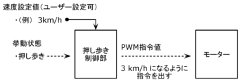
次に、押し歩き制御部222の行う制御について、説明する。図10は、実施の形態における押し歩き制御部222への入力と出力との例を示す図である。
[Control of push-walking controller]
Next, the control performed by the push-walking control section 222 will be described. FIG. 10 is a diagram showing an example of inputs and outputs to the push-walking control section 222 in the embodiment.

まず、挙動推定部221から出力された、電動アシスト自転車1の走行状態を示す判定結果が、押し歩きである場合に、その旨を示す情報が押し歩き制御部222に入力される。ここで、押し歩き制御部222には、挙動推定部221が電動アシスト自転車1の走行状態を押し歩きの状態であると判定したときだけ、挙動推定部221の判定結果が入力されるとしたが、これに限らない。押し歩き制御部222には、挙動推定部221が判定した結果が常に入力され、押し歩き制御部222が、当該判定結果が押し歩きであるか否かを判定してもよい。 First, when the determination result indicating the running state of the electrically power-assisted bicycle 1 output from the behavior estimating section 221 indicates that the bicycle is pushing and walking, information indicating that fact is input to the pushing-walking control section 222 . Here, the determination result of the behavior estimation unit 221 is input to the push-walking control unit 222 only when the behavior estimation unit 221 determines that the running state of the electrically power-assisted bicycle 1 is the state of pushing. , but not limited to this. The result determined by the behavior estimation unit 221 is always input to the push-walking control unit 222, and the push-walking control unit 222 may determine whether or not the determination result is push-walking.

次に、ユーザ2等が押し歩き制御が実現する車体10の速度を設定する。例えば、設定される車体10の速度は、3km/hでもよい。車体10の速度の設定は、ユーザが操作部40を通して、手動で行ってもよいし、サイクルコンピュータまたはスマートフォンアプリケーション等が自動で行ってもよい。また、車体10の速度は、押し歩き制御部222にあらかじめ設定されている速度が用いられてもよい。 Next, the user 2 or the like sets the speed of the vehicle body 10 at which the push-walking control is realized. For example, the set speed of the vehicle body 10 may be 3 km/h. The setting of the speed of the vehicle body 10 may be manually performed by the user through the operation unit 40, or may be automatically performed by a cycle computer, a smartphone application, or the like. Further, as the speed of the vehicle body 10, a speed preset in the push-walking control section 222 may be used.

なお、ここで、説明された押し歩き制御部222に挙動推定部221が判定した結果が入力される処理と、押し歩き制御が実現する車体10の速度の設定の処理は、この順で行われなくてもよく、説明された順序と逆の順序で行われてもよい。 Here, the process of inputting the result determined by the behavior estimating unit 221 to the pushing-walking control unit 222 and the process of setting the speed of the vehicle body 10 for realizing the pushing-walking control are performed in this order. It may not be present and may be performed in the reverse order to that described.

そして、押し歩き制御部222は、電動モータ21に、PWM(Pulse Width Modulation)指令値を送信する。ここで、PWM指令値は、設定された速度を実現するように電動モータ21を駆動することができる、デューティ比または周波数を変更させる信号である。例えば、速度設定値が3km/hである場合、車体10の速度が3km/hとなるように、電動モータ21を駆動するようなPWM指令値が、押し歩き制御部222から電動モータ21に送信される。 Then, the push-walking control unit 222 transmits a PWM (Pulse Width Modulation) command value to the electric motor 21 . Here, the PWM command value is a signal that changes the duty ratio or frequency that can drive the electric motor 21 to achieve the set speed. For example, when the speed setting value is 3 km/h, the PWM command value for driving the electric motor 21 is transmitted from the pushing control unit 222 to the electric motor 21 so that the speed of the vehicle body 10 becomes 3 km/h. be done.

図11は、実施の形態における押し歩き制御部222への入力と出力との別の例を示す図である。図11では、電動アシスト自転車1が圧力センサ45を備えている場合の押し歩き制御部への入力と出力の例が説明される。図10で説明されたように、まず、挙動推定部221から出力された、電動アシスト自転車1の走行状態を示す判定結果が、押し歩きである場合に、その旨を示す情報が押し歩き制御部222に入力される。挙動推定部221からの押し歩き制御部222への入力については、図10で説明された内容と同様である。 FIG. 11 is a diagram showing another example of inputs and outputs to the push-walking control section 222 in the embodiment. FIG. 11 illustrates an example of input and output to the push-walking control section when the power-assisted bicycle 1 is equipped with the pressure sensor 45 . As described with reference to FIG. 10 , first, when the determination result indicating the running state of the electrically power-assisted bicycle 1 output from the behavior estimation unit 221 is pushing and walking, the information indicating that fact is sent to the pushing and walking control unit. 222. The input from the behavior estimating unit 221 to the pushing-walking control unit 222 is the same as that described with reference to FIG.

次に、圧力センサ45から、検出された圧力のデータが押し歩き制御部222に入力される。 Next, data on the detected pressure is input from the pressure sensor 45 to the push-walking controller 222 .

なお、ここで、説明された押し歩き制御部222に挙動推定部221が判定した結果が入力される処理と、検出された圧力のデータが押し歩き制御部222に入力される処理は、この順で行われなくてもよく、説明された順序と逆の順序で行われてもよい。 Here, the process of inputting the result determined by the behavior estimation unit 221 to the pushing-walking control unit 222 and the process of inputting the detected pressure data to the pushing-walking control unit 222 are performed in this order. , and may be performed in the reverse order to that described.

そして、押し歩き制御部222は、電動モータ21に、PWM指令値を送信する。例えば、押し歩き制御部222に入力された、圧力センサで検知された圧力の値が0になるような、車体10の速度を実現するPWM指令値を送信する。つまり、押し歩き制御部222は、電動モータ21に、グリップ141に係る圧力によって実現される車体10の速度と同等の速度を実現するPWM指令値を送信する。なお、圧力は、グリップ141のユーザ2に対して前面に係る圧力だけでなく、グリップ141のユーザ2に対して後面に係る圧力でもよい。グリップ141のユーザ2に対して後面に係る圧力が検出されたときも、同様に、押し歩き制御部222は、電動モータ21に、グリップ141に係る圧力によって実現される車体10の速度と同等の速度を実現するPWM指令値を送信する。 Then, the push-walking control section 222 transmits the PWM command value to the electric motor 21 . For example, it transmits a PWM command value that realizes the speed of the vehicle body 10 such that the pressure value detected by the pressure sensor input to the push-walking control unit 222 becomes zero. That is, the push-walking control unit 222 transmits to the electric motor 21 a PWM command value that realizes a speed equivalent to the speed of the vehicle body 10 that is realized by the pressure applied to the grip 141 . Note that the pressure may be not only pressure applied to the front surface of the grip 141 against the user 2 but also pressure applied to the rear surface of the grip 141 against the user 2 . Similarly, when the pressure applied to the rear surface of the grip 141 to the user 2 is detected, the push-walking control unit 222 causes the electric motor 21 to adjust the speed equivalent to the speed of the vehicle body 10 realized by the pressure applied to the grip 141 . Send the PWM command value that realizes the speed.

また、ここで、押し歩き制御部222に入力された、圧力センサで検知された圧力の値が0になるような、車体10の速度を実現するPWM指令値を送信すると説明されたが、圧力センサで検知された圧力の値が所定の値より小さくなるような、車体10の速度を実現するPWM指令値を送信されてもよい。また、圧力センサで検知された圧力の値が検知された圧力よりも小さくなるような、車体10の速度を実現するPWM指令値を送信されてもよい。 Further, here, it was explained that the PWM command value that realizes the speed of the vehicle body 10 such that the value of the pressure detected by the pressure sensor input to the push-walking control unit 222 becomes 0 is transmitted. A PWM command value that realizes the speed of the vehicle body 10 such that the pressure value detected by the sensor becomes smaller than a predetermined value may be transmitted. Alternatively, a PWM command value may be transmitted that realizes the speed of the vehicle body 10 such that the pressure value detected by the pressure sensor is smaller than the detected pressure.

[電動アシスト自転車の走行状態の可視化]
図12は、実施の形態における電動アシスト自転車の制御方法によって判定された結果を可視化した例を示す図である。
[Visualization of the running state of an electrically assisted bicycle]
FIG. 12 is a diagram showing an example of visualizing the results determined by the control method for the power-assisted bicycle according to the embodiment.

挙動推定部221は、車体10の走行位置に関するデータを用いて、電動アシスト自転車1の移動履歴を割り出し、当該移動履歴を地図データ上に重ね合わせることで、電動アシスト自転車1の移動履歴の可視化を行ってもよい。電動アシスト自転車1の移動履歴は、電動アシスト自転車1に設置されたGPS(Global Positioning System)から送信される位置情報を、地図データ上に可視化することによって行われてもよい。 The behavior estimator 221 uses data about the running position of the vehicle body 10 to determine the movement history of the electrically power-assisted bicycle 1, and superimposes the movement history on the map data to visualize the movement history of the electrically power-assisted bicycle 1. you can go The movement history of the power-assisted bicycle 1 may be obtained by visualizing position information transmitted from a GPS (Global Positioning System) installed on the power-assisted bicycle 1 on map data.

また、電動アシスト自転車1の移動履歴は、電動アシスト自転車1に備えられたクランク回転センサ、ジャイロセンサ、および、加速度センサから出力されるデータに基づいて、挙動推定部221が移動距離および移動方向を割り出し、所定の基準点からの移動履歴を割り出してもよい。所定の基準点の設定にはGPSで計測された地点が用いられてもよいし、ユーザ2による手動で設定された地図上の地点が用いられてもよい。 The movement history of the electrically power-assisted bicycle 1 is obtained by the behavior estimator 221 based on the data output from the crank rotation sensor, the gyro sensor, and the acceleration sensor provided in the electrically power-assisted bicycle 1. A movement history from a predetermined reference point may be determined. A point measured by GPS may be used to set the predetermined reference point, or a point on the map manually set by the user 2 may be used.

当該移動履歴の地図データ上への重ね合わせは、既存の地図アプリケーションのAPI(Application Programming Interface)を利用して行われてもよい。既存の地図アプリケーションはインターネット上でオンラインで提供されているものを利用してもよく、記録媒体に記録されたソフトウェアとして提供されているものを利用してもよい。 The movement history may be superimposed on the map data using an API (Application Programming Interface) of an existing map application. An existing map application that is provided online on the Internet may be used, or one that is provided as software recorded on a recording medium may be used.

また、移動履歴の可視化においては、移動履歴の線種または色を変更することによって、電動アシスト自転車1の走行状態のそれぞれを表してもよい。ここで、電動アシスト自転車1の走行状態とは、例えば、停止、通常走行、押し歩きまたは惰性走行である。電動アシスト自転車1の可視化においては、電動アシスト自転車1の走行状態として、急ブレーキの状態が表示されてもよい。急ブレーキの状態は、電動アシスト自転車1の加速度の変化から判定されてもよい。 Further, in the visualization of the travel history, each running state of the electrically power-assisted bicycle 1 may be represented by changing the line type or color of the travel history. Here, the running state of the power-assisted bicycle 1 is, for example, stopped, normal running, pushing, or coasting. In the visualization of the power-assisted bicycle 1, a state of sudden braking may be displayed as the running state of the power-assisted bicycle 1. FIG. The state of sudden braking may be determined from changes in the acceleration of the electrically power-assisted bicycle 1 .

図12において、電動アシスト自転車1の移動履歴の可視化は、挙動推定部221が行うとして説明されたが、電動アシスト自転車1の移動履歴の可視化を行う別の処理部が設けられてもよい。当該処理部は、制御装置22に設けられてもよい。 In FIG. 12, it has been described that the movement history of the electrically power-assisted bicycle 1 is visualized by the behavior estimation unit 221, but another processing unit that visualizes the movement history of the electrically power-assisted bicycle 1 may be provided. The processing unit may be provided in the control device 22 .

また、当該処理部は、電動アシスト自転車1に備えられていなくてもよく、例えば、スマートフォンのアプリケーション、または、クラウドサーバ上のアプリケーション等で実現されてもよい。当該処理部がスマートフォンのアプリケーション等で実現される場合、スマートフォンのアプリケーションが、電動アシスト自転車1が外部のサーバ装置等に送信した、踏力センサ33、クランク回転センサ31、モータ回転センサ32、および圧力センサ45が検出したデータ、ならびに、挙動推定部221および押し歩き制御部222の出力した判定結果等を取得し、当該移動履歴の可視化処理を行う。スマートフォンのアプリケーションが取得する情報は上述したものの一部でもよいし、上述したものに限らず、他のデータも取得してもよい。 Also, the processing unit may not be provided in the electrically power-assisted bicycle 1, and may be realized by, for example, a smartphone application, an application on a cloud server, or the like. When the processing unit is realized by a smartphone application or the like, the smartphone application receives the pedal force sensor 33, the crank rotation sensor 31, the motor rotation sensor 32, and the pressure sensor, which are transmitted from the electrically power-assisted bicycle 1 to an external server device or the like. 45 and the determination results output from the behavior estimation unit 221 and the pushing-walking control unit 222 are acquired, and the movement history is visualized. The information acquired by the application of the smartphone may be part of the above-described information, and may also acquire other data in addition to the above-described information.

[電動アシスト自転車の制御方法]
ここで、上述した電動アシスト自転車の制御方法について、再度まとめて記載する。
[Method of controlling electric assist bicycle]
Here, the control method of the above-described power-assisted bicycle will be summarized again.

図13は、実施の形態における電動アシスト自転車の制御方法の処理を示すフローチャートである。 FIG. 13 is a flow chart showing the processing of the control method for the power-assisted bicycle according to the embodiment.

まず、第1検出部は、電動アシスト自転車1のペダル踏力またはクランク回転数と、車体速度とを検出する(ステップS200)。 First, the first detection section detects the pedaling force or the number of rotations of the crank of the electrically assisted bicycle 1 and the speed of the vehicle body (step S200).

次に、第1判定部は、電動アシスト自転車1が、停止、押し歩き、惰性走行および通常走行のうちの少なくとも一つの状態であるかを判定する(ステップS201)。 Next, the first determination unit determines whether the power-assisted bicycle 1 is in at least one state of stopping, pushing, coasting, and normal running (step S201).

続いて、第2判定部は、ステップS201での判定結果に基づいて、電動アシスト自転車1が、押し歩き、および、惰性走行のうちのいずれの状態であるかを判定する(ステップS202)。 Subsequently, the second determination unit determines whether the power-assisted bicycle 1 is in a state of pushing-walking or coasting based on the determination result in step S201 (step S202).

そして、電動アシスト部は、第2判定部が、電動アシスト自転車1が押し歩きの状態であると判定した場合、押し歩き用の電動アシストを行う(ステップS203)。また、電動アシスト部は、第1判定部が押し歩きの状態であると判定した場合にも、押し歩き用の電動アシストを行ってもよい。 Then, when the second determination unit determines that the power-assisted bicycle 1 is in the state of pushing and walking, the power assist section performs power assist for pushing and walking (step S203). Further, the electric assist section may perform the electric assist for pushing and walking even when the first determination section determines that the state is the state of pushing and walking.

[効果等]
電動アシスト自転車1の制御方法は、電動アシスト自転車1におけるペダル踏力またはクランク回転数と、車体速度とを検出する第1検出ステップと、ペダル踏力またはクランク回転数と、車体速度とを用いて、電動アシスト自転車1が、停止、押し歩き、惰性走行および通常走行のうちの少なくとも1つの状態であるかを判定する第1判定ステップと、第1判定ステップが行われてから所定時間経過した後に、第1判定ステップでの判定結果に基づいて、電動アシスト自転車1が押し歩き、および、惰性走行のうちのいずれの状態であるかを判定する第2判定ステップと、第2判定ステップで、電動アシスト自転車1が押し歩きの状態であると判定した場合に、電動アシスト自転車1が備えるモータを駆動して、押し歩きを支援するための電動アシストを行う電動アシストステップと、を含む。
[Effects, etc.]
The control method of the electrically power-assisted bicycle 1 includes a first detection step of detecting the pedaling force or the crank rotation speed of the electrically assisted bicycle 1 and the vehicle speed, and the pedaling force or the crank rotation speed and the vehicle body speed. a first determination step for determining whether the assisted bicycle 1 is in at least one state of stopping, pushing, coasting, and normal running; a second determination step for determining whether the electrically power-assisted bicycle 1 is in a state of pushing and running or coasting based on the determination result of the first determination step; and an electric assist step of driving the motor provided in the electric assist bicycle 1 to perform electric assist for assisting the pushing and walking when it is determined that step 1 is in the state of pushing and walking.

これにより、電動アシスト自転車1の制御方法は、ユーザ2からの回答の入力無しに、電動アシスト自転車1の走行状態を判定することができる。よって、電動アシスト自転車1の制御方法は、電動アシスト自転車1の走行状態に合わせたアシストを、より適切に電動アシスト自転車1に行わせることができる。 As a result, the control method of the power-assisted bicycle 1 can determine the running state of the power-assisted bicycle 1 without inputting an answer from the user 2 . Therefore, the method for controlling the electrically power-assisted bicycle 1 can cause the electrically power-assisted bicycle 1 to more appropriately provide assistance in accordance with the running state of the electrically power-assisted bicycle 1 .

また、例えば、電動アシスト自転車1の制御方法は、第2判定ステップでは、第1判定ステップでの判定結果に応じて、異なる判定基準を用いる。 Further, for example, in the control method of the power-assisted bicycle 1, in the second determination step, different determination criteria are used according to the determination result in the first determination step.

これにより、電動アシスト自転車1の制御方法は、判定が行われる直前の電動アシスト自転車1の走行状態を、判定処理の過程にフィードバックすることができる。よって、電動アシスト自転車1の制御方法は、より適切に電動アシスト自転車1の走行状態を判定することができる。 As a result, the control method for the electrically power-assisted bicycle 1 can feed back the running state of the electrically power-assisted bicycle 1 immediately before the determination is made to the determination process. Therefore, the control method of the power-assisted bicycle 1 can more appropriately determine the running state of the power-assisted bicycle 1 .

また、例えば、電動アシスト自転車の制御方法は、第2判定ステップでは、車体速度が判定値より大きいとき、前記電動アシスト自転車が前記惰性走行の状態であると判定し、車体速度が前記判定値以下のとき、電動アシスト自転車が押し歩きの状態であると判定し、第1判定ステップでの判定結果に応じて、異なる判定値を用いる。 Further, for example, in the method for controlling the electrically power-assisted bicycle, in the second determination step, when the vehicle body speed is greater than the determination value, it is determined that the electrically power-assisted bicycle is in the coasting state, and the vehicle body speed is equal to or less than the determination value. When , it is determined that the power-assisted bicycle is in the state of pushing and walking, and a different determination value is used according to the determination result in the first determination step.

これにより、電動アシスト自転車1の制御方法は、判定が行われる直前の電動アシスト自転車1の走行状態を、判定処理の過程で用いられる判定値にフィードバックすることができる。よって、電動アシスト自転車1の制御方法は、より適切に電動アシスト自転車1の走行状態を判定することができる。 As a result, the control method of the electrically power-assisted bicycle 1 can feed back the running state of the electrically power-assisted bicycle 1 immediately before the determination to the determination value used in the process of the determination process. Therefore, the control method of the power-assisted bicycle 1 can more appropriately determine the running state of the power-assisted bicycle 1 .

また、例えば、第1判定ステップで、電動アシスト自転車1が通常走行または惰性走行の状態であると判定されたときの判定値は、第1判定ステップで、電動アシスト自転車1が押し歩きの状態であると判定されたときの判定値よりも小さく、第1判定ステップで、電動アシスト自転車1が押し歩きの状態であると判定されたときの判定値は、第1判定ステップで、電動アシスト自転車1が停止の状態であると判定されたときの判定値よりも小さい。 Further, for example, when it is determined in the first determination step that the power-assisted bicycle 1 is in the state of normal running or inertia running, the determination value in the first determination step is When it is determined that the power-assisted bicycle 1 is in the state of pushing and walking in the first determination step, the power-assisted bicycle 1 is smaller than the determination value when it is determined that is in a stopped state.

これにより、電動アシスト自転車1の制御方法は、判定が行われる直前の電動アシスト自転車1の走行状態に応じて、適切な判定値を用いることができる。よって、電動アシスト自転車1の制御方法は、より適切に電動アシスト自転車1の走行状態を判定することができる。 As a result, the method of controlling the electrically power-assisted bicycle 1 can use an appropriate determination value according to the running state of the electrically power-assisted bicycle 1 immediately before the determination is made. Therefore, the control method of the power-assisted bicycle 1 can more appropriately determine the running state of the power-assisted bicycle 1 .

また、例えば、電動アシスト自転車1の制御方法は、さらに、電動アシスト自転車1のハンドル14に備えられた圧力センサ45から、ハンドル14にかかる所定以上の圧力を検出する第2検出ステップを含み、電動アシストステップでは、検出された圧力に基づいて、電動アシストを行う。 Further, for example, the control method of the electrically power-assisted bicycle 1 further includes a second detection step of detecting a predetermined pressure or more applied to the handle 14 from the pressure sensor 45 provided on the handle 14 of the electrically assisted bicycle 1, In the assist step, electric assist is performed based on the detected pressure.

これにより、電動アシスト自転車1の制御方法は、ユーザ2が電動アシスト自転車1の押し歩きをしていることを、圧力の測定によって検知させることができ、電動アシスト自転車1が、ユーザ2が電動アシスト自転車1の押し歩きをしていることを検知した場合、押し歩き用のアシストを、電動アシスト自転車1に行わせることができる。 As a result, the control method of the power-assisted bicycle 1 can detect that the user 2 is pushing the power-assisted bicycle 1 by measuring the pressure. When it is detected that the bicycle 1 is being pushed while walking, the power-assisted bicycle 1 can be made to assist the pushing while walking.

また、例えば、電動アシスト自転車1の制御方法は、第1判定ステップで、電動アシスト自転車1の状態が押し歩きの状態であると判定されたときに、第2判定ステップで、電動アシスト自転車1が押し歩き、および、惰性走行のうちのいずれの状態であるかを、判定値を用いて判定し、第1判定ステップで、電動アシスト自転車1の状態が通常走行または惰性走行の状態であると判定されたときに、第2判定ステップで、電動アシスト自転車1が惰性走行の状態であると判定し、第1判定ステップで、電動アシスト自転車1の状態が停止の状態であると判定されたときに、第2判定ステップで、電動アシスト自転車1が押し歩きの状態であると判定する。 Further, for example, in the control method of the power-assisted bicycle 1, when it is determined in the first determination step that the state of the power-assisted bicycle 1 is in the state of pushing and walking, in the second determination step, the power-assisted bicycle 1 is A determination value is used to determine whether the state is push-walking or inertia running, and in the first determination step, it is determined that the state of the power-assisted bicycle 1 is normal running or inertia running. When the second determination step determines that the power-assisted bicycle 1 is in the coasting state, and the first determination step determines that the power-assisted bicycle 1 is in the stopped state. , in the second determination step, it is determined that the power-assisted bicycle 1 is in a state of pushing and walking.

これにより、電動アシスト自転車1の制御方法は、判定が行われる直前の電動アシスト自転車1の走行状態が押し歩きのときに、電動アシスト自転車1の走行状態の判定を行うことができる。よって、電動アシスト自転車1の制御方法は、より簡便な方法で、電動アシスト自転車1の走行状態を判定することができる。 As a result, the control method of the electrically power-assisted bicycle 1 can determine the running state of the electrically power-assisted bicycle 1 when the running state of the electrically power-assisted bicycle 1 immediately before the determination is pushing and walking. Therefore, the control method of the power-assisted bicycle 1 can determine the running state of the power-assisted bicycle 1 by a simpler method.

また、電動アシスト自転車1の制御装置は、電動アシスト自転車1におけるペダル踏力またはクランク回転数と、車体速度とを取得する取得部223と、取得部223が取得したペダル踏力またはクランク回転数と、車体速度とを用いて、電動アシスト自転車1が、停止、押し歩き、惰性走行および通常走行のうちのいずれの状態であるかを判定する第1判定部と、第1判定部での判定結果に基づいて、電動アシスト自転車が押し歩き、および、惰性走行のうちのいずれの状態であるかを判定する第2判定部と、第2判定部で、電動アシスト自転車1が押し歩きの状態であると判定した場合に、電動アシスト自転車1が備えるモータを駆動して、押し歩きを支援するための電動アシストを行う電動アシスト部と、を備える。 In addition, the control device of the electrically assisted bicycle 1 includes an acquisition unit 223 that acquires the pedal effort or the crank rotation speed and the vehicle speed of the electrically assisted bicycle 1, the pedal effort or the crank rotation speed acquired by the acquisition unit 223, the vehicle body a first determination unit that determines whether the power-assisted bicycle 1 is in a stopped state, a push-walking state, an inertia running state, or a normal running state using the speed and the speed; a second determination unit that determines whether the electrically power-assisted bicycle 1 is in the state of pushing and walking, and the second determination unit determines that the electrically power-assisted bicycle 1 is in the state of pushing and walking. and an electric assist unit that drives a motor included in the electric assist bicycle 1 to perform electric assist for assisting pushing while walking when the electric assist bicycle 1 is pushed.

これにより、電動アシスト自転車1の制御装置は、上記電動アシスト自転車1の制御方法と同様の効果を奏することができる。 As a result, the control device for the power-assisted bicycle 1 can achieve the same effects as the control method for the power-assisted bicycle 1 described above.

また、電動アシスト自転車1は、電動アシスト自転車1におけるペダル踏力またはクランク回転数と、車体速度とを検出する第1検出部と、ペダル踏力またはクランク回転数と、車体速度とを用いて、電動アシスト自転車1が、停止、押し歩き、惰性走行および通常走行のうちのいずれの状態であるかを判定する第1判定部と、第1判定部での判定結果に基づいて、電動アシスト自転車1が押し歩き、および、惰性走行のうちのいずれの状態であるかを判定する第2判定部と、第2判定部で、電動アシスト自転車1が押し歩きの状態であると判定した場合に、電動アシスト自転車1が備えるモータを駆動して、押し歩きを支援するための電動アシストを行う電動アシスト部と、を備える。 In addition, the electrically power-assisted bicycle 1 uses a first detection unit that detects the pedaling force or the crank rotation speed and the vehicle speed of the electrically power-assisted bicycle 1, the pedaling force or the crank rotation speed, and the vehicle body speed to detect the electric assist A first determination unit that determines whether the bicycle 1 is in a state of stopping, pushing while walking, inertia running, or normal running; A second determination unit that determines whether the state is one of walking and inertia running; and an electric assist unit that drives a motor included in 1 to perform electric assist for assisting pushing while walking.

これにより、電動アシスト自転車1は、上記電動アシスト自転車1の制御方法と同様の効果を奏することができる。 As a result, the power-assisted bicycle 1 can achieve the same effects as the control method of the power-assisted bicycle 1 described above.

また、例えば、電動アシスト自転車1において、第1判定部または第2判定部は、電動アシスト自転車1が備える電動アシストユニットに搭載される。 Further, for example, in the power-assisted bicycle 1 , the first determination section or the second determination section is mounted in the power-assist unit provided in the power-assisted bicycle 1 .

これにより、電動アシスト自転車1は、本体において、自身の走行状態を判定することができる。 As a result, the power-assisted bicycle 1 can determine its own running state on the main body.

また、例えば、電動アシスト自転車1において、第1判定部または第2判定部は、手元スイッチまたはサイクルコンピュータに搭載される。 Further, for example, in the power-assisted bicycle 1, the first determination section or the second determination section is mounted on a hand switch or cycle computer.

これにより、電動アシスト自転車1は、本体の付属品において、自身の走行状態を判定することができる。 As a result, the power-assisted bicycle 1 can determine its own running state in the accessories of the main body.

[その他]
また、実施の形態において、ユニット、装置、部材、または、部の全部、または、一部、または、図4に示されるブロック図の機能ブロックの全部、または、一部は、半導体装置、半導体集積回路(IC(Integrated Circuit))、または、大規模集積回路(LSI(Large Scale Integration))を含む一つ、または、複数の電子回路によって実行されてもよい。IC、または、LSIは、一つのチップ(システムLSI)に集積されてもよいし、複数のチップを組み合わせて一つのシステム(チップセット)に構成されてもよい。例えば、画面の表示処理以外の機能ブロックは、一つのチップに集積されてもよい。ここでは、IC、または、LSIと呼んでいるが、集積の度合いによって呼び方が変わり、VLSI(Very Large Scale Integration)、若しくはULSI(Ultra Large Scale Integration)と呼ばれるものであってもよい。LSIの製造後にプログラムされる電子ヒューズ(eFuse)を搭載したシステムLSI、または、FPGA(Field Programmable Gate Array)、または、LSI内部の接続関係の再構成、または、LSI内部の論理回路の動的な再構成ができるリコンフィギュラブルデバイス(reconfigurable device)も同じ目的で使うことができる。
[others]
Further, in the embodiments, all or part of the units, devices, members, or sections, or all or part of the functional blocks in the block diagram shown in FIG. It may be implemented by one or more electronic circuits including a circuit (IC (Integrated Circuit)) or a large scale integration (LSI (Large Scale Integration)). The IC or LSI may be integrated into one chip (system LSI), or may be configured into one system (chipset) by combining a plurality of chips. For example, functional blocks other than screen display processing may be integrated into one chip. Here, they are called ICs or LSIs, but they may be called VLSI (Very Large Scale Integration) or ULSI (Ultra Large Scale Integration) depending on the degree of integration. A system LSI equipped with an electronic fuse (eFuse) that is programmed after the LSI is manufactured, or an FPGA (Field Programmable Gate Array), or a reconfiguration of the connection relationship inside the LSI, or a dynamic logic circuit inside the LSI. A reconfigurable device that can be reconfigured can also be used for the same purpose.

さらに、ユニット、装置、部材、または、部の全部、または、一部の機能、または、操作は、ソフトウエア処理によって実行することが可能である。この場合、ソフトウエアは一つ、または、複数のROM、光学ディスク、ハードディスクドライブなどの非一時的記録媒体に記録され、ソフトウエアがマイクロコントローラ(MCU(microcontroller))、または、マイクロプロセッサ(MPU(microprocessor))等の処理装置(processor)によって実行されたときに、そのソフトウエアで特定された機能が処理装置および周辺装置によって実行される。システム、または、装置は、ソフトウエアが記録されている一つ、または、複数の非一時的記録媒体、処理装置、および必要とされるハードウェアデバイス、例えばデジタルインターフェース、を備えていても良い。 Further, all or some functions or operations of units, devices, members or sections may be performed by software processing. In this case, the software is recorded in one or more non-transitory recording media such as ROM, optical disk, hard disk drive, etc. When executed by a processor such as a microprocessor, the functions specified in the software are performed by the processor and peripheral devices. A system or apparatus may comprise one or more non-transitory storage media on which software is recorded, a processing unit and required hardware devices such as a digital interface.

また、上記各実施の形態における制御装置22は、プロセッサとメモリとを有し、メモリには、図9または図13に示すフローチャートの各ステップを実行するためのプログラムが記憶されていてもよい。この場合、プロセッサは、そのメモリに記憶されているプログラムを実行する。 Further, the control device 22 in each of the above embodiments may have a processor and a memory, and the memory may store a program for executing each step of the flow chart shown in FIG. 9 or 13 . In this case, the processor executes programs stored in its memory.

1 電動アシスト自転車
10 車体
20 モータ駆動ユニット
31 クランク回転センサ
32 モータ回転センサ
33 踏力センサ
40 操作部
45 圧力センサ
221 挙動推定部
222 押し歩き制御部
223 取得部
1 Power-assisted bicycle 10 Body 20 Motor drive unit 31 Crank rotation sensor 32 Motor rotation sensor 33 Pedal force sensor 40 Operation unit 45 Pressure sensor 221 Behavior estimation unit 222 Pushing control unit 223 Acquisition unit

Claims (10)

電動アシスト自転車の制御方法であって、
前記電動アシスト自転車におけるペダル踏力またはクランク回転数と、車体速度とを検出する第1検出ステップと、
前記ペダル踏力または前記クランク回転数と、前記車体速度とを用いて、前記電動アシスト自転車が、停止、押し歩き、惰性走行および通常走行のうちの少なくとも1つの状態であるかを判定する第1判定ステップと、
前記第1判定ステップが行われてから所定時間経過した後に、前記第1判定ステップでの判定結果に基づいて、前記電動アシスト自転車が前記押し歩き、および、前記惰性走行のうちのいずれの状態であるかを判定する第2判定ステップと、
前記電動アシスト自転車が前記押し歩きの状態であると前記第2判定ステップで判定した場合に、前記電動アシスト自転車が備えるモータを駆動して、前記押し歩きを支援するための電動アシストを行う電動アシストステップと、を含む、
電動アシスト自転車の制御方法。
A control method for an electrically assisted bicycle,
a first detection step of detecting the pedaling force or the number of rotations of the crank and the speed of the vehicle body of the electrically assisted bicycle;
A first determination for determining whether the power-assisted bicycle is in at least one state of stopping, pushing, coasting, and normal running, using the pedaling force or the crank rotation speed, and the vehicle body speed. a step;
After a predetermined period of time has elapsed since the first determination step was performed, the power-assisted bicycle is in either the pushing-walking state or the coasting state based on the determination result in the first determining step. a second determination step of determining whether there is
When it is determined in the second determination step that the electrically power-assisted bicycle is in the state of pushing and walking, a motor provided in the electrically power-assisted bicycle is driven to perform electric assist for assisting the pushing-walking. including steps and
A control method for an electrically assisted bicycle.
前記第2判定ステップでは、前記第1判定ステップでの判定結果に応じて、異なる判定基準を用いて、前記電動アシスト自転車が前記押し歩き、および、前記惰性走行のうちのいずれの状態であるかを判定する、
請求項1に記載の電動アシスト自転車の制御方法。
In the second determination step, depending on the determination result in the first determination step, different determination criteria are used to determine whether the power-assisted bicycle is in one of the pushing-walking state and the coasting state. determine the
A control method for an electrically assisted bicycle according to claim 1.
前記第2判定ステップでは、
前記車体速度が判定値より大きいとき、前記電動アシスト自転車が前記惰性走行の状態であると判定し、
前記車体速度が前記判定値以下のとき、前記電動アシスト自転車が前記押し歩きの状態であると判定し、
前記第1判定ステップでの判定結果に応じて、異なる前記判定値を用いて、前記電動アシスト自転車が前記押し歩き、および、前記惰性走行のうちのいずれの状態であるかを判定する、
請求項2に記載の電動アシスト自転車の制御方法。
In the second determination step,
determining that the electrically power-assisted bicycle is in the coasting state when the vehicle body speed is greater than a determination value;
determining that the electrically power-assisted bicycle is in the state of pushing and walking when the vehicle body speed is equal to or less than the determination value;
Determining whether the electrically power-assisted bicycle is in one of the pushing-walking state and the inertial running state using a different determination value according to the determination result of the first determination step;
A control method for an electrically assisted bicycle according to claim 2.
前記第1判定ステップで、前記電動アシスト自転車が前記通常走行または前記惰性走行の状態であると判定されたときの前記判定値は、前記第1判定ステップで、前記電動アシスト自転車が前記押し歩きの状態であると判定されたときの前記判定値よりも小さく、
前記第1判定ステップで、前記電動アシスト自転車が前記押し歩きの状態であると判定されたときの前記判定値は、前記第1判定ステップで、前記電動アシスト自転車が前記停止の状態であると判定されたときの前記判定値よりも小さい、
請求項3に記載の電動アシスト自転車の制御方法。
When it is determined in the first determination step that the power-assisted bicycle is in the normal running state or the inertia running state, the determination value in the first determination step is that the power-assisted bicycle is in the state of pushing and walking. smaller than the determination value when it is determined to be in a state,
The determination value when it is determined in the first determination step that the power-assisted bicycle is in the state of pushing and walking is determined in the first determination step to be that the power-assisted bicycle is in the state of stopping. is smaller than the judgment value when
A control method for an electrically assisted bicycle according to claim 3.
さらに、前記電動アシスト自転車のハンドルに備えられた圧力センサから、前記ハンドルにかかる所定以上の圧力を検出する第2検出ステップを含み、
前記電動アシストステップでは、検出された前記圧力に基づいて、前記電動アシストを行う、
請求項1~4のいずれか1項に記載の電動アシスト自転車の制御方法。
Furthermore, a second detection step of detecting a predetermined pressure or more applied to the handle from a pressure sensor provided on the handle of the electrically assisted bicycle,
In the electric assist step, the electric assist is performed based on the detected pressure.
A control method for a power-assisted bicycle according to any one of claims 1 to 4.
前記第1判定ステップで、前記電動アシスト自転車の状態が前記押し歩きの状態であると判定されたときに、前記第2判定ステップで、前記電動アシスト自転車が前記押し歩き、および、前記惰性走行のうちのいずれの状態であるかを、判定値を用いて判定し、
前記第1判定ステップで、前記電動アシスト自転車の状態が前記通常走行または前記惰性走行の状態であると判定されたときに、前記第2判定ステップで、前記電動アシスト自転車が前記惰性走行の状態であると判定し、
前記第1判定ステップで、前記電動アシスト自転車の状態が前記停止の状態であると判定されたときに、前記第2判定ステップで、前記電動アシスト自転車が前記押し歩きの状態であると判定する、
請求項1に記載の電動アシスト自転車の制御方法。
When it is determined in the first determination step that the state of the power-assisted bicycle is the state of pushing and walking, in the second determination step, the power-assisted bicycle is in the state of pushing and walking and the inertia running. Use the judgment value to determine which state of the
When it is determined in the first determination step that the state of the power-assisted bicycle is in the normal running state or the inertia running state, in the second determination step, the power-assisted bicycle is in the inertia running state. determine that there is
When the state of the power-assisted bicycle is determined to be the stopped state in the first determination step, the power-assisted bicycle is determined to be in the state of pushing and walking in the second determination step.
A control method for an electrically assisted bicycle according to claim 1.
電動アシスト自転車の制御装置であって、
前記電動アシスト自転車におけるペダル踏力またはクランク回転数と、車体速度とを取得する取得部と、
前記取得部が取得した前記ペダル踏力または前記クランク回転数と、前記車体速度とを用いて、前記電動アシスト自転車が、停止、押し歩き、惰性走行および通常走行のうちのいずれの状態であるかを判定する第1判定部と、
前記第1判定部での判定結果に基づいて、前記電動アシスト自転車が前記押し歩き、および、前記惰性走行のうちのいずれの状態であるかを判定する第2判定部と、
前記第2判定部で、前記電動アシスト自転車が前記押し歩きの状態であると判定した場合に、前記電動アシスト自転車が備えるモータを駆動して、前記押し歩きを支援するための電動アシストを行う電動アシスト部と、を備える、
電動アシスト自転車の制御装置。
A control device for an electrically assisted bicycle,
an acquisition unit that acquires a pedal effort or crank rotation speed and a vehicle body speed of the electrically assisted bicycle;
Using the pedal depression force or the crank rotation speed acquired by the acquisition unit and the vehicle body speed, it is determined whether the power-assisted bicycle is in a stopped state, a push-walking state, an inertia running state, or a normal running state. a first determination unit that determines;
a second determination unit that determines, based on the result of determination by the first determination unit, whether the electrically power-assisted bicycle is in one of the pushing-walking state and the coasting state;
When the second determining unit determines that the electrically power-assisted bicycle is in the state of pushing and walking, an electric motor that drives a motor included in the electrically power-assisted bicycle to perform electric assist for assisting the pushing-walking. an assist section,
A control device for an electrically assisted bicycle.
電動アシスト自転車であって、
前記電動アシスト自転車におけるペダル踏力またはクランク回転数と、車体速度とを検出する第1検出部と、
前記ペダル踏力または前記クランク回転数と、前記車体速度とを用いて、前記電動アシスト自転車が、停止、押し歩き、惰性走行および通常走行のうちのいずれの状態であるかを判定する第1判定部と、
前記第1判定部での判定結果に基づいて、前記電動アシスト自転車が前記押し歩き、および、前記惰性走行のうちのいずれの状態であるかを判定する第2判定部と、
前記第2判定部で、前記電動アシスト自転車が前記押し歩きの状態であると判定した場合に、前記電動アシスト自転車が備えるモータを駆動して、前記押し歩きを支援するための電動アシストを行う電動アシスト部と、を備える、
電動アシスト自転車。
An electrically assisted bicycle,
a first detection unit that detects the pedaling force or the number of rotations of the crank and the speed of the vehicle body of the electrically assisted bicycle;
A first determination unit that determines whether the power-assisted bicycle is in a stopped state, a push-walking state, an inertia running state, or a normal running state, using the pedaling force or the crank rotation speed, and the vehicle body speed. and,
a second determination unit that determines, based on the result of determination by the first determination unit, whether the electrically power-assisted bicycle is in one of the pushing-walking state and the coasting state;
When the second determining unit determines that the electrically power-assisted bicycle is in the state of pushing and walking, an electric motor that drives a motor included in the electrically power-assisted bicycle to perform electric assist for assisting the pushing-walking. an assist section,
electric assist bicycle.
前記第1判定部または前記第2判定部は、前記電動アシスト自転車が備える電動アシストユニットに搭載される、
請求項8に記載の電動アシスト自転車。
The first determination section or the second determination section is mounted on an electric assist unit included in the electric assist bicycle,
The electrically assisted bicycle according to claim 8.
前記第1判定部または前記第2判定部は、手元スイッチまたはサイクルコンピュータに搭載される、
請求項8に記載の電動アシスト自転車。
The first determination unit or the second determination unit is mounted on a hand switch or a cycle computer,
The electrically assisted bicycle according to claim 8.
JP2019229825A 2019-12-20 2019-12-20 Electric assist bicycle control method, electric assist bicycle control device, and electric assist bicycle Active JP7285452B2 (en)

Priority Applications (1)

Application Number Priority Date Filing Date Title
JP2019229825A JP7285452B2 (en) 2019-12-20 2019-12-20 Electric assist bicycle control method, electric assist bicycle control device, and electric assist bicycle

Applications Claiming Priority (1)

Application Number Priority Date Filing Date Title
JP2019229825A JP7285452B2 (en) 2019-12-20 2019-12-20 Electric assist bicycle control method, electric assist bicycle control device, and electric assist bicycle

Publications (2)

Publication Number Publication Date
JP2021098389A JP2021098389A (en) 2021-07-01
JP7285452B2 true JP7285452B2 (en) 2023-06-02

Family

ID=76540651

Family Applications (1)

Application Number Title Priority Date Filing Date
JP2019229825A Active JP7285452B2 (en) 2019-12-20 2019-12-20 Electric assist bicycle control method, electric assist bicycle control device, and electric assist bicycle

Country Status (1)

Country Link
JP (1) JP7285452B2 (en)

Families Citing this family (2)

* Cited by examiner, † Cited by third party
Publication number Priority date Publication date Assignee Title
CN113859418A (en) * 2021-10-27 2021-12-31 深圳爱玛智行科技有限公司 Power-assisted push control system and method for electric vehicle
JP2023172536A (en) * 2022-05-24 2023-12-06 キヤノン株式会社 Communication device, communication control method, and computer program

Citations (7)

* Cited by examiner, † Cited by third party
Publication number Priority date Publication date Assignee Title
JP2000168672A (en) 1998-12-04 2000-06-20 Suzuki Motor Corp Electric motor-assisted bicycle
JP2007191114A (en) 2006-01-23 2007-08-02 Matsushita Electric Ind Co Ltd Vehicle with power assist
JP4358988B2 (en) 1997-10-21 2009-11-04 ノバルティス アクチエンゲゼルシャフト Single mold centering
WO2013132535A1 (en) 2012-03-08 2013-09-12 パナソニック株式会社 Electric bicycle
JP2017088155A (en) 2015-11-09 2017-05-25 太陽誘電株式会社 Regeneration control device of electric motor, regeneration driving device of electric motor, and electric auxiliary vehicle
JP2019177719A (en) 2018-03-30 2019-10-17 パナソニックIpマネジメント株式会社 Electric bicycle and control method of electric bicycle
JP2019209849A (en) 2018-06-05 2019-12-12 パナソニックIpマネジメント株式会社 Motor unit and electric bicycle

Patent Citations (7)

* Cited by examiner, † Cited by third party
Publication number Priority date Publication date Assignee Title
JP4358988B2 (en) 1997-10-21 2009-11-04 ノバルティス アクチエンゲゼルシャフト Single mold centering
JP2000168672A (en) 1998-12-04 2000-06-20 Suzuki Motor Corp Electric motor-assisted bicycle
JP2007191114A (en) 2006-01-23 2007-08-02 Matsushita Electric Ind Co Ltd Vehicle with power assist
WO2013132535A1 (en) 2012-03-08 2013-09-12 パナソニック株式会社 Electric bicycle
JP2017088155A (en) 2015-11-09 2017-05-25 太陽誘電株式会社 Regeneration control device of electric motor, regeneration driving device of electric motor, and electric auxiliary vehicle
JP2019177719A (en) 2018-03-30 2019-10-17 パナソニックIpマネジメント株式会社 Electric bicycle and control method of electric bicycle
JP2019209849A (en) 2018-06-05 2019-12-12 パナソニックIpマネジメント株式会社 Motor unit and electric bicycle

Non-Patent Citations (1)

* Cited by examiner, † Cited by third party
Title
オーナーズマニュアル RIDE+ 電動自転車,日本,トレックジャパン株式会社,2017年

Also Published As

Publication number Publication date
JP2021098389A (en) 2021-07-01

Similar Documents

Publication Publication Date Title
JP5575938B1 (en) Bicycle control device
US20190300115A1 (en) Human-powered vehicle control device
US11124266B2 (en) Human-powered vehicle control device
KR101516075B1 (en) Eletricity bike control system and method for control the same
JP7249540B2 (en) FAILURE DETECTION DEVICE, ELECTRIC BICYCLE, AND FAILURE DETECTION METHOD
US11124267B2 (en) Human-powered vehicle control device
JP7113323B2 (en) Electric bicycle and control method of electric bicycle
JP7285452B2 (en) Electric assist bicycle control method, electric assist bicycle control device, and electric assist bicycle
US20230034689A1 (en) Human-powered vehicle control device, suspension system, and human-powered vehicle
US10604210B2 (en) Human-powered vehicle control device
JP2022104358A (en) Control device for human-powered vehicle and control system for human-powered vehicle
JP2016088374A (en) Electric power-assisted bicycle
US11377166B2 (en) Human-powered vehicle control device
JP7142265B2 (en) Electric bicycle and control method of electric bicycle
WO2022172424A1 (en) Electrically powered bicycle control method, electrically powered bicycle control device, and electrically powered bicycle
JP6475108B2 (en) Bicycle with electric motor
JP7126139B2 (en) Electric bicycle and its control method
US20220204129A1 (en) Control device for human-powered vehicle
JP7108915B2 (en) Electric bicycles and methods of controlling electric bicycles
JP7125889B2 (en) Manpowered vehicle controller
JP2020029207A (en) Control device for man power driving vehicle
JP6738400B2 (en) Bicycle with electric motor
JP7324694B2 (en) Discrimination device for human-powered vehicle and control device for human-powered vehicle
JP2023151107A (en) Control device for man power drive vehicle
JP2021091291A (en) Electric bicycle and control device for electric bicycle

Legal Events

Date Code Title Description
A621 Written request for application examination

Free format text: JAPANESE INTERMEDIATE CODE: A621

Effective date: 20221017

A977 Report on retrieval

Free format text: JAPANESE INTERMEDIATE CODE: A971007

Effective date: 20230412

TRDD Decision of grant or rejection written
A01 Written decision to grant a patent or to grant a registration (utility model)

Free format text: JAPANESE INTERMEDIATE CODE: A01

Effective date: 20230425

A61 First payment of annual fees (during grant procedure)

Free format text: JAPANESE INTERMEDIATE CODE: A61

Effective date: 20230508

R151 Written notification of patent or utility model registration

Ref document number: 7285452

Country of ref document: JP

Free format text: JAPANESE INTERMEDIATE CODE: R151