US9419058B1 - Memory device with comb-shaped electrode having a plurality of electrode fingers and method of making thereof - Google Patents
Memory device with comb-shaped electrode having a plurality of electrode fingers and method of making thereof Download PDFInfo
- Publication number
- US9419058B1 US9419058B1 US14/614,709 US201514614709A US9419058B1 US 9419058 B1 US9419058 B1 US 9419058B1 US 201514614709 A US201514614709 A US 201514614709A US 9419058 B1 US9419058 B1 US 9419058B1
- Authority
- US
- United States
- Prior art keywords
- bit line
- electrically conductive
- transistor
- memory cell
- local bit
- Prior art date
- Legal status (The legal status is an assumption and is not a legal conclusion. Google has not performed a legal analysis and makes no representation as to the accuracy of the status listed.)
- Expired - Fee Related
Links
- 238000004519 manufacturing process Methods 0.000 title claims description 12
- 210000001520 comb Anatomy 0.000 claims abstract description 47
- 125000006850 spacer group Chemical group 0.000 claims description 41
- 239000004065 semiconductor Substances 0.000 claims description 32
- 238000000034 method Methods 0.000 claims description 29
- 239000000463 material Substances 0.000 claims description 25
- 238000005530 etching Methods 0.000 claims description 15
- 239000010409 thin film Substances 0.000 claims description 11
- 230000005669 field effect Effects 0.000 abstract 1
- 239000010410 layer Substances 0.000 description 140
- 229910052751 metal Inorganic materials 0.000 description 12
- 239000002184 metal Substances 0.000 description 12
- VYPSYNLAJGMNEJ-UHFFFAOYSA-N Silicium dioxide Chemical compound O=[Si]=O VYPSYNLAJGMNEJ-UHFFFAOYSA-N 0.000 description 9
- 229910052814 silicon oxide Inorganic materials 0.000 description 9
- 229910052581 Si3N4 Inorganic materials 0.000 description 7
- HQVNEWCFYHHQES-UHFFFAOYSA-N silicon nitride Chemical compound N12[Si]34N5[Si]62N3[Si]51N64 HQVNEWCFYHHQES-UHFFFAOYSA-N 0.000 description 7
- 239000000758 substrate Substances 0.000 description 7
- -1 TiOx Chemical class 0.000 description 5
- 239000004020 conductor Substances 0.000 description 5
- 229910052721 tungsten Inorganic materials 0.000 description 5
- 239000010937 tungsten Substances 0.000 description 5
- 230000004888 barrier function Effects 0.000 description 4
- 230000009977 dual effect Effects 0.000 description 4
- 229910044991 metal oxide Inorganic materials 0.000 description 4
- 150000004706 metal oxides Chemical class 0.000 description 4
- XUIMIQQOPSSXEZ-UHFFFAOYSA-N Silicon Chemical compound [Si] XUIMIQQOPSSXEZ-UHFFFAOYSA-N 0.000 description 3
- ATJFFYVFTNAWJD-UHFFFAOYSA-N Tin Chemical compound [Sn] ATJFFYVFTNAWJD-UHFFFAOYSA-N 0.000 description 3
- 238000002955 isolation Methods 0.000 description 3
- 238000000059 patterning Methods 0.000 description 3
- 238000000206 photolithography Methods 0.000 description 3
- 229910052710 silicon Inorganic materials 0.000 description 3
- 239000010703 silicon Substances 0.000 description 3
- WFKWXMTUELFFGS-UHFFFAOYSA-N tungsten Chemical compound [W] WFKWXMTUELFFGS-UHFFFAOYSA-N 0.000 description 3
- RYGMFSIKBFXOCR-UHFFFAOYSA-N Copper Chemical compound [Cu] RYGMFSIKBFXOCR-UHFFFAOYSA-N 0.000 description 2
- RTAQQCXQSZGOHL-UHFFFAOYSA-N Titanium Chemical compound [Ti] RTAQQCXQSZGOHL-UHFFFAOYSA-N 0.000 description 2
- NRTOMJZYCJJWKI-UHFFFAOYSA-N Titanium nitride Chemical compound [Ti]#N NRTOMJZYCJJWKI-UHFFFAOYSA-N 0.000 description 2
- 229910045601 alloy Inorganic materials 0.000 description 2
- 239000000956 alloy Substances 0.000 description 2
- 229910052782 aluminium Inorganic materials 0.000 description 2
- XAGFODPZIPBFFR-UHFFFAOYSA-N aluminium Chemical compound [Al] XAGFODPZIPBFFR-UHFFFAOYSA-N 0.000 description 2
- 150000004770 chalcogenides Chemical class 0.000 description 2
- 239000002800 charge carrier Substances 0.000 description 2
- 229910052802 copper Inorganic materials 0.000 description 2
- 239000010949 copper Substances 0.000 description 2
- 239000011810 insulating material Substances 0.000 description 2
- 238000012986 modification Methods 0.000 description 2
- 230000004048 modification Effects 0.000 description 2
- 150000004767 nitrides Chemical class 0.000 description 2
- 229910021420 polycrystalline silicon Inorganic materials 0.000 description 2
- 229920005591 polysilicon Polymers 0.000 description 2
- 239000010936 titanium Substances 0.000 description 2
- 229910052719 titanium Inorganic materials 0.000 description 2
- 229910000763 AgInSbTe Inorganic materials 0.000 description 1
- 229910002451 CoOx Inorganic materials 0.000 description 1
- 229910005542 GaSb Inorganic materials 0.000 description 1
- 229910005872 GeSb Inorganic materials 0.000 description 1
- 229910005900 GeTe Inorganic materials 0.000 description 1
- 229910016978 MnOx Inorganic materials 0.000 description 1
- 229910005855 NiOx Inorganic materials 0.000 description 1
- OAICVXFJPJFONN-UHFFFAOYSA-N Phosphorus Chemical compound [P] OAICVXFJPJFONN-UHFFFAOYSA-N 0.000 description 1
- 229910003070 TaOx Inorganic materials 0.000 description 1
- 229910003087 TiOx Inorganic materials 0.000 description 1
- 229910007477 ZnMn2O4 Inorganic materials 0.000 description 1
- 229910007667 ZnOx Inorganic materials 0.000 description 1
- 229910003134 ZrOx Inorganic materials 0.000 description 1
- 229910052785 arsenic Inorganic materials 0.000 description 1
- RQNWIZPPADIBDY-UHFFFAOYSA-N arsenic atom Chemical compound [As] RQNWIZPPADIBDY-UHFFFAOYSA-N 0.000 description 1
- 239000005387 chalcogenide glass Substances 0.000 description 1
- 230000008021 deposition Effects 0.000 description 1
- 239000012777 electrically insulating material Substances 0.000 description 1
- 239000000945 filler Substances 0.000 description 1
- CJNBYAVZURUTKZ-UHFFFAOYSA-N hafnium(IV) oxide Inorganic materials O=[Hf]=O CJNBYAVZURUTKZ-UHFFFAOYSA-N 0.000 description 1
- 239000011229 interlayer Substances 0.000 description 1
- 238000005468 ion implantation Methods 0.000 description 1
- 230000001788 irregular Effects 0.000 description 1
- 230000007257 malfunction Effects 0.000 description 1
- 230000000116 mitigating effect Effects 0.000 description 1
- 229910052698 phosphorus Inorganic materials 0.000 description 1
- 239000011574 phosphorus Substances 0.000 description 1
- 238000007517 polishing process Methods 0.000 description 1
- 230000004044 response Effects 0.000 description 1
- 230000002441 reversible effect Effects 0.000 description 1
- 239000000126 substance Substances 0.000 description 1
- HLLICFJUWSZHRJ-UHFFFAOYSA-N tioxidazole Chemical compound CCCOC1=CC=C2N=C(NC(=O)OC)SC2=C1 HLLICFJUWSZHRJ-UHFFFAOYSA-N 0.000 description 1
Images


Classifications
-
- H—ELECTRICITY
- H10—SEMICONDUCTOR DEVICES; ELECTRIC SOLID-STATE DEVICES NOT OTHERWISE PROVIDED FOR
- H10B—ELECTRONIC MEMORY DEVICES
- H10B63/00—Resistance change memory devices, e.g. resistive RAM [ReRAM] devices
- H10B63/80—Arrangements comprising multiple bistable or multi-stable switching components of the same type on a plane parallel to the substrate, e.g. cross-point arrays
- H10B63/84—Arrangements comprising multiple bistable or multi-stable switching components of the same type on a plane parallel to the substrate, e.g. cross-point arrays arranged in a direction perpendicular to the substrate, e.g. 3D cell arrays
- H10B63/845—Arrangements comprising multiple bistable or multi-stable switching components of the same type on a plane parallel to the substrate, e.g. cross-point arrays arranged in a direction perpendicular to the substrate, e.g. 3D cell arrays the switching components being connected to a common vertical conductor
-
- H—ELECTRICITY
- H10—SEMICONDUCTOR DEVICES; ELECTRIC SOLID-STATE DEVICES NOT OTHERWISE PROVIDED FOR
- H10B—ELECTRONIC MEMORY DEVICES
- H10B63/00—Resistance change memory devices, e.g. resistive RAM [ReRAM] devices
- H10B63/30—Resistance change memory devices, e.g. resistive RAM [ReRAM] devices comprising selection components having three or more electrodes, e.g. transistors
-
- H01L27/249—
-
- H01L27/2436—
-
- H01L27/2454—
-
- H01L45/16—
-
- H—ELECTRICITY
- H10—SEMICONDUCTOR DEVICES; ELECTRIC SOLID-STATE DEVICES NOT OTHERWISE PROVIDED FOR
- H10B—ELECTRONIC MEMORY DEVICES
- H10B63/00—Resistance change memory devices, e.g. resistive RAM [ReRAM] devices
- H10B63/30—Resistance change memory devices, e.g. resistive RAM [ReRAM] devices comprising selection components having three or more electrodes, e.g. transistors
- H10B63/34—Resistance change memory devices, e.g. resistive RAM [ReRAM] devices comprising selection components having three or more electrodes, e.g. transistors of the vertical channel field-effect transistor type
-
- H—ELECTRICITY
- H10—SEMICONDUCTOR DEVICES; ELECTRIC SOLID-STATE DEVICES NOT OTHERWISE PROVIDED FOR
- H10N—ELECTRIC SOLID-STATE DEVICES NOT OTHERWISE PROVIDED FOR
- H10N70/00—Solid-state devices having no potential barriers, and specially adapted for rectifying, amplifying, oscillating or switching
- H10N70/011—Manufacture or treatment of multistable switching devices
-
- H—ELECTRICITY
- H10—SEMICONDUCTOR DEVICES; ELECTRIC SOLID-STATE DEVICES NOT OTHERWISE PROVIDED FOR
- H10D—INORGANIC ELECTRIC SEMICONDUCTOR DEVICES
- H10D88/00—Three-dimensional [3D] integrated devices
-
- H—ELECTRICITY
- H10—SEMICONDUCTOR DEVICES; ELECTRIC SOLID-STATE DEVICES NOT OTHERWISE PROVIDED FOR
- H10N—ELECTRIC SOLID-STATE DEVICES NOT OTHERWISE PROVIDED FOR
- H10N70/00—Solid-state devices having no potential barriers, and specially adapted for rectifying, amplifying, oscillating or switching
- H10N70/20—Multistable switching devices, e.g. memristors
-
- H—ELECTRICITY
- H10—SEMICONDUCTOR DEVICES; ELECTRIC SOLID-STATE DEVICES NOT OTHERWISE PROVIDED FOR
- H10N—ELECTRIC SOLID-STATE DEVICES NOT OTHERWISE PROVIDED FOR
- H10N70/00—Solid-state devices having no potential barriers, and specially adapted for rectifying, amplifying, oscillating or switching
- H10N70/801—Constructional details of multistable switching devices
- H10N70/821—Device geometry
- H10N70/823—Device geometry adapted for essentially horizontal current flow, e.g. bridge type devices
-
- H—ELECTRICITY
- H10—SEMICONDUCTOR DEVICES; ELECTRIC SOLID-STATE DEVICES NOT OTHERWISE PROVIDED FOR
- H10N—ELECTRIC SOLID-STATE DEVICES NOT OTHERWISE PROVIDED FOR
- H10N70/00—Solid-state devices having no potential barriers, and specially adapted for rectifying, amplifying, oscillating or switching
- H10N70/801—Constructional details of multistable switching devices
- H10N70/881—Switching materials
- H10N70/883—Oxides or nitrides
- H10N70/8833—Binary metal oxides, e.g. TaOx
Definitions
- the present description relates generally to the field of semiconductor devices and specifically to three dimensional memory devices and methods of making thereof.
- variable resistance memory elements that may be set to either low or high resistance states, and can remain in that state until subsequently re-set to the initial condition.
- the variable resistance memory elements are individually connected between two orthogonally extending conductors (typically bit and word lines) where they cross each other in a two-dimensional array. The state of such a memory element is typically changed by proper voltages being placed on the intersecting conductors.
- An example of an array of variable resistive elements and associated diodes is given in U.S. Patent Application Publication No. US 2009/0001344 A1, which is incorporated herein by reference in its entirety.
- U.S. Patent Application Publication No. 2012/0147648 A1 published Jun.
- ReRAM resistive RAM
- NVM non-volatile memory element
- One embodiment relates to a memory device, including: a first bit line interconnect; a second bit line interconnect; a first plurality of electrically conductive local bit lines extending in a substantially vertical direction into a memory cell region, wherein each local bit line in the first plurality of electrically conductive local bit lines is electrically connected to the first bit line interconnect; a second plurality of electrically conductive local bit lines extending in the substantially vertical direction into the memory cell region and horizontally offset from the first plurality of electrically conductive local bit lines, wherein each local bit line in the second plurality of electrically conductive local bit lines is electrically connected to the second bit line interconnect; a first select transistor electrically connected to the first bit line interconnect, wherein the first select transistor is configured to select the first plurality of electrically conductive local bit lines; a second select transistor electrically connected to the second bit line interconnect, wherein the second select transistor is configured to select the second plurality of electrically conductive local bit lines; a plurality of word lines extending in a substantially horizontal direction
- a memory device including: a memory cell region; a plurality of memory cells located in the memory cell region; a plurality of word lines extending in a substantially horizontal direction into the memory cell region; and a plurality of bit lines extending in a substantially vertical direction into the memory cell region.
- the plurality of word lines include a first, second, third and forth word line comb; each word line comb includes a plurality of electrically conductive fingers; the plurality of electrically conductive fingers for each word line comb electrically contact other electrically conductive fingers of the same word line comb and are electrically insulated from the electrically conductive fingers of the other word line combs; the fingers of the first and second word line combs extend in a first substantially horizontal direction from a first interconnect region into a first side of the memory cell region; the fingers of the third and forth word line combs extend in a second substantially horizontal direction from a second interconnect region into a second side of the memory cell region opposite to the first side of the memory cell region; and the fingers of the first, second, third and forth word line comb are alternately interdigitated in the memory cell region.
- a method of making an interconnect between electrodes in a three dimensional device, the method including: providing a first stack of electrodes including a first electrode located in a first device level, a second electrode located in a second device level above the first device level, a third electrode located in a third device level above the second device level, and a fourth electrode located in a fourth device level above the third device level; providing a second stack of electrodes which is offset in a substantially horizontal direction from the first stack of electrodes, the second stack of electrodes including a first electrode located in the first device level, a second electrode located in the second device level above the first device level, a third electrode located in the third device level above the second device level, and a fourth electrode located in the fourth device level above the third device level; forming an insulating fill layer over the first and the second stacks of electrodes forming a first opening to the fourth electrode in the first stack of electrodes through the insulating fill layer; forming a second opening through the insulating fill layer and through the fourth
- a method of making a contact to a semiconductor device including: forming a conductive layer over a semiconductor layer; forming a first mask pattern over the conductive layer; etching portions of the conductive layer and the semiconductor layer exposed in the first mask pattern to form a plurality of pillars, wherein each pillar includes a lower semiconductor region and an upper conductive region; forming an insulating fill layer between the plurality of pillars; forming a second mask pattern over the plurality of pillars and the insulating fill layer, wherein the second mask pattern is offset with respect to the first mask pattern such that the second mask pattern covers both adjacent first edge portions of the upper conductive region in each adjacent pair of the plurality of pillars and the insulating fill layer between each adjacent pair of the plurality of pillars, while leaving opposing second edge portions of the upper conductive region in each pair of the plurality of pillars uncovered; etching the second edge portions of the upper conductive regions of each pair of the plurality of pillars to
- a semiconductor device including: a first, second, third and fourth transistors, each transistor having a channel region of a second conductivity type located in a horizontal plane between source region and first drain region of a first conductivity type, wherein: the second transistor is located adjacent to the first transistor in a first horizontal direction in the horizontal plane, such that a first channel edge containing the source region of the first transistor faces a second channel edge containing the source region of the second transistor; the third transistor is located adjacent to the first transistor in a second horizontal direction in the horizontal plane, such that a third channel edge containing the first drain region of the first transistor faces a fourth channel edge containing the first drain region of the third transistor; the fourth transistor is located adjacent to the second transistor in the second horizontal direction in the horizontal plane, such that a third channel edge containing the first drain region of the second transistor faces a fourth channel edge containing the first drain region of the fourth transistor; the fourth transistor is located adjacent to adjacent to the third transistor in the first horizontal direction in the horizontal plane, such that a first channel edge containing the first drain region of
- the device may also include: a common source line which extends in the second direction between the first and the second transistors and between the third and the fourth transistors, and which is electrically connected to the source regions of each of the first, second, third and fourth transistors; a first common gate electrode which extends in the first direction over the channel regions between respective source regions and first drain regions of the first and the second transistors; and a second common gate electrode which extends in the first direction over the channel regions between respective source regions and first drain regions of the third and the fourth transistors.
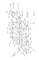
- FIG. 1A is a side cross sectional view along line A-A′ in FIG. 1B and FIG. 1B is a top view of a memory device according to an embodiment.
- FIG. 1C is perspective view
- FIG. 1D is a side cross sectional view
- FIG. 1E is a top view of a memory device according to another embodiment.
- FIGS. 2A and 2B are side cross sectional views along rear plane (A) and front plane (B), respectively, of FIG. 2D
- FIGS. 2C-2F are perspective views a memory device according to another embodiment.
- FIGS. 3A, 3D, 3E and 3F are perspective views, FIG. 3B is modified circuit schematic and FIG. 3C is a top view of a memory device according to another embodiment.
- FIGS. 4A-4S are side cross sectional views and FIGS. 4T, 4U, 4W and 4X are perspective views of steps in a method of making a memory device according to the embodiment of FIGS. 3A-3F .
- FIGS. 5A, 5C-5E, 5G-5H, 5J and 5L-5O are side cross sectional views and FIGS. 5B, 5F, 5I and 5K are top cross sectional views of steps in a method of making a memory device according to another embodiment.
- a memory device 100 of one embodiment includes plural (e.g., at least two, such as four) interdigitated word lines and a single select transistor controlling plural (e.g., at least two) local bit lines.
- the device 100 includes a memory cell region 102 containing a plurality of memory cells 104 located in the memory cell region 102 .
- the memory device includes two identical memory device modules (e.g., sections) 101 a and 101 b , arranged side by side.
- various embodiments may include more or fewer memory device modules 101 , e.g., 1, 10, 100, 1,000 or more, e.g., in the range of one to a trillion or any sub-range thereof.
- the memory device modules 101 may be arranged, e.g., in two dimensional planar array (e.g., a rectangular array), or in any other suitable regular, irregular, or random pattern.
- the memory device 100 also includes a first bit line interconnect 106 a and a second bit line interconnect 106 b in module 101 a .
- Module 101 b contains similar bit line interconnects.
- a first plurality of electrically conductive local bit lines 108 a extend in a substantially vertical direction into the memory cell region 102 (e.g., in the z-direction in FIG. 1A ).
- a substantially vertical direction includes the vertical direction (e.g., perpendicular to the top substrate surface) and directions within 20 degrees from the vertical direction.
- two local bit lines 108 a are provided per module 101 a , but in other embodiments more maybe be used, e.g., 3, 4, 5, 6, 7 8, 9, 10 or more such as in the range of 2-100 or any sub-range thereof.
- Each local bit line 108 a e.g., both lines 108 a
- a second plurality of electrically conductive local bit lines 108 b extend in the substantially vertical direction into the memory cell region 102 and are horizontally offset from the first plurality of electrically conductive local bit lines 108 a .
- two local bit lines 108 b are provided per module 101 b , but in other embodiments more maybe be used, e.g., 3, 4, 5, 6, 7 8, 9, 10 or more such as in the range of 2-100 or any sub-range thereof.
- Each local bit line 108 b in the second plurality of electrically conductive local bit lines is electrically connected to the second bit line interconnect 106 b .
- the first plurality of electrically conductive local bit lines 108 b extend substantially 180 degrees (e.g., 180 degrees or within 160-200 degrees) from the second plurality of electrically conductive local bit lines 108 b .
- the lines 108 a may extend from the interconnect 106 a upward
- the lines 108 b may extend from the interconnect 106 b downward.
- the first plurality of local bit 108 a and first bit line interconnect 106 a may be electrically insulated from the second plurality of local bit lines 108 b and second bit line interconnect 106 b .
- a first insulating layer 109 a e.g., an oxide or nitride layer, such as a horizontal silicon nitride etch stop layer
- a second insulating layer 109 b (e.g., an oxide or nitride layer such as a horizontal silicon nitride etch stop layer) prevents the second bit line interconnect 106 b from contacting the first plurality of local bit lines 108 a.
- a first select transistor 110 a is electrically connected to the first bit line interconnect 106 a , and is configured to select the first plurality of electrically conductive local bit lines 108 a .
- a second select transistor 110 b is electrically connected to the second bit line interconnect 106 b , and is configured to select the second plurality of electrically conductive local bit lines 108 b .
- the transistors 110 may be located below the memory cell region 102 .
- a plurality of word lines 112 extend in a substantially horizontal direction into the memory cell region 102 (the y-direction in FIG. 1B ).
- a substantially horizontal direction includes the horizontal direction (e.g., parallel to the top substrate surface) and directions within 20 degrees from the horizontal direction.
- four word lines 112 are provided, but in other embodiments more or fewer maybe be used, e.g., 2, 3, 4, 5, 6, 7 8, 9, 10 or more such as in the range of 2-100 or any sub-range thereof.
- each word line 112 may include one or more word line combs 114 .
- each of the plurality of word lines shown in FIG. 1B comprises a first word line comb 114 a , a second word line comb 114 b , a third word line comb 114 c and a forth word line comb 114 d .
- four word lines combs 114 are provided, but in other embodiments more or fewer maybe be used, e.g., 2, 3, 4, 5, 6, 7 8, 9, 10 or more such as in the range of 2-100 or any sub-range thereof.
- the location and direction of the comb 114 a by the dashed line 114 a in FIG. 1A and its electrical connection between the word line fingers 116 is shown by the black circles in the line 114 a .
- the diagonal direction of the comb which extends in both vertical and horizontal directions will be explained in more detail with respect to FIGS. 3A-3F below.
- Each word line comb 114 comprises a plurality of electrically conductive fingers 116 .
- the plurality of electrically conductive fingers 116 for each word line comb 114 electrically contact other electrically conductive fingers of the same word line comb 114 and are electrically insulated from the electrically conductive fingers of the other word line combs 114 .
- the electrically conductive fingers 116 of the word line comb 114 a are in electrical connection with each other, but insulated from word line combs 114 b - 114 d .
- the fingers 116 of the same comb 114 may be electrically connected to each other by a word line interconnect 113 , such as a sidewall bridge described below in reference to FIGSs. 3 A- 3 F.
- this is accomplished by providing vertically offset crossings for the word line combs 114 .
- word line comb 114 b crosses over or under word line comb 114 a in the region 115 .
- Detailed techniques for implementing crossovers of this type using the sidewall bridge are described in more detail below in reference to FIGS. 3A-3F .
- the fingers 116 of some of the word line 112 combs 114 extend in a first substantially horizontal direction (as shown, the y-direction) from a first interconnect region 120 a into a first side of the memory cell region 102 .
- the fingers 116 of the remaining word line combs 114 extend in a second substantially horizontal direction (the opposite of the y-direction as shown in FIG. 1B ) from a second interconnect region 120 b into a second side of the memory cell region 102 opposite to the first side of the memory cell region.
- the first substantially horizontal direction extends an angle of about 180 degrees (e.g., 160-200 degrees) with respect to the second horizontal direction.
- the fingers 116 of the word line combs are alternately interdigitated in the memory cell region 102 .
- each finger 116 is separated from an overlying and/or underlying finger by a respective insulating layer 117 .
- a row through the memory cell region 102 along a horizontal direction substantially perpendicular to the first and the second substantially horizontal directions comprises at least four fingers of the word line combs, at least four local bit lines, and at least eight memory cells arranged in a following order: a first finger 116 - 1 of the first word line comb 114 a , a first memory cell 104 a , a first local bit line 108 a 1 of the first plurality of electrically conductive local bit lines 108 a , a second memory cell 104 b , a first finger 116 - 3 of the third word line comb 114 c , a third memory cell 104 c , a first local bit line 108 b 1 of the second plurality of electrically conductive local bit lines 108 b , a fourth memory cell 104 d , a first finger 116 - 2 of the second word
- Each memory cell 104 is in contact with one finger 116 of one word line comb 114 and with one local bit line 108 , and so may be individually addressed.
- the memory cells 104 may be any type of memory cells know in the art including, e.g., transistor based memory sells (e.g., NAND cells) or variable resistivity state memory cells.
- the memory device 100 comprises a monolithic, three dimensional resistive random access (ReRAM) non-volatile memory device, where the plurality of memory cells 104 comprise a plurality of variable resistance elements that include a resistivity switching material 103 located at an intersection of and in contact with one finger 116 of one word line comb 114 and one local bit line 108 .
- ReRAM resistive random access
- the material 103 may be a material layer which extends along the sidewalls of the local bit lines 108 .
- the material 103 may comprise any suitable variable resistivity material that can have different electrical resistivity depending on the state, the phase, or the density of microscopic structures such as filaments, within the material.
- the variable resistivity material 103 is a read/write non-volatile memory (NVM) material selected from a chalcogenide and a metal oxide material, and exhibits a stable, reversible shift in resistance in response to an external voltage applied to the material or to a current passed through the material.
- NVM read/write non-volatile memory
- the material 103 may comprise a metal oxide, such as TiOx, HfOx, ZrOx, WOx, NiOx, CoOx, CoAlOx, MnOx, ZnMn 2 O 4 , ZnOx, TaOx, NbOx, HfSiOx, or HfAlOx, where “x” indicates either a stoichiometric metal oxide (e.g., HfO 2 ) or a non-stoichiometric metal oxide (e.g., HfO 2-y ).
- a metal oxide such as TiOx, HfOx, ZrOx, WOx, NiOx, CoOx, CoAlOx, MnOx, ZnMn 2 O 4 , ZnOx, TaOx, NbOx, HfSiOx, or HfAlOx, where “x” indicates either a stoichiometric metal oxide (e.g., HfO 2
- the bit line interconnects 106 may be on opposing sides of the memory cell region 102 .
- the first bit line interconnect 106 a is located below memory cell region 102 and the second bit line interconnect 106 b is located above the memory cell region.
- the first plurality of electrically conductive local bit lines 108 a extend into the memory cell region 102 from below and the second plurality of electrically conductive local bit lines 108 b extend into the memory cell region from above.
- the first bit line interconnect 106 a electrically connected to the first plurality of electrically conductive local bit lines 108 a comprises a first bit line comb 122 a .
- the second bit line interconnect 106 b electrically connected to the second plurality of electrically conductive local bit lines 108 b comprises a second bit line comb 122 b.
- the first and second bit line combs 122 a and 122 b may be arranged such that a local bit line 108 a in the first bit line comb 122 a is interdigitated between two electrically conductive local bit lines 108 b in the second bit line comb 122 b , and a local bit line 108 b in the second bit line comb 122 b is interdigitated between two electrically conductive local bit lines 108 a in the first bit line comb 122 a.
- the memory device 100 may include a plurality of global bit lines 150 , e.g., a first global bit line 150 a and a second global bit line 150 b .
- the device 100 may also include additional global bit lines 150 c , 150 d , etc.
- the first select transistor 110 a comprises a first vertical thin film transistor having an upper source or drain region 111 u of a first conductivity type located above a channel region 111 c of a second conductivity type, a lower drain or source region 111 d of the first conductivity type located below the channel region (e.g., in electrical contact with a global bit line 150 a ), and a first gate electrode 130 a located adjacent to the channel region 111 c.
- the second select transistor 110 b comprises a second vertical thin film transistor having an upper a source or drain region 111 u of the first conductivity type located above a channel region 111 c of the second conductivity type, a lower drain or source region 111 d of the first conductivity type located below the channel region (e.g., in electrical contact with a global bit line 150 b ), and a second gate electrode 130 b located adjacent to the channel region.
- the upper source or drain region 111 u of the first select transistor 110 a is electrically connected to the first bit line interconnect 106 a .
- the lower drain or source region 111 d of the first select transistor 110 a is electrically connected to the first global bit line 150 a which is located below the first select transistor 110 a.
- the upper source or drain region 111 u of the second select transistor 110 b is electrically connected to the second bit line interconnect 106 b , as shown in FIG. 1A .
- the lower drain or source region 111 d of the second select transistor 110 b is electrically connected to the second global bit line 150 b which is located below the second select transistor 110 b.
- the first and the second global bit lines 150 a and 150 b each comprise elongated electrically conductive lines extending in a direction substantially parallel to the fingers 116 of the word line combs 114 (e.g., the y-direction).
- the first and the second gate electrodes 130 a and 130 b comprise first and second portions of a first select gate line 131 a located adjacent to the respective first select transistor 110 a and second select transistor 110 b .
- the first select gate line 131 comprises an elongated electrically conductive line extending in a substantially horizontal direction (the x-direction in FIG. 1A ) substantially perpendicular to the first and the second global bit lines 150 a and 150 b and to the fingers 116 of the word lines combs 114 .
- additional select transistors 110 , select gate lines 131 , and global bit lines 150 may be provided.
- each TFT select transistor 110 is a shared gate transistor with relatively wide channel regions extending over two adjacent global bit lines 150 but electrically contacting only one of the two global bit lines 150 .
- Each select transistor 110 may have two gate electrodes 130 located on opposite side of the channel of the transistor.
- a gate insulating layer may be located between the channel and the gate electrode.
- 1C and 1D includes a third select transistor 110 c which comprises a third vertical thin film transistor, a fourth select transistor 110 d which comprises a fourth vertical thin film transistor, a third global bit line 150 c located between the first and the second global bit lines 150 a and 150 b , and a fourth global bit line 150 d located adjacent to the second global bit line 150 b .
- Some embodiments further include a second select gate line 131 b and a third select gate line 131 c.
- Some embodiments are arranged such that the first, the second, the third and the fourth global bit lines 150 a - 150 d extend substantially parallel to each other in a substantially horizontal direction (as shown the y-direction) below the memory cell region 102 .
- Optional respective electrodes 151 a - 151 d electrically connect the source or drain region 111 d of each transistor 110 to a respective global bit line 150 a - 150 d .
- the electrodes 151 may be omitted and the source or drain region 111 d of each transistor 110 may be located directly on the respective global bit line 150 a - 150 d , as shown in FIG. 1A .
- the first, the second and the third select gate lines 131 a , 131 b , and 131 c extend substantially parallel to each other in a substantially horizontal direction (as shown the x-direction) substantially perpendicular to the first, the second, the third and the fourth global bit lines 150 a - 150 d.
- the first select transistor 110 a is located above the first and the third global bit lines 150 a and 150 c , and between the first and the second select gate lines 131 a and 131 b .
- the second select transistor 110 b is located above the second and the fourth global bit lines 150 b and 150 d , and between the first and the second select gate lines 131 a and 131 b .
- the third select transistor 110 c is located above the first and the third global bit lines 150 a and 150 c and between the second and the third select gate lines 131 b and 131 c .
- the fourth select transistor is 110 a is located above the second and the fourth global bit lines 150 b and 150 d , and between the second and the third select gate lines 131 b and 131 c.
- each select transistor 110 may be used to select a respective bit line interconnect 106 and associated plurality of local bit lines 108 .
- the first select transistor 110 a may be selected by switching on the first and second gate lines 131 a and 131 b along with the first global bit line 150 a .
- the second select transistor 110 b may be selected by switching on the first and second gate lines 131 a and 131 b along with the second global bit line 150 b .
- the third select transistor 110 c may be selected by switching on the second and third gate lines 131 b and 131 c along with the third global bit line 150 c .
- the fourth select transistor 110 d may be selected by switching on the second and third gate lines 131 b and 131 c along with the fourth global bit line 150 d.
- the width of the first select transistor 110 a is about 3F in a direction (as shown the x-direction) substantially parallel to the first and second select gate lines, where F is a minimum feature size in a semiconductor process used to fabricate the memory device 100 .
- the width of the channel 111 c of the transistor 110 a may be about 3F.
- the period between a corresponding point in the first and the second transistors 110 a and 110 b is about 4F in a direction (as shown the x direction) substantially parallel to the first and the second select gate lines 131 a and 131 b .
- the period between a corresponding point in the first and the third transistors 110 a and 110 c is about 2F in a direction (as shown, the y-direction) substantially perpendicular to the first and the second select gate lines 131 a and 131 b .
- the area of a select transistor module (indicated with dashed lines) containing one of the transistors 110 is about 8F 2 .
- the area of a memory device module 101 (not shown) located over the select transistor module is about 4F 2 .
- the word line finger 116 spacing in the memory cell 102 region is about 1F.
- the shared gate line configuration allows for two memory device modules 101 per select transistor module, reducing the memory device module area by a factor of two relative to the select transistor module area.
- this scaling is advantageous because relatively wide channel thin film transistors may be used, mitigating or reducing potential imperfections or malfunctions (e.g., current leakage) related to using relatively thin channels (e.g., with a width of less than 3F) for the select transistors 110 .
- FIGS. 2A-D show views of an alternate embodiment of the memory device 200 which is different from the device 100 of FIGS. 1A, 1C and 1E .
- FIGS. 2A and 2B are vertical (i.e., side) cross sectional views along rear plane (A) and front plane (B), respectively, in the perspective view of FIG. 2D .
- FIG. 2D is a close up perspective view of a rear portion of FIG. 2C bounded by the planes (A) and (B) in FIG. 2C .
- the word lines and resistivity switching material components of the device 200 are omitted in the perspective view of FIGS. 2C and 2D .
- the device 200 of FIGS. 2A-2D differs from the device 100 shown in FIGS. 1A, 1C and 1E in several ways.
- the select transistors of the memory device may be planar transistors, e.g., formed at least partially in the upper portion of a substrate 220 , rather than vertical TFTs formed over the global bit lines.
- at least some of the electrodes connecting the select transistors and the bit line interconnects may extend in both vertical and horizontal directions.
- the first select transistor 210 a is planar transistor having a channel region 201 a made of a semiconductor material of a second conductivity type located in a horizontal plane between source region 203 a and drain region 205 a made of a semiconductor region of a first conductivity type.
- the source region may be located out of the plane of FIG. 2A and the drain regions may be located out of the plane of FIG. 2B .
- each is shown in both FIGS. 2A and 2B to illustrate the relationship between the source and the drain.
- a gate electrode 207 a for the first select transistor 210 a is located adjacent to the channel region 201 a , and is separated from the channel by a gate insulating layer (not shown for clarity).
- the transistor 210 a is a dual gate transistor containing two gates 207 a , 207 aa , two drain regions 205 a , 205 aa , and two channels 201 a , 201 aa on either side of the common source region 203 a .
- the second select transistor 210 b is planar transistor having a channel region 201 b made of a semiconductor material of the second conductivity type located in a horizontal plane between source region 203 b and drain region 205 b made of a semiconductor region of the first conductivity type.
- a gate electrode 207 b for the second select transistor 210 b is located adjacent to the channel region 201 b .
- the transistor 210 b is also dual gate transistor containing two gates 207 b , 207 bb , two drain regions 205 b , 205 bb , and two channels 201 b , 201 bb on either side of the common source region 203 b.
- the channel, source, and drain regions may be formed in an upper portion of the substrate 220 (e.g., proximal the major surface of the substrate), such as a silicon substrate.
- the source and drain regions may be formed using any suitable doping techniques, such as ion implantation.
- the substrate 220 may comprise a p-type doped silicon wafer such that the channel comprises a p-type silicon channel, while the source and drain regions comprise n-type doped regions, such as phosphorus or arsenic implanted regions.
- the adjacent transistors may be isolated from each other by any suitable isolation regions, such as shallow trench isolation (STI) regions 222 .
- STI shallow trench isolation
- the source region 203 a of the first select transistor 210 a is electrically connected to the source line 209 which extends in level M 1 (i.e., the first/lower metal level).
- the first (e.g., left side) drain region 205 a of the first select transistor 210 a is electrically connected to an upper bit line interconnect 106 bb located in level M 4 (i.e., the fourth/top metal level) in the front vertical plane (B) by the electrode 151 a which has a horizontal portion extending in level M 2 (i.e., the second/middle metal level) from the rear vertical plane (A) to the front vertical plane (B).
- the second (e.g., right side) drain region 205 aa of the first select transistor 210 a is electrically connected to a lower bit line interconnect 106 aa located in level M 3 (i.e., the third/upper metal level) in the front vertical plane (B) by the electrode 151 aa which has a horizontal portion extending in level M 2 (i.e., the second/middle metal level) from the rear vertical plane (A) to the front vertical plane (B).
- the first (e.g., left side) gate electrode 207 a of the first select transistor is connected to or comprises a portion of the global bit line 150 a which is located below level M 1 .
- the second (e.g., right side) gate electrode 207 aa of the first select transistor is connected to or comprises a portion of the global bit line 150 aa which is located below level M 1 .
- the source region 203 b of the second select transistor 210 b is electrically connected to the source line 209 which extends in level M 1 (i.e., the first/lower metal level).
- the first (e.g., left side) drain region 205 b of the second select transistor 210 b is electrically connected to another lower bit line interconnect 106 a located in level M 3 (i.e., the third/upper metal level) in the rear vertical plane (A) by the electrode 151 b which extends vertically through level M 2 (i.e., the second/middle metal level).
- the second (e.g., right side) drain region 205 bb of the second select transistor 210 b is electrically connected to another upper bit line interconnect 106 b located in level M 4 (i.e., the fourth/top metal level) the rear vertical plane (A) by the electrode 151 bb which extends vertically through level M 2 (i.e., the second/middle metal level).
- the first (e.g., left side) gate electrode 207 b is connected to or comprises a portion of a global bit line 150 b which is located below level M 1 .
- the second (e.g., right side) gate electrode 207 bb is connected to or comprises a portion of a global bit line 150 bb which is located below level M 1 .
- the electrodes 151 b , 151 bb extend vertically in the rear vertical plane (A).
- the electrodes 151 a , 151 aa start out vertically in the rear vertical plane (A), then extend horizontally in level M 2 from plane (A) to the front vertical plane (B) and then again extend vertically in plane (B).
- the gate electrode 207 a of the first select transistor comprises a portion of the global bit line 150 a .
- the global bit line 150 a extends in a first horizontal direction (e.g., y-direction) over the first planar select transistor 210 a and an imaginary straight line 224 signifying the charge carrier (e.g., electron) flow direction in the channel between the source 203 a and the drain 205 a of the first planar select transistor 210 a extends in a second horizontal direction at an angle with respect to the first horizontal direction, e.g., an angle in the range of 20 to 70 degrees, as shown in FIG. 2C .
- a similar imaginary line signifies the charge carrier flow direction between the source 203 a and drain 205 aa.
- the gate electrode 207 b of the second select transistor 210 b comprises a portion of the global bit line 150 b .
- the third global bit line extends in the first horizontal direction over the planar second select transistor 210 b and an imaginary straight line between the source 203 b and the drain 205 b of the second planar select transistor 210 b extends in a second horizontal direction at an angle with respect to the first horizontal direction, e.g., an angle in the range of 20 to 70 degrees, similar to line 224 for transistor 210 a.
- the source line 209 extends in a third horizontal direction (e.g., x-direction) which is substantially perpendicular to the first horizontal direction.
- the source line 209 may contain horizontally and/or vertically extending electrodes 219 which contact the source regions 203 a , 203 b.
- FIG. 2E illustrates the details of the four transistors 210 a , 210 b , 210 c and 210 d from FIG. 2C without illustrating the electrodes, interconnects and bit lines for clarity.
- each transistor 210 a - 210 d has a first channel region 201 aa , 201 b , 201 cc and 201 d of a second conductivity type (e.g., p-type) located in a horizontal plane between respective source region 203 a , 203 b , 203 c and 203 d and a first drain region 205 aa , 205 b , 205 cc , 205 d of a first conductivity type (e.g., n-type).
- a second conductivity type e.g., p-type
- Transistor 210 c is located adjacent to transistor 210 a in a first horizontal direction (e.g., the y-direction) in the horizontal plane.
- a first channel edge 261 a containing the source region 203 a of the transistor 210 a faces a second channel edge 262 c containing the source region 203 c of transistor 210 c .
- Transistor 210 b is located adjacent to transistor 210 a in a second horizontal direction (e.g., the x-direction) in the horizontal plane.
- a third channel edge 263 a containing the first drain region 205 aa of transistor 210 a faces a fourth channel edge 264 b containing the first drain region 205 b of transistor 210 b .
- the second horizontal direction (e.g., the direction) is substantially perpendicular to the first horizontal direction (e.g., the direction).
- Transistor 210 d is located adjacent to transistor 210 c in the second horizontal direction (e.g., the x-direction) in the horizontal plane.
- a third channel edge 263 c containing the first drain region 205 cc of transistor 210 c faces a fourth channel edge 264 d containing the first drain region 205 d of transistor 210 d .
- Transistor 210 d is also located adjacent to adjacent to transistor 210 b in the first horizontal direction (e.g., the y-direction) in the horizontal plane.
- a first channel edge 261 b containing the source region 203 b transistor 210 b faces a second channel edge 262 d containing the source region 203 d of transistor 210 d.
- the first channel edge 261 of each transistor is located opposite the second channel edge 262 the same transistor, while the third channel edge 263 of each transistor is located opposite the fourth channel edge 264 of the same transistor.
- in the source region of each transistor 203 is offset in both the first and the second directions (i.e., in both the y and the x directions) with respect to the first drain region 205 of the same transistor (e.g., along line 224 shown in FIG. 2C ).
- the common source line 209 extends in the second direction (e.g., the x-direction) between transistors 210 a and 210 c and between transistors 210 b and 210 d .
- the source line 209 is electrically connected to the source regions 203 a - 203 d of the respective transistors 210 a - 210 d , as shown in FIG. 2C .
- a first common gate electrode 150 aa extends in the first direction (e.g., the y-direction) over the channel regions 201 aa , 201 cc between respective source regions 203 a , 203 c and the first drain regions 205 aa , 205 cc of transistors 210 a , 210 c .
- a second common gate electrode 150 b extends in the first direction over the channel regions 201 b , 201 d between respective source regions 203 b , 203 d and first drain regions 205 b , 205 d of transistors 210 b , 210 d.
- the transistors 210 a - 210 d may be dual channel/dual gate transistors.
- a second drain region 205 a is located in a fourth channel edge 264 a of transistor 210 a
- a second drain region 205 c is located in a fourth channel edge 264 c of transistor 201 c
- a second drain region 205 bb is located in a third channel edge 263 b of transistor 210 b
- a second drain region 205 dd is located in a third channel edge 263 d of transistor 210 d .
- a third common gate electrode 150 a extends in the first direction (e.g., the y-direction) over the channel regions 201 a , 201 c between respective source regions 203 a , 203 c and second drain regions 205 a , 205 c of transistors 210 a , 210 c .
- a fourth common gate electrode 150 bb extends in the first direction over the channel regions 201 bb , 201 dd between respective source regions 203 b , 203 d and second drain regions 205 bb , 205 dd of transistors 210 b , 210 d .
- the first common gate 150 aa electrode is connected to or comprises a portion of the first global bit line
- the second common gate electrode 150 b is connected to or comprises a portion of the second global bit line
- the third common gate electrode 150 a is connected to or comprises a portion of the third global bit line
- the fourth common gate electrode 150 bb is connected to or comprises a portion of the fourth global bit line.
- FIG. 2F is a close up perspective view of a front portion of FIGS. 2C and 2E bounded by the planes (C) and (D) in FIGS. 2C and 2E .
- the first drain region 205 aa , 205 b , 205 cc , 205 d of the respective select transistors 210 a , 210 b , 210 c and 210 d is electrically connected to a respective first 106 aa , second 106 a , third 106 a 3 and fourth 106 a 4 lower bit line interconnects.
- the second drain region 205 a , 205 bb , 205 c , 205 dd of the respective select transistors 210 a , 210 b , 210 c and 210 d is electrically connected to a respective first 106 bb , second 106 b , third 106 b 3 and fourth 106 b 4 upper bit line interconnects.
- the third 106 a 3 and fourth 106 a 4 lower bit line interconnects are connected to the respective drain regions by respective electrodes 151 c 3 and 151 d 3 .
- the third 106 b 3 and fourth 106 b 4 upper bit line interconnects are connected to the respective drain regions by respective electrodes 151 c 4 and 151 d 4 , as shown in FIG. 2F .
- the first 106 aa , second 106 a , third 106 a 3 and fourth 106 a 4 lower bit line interconnects are located below memory cell region 102
- the first 106 bb , second 106 b , third 106 b 3 and fourth 106 b 4 upper bit line interconnects are located above the memory cell region 102 , as shown in FIGS. 2A-2B .
- a first plurality of electrically conductive local bit lines 108 a are located in the vertical plane (C). These bit lines extend into the memory cell region 102 from below and are electrically connected to the lower bit line interconnect 106 a 3 , as shown in FIG. 2F .
- a second plurality of electrically conductive local bit lines 108 a are located in the vertical plane (D). These bit lines extend into the memory cell region 102 from below and are electrically connected to the lower bit line interconnect 106 a 4 , as shown in FIG. 2F .
- a third plurality of electrically conductive local bit lines 108 a are located in the vertical plane (B). These bit lines extend into the memory cell region 102 from below and are electrically connected to the lower bit line interconnect 106 aa , as shown in FIGS. 2C and 2D .
- a fourth plurality of electrically conductive local bit lines 108 a are located in the vertical plane (A). These bit lines extend into the memory cell region 102 from below and are electrically connected to the lower bit line interconnect 106 a , as shown in FIG. 2C .
- a fifth plurality of electrically conductive local bit lines 108 b are interdigitated with the second plurality of electrically conductive local bit lines 108 a in the vertical plane (D). These bit lines 108 b extend into the memory cell region 102 from above and are electrically connected to the upper bit line interconnect 106 b 3 , as shown in FIG. 2F .
- a sixth plurality of electrically conductive local bit lines 108 b are interdigitated with the first plurality of electrically conductive local bit lines 108 a in the vertical plane (C). These bit lines 108 b extend into the memory cell region 102 from above and are electrically connected to the second upper bit line interconnect 106 b 4 , as shown in FIG. 2F .
- a seventh plurality of electrically conductive local bit lines 108 b are interdigitated with the third plurality of electrically conductive local bit lines 108 a in the vertical plane (B). These bit lines 108 b extend into the memory cell region 102 from above and are electrically connected to the upper bit line interconnect 106 bb .
- An eighth plurality of electrically conductive local bit lines 108 b are interdigitated with the fourth plurality of electrically conductive local bit lines 108 a in the vertical plane (A). These bit lines 108 b extend into the memory cell region 102 from above and are electrically connected to the upper bit line interconnect 106 b , as shown in FIGS. 2C-2D .
- FIGS. 3A-3F illustrate a word line 112 contact scheme for a memory device of the types described herein, such as the devices of FIGS. 1A-1E or FIGS. 2A-2F .
- FIGS. 3A-3F illustrate how the fingers 116 of the same comb 114 may be electrically connected to each other by a word line interconnect 113 , such as a sidewall bridge word line interconnect in region 115 which is shown in FIG. 1B .
- FIG. 3A is a schematic perspective view of the word line combs and word line interconnects
- FIGS. 3B and 3C are respective electrical schematic view and top view of the word line combs and word line interconnects shown in FIG. 3A .
- FIGS. 3D, 3E and 3F are close up perspective views of a portion the word line combs and word line interconnects of FIGS. 3A and 3C .
- each of the first 114 - 1 , second 114 - 2 , third 114 - 3 and fourth 114 - 4 word line combs may be positioned diagonally with respect to the horizontal direction (e.g., the x-direction), such that one side of the comb (e.g., the left or the right side) is located below the opposite side (e.g., the other one of the left or the right side in FIGS. 3B and 3F ) of the same comb.
- each comb extends in both the vertical direction (e.g., z-direction) and a first horizontal direction (e.g., the x-direction).
- the fingers 116 extend away from the interconnect 113 in the second horizontal direction (e.g., the y-direction) which is perpendicular to the first horizontal direction.
- FIG. 3F shows one part of a word line comb 114 containing four contact pads and four associated fingers.
- the word line comb 114 may corresponds to one of word line combs 114 a to 114 d in FIG. 1B or it may correspond to one of the word line combs 114 - 1 to 114 - 4 in FIGS. 3A-3C .
- the word line combs 114 a to 114 d in FIG. 1B may be the same as the respective word line combs 114 - 1 to 114 - 4 in FIGS. 3A-3C .
- each may extend in the same horizontal x-y plane and thus be different from the diagonal word line combs 114 - 1 to 114 - 4 in FIGS. 3A-3C which do not extend in the same horizontal plane and instead c as shown in FIGS. 3A, 3B and 3F .
- a four finger portion of one exemplary word line comb 114 of an embodiment of the present disclosure which may correspond to one of the combs 114 - 1 to 114 - 4 or to one of the combs 114 a to 114 d is shown in FIG. 3F .
- the comb 114 includes a first finger 116 a located in a first device level (i.e., in level “a” or L 1 ), a second finger 116 b located in a second device level (i.e., in level “b” or L 2 ) above the first device level, a third finger 116 c located in a third device level (i.e., in level “c” or L 3 ) above the second device level, and a fourth finger 116 d located in a fourth device level (i.e., in level “d” or L 4 ) above the third device level.
- the first, second, third and fourth fingers are offset from each other in a horizontal direction (e.g., the x-direction).
- a word line interconnect 113 (e.g., the sidewall bridge interconnect shown in FIGS. 3D and 3E ) electrically connects the first, second, third and fourth fingers at their respective contact pads 316 a , 316 b , 316 c and 316 d , which are located in respective device levels a-d (e.g., L 1 -L 4 ).
- each comb 114 is connected to a driver circuit (e.g., via global word line 350 ) by a single electrode 351 connected to the lowest contact pad 316 a .
- each word line comb is connected to a global word line 350 located below the memory cell region 102 by a respective electrode 351 .
- This means that outside electrical connection to the upper levels of the word lines is not required and all outside electrical connections to diagonally stacked word line combs can be formed on the bottom side of the combs 114 and below the second level (e.g., level “b”/L 2 ) of the memory cell region 102 .
- the first word line comb 114 - 1 includes a first finger 116 - 1 a located in the first device level, a second finger 116 - 1 b located in the second device level above the first device level, a third finger 116 - 1 c located in the third device level above the second device level, and a fourth finger 116 - 1 d located in the fourth device level above the third device level.
- the first, second, third and fourth fingers are offset from each other in a horizontal direction (e.g., the x-direction).
- the word line interconnect 113 - 1 electrically connects the first, second, third and fourth fingers.
- the word line interconnects 113 - 1 , 113 - 2 , 113 - 3 and 113 - 4 are located outside the memory cell region 102 in one of the interconnect regions 120 a or 120 b which are spaced from the memory cell region 102 in a perpendicular horizontal direction (e.g., the y-direction).
- the word line interconnect 113 - 1 of word line comb 114 - 1 shown in FIGS. 3A and 3B is located in interconnect region 120 a in area 3 A shown by the dashed lines in FIG. 3C .
- Interconnect 113 - 2 is also located in region 120 a .
- Interconnects 113 - 3 and 113 - 4 are located in interconnect region 120 b located on the opposite side of the memory cell region 102 from region 120 a.
- each word line finger 116 may include a contact pad 316 which is located in electrical contact with the respective finger 116 .
- the contact pad 316 is located in the same vertical device level as its respective finger 116 .
- each respective finger 116 - 1 , 116 - 2 , 116 - 3 and 116 - 4 contacts a respective contact pad 316 - 1 , 316 - 2 , 316 - 3 and 316 - 4 located in one of the interconnect regions 120 a or 120 b .
- the pads 316 are also located in the various vertical device levels.
- the first word line comb 114 - 1 includes the first finger 116 - 1 a which contacts pad 316 - 1 a located in the first device level, the second finger 116 - 1 b which contacts pad 316 - 1 b located in the second device level above the first device level, the third finger 116 - 1 c which contacts pad 316 - 1 c located in the third device level above the second device level, and the fourth finger 116 - 1 d which contacts pad 316 - 1 ad located in the fourth device level above the third device level, as shown in FIGS. 3A and 3B .
- each word line comb 114 includes fingers 116 , pads 316 and interconnect 113 which electrically connects the fingers 116 together into a single word line electrode by physically connecting the pads 316 of each finger 116 in the comb 114 .
- the first (lowest) device level contact pads 316 - 1 a , 316 - 2 a , 316 - 3 a and 316 - 4 a may have a bottom surface in contact with an optional respective word line electrode 350 - 1 , 350 - 2 , 350 - 3 and 350 - 4 .
- Each word line electrode 350 - 1 , 350 - 2 , 350 - 3 and 350 - 4 is electrically connected to a respective global word line 351 - 1 , 351 - 2 , 351 - 3 and 351 - 4 .
- the global word lines may extend in a horizontal direction (e.g., y-direction) below the memory cell region 102 , and either above, below or co-planar with the global bit lines 150 .
- FIGS. 3D and 3E are mirror image type views from the views of FIGS. 3A and 3B .
- region 3 D in FIG. 3A is a mirror image type close up of the interconnect shown in FIG. 3D .
- the word line interconnect 113 (e.g., interconnect 113 - 1 shown in region 3 D in FIG. 3A ) includes a first conductive vertical rail 12 a which extends in the first or the second horizontal direction (e.g., the horizontal y-direction or 180 degrees from the y-direction) and contacts a contact pad 316 - 1 aa of the first finger 116 - 1 aa in the first device level (e.g., in the lowest level “a” which corresponds to word line level “L 1 ”).
- the word line interconnect 113 also includes a second conductive vertical rail 12 b which extends in the same first or the second horizontal direction as the first rail (e.g., in the y-direction or 180 degrees from the y-direction) and contacts a contact pad 316 - 1 b of the second finger 116 - 1 b in the second device level.
- a first conductive sidewall bridge 12 c extends in a third horizontal direction (e.g., in the x-direction) substantially perpendicular to the first and the second horizontal directions. The conductive sidewall bridge 12 c contacts both the first 12 a and the second 12 b conductive vertical rails.
- the conductive sidewall bridge, the conductive vertical rails, the contact pads and the fingers may comprise any one or more c
- the interconnect pattern of two rails contacting the contact pads in adjacent device levels and a sidewall bridge connecting the two rails is then repeated for the remaining contact pads in the remaining device levels.
- a third conductive vertical rail 23 a extends in the first or the second horizontal direction and contacts another contact pad 316 - 1 bb of another second finger 116 - 1 bb in the second device level (e.g., device level “b” which corresponds to word line level “L 2 ”).
- the third conductive vertical rail 23 a contains two portions which are located on opposite sides of the first rail 12 a .
- the first rail 12 a extends to pad 316 - 1 aa through an opening the pads 316 - 1 bb and 316 - 1 cc , while the third rail 23 a portions extend only partially through the opening in pad 316 - 1 cc.
- a fourth conductive vertical rail 23 b extends in the first or the second horizontal direction and contacts a contact pad 316 - 1 c of the third finger 116 - 1 c in the third device level.
- the fourth conductive vertical rail 23 b contains two portions which are located on opposite sides of the second rail 12 b .
- the second rail 12 b extends to pad 316 - 1 b through an opening the pads 316 - 1 c and 316 - 1 d , while the fourth rail 23 b portions extend only partially through the opening in pad 316 - 1 d.
- a second conductive sidewall bridge 23 c extends in a third horizontal direction substantially perpendicular to the first and the second horizontal directions.
- the second bridge 23 c contains two portions which are located on opposite sides of the first bridge 12 c .
- the second bridge 23 c contacts both the third 23 a and the fourth 23 b conductive vertical rails.
- a fifth conductive vertical rail 34 a extends in the first or the second horizontal direction and contacts a contact pad 316 - 1 cc of the third finger 116 - 1 cc in the third device level (e.g., device level “c” which corresponds to word line level “L 3 ”).
- a sixth conductive vertical rail 34 b extends in the first or the second horizontal direction and contacts a contact pad 316 - 1 d of the fourth finger 316 - 1 d in the fourth device level (e.g., device level “d” which corresponds to word line level “L 4 ”).
- a third conductive sidewall bridge 34 c extends in a third horizontal direction substantially perpendicular to the first and the second horizontal directions, and contacts both the fifth 34 a and the sixth 34 b conductive vertical rails.
- the contact pads 316 - 1 aa , 316 - 1 bb and 316 - 1 cc are stacked above each other in stack 322 .
- the contact pads 316 - 1 a , 316 - 1 b , 316 - 1 c and 316 - 1 d are stacked above each other in stack 324 which is horizontally separated from stack 322 in the third horizontal direction (e.g., the x-direction).
- the fingers 116 - 2 a , 116 - 2 b , 116 - 2 c and 116 - 2 d of another word line comb 114 - 2 extend in the first or the second horizontal direction between the stacks 322 and 324 .
- the conductive sidewall bridges 12 c , 23 c and 34 c of the word line interconnect 113 - 1 of word line comb 114 - 1 extend over the fingers 116 - 2 a , 116 - 2 b , 116 - 2 c and 116 - 2 d of the word line comb 114 - 2 .
- the fingers 116 - 2 a , 116 - 2 b , 116 - 2 c and 116 - 2 d of word line comb 114 - 2 may be covered by an insulating layer 330 , such as a silicon nitride hard mask layer, which electrically isolates the upper finger 116 - 2 d from the conductive sidewall bridges 12 c , 23 c and 34 c of the word line interconnect 113 - 1 of word line comb 114 - 1 .
- an insulating layer 330 such as a silicon nitride hard mask layer
- the fingers 116 - 2 a , 116 - 2 b , 116 - 2 c and 116 - 2 d of word line comb 114 - 2 extend to a different word line interconnect 113 - 2 which is offset from the interconnect 113 - 1 in the first or the second horizontal directions in the interconnect region 120 a , as shown in FIG. 3A .
- the above pattern is repeated in the third horizontal direction (i.e., the x-direction), as shown in FIG. 3E .
- the contact pads 316 - 1 aa , 316 - 1 bb , 316 - 1 cc and 316 - dd in stack 322 extend in the first or the second horizontal directions (e.g., the y-direction or 180 degrees from the y-direction) past the sidewall bridges 12 c , 23 c and 34 c.
- a set vertical conductive rails 12 bb , 23 bb and 34 bb contacts rear (or front depending on the viewpoint) of the respective contact pads 316 - 1 bb , 316 - 1 cc and 316 - 1 dd in stack 322 .
- Another set of conductive rails 12 aa , 23 aa and 34 aa contacts rear (or front depending on the viewpoint) of the respective contact pads 316 - 1 a 3 , 316 - 1 b 3 and 316 - 1 c 3 in stack 326 .
- Another set of sidewall bridges 12 cc , 23 cc and 34 cc connects the respective set of rails 12 aa - 12 bb , 23 aa - 23 bb and 34 aa - 34 bb to each other.
- Fingers 116 - 2 aa , 116 - 2 bb , 116 - 2 cc and 116 - 2 dd of another word line comb 114 - 2 extend in the first or the second horizontal direction between the stacks 322 and 326 .
- the conductive sidewall bridges 12 cc , 23 cc and 34 cc of the word line interconnect 113 - 1 of word line comb 114 - 1 extend over the fingers 116 - 2 aa , 116 - 2 bb , 116 - 2 cc and 116 - 2 dd of the word line comb 114 - 2 .
- the above pattern is repeated for all interconnects in the third horizontal direction (i.e., the x-direction), as shown in FIGS. 3A-3C .
- each pair of finger 116 and pad 316 in a stack are separated from an overlying and/or underlying finger and pad pair by a respective insulating layer.
- the insulating layers 117 are not shown in FIGS. 3A-3F for clarity.
- the interconnect is described above as the word line interconnect 113 which includes the rails and the sidewall bridges for a three dimensional ReRAM device, it should be understood that the interconnect may be used for any other suitable device, such another memory device (e.g., a NAND memory device) or a non-memory device, such as a logic device. Furthermore, the interconnect does not have to connect word line portions, such as combs, and may be used to connect bit line portions or any other conductors.
- FIGS. 4A-4X illustrate a method of making an interconnect between electrodes in a three dimensional device.
- the method of making the interconnect will be described below as the method of making the word line interconnect 113 which includes the rails and the sidewall bridges for a three dimensional ReRAM device of FIGS. 3A-3F , it should be understood that the method may be used to make an interconnect for any other suitable device, such another memory device (e.g., a NAND memory device) or a non-memory device, such as a logic device. Furthermore, the interconnect does not have to connect word line portions and may be used to connect bit line portions or any other conductors.
- the method includes providing the first stack 324 of electrodes 316 comprising a first electrode (e.g., contact pad) 316 - la located in the first device level, a second electrode (e.g., contact pad) 316 - 1 b located in the second device level above the first device level, a third electrode (e.g., contact pad) 316 - 1 c located in the third device level above the second device level, and a fourth electrode (e.g., contact pad) 316 - 1 d located in a fourth device level above the third device level.
- a first electrode e.g., contact pad
- a second electrode e.g., contact pad
- 316 - 1 b located in the second device level above the first device level
- a third electrode e.g., contact pad
- a fourth electrode e.g., contact pad
- the method also includes providing the second stack 322 of electrodes 316 which is offset in a substantially horizontal direction (e.g., in the x-direction) from the first stack 324 of electrodes.
- the second stack 322 of electrodes comprises a first electrode (e.g., contact pad) 316 - 1 aa located in the first device level, a second electrode (e.g., contact pad) 316 - 1 bb located in the second device level above the first device level, a third electrode (e.g., contact pad) 316 - 1 cc located in the third device level above the second device level, and a fourth electrode (e.g., contact pad) 316 - 1 dd located in the fourth device level above the third device level.
- the method also includes forming an insulating fill layer 402 over the first 324 and the second 322 stacks of electrodes.
- a first opening 404 is formed to the fourth electrode 316 d in the first stack 324 of electrodes through the insulating fill layer 402 .
- the first opening 404 may be formed using any suitable patterning method, such as photolithography and etching through a first mask 406 .
- a second opening 408 is formed through the insulating fill layer 402 and through the fourth electrode 316 dd to the third electrode 316 cc in the second stack 322 of electrodes, as shown in FIG. 4C .
- the second opening 408 may be formed using any suitable patterning method, such as photolithography and etching through a second mask 410 .
- the center portion of the insulating fill layer 402 between the stacks 322 and 324 may then be removed to form a connecting opening 412 which connects the upper parts of the first 404 and the second 408 openings.
- the connecting opening 412 may be formed using any suitable patterning method, such as photolithography and etching through a third mask 414 .
- the etching may be selective to the insulating layer 402 (e.g., silicon oxide) and may stop on the silicon nitride etch stop layer 330 located over the word line fingers 116 - 2 , and on the exposed portions of the electrodes 316 - 1 d and 316 - 1 cc in the respective openings 404 and 408 .
- a first insulating layer 416 is formed in the first 404 and the second 408 openings.
- Any suitable insulating material may be used, such as silicon oxide, silicon nitride, etc.
- the first insulating layer 416 may be a silicon oxide isolation layer located on sidewalls of the first 404 and the second 408 openings.
- the first insulating layer 416 is located on sidewalls and bottoms of the first, the second and the connecting openings.
- the first insulating layer 416 may be etched using an anisotropic sidewall spacer anisotropic etch to remove layer 416 from the horizontal surfaces (e.g., from the bottoms of the first and the second openings) and to leave insulating sidewall spacers (i.e., spacer portions) 416 S on the sidewalls of the openings 404 and 408 .
- the fourth electrode 316 - 1 d is exposed in the bottom of the first opening 404 and the third electrode 316 - 1 cc is exposed in the bottom of the second opening 408 between the insulating sidewalls spacers 416 S.
- FIG. 4T is a perspective view of FIG. 4F .
- a first conductive layer 418 is conformally formed in the first 404 , the second 408 and the connecting 412 openings such that the first conductive layer 418 is located on the first insulating layer (e.g., over the insulating spacer 416 S portions of layer 416 ) over the sidewalls of the first, second and the connecting openings.
- the first conductive layer 418 may be any suitable conductive layer described above for forming the rails and bridges, such as tungsten, tungsten nitride, titanium, titanium nitride, aluminum, copper, their alloys, etc.
- the first conductive layer 418 electrically contacts and connects the fourth electrode 316 - 1 d exposed in the first opening 404 and the third electrode 316 - 1 cc exposed in the second opening 408 .
- the first conductive layer 418 may be etched using an anisotropic sidewall spacer anisotropic etch to remove layer 418 from the horizontal surfaces (i.e., from the bottoms of the first and the second openings) and to leave conductive sidewall spacers (e.g., spacer portions) 418 S on the sidewalls of the openings 404 , 408 and 412 .
- anisotropic sidewall spacer anisotropic etch to remove layer 418 from the horizontal surfaces (i.e., from the bottoms of the first and the second openings) and to leave conductive sidewall spacers (e.g., spacer portions) 418 S on the sidewalls of the openings 404 , 408 and 412 .
- Each spacer 418 S forms the fifth pillar 34 a portions in the second opening 408 in contact with the edge portions of the third electrode 316 - 1 cc , sixth pillar 34 b portions in the first opening 404 in contact with the edge portions of the fourth electrode 316 - 1 d , and third bridge portions 34 c in the connecting opening 412 (i.e., the spacers 418 S form an interconnection between word lines levels L 3 and L 4 shown in FIG. 3D ).
- FIG. 4U is a perspective view of FIG. 4H .
- the first opening 404 is extended by selective anisotropic etching through the fourth electrode 316 - 1 d and through the underlying interlayer insulating layer 117 to expose the third electrode 316 - c in the first electrode stack 324 without removing the first conductive layer 418 (i.e., the first conductive spacers 418 S) from over the sidewalls of the first opening 404 .
- the second opening 408 is also extended at the same time by the selective etching through the third electrode 316 - 1 cc to expose the second electrode 316 - 1 bb in the second electrode stack 322 without removing the first conductive layer 418 (i.e., the first conductive spacers 418 S) from over the sidewalls of the second opening 408 .
- FIG. 4W is a perspective view of FIG. 4I .
- a second insulating layer 426 (e.g., a silicon oxide layer) is formed in the first 404 and the second 408 openings such that the second insulating layer is located on sidewalls of the first, the second and the connecting openings (i.e., over the first conductive sidewall spacers 418 S).
- the second insulating layer 426 may be etched using a sidewall spacer anisotropic etch to remove layer 426 from the horizontal surfaces and to leave second insulating sidewall spacers 426 S on the sidewalls of the openings 404 , 408 and 412 (i.e., over the first conductive sidewall spacers 418 S).
- the third electrode 316 - 1 c is exposed in the bottom of the first opening 404 and the second electrode 316 - 1 bb is exposed in the bottom of the second opening 408 between the insulating sidewalls spacers 426 S.
- FIG. 4X is a perspective view of FIG. 4K .
- a second conductive layer 428 is formed in the first 404 and the second 408 openings.
- the second conductive layer 428 is located on the second insulating layer 426 (e.g., on the spacers 426 S) over the sidewalls of the first, the second and the connecting openings.
- the second conductive layer 428 electrically contacts and connects the third electrode 316 - 1 c exposed in the first opening 404 and the second electrode 316 - 1 bb exposed in the second opening 408 .
- the second conductive layer 428 may be etched using a sidewall spacer anisotropic etch to remove layer 428 from the horizontal surfaces and to leave conductive sidewall spacers 428 S on the sidewalls of the openings 404 , 408 and 412 .
- Each spacer 428 S forms the third pillar 23 a portions in the second opening 408 in contact with the edge portions of the second electrode 316 - 1 bb , fourth pillar 23 b portions in the first opening 404 in contact with the edge portions of the third electrode 316 - 1 c , and second bridge portions 23 c in the connecting opening 412 (i.e., the spacers 428 S form an interconnection between word lines levels L 2 and L 3 shown in FIG.
- the middle part of the third electrode 316 - 1 c is exposed in the bottom of the first opening 404 and the middle part second electrode 316 - 1 bb is exposed in the bottom of the second opening 408 between the conductive sidewalls spacers 428 S (i.e., the between the pillar 23 a , 23 b portions).
- the first opening 404 is extended by selective etching through the third electrode 316 - 1 c to expose the second electrode 316 - 1 b in the first electrode stack 324 without removing the second conductive layer 428 (e.g., the spacers 428 S) from over the sidewalls of the first opening.
- the second opening 408 is also extended during the same selective etch through the second electrode 316 - 1 bb to expose the first electrode 316 - aa in the second electrode stack 322 without removing the second conductive layer 428 (e.g., the spacers 428 S) from over the sidewalls of the second opening.
- a third insulating layer 436 is formed in the first 404 and the second 408 openings such that the third insulating layer is located on sidewalls of the first, the second and the connecting openings.
- the third insulating layer 436 may be etched using a sidewall spacer anisotropic etch to remove layer 436 from the horizontal surfaces and to leave third insulating sidewall spacers 436 S on the sidewalls of the openings 404 , 408 and 412 (i.e., over the second conductive sidewall spacers 428 S).
- the second electrode 316 - 1 b is exposed in the bottom of the first opening 404 and the first electrode 316 - 1 aa is exposed in the bottom of the second opening 408 between the insulating sidewalls spacers 436 S.
- a third conductive layer 438 is formed in the first 404 , the second 408 and the connecting 412 openings.
- the third conductive layer 438 is located on the third insulating layer 436 (e.g., the spacers 436 S) over the sidewalls of the first, the second and the connecting openings.
- the third conductive layer 438 electrically contacts and connects the second electrode 316 - 1 b exposed in the first opening 404 and the first electrode 316 - 1 aa exposed in the second opening 408 .
- the third conductive layer 438 may be etched back to remove layer 438 from the connecting opening 412 while leaving the layer 438 to fill the remaining volume of the first 404 and the second 408 opening.
- the remaining portions of layer 438 form the first pillar 12 a portions in the second opening 408 in contact with the middle portion of the first electrode 316 - 1 aa , second pillar 12 b portions in the first opening 404 in contact with the middle portion of the second electrode 316 - 1 b , and first bridge 12 c in the connecting opening 412 (i.e., layer 438 forms an interconnection between word lines levels L 1 and L 2 shown in FIG. 3D ).
- gap fill insulating layer 440 (e.g., silicon oxide) is formed over layer 438 to fill the connecting opening 412 .
- gap fill insulating layer may include a liner and a filler material located over the liner.
- the first, second, third and fourth electrodes in the first stack 324 comprise a first stack of word line fingers 116 and contact pads 316 .
- the first, second, third and fourth electrodes in the second stack 322 comprise a second stack of word line fingers 116 and contact pads 316 .
- the first 418 , second 428 and third 438 conductive layers comprise respective first, second and third word line interconnects which connect one word line finger in one level in the first stack with a word line finger in another level in the second stack of a three dimensional device, such as a monolithic, three dimensional resistive random access (ReRAM) non-volatile memory device.
- a three dimensional device such as a monolithic, three dimensional resistive random access (ReRAM) non-volatile memory device.
- ReRAM resistive random access
- FIGS. 5A-5O show steps in a method of making a contact to a semiconductor device according to another embodiment.
- the method of making the contacts will be described below as the method of making the contacts to the select TFTs 110 of a three dimensional ReRAM device of FIGS. 1C-1D , it should be understood that the method may be used to make contacts to any other suitable device, such another memory device (e.g., a NAND memory device) or a non-memory device, such as a logic device.
- a memory device e.g., a NAND memory device
- a non-memory device such as a logic device.
- an in-process memory device is provided in step 50 .
- the device includes the global bit lines 150 and the electrodes 151 separated by an insulating fill 500 .
- the lines 150 and electrodes 151 may comprise any suitable conductive material, such as tungsten, tungsten nitride, titanium, titanium nitride, aluminum, copper, their alloys, etc.
- the insulating fill 500 may comprise any suitable insulating material, such as silicon oxide.
- Step 50 includes forming a conductive layer 501 over a semiconductor containing stack 503 .
- the conductive layer 501 may be a metal (e.g., tungsten, etc.) layer formed over a stack 503 including a lower barrier layer (e.g., TiN, or WN) 503 a , a semiconductor layer (e.g., polysilicon layer) 503 b and an upper barrier layer (e.g., TiN or WN) 503 c .
- a lower barrier layer e.g., TiN, or WN
- a semiconductor layer e.g., polysilicon layer
- an upper barrier layer e.g., TiN or WN
- the metal layer 501 may be relatively thin in comparison to the semiconductor layer 503 .
- Some embodiments may include forming a mask layer 504 over the conductive layer 501 .
- the mask layer 504 may be a hard mask layer, such as a silicon nitride layer.
- FIG. 5B shows the top view of the device and FIG. 5A is a side (i.e., vertical) cross section along line a-a′ in FIG. 5B .
- step 51 includes forming a first mask pattern (e.g., in the mask layer 504 ) over the conductive layer 501 (e.g., using photolithographic techniques) that exposes selected portion of the conductive layer 501 .
- the first mask pattern 505 includes a first plurality of openings 505 a , such as line shaped openings extending in a first horizontal direction and a second plurality of line shaped openings extending in a second horizontal direction substantially parallel to the first, such that the exposed portions are an array of rectangular exposed regions on the conductive layer 501 .
- other geometries for the first mask pattern may be used (e.g., exposing circular rather than rectangular regions of the conductive layer 501 ).
- step 52 includes etching portions of the conductive layer 501 and the semiconductor containing stack 503 exposed in the first mask pattern 505 to form a plurality of pillars 507 .
- Each pillar comprises a lower semiconductor region 507 a (e.g., polysilicon pillar having top and bottom TiN barrier portions) and an upper conductive region 507 b .
- plurality of pillars 507 includes an array of rectangular pillars. However, it is to be understood that other pillar shapes may be used, e.g., circular pillars.
- step 53 includes forming an insulating fill layer 509 between the plurality of pillars 507 .
- the insulating fill layer may be made of any suitable electrically insulating material, e.g., silicon oxide.
- step 53 may further include planarizing the device (e.g., using an etch back or chemical mechanical polishing process) to form a planar surface that exposes the tops of the pillars 507 (which, in some embodiments will include a residual portion of the mask layer 504 ).
- Each region 507 b form the channel 211 of the TFT select gate transistor 210 shown in FIGS. 1C and 1D .
- FIG. 5F shows the top view of the device and FIG. 5E is a side (i.e., vertical) cross section along line a-a′ in FIG. 5F .
- step 54 includes forming a second mask pattern 511 having openings 511 a (e.g., using photolithographic techniques) over the plurality of pillars (e.g., in mask layer 504 , or in an additional mask layer deposited over the device) and the insulating fill layer 509 .
- the second mask pattern of 511 comprises a plurality of lines 511 b (shown in FIG.
- step 55 includes etching the second edge portions 512 b of the upper conductive regions 507 a of each pair of the plurality of pillars 507 to leave a plurality of upper contacts 514 comprising the first edge portions 512 a of the upper conductive regions 507 a .
- Each of the plurality of upper contacts 514 is located on the respective lower semiconductor region 507 b in each of the plurality of pillars 507 .
- each of the plurality of upper contacts 514 is narrower than the respective lower semiconductor region 507 b of the pillar 507 .
- the use of two offset mask patterns 505 and 511 to form the upper contacts 514 may be advantageous in that the resulting the upper contacts 514 may be narrower in at least one horizontal direction than the minimum line with for the pattern forming process (e.g., photolithographic process) used to for the mask patterns.
- FIG. 5I shows the top view of the device and FIG. 5H is a side (i.e., vertical) cross section along line a-a′ in FIG. 5I .
- step 56 includes covering the plurality of upper contacts 514 with an electrically insulating fill layer 516 (e.g., silicon oxide), and planarizing the fill layer to expose a horizontal surface 518 that includes portions of the upper contacts 514 . Additional device layers may then be formed on the surface that use the upper contacts 514 to establish electrical connections with lower device layers.
- an electrically insulating fill layer 516 e.g., silicon oxide
- the method described above may be used to form interconnects in monolithic, three dimensional resistive random access (ReRAM) non-volatile memory device, e.g., of the type described herein.
- ReRAM resistive random access
- each of the plurality of lower semiconductor regions 507 b comprises a channel of a vertical thin film select gate transistor 110 .
- Each select gate transistor further comprises a global bit line 150 located below the channel and a gate line 131 which is located adjacent to a side of the channel 111 c .
- Source and drain regions may also be formed in the channel during the stack 503 deposition.
- Each of the plurality of upper contacts 514 comprises a lower portion of one of a plurality of local bit line interconnects 106 a of the memory device.
- the memory device may have a select gate and bit line structure similar to that of the lower portion of the device 100 shown in FIGS. 1C-1D .
- the rest of the device 100 may be constructed by forming a plurality of upper potions of the local bit line interconnects over the respective lower portions of the local bit line interconnects 106 a , as shown in FIG. 5L , and forming a memory cell region 102 over the upper portions of the plurality of local bit line interconnects 106 a , as shown in FIG. 5M .
- Region 102 may include the word lines 112 separated by insulating layers 117 as shown in FIG. 1A-1C , as well as the word line interconnects 113 shown in FIGS. 3A-3F .
- a plurality of vertically extending openings 520 are formed through the memory cell region 102 (i.e., through the word lines 112 and layers 117 ), as shown in FIG. 5N .
- the resistivity switching material 103 layers and the plurality of local bit lines 108 a , 108 b are formed in the openings 520 such that the plurality of local bit lines extend vertically into the memory cell region 102 .
- the respective lines 108 a , 108 b are formed in contact with each of the plurality of local bit line interconnects 106 a , 106 b (which is formed on top of the memory cell region 102 ), as shown in FIG. 5O .
Landscapes
- Engineering & Computer Science (AREA)
- Manufacturing & Machinery (AREA)
- Semiconductor Memories (AREA)
Abstract
Description
Claims (30)
Priority Applications (3)
| Application Number | Priority Date | Filing Date | Title |
|---|---|---|---|
| US14/614,709 US9419058B1 (en) | 2015-02-05 | 2015-02-05 | Memory device with comb-shaped electrode having a plurality of electrode fingers and method of making thereof |
| PCT/US2015/062545 WO2016126307A1 (en) | 2015-02-05 | 2015-11-24 | Memory device with comb electrode and method of making thereof |
| EP15808055.6A EP3254312B1 (en) | 2015-02-05 | 2015-11-24 | Memory device with comb electrode and method of making thereof |
Applications Claiming Priority (1)
| Application Number | Priority Date | Filing Date | Title |
|---|---|---|---|
| US14/614,709 US9419058B1 (en) | 2015-02-05 | 2015-02-05 | Memory device with comb-shaped electrode having a plurality of electrode fingers and method of making thereof |
Publications (2)
| Publication Number | Publication Date |
|---|---|
| US20160233270A1 US20160233270A1 (en) | 2016-08-11 |
| US9419058B1 true US9419058B1 (en) | 2016-08-16 |
Family
ID=54844040
Family Applications (1)
| Application Number | Title | Priority Date | Filing Date |
|---|---|---|---|
| US14/614,709 Expired - Fee Related US9419058B1 (en) | 2015-02-05 | 2015-02-05 | Memory device with comb-shaped electrode having a plurality of electrode fingers and method of making thereof |
Country Status (3)
| Country | Link |
|---|---|
| US (1) | US9419058B1 (en) |
| EP (1) | EP3254312B1 (en) |
| WO (1) | WO2016126307A1 (en) |
Cited By (7)
| Publication number | Priority date | Publication date | Assignee | Title |
|---|---|---|---|---|
| US9805805B1 (en) | 2016-08-23 | 2017-10-31 | Sandisk Technologies Llc | Three-dimensional memory device with charge carrier injection wells for vertical channels and method of making and using thereof |
| US10224372B2 (en) | 2017-05-24 | 2019-03-05 | Sandisk Technologies Llc | Three-dimensional memory device with vertical bit lines and replacement word lines and method of making thereof |
| US20190296082A1 (en) * | 2018-03-23 | 2019-09-26 | Toshiba Memory Corporation | Memory device |
| US10553537B2 (en) | 2018-02-17 | 2020-02-04 | Sandisk Technologies Llc | Interconnects containing serpentine line structures for three-dimensional memory devices and methods of making the same |
| US10879260B2 (en) | 2019-02-28 | 2020-12-29 | Sandisk Technologies Llc | Bonded assembly of a support die and plural memory dies containing laterally shifted vertical interconnections and methods for making the same |
| US11963360B2 (en) | 2015-05-26 | 2024-04-16 | Semiconductor Energy Laboratory Co., Ltd. | Semiconductor device |
| US12317763B2 (en) | 2021-11-03 | 2025-05-27 | International Business Machines Corporation | Memory cell with comb-shaped electrodes |
Families Citing this family (10)
| Publication number | Priority date | Publication date | Assignee | Title |
|---|---|---|---|---|
| KR102461150B1 (en) * | 2015-09-18 | 2022-11-01 | 삼성전자주식회사 | Three dimensional semiconductor device |
| KR102519458B1 (en) * | 2016-11-01 | 2023-04-11 | 삼성전자주식회사 | Nonvolatile memory device and operating method thereof |
| US10825516B2 (en) | 2018-02-27 | 2020-11-03 | Nantero, Inc. | Resistive change element cells sharing selection devices |
| CN111276486B (en) | 2018-12-07 | 2021-03-12 | 长江存储科技有限责任公司 | Novel 3D NAND memory device and method of forming the same |
| US11670588B2 (en) * | 2019-01-09 | 2023-06-06 | Intel Corporation | Selectable vias for back end of line interconnects |
| US11295810B2 (en) | 2019-06-07 | 2022-04-05 | Nantero, Inc. | Combinational resistive change elements |
| CN112864127B (en) * | 2019-11-28 | 2024-03-08 | 扬智科技股份有限公司 | Integrated circuit wire interconnect structure |
| US12029049B2 (en) | 2020-12-16 | 2024-07-02 | Winbond Electronics Corp. | Memory structures and methods for forming the same |
| US11763857B2 (en) * | 2021-05-14 | 2023-09-19 | Taiwan Semiconductor Manufacturing Company, Ltd. | Memory device and method of forming the same |
| KR20230075014A (en) * | 2021-11-22 | 2023-05-31 | 삼성전자주식회사 | Nonvolatile memory devices and mehtods of operatig nonvoltaile memory devices |
Citations (56)
| Publication number | Priority date | Publication date | Assignee | Title |
|---|---|---|---|---|
| US5915167A (en) | 1997-04-04 | 1999-06-22 | Elm Technology Corporation | Three dimensional structure memory |
| WO2002015277A2 (en) | 2000-08-14 | 2002-02-21 | Matrix Semiconductor, Inc. | Dense arrays and charge storage devices, and methods for making same |
| US20030062574A1 (en) | 2001-10-03 | 2003-04-03 | In-Cha Hsieh | Double vertical channel thin film transistor for SRAM and process of making the same |
| US20040042298A1 (en) | 2002-08-20 | 2004-03-04 | Horii Hideki | Phase changeable memory devices having reduced cell areas |
| US7005350B2 (en) | 2002-12-31 | 2006-02-28 | Matrix Semiconductor, Inc. | Method for fabricating programmable memory array structures incorporating series-connected transistor strings |
| US7023739B2 (en) | 2003-12-05 | 2006-04-04 | Matrix Semiconductor, Inc. | NAND memory array incorporating multiple write pulse programming of individual memory cells and method for operation of same |
| US7177191B2 (en) | 2004-12-30 | 2007-02-13 | Sandisk 3D Llc | Integrated circuit including memory array incorporating multiple types of NAND string structures |
| US7221588B2 (en) | 2003-12-05 | 2007-05-22 | Sandisk 3D Llc | Memory array incorporating memory cells arranged in NAND strings |
| US7233522B2 (en) | 2002-12-31 | 2007-06-19 | Sandisk 3D Llc | NAND memory array incorporating capacitance boosting of channel regions in unselected memory cells and method for operation of same |
| US20070210338A1 (en) | 2006-03-08 | 2007-09-13 | Orlowski Marius K | Charge storage structure formation in transistor with vertical channel region |
| US20070252201A1 (en) | 2006-03-27 | 2007-11-01 | Masaru Kito | Nonvolatile semiconductor memory device and manufacturing method thereof |
| US20090001344A1 (en) | 2007-06-29 | 2009-01-01 | April Schricker | Memory cell that employs a selectively grown reversible resistance-switching element and methods of forming the same |
| US7514321B2 (en) | 2007-03-27 | 2009-04-07 | Sandisk 3D Llc | Method of making three dimensional NAND memory |
| US7575973B2 (en) | 2007-03-27 | 2009-08-18 | Sandisk 3D Llc | Method of making three dimensional NAND memory |
| US20090230449A1 (en) | 2008-03-17 | 2009-09-17 | Kabushiki Kaisha Toshiba | Semiconductor storage device |
| US20090230512A1 (en) | 2008-03-13 | 2009-09-17 | Samsung Electronics Co., Ltd. | Nonvolatile Memory Devices that Use Resistance Materials and Internal Electrodes, and Related Methods and Processing Systems |
| US20100013049A1 (en) | 2008-07-18 | 2010-01-21 | Kabushiki Kaisha Toshiba | Semiconductor memory device and method for manufacturing same |
| US20100044778A1 (en) | 2008-08-21 | 2010-02-25 | Kwang-Soo Seol | Non-volatile memory device and method of manufacturing same |
| US20100112769A1 (en) | 2007-11-08 | 2010-05-06 | Samsung Electronics Co., Ltd. | Vertical-type non-volatile memory devices and methods of manufacturing the same |
| US20100120214A1 (en) | 2008-11-12 | 2010-05-13 | Samsung Electronics Co., Ltd. | Method of manufacturing nonvolatile memory device and nonvolatile memory device manufactured by the method |
| US20100155818A1 (en) | 2008-12-24 | 2010-06-24 | Heung-Jae Cho | Vertical channel type nonvolatile memory device and method for fabricating the same |
| US20100155810A1 (en) | 2008-12-24 | 2010-06-24 | Samsung Electronics Co., Ltd. | Multi-layer nonvolatile memory devices having vertical charge storage regions |
| US7745265B2 (en) | 2007-03-27 | 2010-06-29 | Sandisk 3D, Llc | Method of making three dimensional NAND memory |
| US20100181610A1 (en) | 2009-01-19 | 2010-07-22 | Samsung Electronics Co., Ltd. | Non-volatile memory device and method for fabricating non-volatile memory device |
| US20100207195A1 (en) | 2007-12-11 | 2010-08-19 | Kabushiki Kaisha Toshiba | Non-volatile semiconductor storage device and method of manufacturing the same |
| US7808038B2 (en) | 2007-03-27 | 2010-10-05 | Sandisk 3D Llc | Method of making three dimensional NAND memory |
| US20100254191A1 (en) | 2009-04-01 | 2010-10-07 | Byoungkeun Son | Semiconductor memory device comprising three-dimensional memory cell array |
| KR20100109745A (en) | 2009-04-01 | 2010-10-11 | 삼성전자주식회사 | Semiconductor device and method of forming the same |
| US7846782B2 (en) | 2007-09-28 | 2010-12-07 | Sandisk 3D Llc | Diode array and method of making thereof |
| US7848145B2 (en) | 2007-03-27 | 2010-12-07 | Sandisk 3D Llc | Three dimensional NAND memory |
| US7851851B2 (en) | 2007-03-27 | 2010-12-14 | Sandisk 3D Llc | Three dimensional NAND memory |
| US20100320528A1 (en) | 2009-06-22 | 2010-12-23 | Samsung Electronics Co., Ltd. | Three-dimensional semiconductor memory device |
| US20110031546A1 (en) | 2009-08-06 | 2011-02-10 | Kabushiki Kaisha Toshiba | Method for manufacturing semiconductor device and apparatus for manufacturing same |
| KR20110021444A (en) | 2009-08-26 | 2011-03-04 | 삼성전자주식회사 | 3D semiconductor memory device and manufacturing method thereof |
| US20110076819A1 (en) | 2009-09-29 | 2011-03-31 | Jinho Kim | Three-dimensional semiconductor memory device and method of fabricating the same |
| US20110121403A1 (en) | 2008-10-09 | 2011-05-26 | Seung-Jun Lee | Semiconductor device and method of fabricating the same |
| US20110133606A1 (en) | 2008-08-01 | 2011-06-09 | Nikko Company | Apparatus for holding piezoelectric vibrator |
| US20110151667A1 (en) | 2009-12-18 | 2011-06-23 | Sung-Min Hwang | Methods of Manufacturing Three-Dimensional Semiconductor Devices and Related Devices |
| US20110169071A1 (en) | 2010-01-08 | 2011-07-14 | Kabushiki Kaisha Toshiba | Nonvolatile semiconductor memory device and method of manufacturing same |
| US8008710B2 (en) | 2008-08-12 | 2011-08-30 | Kabushiki Kaisha Toshiba | Non-volatile semiconductor storage device |
| US8053829B2 (en) | 2008-12-10 | 2011-11-08 | Samsung Electronics Co., Ltd. | Methods of fabricating nonvolatile memory devices |
| US20120001249A1 (en) | 2010-06-30 | 2012-01-05 | Sandisk Corporation | Ultrahigh density vertical nand memory device & method of making thereof |
| US20120001250A1 (en) | 2010-06-30 | 2012-01-05 | Sandisk Corporation | Ultrahigh density vertical nand memory device and method of making thereof |
| US20120001247A1 (en) | 2010-06-30 | 2012-01-05 | Sandisk Corporation | Ultrahigh density vertical nand memory device and method of making thereof |
| US8187932B2 (en) | 2010-10-15 | 2012-05-29 | Sandisk 3D Llc | Three dimensional horizontal diode non-volatile memory array and method of making thereof |
| US20120147648A1 (en) | 2010-12-14 | 2012-06-14 | Scheuerlein Roy E | Three dimensional non-volatile storage with dual gate selection of vertical bit lines |
| US8427859B2 (en) | 2010-04-22 | 2013-04-23 | Micron Technology, Inc. | Arrays of vertically stacked tiers of non-volatile cross point memory cells, methods of forming arrays of vertically stacked tiers of non-volatile cross point memory cells, and methods of reading a data value stored by an array of vertically stacked tiers of non-volatile cross point memory cells |
| US20130210211A1 (en) | 2011-08-15 | 2013-08-15 | Lidia Vereen | Vertical Cross-Point Memory Arrays |
| US8520425B2 (en) | 2010-06-18 | 2013-08-27 | Sandisk 3D Llc | Resistive random access memory with low current operation |
| US20130264631A1 (en) | 2012-04-10 | 2013-10-10 | SanDisk Technologies, Inc. | Vertical nand device with low capacitance and silicided word lines |
| US20130308363A1 (en) | 2012-05-15 | 2013-11-21 | Sandisk 3D Llc | Three dimensional non-volatile storage with interleaved vertical select devices above and below vertical bit lines |
| US20130313627A1 (en) | 2012-05-23 | 2013-11-28 | SanDisk Technologies, Inc. | Multi-Level Contact to a 3D Memory Array and Method of Making |
| US20130336037A1 (en) | 2012-06-15 | 2013-12-19 | Sandisk 3D Llc | 3d memory having vertical switches with surround gates and method thereof |
| KR20140008704A (en) | 2012-07-11 | 2014-01-22 | 삼성전자주식회사 | Semiconductor device and method of forming the same |
| US20150263069A1 (en) * | 2014-03-11 | 2015-09-17 | Crossbar, Inc. | Selector device for two-terminal memory |
| US20150294977A1 (en) * | 2014-04-14 | 2015-10-15 | Sang-Lok Kim | Nonvolatile memory device |
-
2015
- 2015-02-05 US US14/614,709 patent/US9419058B1/en not_active Expired - Fee Related
- 2015-11-24 EP EP15808055.6A patent/EP3254312B1/en not_active Not-in-force
- 2015-11-24 WO PCT/US2015/062545 patent/WO2016126307A1/en not_active Ceased
Patent Citations (59)
| Publication number | Priority date | Publication date | Assignee | Title |
|---|---|---|---|---|
| US5915167A (en) | 1997-04-04 | 1999-06-22 | Elm Technology Corporation | Three dimensional structure memory |
| WO2002015277A2 (en) | 2000-08-14 | 2002-02-21 | Matrix Semiconductor, Inc. | Dense arrays and charge storage devices, and methods for making same |
| US20030062574A1 (en) | 2001-10-03 | 2003-04-03 | In-Cha Hsieh | Double vertical channel thin film transistor for SRAM and process of making the same |
| US20040042298A1 (en) | 2002-08-20 | 2004-03-04 | Horii Hideki | Phase changeable memory devices having reduced cell areas |
| US7233522B2 (en) | 2002-12-31 | 2007-06-19 | Sandisk 3D Llc | NAND memory array incorporating capacitance boosting of channel regions in unselected memory cells and method for operation of same |
| US7005350B2 (en) | 2002-12-31 | 2006-02-28 | Matrix Semiconductor, Inc. | Method for fabricating programmable memory array structures incorporating series-connected transistor strings |
| US7023739B2 (en) | 2003-12-05 | 2006-04-04 | Matrix Semiconductor, Inc. | NAND memory array incorporating multiple write pulse programming of individual memory cells and method for operation of same |
| US7221588B2 (en) | 2003-12-05 | 2007-05-22 | Sandisk 3D Llc | Memory array incorporating memory cells arranged in NAND strings |
| US7177191B2 (en) | 2004-12-30 | 2007-02-13 | Sandisk 3D Llc | Integrated circuit including memory array incorporating multiple types of NAND string structures |
| US20070210338A1 (en) | 2006-03-08 | 2007-09-13 | Orlowski Marius K | Charge storage structure formation in transistor with vertical channel region |
| US20070252201A1 (en) | 2006-03-27 | 2007-11-01 | Masaru Kito | Nonvolatile semiconductor memory device and manufacturing method thereof |
| US7575973B2 (en) | 2007-03-27 | 2009-08-18 | Sandisk 3D Llc | Method of making three dimensional NAND memory |
| US7514321B2 (en) | 2007-03-27 | 2009-04-07 | Sandisk 3D Llc | Method of making three dimensional NAND memory |
| US7851851B2 (en) | 2007-03-27 | 2010-12-14 | Sandisk 3D Llc | Three dimensional NAND memory |
| US7745265B2 (en) | 2007-03-27 | 2010-06-29 | Sandisk 3D, Llc | Method of making three dimensional NAND memory |
| US7848145B2 (en) | 2007-03-27 | 2010-12-07 | Sandisk 3D Llc | Three dimensional NAND memory |
| US7808038B2 (en) | 2007-03-27 | 2010-10-05 | Sandisk 3D Llc | Method of making three dimensional NAND memory |
| US20090001344A1 (en) | 2007-06-29 | 2009-01-01 | April Schricker | Memory cell that employs a selectively grown reversible resistance-switching element and methods of forming the same |
| US7846782B2 (en) | 2007-09-28 | 2010-12-07 | Sandisk 3D Llc | Diode array and method of making thereof |
| US20100112769A1 (en) | 2007-11-08 | 2010-05-06 | Samsung Electronics Co., Ltd. | Vertical-type non-volatile memory devices and methods of manufacturing the same |
| US20100207195A1 (en) | 2007-12-11 | 2010-08-19 | Kabushiki Kaisha Toshiba | Non-volatile semiconductor storage device and method of manufacturing the same |
| US20090230512A1 (en) | 2008-03-13 | 2009-09-17 | Samsung Electronics Co., Ltd. | Nonvolatile Memory Devices that Use Resistance Materials and Internal Electrodes, and Related Methods and Processing Systems |
| US20090230449A1 (en) | 2008-03-17 | 2009-09-17 | Kabushiki Kaisha Toshiba | Semiconductor storage device |
| US20100013049A1 (en) | 2008-07-18 | 2010-01-21 | Kabushiki Kaisha Toshiba | Semiconductor memory device and method for manufacturing same |
| US20110133606A1 (en) | 2008-08-01 | 2011-06-09 | Nikko Company | Apparatus for holding piezoelectric vibrator |
| US8008710B2 (en) | 2008-08-12 | 2011-08-30 | Kabushiki Kaisha Toshiba | Non-volatile semiconductor storage device |
| US20100044778A1 (en) | 2008-08-21 | 2010-02-25 | Kwang-Soo Seol | Non-volatile memory device and method of manufacturing same |
| US20110121403A1 (en) | 2008-10-09 | 2011-05-26 | Seung-Jun Lee | Semiconductor device and method of fabricating the same |
| US20100120214A1 (en) | 2008-11-12 | 2010-05-13 | Samsung Electronics Co., Ltd. | Method of manufacturing nonvolatile memory device and nonvolatile memory device manufactured by the method |
| US20110266606A1 (en) | 2008-11-12 | 2011-11-03 | Samsung Electronics Co., Ltd. | Method of manufacturing nonvolatile memory device and nonvolatile memory device manufactured by the method |
| US8053829B2 (en) | 2008-12-10 | 2011-11-08 | Samsung Electronics Co., Ltd. | Methods of fabricating nonvolatile memory devices |
| US20100155810A1 (en) | 2008-12-24 | 2010-06-24 | Samsung Electronics Co., Ltd. | Multi-layer nonvolatile memory devices having vertical charge storage regions |
| US20100155818A1 (en) | 2008-12-24 | 2010-06-24 | Heung-Jae Cho | Vertical channel type nonvolatile memory device and method for fabricating the same |
| US20100181610A1 (en) | 2009-01-19 | 2010-07-22 | Samsung Electronics Co., Ltd. | Non-volatile memory device and method for fabricating non-volatile memory device |
| KR20100109745A (en) | 2009-04-01 | 2010-10-11 | 삼성전자주식회사 | Semiconductor device and method of forming the same |
| US20100254191A1 (en) | 2009-04-01 | 2010-10-07 | Byoungkeun Son | Semiconductor memory device comprising three-dimensional memory cell array |
| US20100320528A1 (en) | 2009-06-22 | 2010-12-23 | Samsung Electronics Co., Ltd. | Three-dimensional semiconductor memory device |
| US20110031546A1 (en) | 2009-08-06 | 2011-02-10 | Kabushiki Kaisha Toshiba | Method for manufacturing semiconductor device and apparatus for manufacturing same |
| KR20110021444A (en) | 2009-08-26 | 2011-03-04 | 삼성전자주식회사 | 3D semiconductor memory device and manufacturing method thereof |
| US20110076819A1 (en) | 2009-09-29 | 2011-03-31 | Jinho Kim | Three-dimensional semiconductor memory device and method of fabricating the same |
| US8394716B2 (en) | 2009-12-18 | 2013-03-12 | Samsung Electronics Co., Ltd. | Methods of manufacturing three-dimensional semiconductor devices and related devices |
| US20110151667A1 (en) | 2009-12-18 | 2011-06-23 | Sung-Min Hwang | Methods of Manufacturing Three-Dimensional Semiconductor Devices and Related Devices |
| US20110169071A1 (en) | 2010-01-08 | 2011-07-14 | Kabushiki Kaisha Toshiba | Nonvolatile semiconductor memory device and method of manufacturing same |
| US8427859B2 (en) | 2010-04-22 | 2013-04-23 | Micron Technology, Inc. | Arrays of vertically stacked tiers of non-volatile cross point memory cells, methods of forming arrays of vertically stacked tiers of non-volatile cross point memory cells, and methods of reading a data value stored by an array of vertically stacked tiers of non-volatile cross point memory cells |
| US8520425B2 (en) | 2010-06-18 | 2013-08-27 | Sandisk 3D Llc | Resistive random access memory with low current operation |
| US20120001249A1 (en) | 2010-06-30 | 2012-01-05 | Sandisk Corporation | Ultrahigh density vertical nand memory device & method of making thereof |
| US20120001247A1 (en) | 2010-06-30 | 2012-01-05 | Sandisk Corporation | Ultrahigh density vertical nand memory device and method of making thereof |
| US20120001250A1 (en) | 2010-06-30 | 2012-01-05 | Sandisk Corporation | Ultrahigh density vertical nand memory device and method of making thereof |
| US8187932B2 (en) | 2010-10-15 | 2012-05-29 | Sandisk 3D Llc | Three dimensional horizontal diode non-volatile memory array and method of making thereof |
| US8619453B2 (en) * | 2010-12-14 | 2013-12-31 | Sandisk 3D Llc | Three dimensional non-volatile storage with dual gate selection of vertical bit lines |
| US20120147648A1 (en) | 2010-12-14 | 2012-06-14 | Scheuerlein Roy E | Three dimensional non-volatile storage with dual gate selection of vertical bit lines |
| US20130210211A1 (en) | 2011-08-15 | 2013-08-15 | Lidia Vereen | Vertical Cross-Point Memory Arrays |
| US20130264631A1 (en) | 2012-04-10 | 2013-10-10 | SanDisk Technologies, Inc. | Vertical nand device with low capacitance and silicided word lines |
| US20130308363A1 (en) | 2012-05-15 | 2013-11-21 | Sandisk 3D Llc | Three dimensional non-volatile storage with interleaved vertical select devices above and below vertical bit lines |
| US20130313627A1 (en) | 2012-05-23 | 2013-11-28 | SanDisk Technologies, Inc. | Multi-Level Contact to a 3D Memory Array and Method of Making |
| US20130336037A1 (en) | 2012-06-15 | 2013-12-19 | Sandisk 3D Llc | 3d memory having vertical switches with surround gates and method thereof |
| KR20140008704A (en) | 2012-07-11 | 2014-01-22 | 삼성전자주식회사 | Semiconductor device and method of forming the same |
| US20150263069A1 (en) * | 2014-03-11 | 2015-09-17 | Crossbar, Inc. | Selector device for two-terminal memory |
| US20150294977A1 (en) * | 2014-04-14 | 2015-10-15 | Sang-Lok Kim | Nonvolatile memory device |
Non-Patent Citations (15)
| Title |
|---|
| Endoh, T.et al., titled "Novel Ultra High Density Memory With a Stacked-Surrounding Gate Transistor (S-SGT) Structured Cell", IEDM Proc. (2001) 33-36. |
| International Search Report & Written Opinion, PCT/US2011/042566, Jan. 17, 2012 (30 pp.). |
| International Search Report and Written Opinion of the International Searching Authority for PCT/US2015/062545, fated Feb. 23, 2016, 21 pages. |
| Invitation to Pay Additional Fees & Partial International Search Report, PCT/US2011/042566, Sep. 28, 2011. (7 pp.). |
| Invitation to Pay Additional Search Fees issued in PCT Application No. PCT/US13/41410, mailed Sep. 9, 2013.(6 pp.). |
| Jang et al., "Vertical Cell Array Using TCAT (Terabit Cell Array Transistor) Technology for Ultra High Density NAND Flash Memory," 2009 Symposium on VLSI Technology Digest of Technical Papers, pp. 192-193. |
| Katsumata et al., "Pipe-Shaped BiCS Flash Memory with 16 Stacked Layers and Multi-Level- Cell Operation for Ultra High Density Storage Devices," 2009 Symposium on VLSI Technology Digest of Technical Papers, pp. 136-137. |
| Kimura, Masahide "3D Cells Make Terabit NAND Flash Possible," Nikkei Electronics Asia, Sep. 17, 2009, 6pgs. |
| Maeda et al., "Multi-Stacked IG Cell/Layer Pipe-Shaped BiCS Flash Memory," 2009 Symposium on VLSI Technology Digest of Technical Papers, pp. 22-23. |
| Tanaka et al., "Bit-Cost Scalable Technology for Low-Cost and Ultrahigh-Density Flash Memory," Toshiba Review, vol. 63, No. 2, 2008, pp. 28-31. |
| U.S. Appl. No. 14/136,103, filed Dec. 20, 2013, Takaki. |
| U.S. Appl. No. 14/150,162, filed Jan. 8, 2014, Takaki et al. |
| U.S. Appl. No. 14/206,196, filed Mar. 12, 2014, Takaki. |
| U.S. Appl. No. 14/224,290, filed Mar. 25, 2014, Takaki. |
| U.S. Appl. No. 14/643,211, filed Mar. 10, 2015, Tobitsuka. |
Cited By (7)
| Publication number | Priority date | Publication date | Assignee | Title |
|---|---|---|---|---|
| US11963360B2 (en) | 2015-05-26 | 2024-04-16 | Semiconductor Energy Laboratory Co., Ltd. | Semiconductor device |
| US9805805B1 (en) | 2016-08-23 | 2017-10-31 | Sandisk Technologies Llc | Three-dimensional memory device with charge carrier injection wells for vertical channels and method of making and using thereof |
| US10224372B2 (en) | 2017-05-24 | 2019-03-05 | Sandisk Technologies Llc | Three-dimensional memory device with vertical bit lines and replacement word lines and method of making thereof |
| US10553537B2 (en) | 2018-02-17 | 2020-02-04 | Sandisk Technologies Llc | Interconnects containing serpentine line structures for three-dimensional memory devices and methods of making the same |
| US20190296082A1 (en) * | 2018-03-23 | 2019-09-26 | Toshiba Memory Corporation | Memory device |
| US10879260B2 (en) | 2019-02-28 | 2020-12-29 | Sandisk Technologies Llc | Bonded assembly of a support die and plural memory dies containing laterally shifted vertical interconnections and methods for making the same |
| US12317763B2 (en) | 2021-11-03 | 2025-05-27 | International Business Machines Corporation | Memory cell with comb-shaped electrodes |
Also Published As
| Publication number | Publication date |
|---|---|
| EP3254312B1 (en) | 2018-10-31 |
| EP3254312A1 (en) | 2017-12-13 |
| WO2016126307A1 (en) | 2016-08-11 |
| US20160233270A1 (en) | 2016-08-11 |
Similar Documents
| Publication | Publication Date | Title |
|---|---|---|
| US9419058B1 (en) | Memory device with comb-shaped electrode having a plurality of electrode fingers and method of making thereof | |
| US9450023B1 (en) | Vertical bit line non-volatile memory with recessed word lines | |
| TWI768783B (en) | Array of capacitors, array of memory cells, methods of forming an array of capacitors, and methods of forming an array of memory cells | |
| US9853090B2 (en) | Vertical bit line non-volatile memory systems and methods of fabrication | |
| CN107093612B (en) | Variable resistance memory device and method of manufacturing the same | |
| US9343507B2 (en) | Dual channel vertical field effect transistor including an embedded electrode | |
| US9818798B2 (en) | Vertical thin film transistors in non-volatile storage systems | |
| US9443910B1 (en) | Silicided bit line for reversible-resistivity memory | |
| TWI489592B (en) | Integrated circuit 3d memory array and manufacturing method | |
| JP5512700B2 (en) | Semiconductor memory device and manufacturing method thereof | |
| US8921180B2 (en) | High-integration semiconductor memory device and method of manufacturing the same | |
| US8933427B2 (en) | Variable resistance memory device and method for fabricating the same | |
| CN113196490A (en) | Three-dimensional NAND memory device including dual-terminal selector and methods of using and fabricating the same | |
| KR20170008198A (en) | Transistor device with gate bottom isolation and method of making thereof | |
| US10333065B2 (en) | Resistive memory device | |
| US8791443B2 (en) | High density variable resistive memory and method of fabricating the same | |
| US9577188B2 (en) | Semiconductor constructions and methods of forming memory cells | |
| CN113644087A (en) | Phase change memory and manufacturing method thereof | |
| US12527009B2 (en) | Memory device and method for operating the same | |
| KR20250019505A (en) | Semiconductor memory devices |
Legal Events
| Date | Code | Title | Description |
|---|---|---|---|
| AS | Assignment |
Owner name: SANDISK TECHNOLOGIES, INC.,, TEXAS Free format text: ASSIGNMENT OF ASSIGNORS INTEREST;ASSIGNORS:TAKAKI, SEJE;SATO, YOSHIHIRO;REEL/FRAME:034998/0258 Effective date: 20150205 |
|
| ZAAA | Notice of allowance and fees due |
Free format text: ORIGINAL CODE: NOA |
|
| ZAAB | Notice of allowance mailed |
Free format text: ORIGINAL CODE: MN/=. |
|
| ZAAA | Notice of allowance and fees due |
Free format text: ORIGINAL CODE: NOA |
|
| AS | Assignment |
Owner name: SANDISK TECHNOLOGIES LLC, TEXAS Free format text: CHANGE OF NAME;ASSIGNOR:SANDISK TECHNOLOGIES INC;REEL/FRAME:038807/0807 Effective date: 20160516 |
|
| STCF | Information on status: patent grant |
Free format text: PATENTED CASE |
|
| MAFP | Maintenance fee payment |
Free format text: PAYMENT OF MAINTENANCE FEE, 4TH YEAR, LARGE ENTITY (ORIGINAL EVENT CODE: M1551); ENTITY STATUS OF PATENT OWNER: LARGE ENTITY Year of fee payment: 4 |
|
| FEPP | Fee payment procedure |
Free format text: MAINTENANCE FEE REMINDER MAILED (ORIGINAL EVENT CODE: REM.); ENTITY STATUS OF PATENT OWNER: LARGE ENTITY |
|
| LAPS | Lapse for failure to pay maintenance fees |
Free format text: PATENT EXPIRED FOR FAILURE TO PAY MAINTENANCE FEES (ORIGINAL EVENT CODE: EXP.); ENTITY STATUS OF PATENT OWNER: LARGE ENTITY |
|
| STCH | Information on status: patent discontinuation |
Free format text: PATENT EXPIRED DUE TO NONPAYMENT OF MAINTENANCE FEES UNDER 37 CFR 1.362 |
|
| FP | Lapsed due to failure to pay maintenance fee |
Effective date: 20240816 |