US9414719B2 - Corner support platform - Google Patents

Corner support platform Download PDF

Info

Publication number
US9414719B2
US9414719B2 US14/065,917 US201314065917A US9414719B2 US 9414719 B2 US9414719 B2 US 9414719B2 US 201314065917 A US201314065917 A US 201314065917A US 9414719 B2 US9414719 B2 US 9414719B2
Authority
US
United States
Prior art keywords
support
corner
contact
walls
wall
Prior art date
Legal status (The legal status is an assumption and is not a legal conclusion. Google has not performed a legal analysis and makes no representation as to the accuracy of the status listed.)
Active, expires
Application number
US14/065,917
Other versions
US20140115774A1 (en
Inventor
Michael Lee Gay
Michelle Ann Echelberger
Current Assignee (The listed assignees may be inaccurate. Google has not performed a legal analysis and makes no representation or warranty as to the accuracy of the list.)
2M Products LLC
Original Assignee
2M Products LLC
Priority date (The priority date is an assumption and is not a legal conclusion. Google has not performed a legal analysis and makes no representation as to the accuracy of the date listed.)
Filing date
Publication date
Application filed by 2M Products LLC filed Critical 2M Products LLC
Priority to US14/065,917 priority Critical patent/US9414719B2/en
Assigned to 2M Products, LLC reassignment 2M Products, LLC ASSIGNMENT OF ASSIGNORS INTEREST (SEE DOCUMENT FOR DETAILS). Assignors: ECHELBERGER, MICHELLE ANN, GAY, MICHAEL LEE
Publication of US20140115774A1 publication Critical patent/US20140115774A1/en
Application granted granted Critical
Publication of US9414719B2 publication Critical patent/US9414719B2/en
Active legal-status Critical Current
Adjusted expiration legal-status Critical

Links

Images

Classifications

    • AHUMAN NECESSITIES
    • A47FURNITURE; DOMESTIC ARTICLES OR APPLIANCES; COFFEE MILLS; SPICE MILLS; SUCTION CLEANERS IN GENERAL
    • A47KSANITARY EQUIPMENT NOT OTHERWISE PROVIDED FOR; TOILET ACCESSORIES
    • A47K3/00Baths; Douches; Appurtenances therefor
    • A47K3/28Showers or bathing douches
    • A47K3/281Accessories for showers or bathing douches, e.g. cleaning devices for walls or floors of showers
    • AHUMAN NECESSITIES
    • A47FURNITURE; DOMESTIC ARTICLES OR APPLIANCES; COFFEE MILLS; SPICE MILLS; SUCTION CLEANERS IN GENERAL
    • A47KSANITARY EQUIPMENT NOT OTHERWISE PROVIDED FOR; TOILET ACCESSORIES
    • A47K3/00Baths; Douches; Appurtenances therefor
    • A47K3/12Separate seats or body supports
    • A47K3/125Body supports

Definitions

  • This invention relates to home furnishings and accessories.
  • a support platform that can be located in the corner of a room.
  • a glaring example of this is in a shower stall. Women generally shave their legs in the shower and as such require some form of support for the elevated leg being shaved.
  • shower stalls lack adequate provisions to aid in this task.
  • shower stalls also tend to have very little space so there is typically inadequate room to address this issue with typical furniture, step stools and the like.
  • Similar problems within the shower stall extend to other areas of the home where a support platform can be used. For example, walls in a home typically have some sort of protrusion near the floor. This protrusion, commonly in the form of a base board, frequently interferes with furniture that is meant to contact the wall.
  • a specific example of this is in a shower stall.
  • the basin and the wall are not in the same plane. Instead a portion of the basin or something similar protrudes from the wall at the base.
  • typical shower stalls have no suitable place to support one's legs for shaving and that makes shaving legs difficult.
  • a corner step may comprise a top support surface, a first contact surface, a second contact surface, and connecting walls.
  • the first contact surface may be connected to the top support surface and configured to be parallel to or contact a first wall.
  • the second contact surface may be connected to the top support surface and the first contact surface and may be configured to be parallel to or contact a second wall which is perpendicular to the first wall.
  • the connecting walls may be connected to the top support surface, the first contact surface, and the second contact surface. One or more of the connecting walls may angle away from the top support surface such that the connecting walls do not contact the first wall or second wall while the first contact surface and the second contact surface are in contact with the first wall or the second wall respectively.
  • a corner support platform may comprise a top support surface having two sides which are positioned to contact two perpendicular walls which are each perpendicular to the floor.
  • the corner support platform may also comprise a support frame which connects to the top support surface such that the bottom of the support frame and the top support surface are not aligned but are offset from one another. This orientation may be such that the area directly below the top support surface is not occupied by the bottom of the support frame.
  • a leg support for use in the shower comprises a base module mechanically coupled to a support frame which includes the top supporting surface.
  • the assembly can be supported against two adjacent perpendicular corner walls and floor of a shower and provides sufficient support for a user's leg upon the top portion.
  • FIG. 1 is a back view of a support surface.
  • FIG. 2 is a right side view of a support surface.
  • FIG. 3 is a top view of a support surface.
  • FIG. 5 is a top perspective view of a support base of a support surface.
  • FIG. 6 is a front perspective view of a support surface used in a shower.
  • FIG. 9 is a cross-section view B-B as shown in FIG. 7 of a support surface.
  • FIGS. 11A-11D are back perspective views of support surfaces showing various friction surfaces.
  • the support platform may include a top support surface with two sides positioned to contact two perpendicular walls of the corner.
  • a support frame may connect to the top support surface such that the bottom of the support frame and the top support surface are offset from one another. This offset configuration of the support platform may prevent the support frame for interfering with anything in the area directly below the top support surface.
  • the contact surface 130 and the contact surface 160 may be perpendicular to one another. However, in other embodiments, the contact surface 130 and the contact surface 160 may reside at angles to one another that reflect an angle between two walls for which the corner support structure is used.
  • the contact surface 130 and the contact surface 160 may intersect at a transition 135 .
  • transition 135 may be a round transition from contact surface 130 to contact surface 160 .
  • transition 135 may be a flat transition from contact surface 130 to contact surface 160 , forming another wall. Such a flat transition may avoid interfering with the profile of the intersection corner between two walls for which the corner support structure is used.
  • contact surfaces 130 and 160 may further include traction pads 132 / 162 adhered to their surface.
  • Corner support structure 100 may also include one or more walls that extend from the bottom of the corner support structure 100 up top support surface 110 .
  • the one or more walls may include an interior wall 170 .
  • interior wall 170 may be substantially vertical. This orientation may aid in manufacturing the corner support structure with a straight pull plastic injection molding process.
  • interior wall 170 may angle away from the top support surface 110 .
  • interior wall 170 may angle under the top support surface 110 .
  • the wall 170 may extend up from the bottom of corner support structure 100 to the top support surface 110 .
  • the one or more walls may further include side walls 150 / 180 . Side walls may be connected at either side of the interior wall 170 . As illustrated in FIG.
  • the one or more walls may further include an exterior wall 140 .
  • Exterior wall 140 may be connected to side walls 150 / 180 .
  • the side walls 150 / 180 , exterior wall 140 and interior wall 170 may form a support frame for top support surface 110 , contact surface 160 and contact surface 130 .
  • the bottom edges of the side walls 150 / 180 , the exterior wall 140 , and the interior wall 170 all end in the same plane (i.e. the bottom plane of the corner support structure 100 ) forming a structure that may contact a floor 20 flatly.
  • a base member 120 may be attached to the bottom edges of the walls.
  • the support frame may have various reinforcing features.
  • exterior wall 140 may include ribs 142 .
  • the ribs 142 may extend along the height of exterior wall 140 . While illustrated with respect to exterior wall 140 , ribs may also reinforce the rest of the support frame such that support frame does not collapse under a force exerted on the top surface 110 .
  • the contact surfaces 130 / 160 may only extend to length 137 , which may be a portion of the height of support structure 100 .
  • the contact surfaces 130 / 160 may begin at a length of 136 from the bottom of the support structure 100 .
  • the contact surfaces may avoid interfering with any protrusions at the base of the wall that the contact surfaces 130 / 160 contact.
  • length 136 may be greater than the height of the rim or curb of the basin in a shower stall such as curb 40 / 50 illustrated in FIGS. 6-7 .
  • Length 136 may be 3-12 inches tall. More specifically length 136 may be about 7 inches tall.
  • the exterior wall 140 may have wings 152 / 162 .
  • the wings 152 / 162 include a portion of the exterior wall 140 near the top that attaches to contact surfaces. As illustrated in FIGS. 1-2 wings 152 / 162 may flare out from exterior wall 140 in order to connect the exterior wall 140 to the contact surfaces 130 / 160 respectively.
  • the contact surface 130 / 160 and the exterior wall 140 may intersect at a transitions 144 / 146 respectively.
  • transitions 144 / 146 may be round transitions from contact surfaces 130 / 160 to exterior wall 140 . In other embodiments, transitions 144 / 146 may be flat transitions.
  • FIG. 3 illustrates a top view of the corner support 112 .
  • the texture grooves 112 may extend across the top surface 100 providing increased friction/traction for anything that comes into contact with the surface.
  • the exterior wall 140 may have a convex curvature extending away from top surface 110 .
  • the corner support 100 may be formed in a shape that is a fraction of a circle.
  • the contact surfaces 130 / 140 may be perpendicular (or custom formed to the specific angle between two walls where the corner support 100 will be used) as indicated by angle 220 , the shape of the structure between these two walls may form the arcs of a circle extending out (the corner support 100 may also be other shapes such as square, triangular, oval, or any unique and custom profile.)
  • the corner support 100 may also be other shapes such as square, triangular, oval, or any unique and custom profile.
  • Radius 230 may be sufficient to clear any protrusion from the various walls adjacent to the corner support 100 .
  • Radius 240 may be sufficient to provide enough surface area to support the device and also enough surface area to provide sufficient traction from a traction pad to keep the corner support device 100 from sliding away from the walls.
  • radius 230 may be between 2 and 9 inches. More specifically, radius 230 may be between 5-6 inches. In various examples, radius 240 may be between 4 and 12 inches. More specifically, radius 240 may be between 8-9 inches. In one specific example, radius 230 may be about 5.5 inches and radius 240 may be about 8.3 inches.
  • the angle 210 between side walls 150 and 180 may be less than the angle 220 between contact surfaces 130 and 160 .
  • the side walls may avoid interfering with any protrusions as the base of the shower stall.
  • the angle 210 between side walls 150 and 180 may be from 10-80 degrees. More specifically, the angle 210 may be 40-60 degrees. In one specific example, the angle 210 may be 50 degrees.
  • corner support By forming the corner support in a circular shape (or at least a portion of a circular shape) that floor area that the corner support 100 takes up is minimalized while the contact area of the corner support with the floor is maximized. This achieves a good balance between usefulness and taking up an efficient amount of space in the corner where the device is utilized.
  • a corner support structure 100 may be utilized in any situation in which two walls come together, such as wall 30 and wall 60 .
  • the corner support structure 100 may lean against the walls 30 / 60 near the location in which they meet.
  • the corner support structure 100 may also be supported by a floor 20 .
  • a support surface 110 may be suitably located to support an object on the top of the corner support structure 100 .
  • the object may be a person's leg 10 .
  • the corner support structure 100 may be operable to support any object however as the figures utilize a shower stall as an example location for use of the corner support, the example object will be discussed herein with reference to a person's leg 10 .
  • the person's leg 10 may create a downward force, illustrated by arrow D in FIG. 6 , on the corner support structure 100 .
  • the resultant forces of the corner support structure 100 against the walls and floor are represented by arrows A, B, and C.
  • Side surfaces of the corner support structure 100 are forced against the walls 30 / 60 along arrows B and C.
  • a downward force drives the bottom of the corner support structure 100 against the floor.
  • the downward force D is applied against the top support surface 110 .
  • the top support surface may not be located directly above the bottom of the corner support structure 100 where the downward force A is located. Nonetheless, the geometry of the corner support structure 100 allows the unit to maintain its position without slipping.
  • the corner support structure 100 may include a contact surface 130 located on the vertical side of the corner support structure 100 .
  • the contact surface 130 may be located such that it may contact the vertical wall 30 .
  • the contact surface 130 may connect with top support surface 110 .
  • the support surface 110 and the contact surface 130 may be perpendicular.
  • top support surface 110 may not be perpendicular to contact surface 130 as it may be more or less than 90 degrees offset from the contact surface 130 .
  • the corner support structure 100 may further include a base element 120 .
  • Base element 120 may be positioned at the bottom of the corner support structure 100 .
  • base element 120 may be in direct contact with the floor.
  • base element 120 may include traction pad 122 , which may in turn be in direct contact with floor 20 .
  • the bottom of corner support structure 100 may be in direct contact with the floor 20 or the bottom of the corner support structure 100 may include a traction pad.
  • the contact surface, base member, or the corner support structure may be configured without a traction and contact the structural features of the environment directly, such as contact surface 130 directly against wall 30 .
  • the contact surface, base member, or the corner support structure may include a traction pad, with the traction pad making direct contact with the environment support features such as traction pad 132 directly against wall 30 .
  • a side wall of the corner support structure 100 is offset from the contact surface 130 according to relative position 134 .
  • This relative position 134 is greater than the typical structural features that protrude out from wall 30 such as a base board 50 .
  • the contact surface 130 may not extend all the way from the bottom of the support frame surface 130 to the floor 120 . Instead, the end of the contact surface 130 may be offset from the bottom of the support frame as indicated by relative position 136 . It may be noted that the relative positions 134 and 136 may be adjusted to any distance such that the bottom portion of the corner support 100 avoids contact with protrusions from walls 30 / 60 such as base boards 50 / 40 (e.g. the raised portion of a shower basin as specifically shown in 50 / 40 of FIGS. 6-7 .
  • the corner support structure 100 may be located in the corner of two walls 20 / 30 with traction pads 162 / 132 exerting a force against walls 20 / 30 along arrows B and C respectively.
  • the exterior wall 140 , the contact surface 130 , and the contact surface 160 form the sides around volume 190 (also shown in FIG. 10 ).
  • Volume 190 may be formed as a part of a straight tooling pull of the mold that may form the corner support platform 100 .
  • the bottom of the support frame and/or the base element is offset (i.e. not in contact with) the base boards 50 / 40 .
  • volume 195 may be formed as part of a straight tooling pull of the mold thus forming a useful device while simplifying manufacturing.
  • the corner support 100 may include a traction pad such as those illustrated in FIGS. 11A-11D .
  • a circular traction pad 132 A and circular traction pad 132 B shown in FIG. 11A , may be adhered to the face of the contact surface 130 and the contact surface 160 respectively.
  • dual strips of traction pad such as traction pads 132 B and 162 B, shown in FIG. 11B , may be adhered to the face of the contact surface 130 and the contact surface 160 respectively.
  • a plurality of circular traction pads such as traction pads 132 C and 162 C, shown in FIG. 11C , may be adhered to the face of the contact surface 130 and the contact surface 160 respectively.
  • traction pads such as traction pads 132 D and 162 D, shown in FIG. 11D , may be adhered to the face of the contact surface 130 and the contact surface 160 respectively.
  • the base member 120 may similarly include a traction pad 122 .
  • This traction pad may be similar in shape to those discussed above or as shown in FIG. 7
  • the traction pad 122 may be formed the same shape as the base member 120 (while not shown traction pads 132 / 162 may likewise take the shape of their respective surfaces).
  • the traction pads 122 , 132 , and 162 may cover a substantial area of the contact surfaces 122 / 130 / 160 , such as more than half of their respective surface area.
  • the traction pads 122 , 132 , and 162 may cover very little of the surfaces 120 / 130 / 160 , such as less than a quarter. Alternatively the pads may also occupy any range in-between.
  • the traction pads 122 / 132 / 162 are located in areas that touch the surrounding support structure, such as the shower walls 30 / 60 and the shower floor 20 . As such, the traction pads 122 / 132 / 162 may be specifically selected to limit the ability of the contact surfaces 130 / 160 to slip relative to the surrounding support structure which they contact such as shower walls 30 / 60 or shower floor 20 .
  • the traction pads may be made from any traction improving material. For example, when used in a wet environment with hard surfaces such as a shower, the traction pads may be formed from a nonslip material such as neoprene rubber, but any material may be used. On other surfaces such as carpet more aggressive traction cleats may be utilized. In accordance with the various embodiments discussed herein, any traction improving surface may be utilized.
  • the corner support structure as described herein may be formed using plastic materials including, but not limited to, polyethylene (PE), polypropylene (PP), polyvinyl chloride (PVC), acrylonitrile butadiene styrene (ABS), poly carbonate (PC), polyamide (PA), polybutylene terephthalate (PBT), and so on.
  • the corner support structure may be manufactured using any process including, but not limited to, plastic injection molding, vacuum forming, 3d printing, machining, and so on.
  • a base assembly comprises a base mechanically coupled to a base pad.
  • the base pad has the shape of an inner arc mechanically coupled to an outer arc by two lines connecting the inner arc to the outer arc.
  • the base is mechanically coupled to a support frame.
  • the support frame has the shape of a partially rounded front portion mechanically coupled to a side portion.
  • the side portion is mechanically coupled to side pads that can support the support frame against a wall.
  • the side portion and the front portion are mechanically coupled to a top portion.
  • the top portion is mechanically coupled to a foot rest surface.
  • the base is injection molded acrylonitrile butadiene styrene (ABS).
  • the base pad may be a die cut 1 ⁇ 8 inch thick adhesive backed non-slip neoprene rubber.
  • the foot rest surface comprises shallow ribs for non-slip.
  • the side pads may be two die cut 1 ⁇ 8 inch thick adhesive backed non-slip neoprene rubber pads.
  • one or more of the elements of the support platform may be injection molded ABS.
  • the base member and/or the support frame may be injection molded.
  • the base pads and side pads may be applied to the support platform structure with an adhesive
  • the base pads and side pads may be formed as part of the device during the injection molding process.
  • the base pads and side pads may be insert molded or over-molded into the base member and support frame respectively during the injection molding process.
  • Connection references are to be construed broadly and may include intermediate members between a connection of elements and relative movement between elements. As such, connection references do not necessarily infer that two elements are directly connected and in a fixed relation to each other.

Abstract

This invention relates to home furnishings and accessories that utilize corner space of a shower stall as a support platform. The support platform may include a top support surface with two sides positioned to contact two perpendicular walls of the corner. A support frame may connect to the top support surface such that the bottom of the support frame and the top support surface are offset from one another. This offset configuration of the support platform may prevent the support frame from interfering with anything in the area directly below the top support surface.

Description

PRIORITY CLAIM
This application is a non-provisional of and claims the benefit of priority to U.S. Provisional Patent Application No. 61/720,053 entitled “LEG SUPPORT FOR USE IN A SHOWER,” filed on filed Oct. 30, 2012, which is hereby incorporated by reference in its entirety.
TECHNICAL FIELD
This invention relates to home furnishings and accessories.
BACKGROUND
At various times there is a need for a support platform that can be located in the corner of a room. A glaring example of this is in a shower stall. Women generally shave their legs in the shower and as such require some form of support for the elevated leg being shaved. However, shower stalls lack adequate provisions to aid in this task. Shower stalls also tend to have very little space so there is typically inadequate room to address this issue with typical furniture, step stools and the like. Similar problems within the shower stall extend to other areas of the home where a support platform can be used. For example, walls in a home typically have some sort of protrusion near the floor. This protrusion, commonly in the form of a base board, frequently interferes with furniture that is meant to contact the wall. A specific example of this is in a shower stall. In many showers the basin and the wall are not in the same plane. Instead a portion of the basin or something similar protrudes from the wall at the base. As such, it is difficult to keep a step or platform in a shower stall, which is already small, without taking up unnecessary space by having the step/platform unnecessarily far from the wall or with unnecessarily bulky supports holding the step/platform off the floor. One consequence is that typical shower stalls have no suitable place to support one's legs for shaving and that makes shaving legs difficult.
It is therefore desirable to provide an improved support surface for use in the various corners of homes such as in the shower, and in particular a support surface, which addresses the above described problems and/or which more generally offers improvements or an alternative to existing corner support surfaces.
SUMMARY
As variously discussed herein, there is provided a corner support device as defined in the accompanying claims. In accordance with various embodiments, a corner step may comprise a top support surface, a first contact surface, a second contact surface, and connecting walls. The first contact surface may be connected to the top support surface and configured to be parallel to or contact a first wall. The second contact surface may be connected to the top support surface and the first contact surface and may be configured to be parallel to or contact a second wall which is perpendicular to the first wall. The connecting walls may be connected to the top support surface, the first contact surface, and the second contact surface. One or more of the connecting walls may angle away from the top support surface such that the connecting walls do not contact the first wall or second wall while the first contact surface and the second contact surface are in contact with the first wall or the second wall respectively.
In accordance with various embodiments, a corner support platform may comprise a top support surface having two sides which are positioned to contact two perpendicular walls which are each perpendicular to the floor. The corner support platform may also comprise a support frame which connects to the top support surface such that the bottom of the support frame and the top support surface are not aligned but are offset from one another. This orientation may be such that the area directly below the top support surface is not occupied by the bottom of the support frame.
A leg support for use in the shower comprises a base module mechanically coupled to a support frame which includes the top supporting surface. The assembly can be supported against two adjacent perpendicular corner walls and floor of a shower and provides sufficient support for a user's leg upon the top portion.
This summary of the disclosure is given to aid understanding, and one of skill in the art will understand that each of the various aspects and features of the disclosure may advantageously be used separately in some instances, or in combination with other aspects and features of the disclosure in other instances.
BRIEF DESCRIPTION OF THE DRAWINGS
The present invention will now be described by way of example only with reference to the following figures in which:
FIG. 1 is a back view of a support surface.
FIG. 2 is a right side view of a support surface.
FIG. 3 is a top view of a support surface.
FIG. 4 is a bottom view of a support surface.
FIG. 5 is a top perspective view of a support base of a support surface.
FIG. 6 is a front perspective view of a support surface used in a shower.
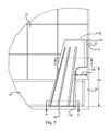
FIG. 7 is a front view of a shower stall with a support surface.
FIG. 8 is a cross-section view A-A as shown in FIG. 7 of a support surface.
FIG. 9 is a cross-section view B-B as shown in FIG. 7 of a support surface.
FIG. 10 is a cross-section view C-C as shown in FIG. 3 of a support surface located in a shower.
FIGS. 11A-11D are back perspective views of support surfaces showing various friction surfaces.
DETAILED DESCRIPTION
This invention relates to home furnishings and accessories that utilize corner space of a shower stall as a support platform. The support platform may include a top support surface with two sides positioned to contact two perpendicular walls of the corner. A support frame may connect to the top support surface such that the bottom of the support frame and the top support surface are offset from one another. This offset configuration of the support platform may prevent the support frame for interfering with anything in the area directly below the top support surface.
In accordance with various embodiments, as illustrated in FIG. 1, a corner support structure 100 may include a top support surface 110. The top support surface 110 may be operable to support an item on its upper surface. The top surface 110 may be smooth or textured to provide for additional traction. For example, the top surface 110 may include texture grooves 112. (Also shown in FIG. 3) The texture grooves 112 may be contours in the surface. The contours may be included at the time of manufacture such as in a plastic injection molding tool. Alternatively the texture grooves may be machined into the surface after manufacture of the corner support structure 100. The surface may also be textured by applying a textured coating to the surface after manufacture of corner support structure 100. The corner support structure 100 may further include a contact surface 130 and a contact surface 160. The top support surface 110 and the contact surfaces 130/160 may be connected. The connection may be at transition 105. Transition 105 may be any variety of connection between surfaces residing in different planes. For example, transition 105 may be a round, flat, or line connection between top support surface 110 and contact surfaces 130/160.
In accordance with various embodiments, the contact surface 130 and the contact surface 160 may be perpendicular to one another. However, in other embodiments, the contact surface 130 and the contact surface 160 may reside at angles to one another that reflect an angle between two walls for which the corner support structure is used. The contact surface 130 and the contact surface 160 may intersect at a transition 135. In various embodiments, transition 135 may be a round transition from contact surface 130 to contact surface 160. In other embodiments, transition 135 may be a flat transition from contact surface 130 to contact surface 160, forming another wall. Such a flat transition may avoid interfering with the profile of the intersection corner between two walls for which the corner support structure is used. As discussed in more detail below, contact surfaces 130 and 160 may further include traction pads 132/162 adhered to their surface.
Corner support structure 100 may also include one or more walls that extend from the bottom of the corner support structure 100 up top support surface 110. The one or more walls may include an interior wall 170. In one embodiment, interior wall 170 may be substantially vertical. This orientation may aid in manufacturing the corner support structure with a straight pull plastic injection molding process. In another embodiment, interior wall 170 may angle away from the top support surface 110. Alternatively, interior wall 170 may angle under the top support surface 110. In one example, the wall 170 may extend up from the bottom of corner support structure 100 to the top support surface 110. The one or more walls may further include side walls 150/180. Side walls may be connected at either side of the interior wall 170. As illustrated in FIG. 2, the one or more walls may further include an exterior wall 140. Exterior wall 140 may be connected to side walls 150/180. In accordance with various embodiments, the side walls 150/180, exterior wall 140 and interior wall 170 may form a support frame for top support surface 110, contact surface 160 and contact surface 130. At the bottom of this support frame, the bottom edges of the side walls 150/180, the exterior wall 140, and the interior wall 170 all end in the same plane (i.e. the bottom plane of the corner support structure 100) forming a structure that may contact a floor 20 flatly. In accordance with various embodiments, a base member 120 may be attached to the bottom edges of the walls.
The support frame may have various reinforcing features. For example, as illustrated in FIGS. 2 and 3, exterior wall 140 may include ribs 142. The ribs 142 may extend along the height of exterior wall 140. While illustrated with respect to exterior wall 140, ribs may also reinforce the rest of the support frame such that support frame does not collapse under a force exerted on the top surface 110.
As illustrated in FIG. 2, the exterior wall 140 may reside at an angle 149 relative to the bottom plane of the corner support structure 100. The angle 149 may be from 30 degrees to 90 degrees. For example, in one embodiment, the angle may be 74 degrees. It may be noted that the angle may vary based on the height of the corner support structure 100, the area of the top support surface 110, and the area of the bottom of the corner support structure 100 takes up, such as the area of the base member 120. Variation in the angle 149 may be utilized to position the top support surface so that it is not directly above the bottom of the support frame and/or the base member 20. One of ordinary skill in the art may be able to calculate the angle in order to place the bottom of the support frame in the desired position relative to the top surface. In other embodiments, the top support surface 110 may be positioned partially over the bottom of the support frame/base member 20.
As illustrated in FIGS. 1-2, the contact surfaces 130/160 may only extend to length 137, which may be a portion of the height of support structure 100. The contact surfaces 130/160 may begin at a length of 136 from the bottom of the support structure 100. By beginning at length 136, the contact surfaces may avoid interfering with any protrusions at the base of the wall that the contact surfaces 130/160 contact. For example, length 136 may be greater than the height of the rim or curb of the basin in a shower stall such as curb 40/50 illustrated in FIGS. 6-7. Length 136 may be 3-12 inches tall. More specifically length 136 may be about 7 inches tall. Length 136 and length 137 may be combined to be a suitable height for utilizing the corner support. For example, in a shower stall use, length 136 and 137 may be combined to be 8-18 inches. More specifically, length 136 and 137 may be combined to be about 13-14 inches tall.
As the contact 130/160 surfaces may not extend to the bottom of the support frame, elements of the support frame may flare out in order to connect to the contact surfaces. As such, the exterior wall 140 may have wings 152/162. The wings 152/162 include a portion of the exterior wall 140 near the top that attaches to contact surfaces. As illustrated in FIGS. 1-2 wings 152/162 may flare out from exterior wall 140 in order to connect the exterior wall 140 to the contact surfaces 130/160 respectively. The contact surface 130/160 and the exterior wall 140 may intersect at a transitions 144/146 respectively. In various embodiments, transitions 144/146 may be round transitions from contact surfaces 130/160 to exterior wall 140. In other embodiments, transitions 144/146 may be flat transitions.
FIG. 3 illustrates a top view of the corner support 112. As shown herein the texture grooves 112 (also discussed above) may extend across the top surface 100 providing increased friction/traction for anything that comes into contact with the surface. In accordance with various embodiments, as illustrated in FIG. 3, the exterior wall 140 may have a convex curvature extending away from top surface 110. Similarly illustrated in the bottom view of FIGS. 4 and 5, the corner support 100 may be formed in a shape that is a fraction of a circle. While the contact surfaces 130/140 may be perpendicular (or custom formed to the specific angle between two walls where the corner support 100 will be used) as indicated by angle 220, the shape of the structure between these two walls may form the arcs of a circle extending out (the corner support 100 may also be other shapes such as square, triangular, oval, or any unique and custom profile.) For example, from transition 135 out to interior wall 170 may be radius 230. From transition 135 out to exterior wall 140 may be radius 240. Radius 230 may be sufficient to clear any protrusion from the various walls adjacent to the corner support 100. Radius 240 may be sufficient to provide enough surface area to support the device and also enough surface area to provide sufficient traction from a traction pad to keep the corner support device 100 from sliding away from the walls. In various examples, radius 230 may be between 2 and 9 inches. More specifically, radius 230 may be between 5-6 inches. In various examples, radius 240 may be between 4 and 12 inches. More specifically, radius 240 may be between 8-9 inches. In one specific example, radius 230 may be about 5.5 inches and radius 240 may be about 8.3 inches.
In accordance with various embodiments, the angle 210 between side walls 150 and 180 may be less than the angle 220 between contact surfaces 130 and 160. By having the angle 210 between side walls 150 and 180 be less than the angle 220 between contact surfaces 130 and 160, the side walls may avoid interfering with any protrusions as the base of the shower stall. In one example, the angle 210 between side walls 150 and 180 may be from 10-80 degrees. More specifically, the angle 210 may be 40-60 degrees. In one specific example, the angle 210 may be 50 degrees.
By forming the corner support in a circular shape (or at least a portion of a circular shape) that floor area that the corner support 100 takes up is minimalized while the contact area of the corner support with the floor is maximized. This achieves a good balance between usefulness and taking up an efficient amount of space in the corner where the device is utilized.
In accordance with various embodiments, as illustrated in FIG. 6 and alluded to above, a corner support structure 100 may be utilized in any situation in which two walls come together, such as wall 30 and wall 60. The corner support structure 100 may lean against the walls 30/60 near the location in which they meet. The corner support structure 100 may also be supported by a floor 20. At the top of the corner support structure 100, a support surface 110 may be suitably located to support an object on the top of the corner support structure 100. As illustrated in FIG. 6 the object may be a person's leg 10. It may be noted that the corner support structure 100 may be operable to support any object however as the figures utilize a shower stall as an example location for use of the corner support, the example object will be discussed herein with reference to a person's leg 10.
The person's leg 10 may create a downward force, illustrated by arrow D in FIG. 6, on the corner support structure 100. The resultant forces of the corner support structure 100 against the walls and floor are represented by arrows A, B, and C. Side surfaces of the corner support structure 100 are forced against the walls 30/60 along arrows B and C. A downward force drives the bottom of the corner support structure 100 against the floor. The downward force D is applied against the top support surface 110. However, according to various embodiments and further discussed herein, the top support surface may not be located directly above the bottom of the corner support structure 100 where the downward force A is located. Nonetheless, the geometry of the corner support structure 100 allows the unit to maintain its position without slipping.
In accordance with various embodiments, as illustrated in FIG. 7, the corner support structure 100 may include a contact surface 130 located on the vertical side of the corner support structure 100. The contact surface 130 may be located such that it may contact the vertical wall 30. The contact surface 130 may connect with top support surface 110. In various embodiments, the support surface 110 and the contact surface 130 may be perpendicular. However, in other embodiments, top support surface 110 may not be perpendicular to contact surface 130 as it may be more or less than 90 degrees offset from the contact surface 130.
As shown in FIG. 7, the corner support structure 100 may further include a base element 120. Base element 120 may be positioned at the bottom of the corner support structure 100. In one embodiment, base element 120 may be in direct contact with the floor. In another embodiment, base element 120 may include traction pad 122, which may in turn be in direct contact with floor 20. In yet another embodiment, the bottom of corner support structure 100 may be in direct contact with the floor 20 or the bottom of the corner support structure 100 may include a traction pad.
In high friction environments, the contact surface, base member, or the corner support structure may be configured without a traction and contact the structural features of the environment directly, such as contact surface 130 directly against wall 30. However, in low friction environments, such as a shower stall, where water on hard surfaces makes slipping of the corner support structure 100 more likely, the contact surface, base member, or the corner support structure may include a traction pad, with the traction pad making direct contact with the environment support features such as traction pad 132 directly against wall 30.
In accordance with various embodiments, as illustrated in FIG. 7, a side wall of the corner support structure 100 is offset from the contact surface 130 according to relative position 134. This relative position 134 is greater than the typical structural features that protrude out from wall 30 such as a base board 50. Also shown in FIG. 7, the contact surface 130 may not extend all the way from the bottom of the support frame surface 130 to the floor 120. Instead, the end of the contact surface 130 may be offset from the bottom of the support frame as indicated by relative position 136. It may be noted that the relative positions 134 and 136 may be adjusted to any distance such that the bottom portion of the corner support 100 avoids contact with protrusions from walls 30/60 such as base boards 50/40 (e.g. the raised portion of a shower basin as specifically shown in 50/40 of FIGS. 6-7.
In accordance with various embodiments, as illustrated in the cross section of FIG. 8, as discussed above, the corner support structure 100 may be located in the corner of two walls 20/30 with traction pads 162/132 exerting a force against walls 20/30 along arrows B and C respectively. As illustrated herein, the exterior wall 140, the contact surface 130, and the contact surface 160 form the sides around volume 190 (also shown in FIG. 10). Volume 190 may be formed as a part of a straight tooling pull of the mold that may form the corner support platform 100. In accordance with various embodiments, as illustrated in FIG. 9, the bottom of the support frame and/or the base element is offset (i.e. not in contact with) the base boards 50/40. This cross section also highlights the embodiment in which interior wall 170, exterior wall 140, and side walls 180/150 together form the volume 195 (also shown in FIG. 10). Volume 195 may be formed as part of a straight tooling pull of the mold thus forming a useful device while simplifying manufacturing.
In accordance with various embodiments, the corner support 100 may include a traction pad such as those illustrated in FIGS. 11A-11D. For example, a circular traction pad 132A and circular traction pad 132B, shown in FIG. 11A, may be adhered to the face of the contact surface 130 and the contact surface 160 respectively. In another example, dual strips of traction pad such as traction pads 132B and 162B, shown in FIG. 11B, may be adhered to the face of the contact surface 130 and the contact surface 160 respectively. In another example, a plurality of circular traction pads such as traction pads 132C and 162C, shown in FIG. 11C, may be adhered to the face of the contact surface 130 and the contact surface 160 respectively. In another example, rectangular traction pads such as traction pads 132D and 162D, shown in FIG. 11D, may be adhered to the face of the contact surface 130 and the contact surface 160 respectively. As discussed above and similarly illustrated in FIG. 7, the base member 120 may similarly include a traction pad 122. This traction pad may be similar in shape to those discussed above or as shown in FIG. 7, the traction pad 122 may be formed the same shape as the base member 120 (while not shown traction pads 132/162 may likewise take the shape of their respective surfaces). The traction pads 122, 132, and 162 may cover a substantial area of the contact surfaces 122/130/160, such as more than half of their respective surface area. In other embodiments, the traction pads 122, 132, and 162 may cover very little of the surfaces 120/130/160, such as less than a quarter. Alternatively the pads may also occupy any range in-between.
The traction pads 122/132/162 are located in areas that touch the surrounding support structure, such as the shower walls 30/60 and the shower floor 20. As such, the traction pads 122/132/162 may be specifically selected to limit the ability of the contact surfaces 130/160 to slip relative to the surrounding support structure which they contact such as shower walls 30/60 or shower floor 20. The traction pads may be made from any traction improving material. For example, when used in a wet environment with hard surfaces such as a shower, the traction pads may be formed from a nonslip material such as neoprene rubber, but any material may be used. On other surfaces such as carpet more aggressive traction cleats may be utilized. In accordance with the various embodiments discussed herein, any traction improving surface may be utilized.
The corner support structure as described herein may be formed using plastic materials including, but not limited to, polyethylene (PE), polypropylene (PP), polyvinyl chloride (PVC), acrylonitrile butadiene styrene (ABS), poly carbonate (PC), polyamide (PA), polybutylene terephthalate (PBT), and so on. In various embodiments, the corner support structure may be manufactured using any process including, but not limited to, plastic injection molding, vacuum forming, 3d printing, machining, and so on.
In accordance with one specific example of the corner support structure 100, a base assembly comprises a base mechanically coupled to a base pad. The base pad has the shape of an inner arc mechanically coupled to an outer arc by two lines connecting the inner arc to the outer arc. The base is mechanically coupled to a support frame. The support frame has the shape of a partially rounded front portion mechanically coupled to a side portion. The side portion is mechanically coupled to side pads that can support the support frame against a wall. The side portion and the front portion are mechanically coupled to a top portion. The top portion is mechanically coupled to a foot rest surface. The base is injection molded acrylonitrile butadiene styrene (ABS). The base pad may be a die cut ⅛ inch thick adhesive backed non-slip neoprene rubber. The foot rest surface comprises shallow ribs for non-slip. The side pads may be two die cut ⅛ inch thick adhesive backed non-slip neoprene rubber pads. In accordance with various embodiments, one or more of the elements of the support platform may be injection molded ABS. For example the base member and/or the support frame may be injection molded. While in some embodiments the base pads and side pads may be applied to the support platform structure with an adhesive, in other embodiments, the base pads and side pads may be formed as part of the device during the injection molding process. For example, the base pads and side pads may be insert molded or over-molded into the base member and support frame respectively during the injection molding process.
It should be noted that all directional and/or dimensional references (e.g., upper, lower, upward, downward, left, right, leftward, rightward, top, bottom, above, below, front, back, rear, forward, backward, rearward, inner, outer, inward, outward, vertical, horizontal, clockwise, counterclockwise, length, width, height, depth, and relative orientation) are only used for identification purposes to aid the reader's understanding of the implementations of the disclosed invention(s), and do not create limitations, particularly as to the position, orientation, use, relative size or geometry of the invention(s) unless specifically set forth in the claims.
Connection references (e.g., attached, coupled, connected, joined, and the like) are to be construed broadly and may include intermediate members between a connection of elements and relative movement between elements. As such, connection references do not necessarily infer that two elements are directly connected and in a fixed relation to each other.

Claims (14)

We claim:
1. A corner support comprising:
a support platform having a top support surface, with the support platform having two sides that are positioned to contact two perpendicular walls which are each perpendicular to the floor;
a support frame which connects to the top support surface such that the bottom of the support frame and the top support surface are not aligned but are offset from one another such that the area directly below the top support surface is not occupied by the bottom of the support frame, wherein the support frame comprises one or more walls connecting to and extending from each exterior side of a perimeter of a base member, wherein the bottom of the base member is the only contact with the floor and a first wall of the one or more walls is substantially vertical and a second wall which opposes the first wall extends from the base member at an angle up to the top of the support platform.
2. A corner support of claim 1, wherein the support platform extends away from the first wall.
3. A corner support of claim 2, wherein the two sides connect to the second wall.
4. A corner support of claim 1, wherein the two sides, the support platform, and a plurality of the walls of the support frame form a first hollow cavity and the walls of the support frame form a second hollow cavity within the support frame such that the corner support is formable with a straight pull mold.
5. The corner support of claim 1, wherein the two sides include traction pads which are configured to contact the two perpendicular walls respectively and wherein the traction pads are configured to limit the downward movement of the two sides relative to the two perpendicular walls.
6. The corner support of claim 5, wherein a face of at least one of the sides includes a recessed area for receiving one of the traction pads.
7. The corner support of claim 1, wherein the top support surface includes a plurality of recessed grooves.
8. The corner support of claim 7, wherein the plurality of recessed grooves are separated by shallow ribs forming a non-slip surface to support a foot.
9. The corner support of claim 1, further comprising a base member which is connected to the bottom of the support frame and configured to contact a floor.
10. The corner support of claim 9, wherein the base member includes a traction surface that is configured to contact the floor.
11. The leg support of claim 10, wherein the traction surface is defined by a base pad that includes an adhesive backed non-slip neoprene rubber.
12. The corner support of claim 1, wherein the support frame has a convex surface connecting the two sides.
13. The leg support of claim 12, wherein the convex surface is a part of the outer wall.
14. The leg support of claim 1, wherein the base module is injection molded acrylonitrile butadiene styrene.
US14/065,917 2012-10-30 2013-10-29 Corner support platform Active 2034-03-01 US9414719B2 (en)

Priority Applications (1)

Application Number Priority Date Filing Date Title
US14/065,917 US9414719B2 (en) 2012-10-30 2013-10-29 Corner support platform

Applications Claiming Priority (2)

Application Number Priority Date Filing Date Title
US201261720053P 2012-10-30 2012-10-30
US14/065,917 US9414719B2 (en) 2012-10-30 2013-10-29 Corner support platform

Publications (2)

Publication Number Publication Date
US20140115774A1 US20140115774A1 (en) 2014-05-01
US9414719B2 true US9414719B2 (en) 2016-08-16

Family

ID=50545536

Family Applications (1)

Application Number Title Priority Date Filing Date
US14/065,917 Active 2034-03-01 US9414719B2 (en) 2012-10-30 2013-10-29 Corner support platform

Country Status (1)

Country Link
US (1) US9414719B2 (en)

Cited By (1)

* Cited by examiner, † Cited by third party
Publication number Priority date Publication date Assignee Title
US20180252038A1 (en) * 2017-03-06 2018-09-06 Michael McGarey Portable step device and method

Families Citing this family (1)

* Cited by examiner, † Cited by third party
Publication number Priority date Publication date Assignee Title
AU2013205085A1 (en) * 2013-02-22 2014-09-11 Leanne Therese Brown Shaver step

Citations (56)

* Cited by examiner, † Cited by third party
Publication number Priority date Publication date Assignee Title
US1019775A (en) 1911-02-24 1912-03-12 Frederick Forsberg Foot-rest for bath-tubs.
US1232223A (en) 1916-10-04 1917-07-03 Bathtub Foot Rest Corp Bath-tub foot-rest.
US1265609A (en) 1916-08-12 1918-05-07 Charles A Carry Foot-rest.
US2127762A (en) * 1937-09-14 1938-08-23 George B Bentz Bathtub seat attachment
US2818577A (en) * 1956-07-03 1958-01-07 Stanley S Kubik Foot support for shower baths
US3275283A (en) 1965-10-18 1966-09-27 Lauren F Rauch Folding foot rest
US3396413A (en) 1965-05-10 1968-08-13 Kaufman William Footrest
US3713180A (en) 1970-12-18 1973-01-30 P Martin Foot support for shower baths
US4356575A (en) 1980-11-26 1982-11-02 Terry Linda T Kneeling appliance for use with bathtubs
US4489448A (en) 1983-05-10 1984-12-25 Cairo John B Foot support for showers
US4493712A (en) 1982-09-28 1985-01-15 Kampff Ronald J Foot soaker and rester
USD287075S (en) 1984-09-11 1986-12-09 George M. Colin Combined shower stall foot stool and storage compartment
USD289840S (en) 1984-05-24 1987-05-19 Calvin Burkes Bathtub table
US4994648A (en) 1989-08-07 1991-02-19 Yamila Gil Device for supporting a user's leg
US5224224A (en) 1991-01-11 1993-07-06 Kohler Co. Foot bathing fixture
US5228151A (en) 1991-09-30 1993-07-20 Livingston Capoano Barbara D Foot support for showers and bath
USD340508S (en) 1991-10-01 1993-10-19 Hocker Debra S Shower foot rest
US5331693A (en) 1992-09-21 1994-07-26 Petersen Kimberlee C Lady's footrest for use in the bath
US5337525A (en) 1992-03-06 1994-08-16 Herman Miller, Inc. Rail system
US5340070A (en) 1993-07-21 1994-08-23 Soma Betsy A Leg shave plate
US5341528A (en) 1993-03-11 1994-08-30 Caroline Sultzbaugh Foot rest for use in a shower
USD351647S (en) 1993-03-11 1994-10-18 Caroline Sultzbaugh Foot rest for showers
US5425149A (en) 1994-01-28 1995-06-20 Safety 1St, Inc. Fold-up bathtub
US5465435A (en) 1995-02-21 1995-11-14 Malvaez; Laura A. Shower step for shaving legs
US5579545A (en) 1995-05-05 1996-12-03 Janeen E. Beard Combined foot support and grooming needs holder
US5647072A (en) 1995-08-16 1997-07-15 Shaffer; Pauline S. Foot support device for shower areas
US5732421A (en) 1996-01-30 1998-03-31 Scherberger; Lutz A. Shower seat
USD400382S (en) 1997-07-11 1998-11-03 Wendt Allen L Wall-mounted footrest
USD404475S (en) * 1997-01-22 1999-01-19 Barbara Livingston-Capoano Foot support for showers
US5920926A (en) 1997-09-30 1999-07-13 Torres; Colleen Petruzz Easy shave foot support
US6029291A (en) 1998-10-19 2000-02-29 Livingston-Capoano; Barbara Integrated foot support for showers
USD422687S (en) 1997-01-31 2000-04-11 Barbara Livingston-Capoano Foot support for showers
US6065251A (en) * 1994-09-22 2000-05-23 Kindrick; Ronald Steven Bath bench
US6094756A (en) 1999-04-22 2000-08-01 Carter; Carolyn Shower Chair
US6115857A (en) 1999-07-12 2000-09-12 Bidegain; Marty E. Foot support
US6301725B1 (en) 1999-01-06 2001-10-16 Brian Harvey Corner shower seat
US6532969B2 (en) 2001-02-15 2003-03-18 Marketing Productions, Inc. Self-pedicure unit including contoured foot support and internal storage compartments
USD487533S1 (en) 2002-09-09 2004-03-09 Phillip G. Abbott Pedicure footrest
US6848368B2 (en) * 2001-01-12 2005-02-01 John Russ Leith Stand device
US20060036198A1 (en) 2004-08-10 2006-02-16 Helen Of Troy Limited Foot spa
US20060143820A1 (en) 2004-08-03 2006-07-06 Matthews Pamela J Shower stool
US20060207010A1 (en) 2005-03-15 2006-09-21 Alsons Corporation Footrest waterfall shower
US20070163039A1 (en) 2005-12-28 2007-07-19 Lee Shun C Device for supporting a foot
US7266851B1 (en) 2006-09-20 2007-09-11 Batalini Renee A Foot support
US7310837B2 (en) 2003-10-06 2007-12-25 Ellie Situpon, Inc. Bathtub/shower seat
US20090183305A1 (en) 2008-01-18 2009-07-23 Edsa Sampaio Feet hold device
US20090189432A1 (en) 2008-01-26 2009-07-30 Sergey Anikin Self-inflatable footrest
US20110018327A1 (en) 2007-12-24 2011-01-27 Mohamed Hosny Abolkheir Footstool
US7886376B2 (en) 2007-02-20 2011-02-15 Kerrie Lynn Ray Shower cube with shaving buddy
US7950078B2 (en) 2007-07-23 2011-05-31 Robin Houpt Preformed structural support for tile
US7987535B1 (en) 2009-05-13 2011-08-02 Theodore Allen Tesch Shower corner seat assembly
US20110252561A1 (en) * 2010-04-14 2011-10-20 Garrels Clayton C Movable Seat for Shower Stall
US20110308007A1 (en) 2010-06-16 2011-12-22 Kelly Gray Stevens Shower footrest
US8161700B2 (en) 2010-01-14 2012-04-24 Scalise David H Tiled structures and brackets therefor
US8225435B2 (en) 2008-01-22 2012-07-24 Noble Company Shower bench
US8628143B2 (en) * 2009-11-17 2014-01-14 Kristin Wald Corner-braced, portable, foot prop

Patent Citations (56)

* Cited by examiner, † Cited by third party
Publication number Priority date Publication date Assignee Title
US1019775A (en) 1911-02-24 1912-03-12 Frederick Forsberg Foot-rest for bath-tubs.
US1265609A (en) 1916-08-12 1918-05-07 Charles A Carry Foot-rest.
US1232223A (en) 1916-10-04 1917-07-03 Bathtub Foot Rest Corp Bath-tub foot-rest.
US2127762A (en) * 1937-09-14 1938-08-23 George B Bentz Bathtub seat attachment
US2818577A (en) * 1956-07-03 1958-01-07 Stanley S Kubik Foot support for shower baths
US3396413A (en) 1965-05-10 1968-08-13 Kaufman William Footrest
US3275283A (en) 1965-10-18 1966-09-27 Lauren F Rauch Folding foot rest
US3713180A (en) 1970-12-18 1973-01-30 P Martin Foot support for shower baths
US4356575A (en) 1980-11-26 1982-11-02 Terry Linda T Kneeling appliance for use with bathtubs
US4493712A (en) 1982-09-28 1985-01-15 Kampff Ronald J Foot soaker and rester
US4489448A (en) 1983-05-10 1984-12-25 Cairo John B Foot support for showers
USD289840S (en) 1984-05-24 1987-05-19 Calvin Burkes Bathtub table
USD287075S (en) 1984-09-11 1986-12-09 George M. Colin Combined shower stall foot stool and storage compartment
US4994648A (en) 1989-08-07 1991-02-19 Yamila Gil Device for supporting a user's leg
US5224224A (en) 1991-01-11 1993-07-06 Kohler Co. Foot bathing fixture
US5228151A (en) 1991-09-30 1993-07-20 Livingston Capoano Barbara D Foot support for showers and bath
USD340508S (en) 1991-10-01 1993-10-19 Hocker Debra S Shower foot rest
US5337525A (en) 1992-03-06 1994-08-16 Herman Miller, Inc. Rail system
US5331693A (en) 1992-09-21 1994-07-26 Petersen Kimberlee C Lady's footrest for use in the bath
USD351647S (en) 1993-03-11 1994-10-18 Caroline Sultzbaugh Foot rest for showers
US5341528A (en) 1993-03-11 1994-08-30 Caroline Sultzbaugh Foot rest for use in a shower
US5340070A (en) 1993-07-21 1994-08-23 Soma Betsy A Leg shave plate
US5425149A (en) 1994-01-28 1995-06-20 Safety 1St, Inc. Fold-up bathtub
US6065251A (en) * 1994-09-22 2000-05-23 Kindrick; Ronald Steven Bath bench
US5465435A (en) 1995-02-21 1995-11-14 Malvaez; Laura A. Shower step for shaving legs
US5579545A (en) 1995-05-05 1996-12-03 Janeen E. Beard Combined foot support and grooming needs holder
US5647072A (en) 1995-08-16 1997-07-15 Shaffer; Pauline S. Foot support device for shower areas
US5732421A (en) 1996-01-30 1998-03-31 Scherberger; Lutz A. Shower seat
USD404475S (en) * 1997-01-22 1999-01-19 Barbara Livingston-Capoano Foot support for showers
USD422687S (en) 1997-01-31 2000-04-11 Barbara Livingston-Capoano Foot support for showers
USD400382S (en) 1997-07-11 1998-11-03 Wendt Allen L Wall-mounted footrest
US5920926A (en) 1997-09-30 1999-07-13 Torres; Colleen Petruzz Easy shave foot support
US6029291A (en) 1998-10-19 2000-02-29 Livingston-Capoano; Barbara Integrated foot support for showers
US6301725B1 (en) 1999-01-06 2001-10-16 Brian Harvey Corner shower seat
US6094756A (en) 1999-04-22 2000-08-01 Carter; Carolyn Shower Chair
US6115857A (en) 1999-07-12 2000-09-12 Bidegain; Marty E. Foot support
US6848368B2 (en) * 2001-01-12 2005-02-01 John Russ Leith Stand device
US6532969B2 (en) 2001-02-15 2003-03-18 Marketing Productions, Inc. Self-pedicure unit including contoured foot support and internal storage compartments
USD487533S1 (en) 2002-09-09 2004-03-09 Phillip G. Abbott Pedicure footrest
US7310837B2 (en) 2003-10-06 2007-12-25 Ellie Situpon, Inc. Bathtub/shower seat
US20060143820A1 (en) 2004-08-03 2006-07-06 Matthews Pamela J Shower stool
US20060036198A1 (en) 2004-08-10 2006-02-16 Helen Of Troy Limited Foot spa
US20060207010A1 (en) 2005-03-15 2006-09-21 Alsons Corporation Footrest waterfall shower
US20070163039A1 (en) 2005-12-28 2007-07-19 Lee Shun C Device for supporting a foot
US7266851B1 (en) 2006-09-20 2007-09-11 Batalini Renee A Foot support
US7886376B2 (en) 2007-02-20 2011-02-15 Kerrie Lynn Ray Shower cube with shaving buddy
US7950078B2 (en) 2007-07-23 2011-05-31 Robin Houpt Preformed structural support for tile
US20110018327A1 (en) 2007-12-24 2011-01-27 Mohamed Hosny Abolkheir Footstool
US20090183305A1 (en) 2008-01-18 2009-07-23 Edsa Sampaio Feet hold device
US8225435B2 (en) 2008-01-22 2012-07-24 Noble Company Shower bench
US20090189432A1 (en) 2008-01-26 2009-07-30 Sergey Anikin Self-inflatable footrest
US7987535B1 (en) 2009-05-13 2011-08-02 Theodore Allen Tesch Shower corner seat assembly
US8628143B2 (en) * 2009-11-17 2014-01-14 Kristin Wald Corner-braced, portable, foot prop
US8161700B2 (en) 2010-01-14 2012-04-24 Scalise David H Tiled structures and brackets therefor
US20110252561A1 (en) * 2010-04-14 2011-10-20 Garrels Clayton C Movable Seat for Shower Stall
US20110308007A1 (en) 2010-06-16 2011-12-22 Kelly Gray Stevens Shower footrest

Cited By (1)

* Cited by examiner, † Cited by third party
Publication number Priority date Publication date Assignee Title
US20180252038A1 (en) * 2017-03-06 2018-09-06 Michael McGarey Portable step device and method

Also Published As

Publication number Publication date
US20140115774A1 (en) 2014-05-01

Similar Documents

Publication Publication Date Title
USD877544S1 (en) Height adjustable desk with I shaped legs
USD887934S1 (en) Floor mat
USD907397S1 (en) Corner shower caddy
USD937168S1 (en) Vehicle floor mat
USD857242S1 (en) Architectural wall tile with three dimensional elongated hexagon surface
USD857929S1 (en) Architectural wall tile with three dimensional hexagon surface
USD937169S1 (en) Vehicle floor mat
USD938755S1 (en) Water ripple non-slip bathroom floor mat
USD940031S1 (en) Vehicle floor mat
USD908388S1 (en) Corner shower caddy
USD569668S1 (en) Shower caddy
USD972083S1 (en) Shower head
USD568656S1 (en) Shower caddy
USD574513S1 (en) Floor/wall finish molding
JP6355064B2 (en) Bathroom structure
US8820023B2 (en) Block deck using concrete
US9414719B2 (en) Corner support platform
US20080067003A1 (en) Step-stool assemblies with continuous outer shells and related methods
USD568496S1 (en) Corner molding for wall and roof coverings
USD874684S1 (en) Architectural wall tile with three dimensional diamond surface
USD603616S1 (en) Stackable chair
USD594575S1 (en) Baseboard molding trim
USD857928S1 (en) Architectural wall tile with three dimensional concave surface
USD904041S1 (en) Winged sofa with square legs
JP2009108579A (en) Prefabricated floor material

Legal Events

Date Code Title Description
AS Assignment

Owner name: 2M PRODUCTS, LLC, COLORADO

Free format text: ASSIGNMENT OF ASSIGNORS INTEREST;ASSIGNORS:GAY, MICHAEL LEE;ECHELBERGER, MICHELLE ANN;REEL/FRAME:031502/0651

Effective date: 20131023

STCF Information on status: patent grant

Free format text: PATENTED CASE

MAFP Maintenance fee payment

Free format text: PAYMENT OF MAINTENANCE FEE, 4TH YR, SMALL ENTITY (ORIGINAL EVENT CODE: M2551); ENTITY STATUS OF PATENT OWNER: SMALL ENTITY

Year of fee payment: 4

MAFP Maintenance fee payment

Free format text: PAYMENT OF MAINTENANCE FEE, 8TH YR, SMALL ENTITY (ORIGINAL EVENT CODE: M2552); ENTITY STATUS OF PATENT OWNER: SMALL ENTITY

Year of fee payment: 8