US9414025B2 - Method for intelligently displaying sports game video for multimedia mobile terminal - Google Patents
Method for intelligently displaying sports game video for multimedia mobile terminal Download PDFInfo
- Publication number
- US9414025B2 US9414025B2 US13/420,955 US201213420955A US9414025B2 US 9414025 B2 US9414025 B2 US 9414025B2 US 201213420955 A US201213420955 A US 201213420955A US 9414025 B2 US9414025 B2 US 9414025B2
- Authority
- US
- United States
- Prior art keywords
- shot
- location
- ball
- image frame
- long
- Prior art date
- Legal status (The legal status is an assumption and is not a legal conclusion. Google has not performed a legal analysis and makes no representation as to the accuracy of the status listed.)
- Expired - Fee Related, expires
Links
Images


Classifications
-
- H—ELECTRICITY
- H04—ELECTRIC COMMUNICATION TECHNIQUE
- H04N—PICTORIAL COMMUNICATION, e.g. TELEVISION
- H04N7/00—Television systems
- H04N7/18—Closed-circuit television [CCTV] systems, i.e. systems in which the video signal is not broadcast
-
- G—PHYSICS
- G06—COMPUTING; CALCULATING OR COUNTING
- G06T—IMAGE DATA PROCESSING OR GENERATION, IN GENERAL
- G06T3/00—Geometric image transformation in the plane of the image
- G06T3/40—Scaling the whole image or part thereof
- G06T3/4092—Image resolution transcoding, e.g. client/server architecture
-
- G06T7/0083—
-
- G—PHYSICS
- G06—COMPUTING; CALCULATING OR COUNTING
- G06T—IMAGE DATA PROCESSING OR GENERATION, IN GENERAL
- G06T7/00—Image analysis
- G06T7/10—Segmentation; Edge detection
- G06T7/12—Edge-based segmentation
-
- G—PHYSICS
- G06—COMPUTING; CALCULATING OR COUNTING
- G06T—IMAGE DATA PROCESSING OR GENERATION, IN GENERAL
- G06T2207/00—Indexing scheme for image analysis or image enhancement
- G06T2207/10—Image acquisition modality
- G06T2207/10016—Video; Image sequence
-
- G—PHYSICS
- G06—COMPUTING; CALCULATING OR COUNTING
- G06T—IMAGE DATA PROCESSING OR GENERATION, IN GENERAL
- G06T2207/00—Indexing scheme for image analysis or image enhancement
- G06T2207/20—Special algorithmic details
- G06T2207/20004—Adaptive image processing
-
- G—PHYSICS
- G06—COMPUTING; CALCULATING OR COUNTING
- G06T—IMAGE DATA PROCESSING OR GENERATION, IN GENERAL
- G06T2207/00—Indexing scheme for image analysis or image enhancement
- G06T2207/20—Special algorithmic details
- G06T2207/20112—Image segmentation details
- G06T2207/20132—Image cropping
-
- G—PHYSICS
- G06—COMPUTING; CALCULATING OR COUNTING
- G06T—IMAGE DATA PROCESSING OR GENERATION, IN GENERAL
- G06T2207/00—Indexing scheme for image analysis or image enhancement
- G06T2207/30—Subject of image; Context of image processing
- G06T2207/30221—Sports video; Sports image
- G06T2207/30224—Ball; Puck
Definitions
- the present invention relates to a display method for a multimedia mobile terminal, and more particularly to a method for intelligently displaying a sports game video which enables a non-long-shot is to be displayed through an entire frame thereof, but a long-shot is to be displayed through an enlargement of only a Region Of Interest (ROI) existing therein, so that the long-shot includes objects are seen in a smaller scale.
- ROI Region Of Interest
- FIG. 1 is a diagram illustrating a state in which a DMB phone receives and outputs soccer game broadcasting.
- most services are simply provided in an existing screen size.
- the ROI may be defined as a region in which users take a great interest on a screen or a region to which users pay much more attention than any other regions.
- designation of the ROI may be a first step for meaningfully analyzing a video scene, it is important technology in the field of image analysis.
- FIG. 2 is a diagram illustrating three types of shots existing in a sports game video.
- (a) indicates a long-shot
- (b) indicates a medium-shot
- (c) indicates a close-up shot.
- long-shot (a) it is necessary to extract, enlarge and reproduce an ROI.
- ROI determination in video has been researched based on brightness and darkness, color tone and motion information. In this research, they have proposed a method for indicating a most salient feature point in each image frame of video on an assumption that an important object has a high contrast in color tone or brightness and darkness. However, this assumption is not always correct because an important object may be dark or have a low contrast.
- a field sports video such as a soccer game includes both a shot requiring an extraction of an ROI and a shot not requiring the extraction of the ROI.
- small objects having considerable features simultaneously may exist within a screen.
- the present invention has been made to solve the above-mentioned problems occurring in the prior art and provides additional advantages, by providing a solution, in which, when a sports game video is displayed on a mobile terminal, a non-long-shot is displayed through an entire frame thereof, and a long-shot is displayed through the enlargement of only a ROI existing therein, so that viewers can more easily understand the video enjoy the video.
- a method for intelligently displaying a sports game video for a multimedia mobile terminal including the steps of: determining if a camera shot existing in the sports game video is a long-shot; when the camera shot is determined as a long-shot, determining a ROI within an image frame of the sports game video; and when the camera shot is determined as a non-long-shot, displaying the image frame on the mobile terminal, and, when the camera shot is determined as a long-shot, enlarging and displaying the ROI on the mobile terminal.
- FIG. 1 is a diagram illustrating a DMB phone receiving and outputting soccer game broadcasting
- FIG. 2 is a diagram illustrating three types of shots (long-shot, medium-shot and close-up shot) existing in a sports game video;
- FIG. 3 is a flow diagram illustrating an intelligent display method in a sports game video according to one embodiment of the present invention
- FIG. 4 is a diagram illustrating a histogram on a channel-by-channel basis in an HSV color space for a long-shot image in a sports game video according to the present invention
- FIG. 5 is a diagram illustrating a ground color identification process according to a method proposed by the present invention.
- FIG. 6 is a diagram illustrating an image after small holes existing in a ground block map are filled according to the present invention.
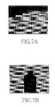
- FIG. 7 is a diagram illustrating a method for determining a long-shot or a non-long-shot by using a Longest Green Segment (LGS) in a sports game video processing process according to the present invention
- FIG. 8 is a diagram illustrating a sports game video processing process according to the present invention.
- FIG. 9 is a diagram illustrating the location determination step of a ROI window in a sports game video processing process according to the present invention.
- FIG. 10 is a diagram illustrating results of a sports game video processing process according to the present invention.
- a video may be defined as a sequence of shots as expressed by equation 1 below.
- the shot refers to an image sequence obtained through one-time camera recording process.
- Video ⁇ Shot 0 , . . . ,Shot K ⁇ 1 >, ( K is the number of video frames) Equation 1
- the shot may be expressed by a series of frames in equation 2 below.
- Shot K ⁇ f k 0 , . . . ,f k N ⁇ 1 > Equation 2
- f k i represents the i th frame of Shot k and N represents the number of frames in a shot.
- the i th frame will be expressed by f i throughout the video.
- the ROI of the i th frame of a k th shot may be expressed by ROI(f k i ). Further, the ROI may also be the whole or a part of an image frame depending on the type of a shot. That is, this may be expressed by equation 3 below.
- ROI( f k i ) ⁇ f k i , if Class(Shot k ) is a long-shot ROI( f k i ) f k i , if Class(Shot k ) is not a long-shot Equation 3
- FIG. 3 is a flow diagram illustrating an intelligent display method in a sports game video according to one embodiment of the present invention.
- the intelligent display method of the present invention includes a first process S 101 , S 103 , S 105 , S 107 , S 109 and S 111 , a second process S 113 , S 115 and S 117 , and a third process S 119 and S 121 .
- a first process whether a camera shot existing in a sports game video is a long-shot is determined.
- a ROI is determined within the image frame of the sports game video when the camera shot is a long-shot.
- the third process the entire image frame is displayed on a mobile terminal when the camera shot is a non-long-shot, and the ROI is enlarged and displayed on the mobile terminal when the camera shot is a long-shot.
- the first process includes steps 101 , 103 and 105 for learning a ground color in the sports game video, and steps 107 , 109 and 111 for extracting the ground color learned from the image frame and determining a long-shot or a non-long-shot according to comparison results with a preset reference value.
- step 107 the image frame is divided into (n ⁇ n) blocks to construct a ground block map.
- step 109 temporal block difference of the ground block map is checked to detect a shot boundary, and a segment having the longest ground color is found from each column of the ground block map within the detected shot boundary.
- step 111 a segment existing within a gold region of the image frame and having the longest ground color is compared with the preset reference value, and a long-shot or a non-long-shot is determined. A detailed process of steps 101 - 109 will be explained later.
- the second process includes steps 113 and 115 for finding the location of a ball in the image frame, and step 117 for computing a distance between the location of the ball found in steps 113 and 115 and a previous display window, primarily determining the location of the ROI based on the location of the ball, and finally determining the location of the ROI by changing the primarily determined location based on the computed distance.
- a binary image is constructed on a pixel basis with respect to the image frame, a connected component labeling of eight directions is performed for the binary image so as to obtain lists of each object according to the attributes of each object, a ball candidate list of the obtained lists is maintained, objects classified as a ball among newly found objects are added to the ball candidate list, and the location of an object shifted to a ball candidate in several frames is determined as the location of a ball in the ball candidate list.
- the color of the ground is important in the analysis of a soccer video. Particularly, this is important to determine the type of a shot.
- the amount of pixels expressing a ground color is an important clue for determining the types of a shot. It is necessary to learn a ground color of a video sequence in the first step of a system because the ground color slightly changes depending on the video sequence (S 101 ).
- FIG. 4 is an HSV histogram obtained from a long-shot of a general soccer video.
- FIGS. 4 a , 4 b , and 4 c indicate hue, saturation and value (brightness), respectively.
- hue values have been especially focused on the regions of yellow-green.
- saturation and value change depending on videos.
- the present invention implements the following ground color learning method.
- an HSV histogram for an i th frame may be defined by equation 4 below.
- the HSV histogram is accumulated and used over the first 30 frames of the video.
- this will be referred to as a HUE, a SATURATION and a VALUE and may be defined by equation 5 below.
- the number of frames over which the HSV histogram is accumulated may be changed without limit because it is a set value.
- ValuePeakIndex denotes the index of a bin having a peak value of a value histogram.
- Equation 9 the R, G, B values have been normalized to be a value between 0 and 1.
- the present invention has found the fact that the R, G, B values of most pixels corresponding to a ground has a correlation of g>r>b.
- Ground ⁇ ⁇ ( x , y ) ⁇ 1 if ⁇ ⁇ g > 0.95 ⁇ r ⁇ ⁇ and r > 0.95 ⁇ b ⁇ ⁇ and g ⁇ ValuePeakIndex + ⁇ 1 ⁇ ⁇ and g - b g ⁇ NS > SaturationMean - ⁇ 2 0 otherwise Equation ⁇ ⁇ 10
- r, g, b have values of 0 to 255 as RGB values in (x, y), and ⁇ 1 and ⁇ 2 have been set to NV/6 and NS/4, respectively.
- This method has a fast determination speed and is normally performed even when a shadow partially looms on a ground as illustrated in FIGS. 5 a and 5 c . Accordingly, it is possible to obtain color information capable of identifying ground colors as expressed by a black color in FIGS. 5 b and d (S 105 ).
- GB ⁇ ( i , j ) ⁇ 1 ⁇ ⁇ ( Ground ) if ⁇ ⁇ ⁇ ( x , y ) ⁇ B ij ⁇ ⁇ Ground ⁇ ⁇ ( x , y ) 16 ⁇ 16 ⁇ 0.2 0 ⁇ ⁇ ( Object ) otherwise Equation ⁇ ⁇ 12
- the ground block map of a frame will be expressed by GB (i, j) in the subsequent process.
- 20% which is a reference value for determining the ground color, may be changed without limit because it is a set value.
- Shot boundary detection is a basic process of video analysis. This is because the amount of calculation can be reduced by classifying shots only in a shot boundary and the accuracy of shot type determination can be improved by reducing the error of determination due to temporary change in a screen state.
- the Temporal Block Difference (TBD) of the ground block map is checked so as to detect a shot boundary efficiently and quickly.
- TBD i ⁇ x ⁇ ⁇ ⁇ y ⁇ ⁇ ⁇ GB i - 3 ⁇ ( x , y ) ⁇ GB i ⁇ ( x , y ) ⁇ Equation ⁇ ⁇ 13
- Equation 13 denotes an XOR operation.
- ⁇ ShortChange 30
- a condition of TBD i ⁇ 1 ⁇ ShortChange is added so as to reduce a boundary detection error.
- a current ground block map is compared with a ground block map before three frames. This is for coping with a case in which a shot gradually changes due to paid-in/out or visual effect.
- shot type determination must be performed at the point at which the shot boundary is detected.
- the present invention uses the ground block map. In the first step, holes occurring in a ground by soccer players as illustrated in FIG. 6 a must be filled as illustrated in FIG. 6 b . Details will be described as follows.
- the Longest Green Segment (LGS k ) is found with respect to each column k of the ground block map.
- the LGS k can be obtained by comparing length values of LGSs expressed in each column of FIGS. 7 a and 7 b . Then, the length of the LGS within a gold region (a central region corresponding to 5 when an image is divided by 3:5:3 in a horizontal direction) is measured, so that the type of a shot can be determined. As illustrated in FIG. 7 , if only one LGS smaller than ⁇ L exists, it is determined that a corresponding shot is not a long-shot. That is, it is determined that the shot of FIG. 7 a is a long-shot and the shot of FIG. 7 b is not a long-shot.
- Class ⁇ ( f ) ⁇ Non ⁇ - ⁇ long ⁇ - ⁇ shot , if ⁇ ⁇ ⁇ LGS k ⁇ ⁇ ⁇ L long ⁇ - ⁇ shot , otherwise ⁇ ⁇ for ⁇ ⁇ GSLeft ⁇ k ⁇ GSRight Equation ⁇ ⁇ 15
- ⁇ L is set to have a value of BlockslnColumn/3
- GSLeft is set to have a value of BlockslnRow ⁇ 3/11
- GSRight is set to have a value of BlockslnRow ⁇ 8/11.
- each frame is classified as a long-shot and a non-long-shot by equation 12.
- a non-long-shot it is not necessary to set a ROI smaller than an entire image frame. This is because display (S 121 ) of an entire frame is sufficient for the user.
- display (S 121 ) of an entire frame is sufficient for the user.
- a ROI it is necessary to set a ROI and then enlarge and reproduce the set ROI.
- the binary image is constructed on a pixel basis by using the Ground (x, y) of equation 10.
- FIG. 8 a A connected component labeling of eight directions is performed for this image, so that a list of objects within the ground can be obtained.
- FIG. 8 b Minimum Bounding Rectangles (MBRs) of the obtained objects are expressed by a yellow color.
- the objects are classified as a ball, a soccer player, a small object similar to a ball, and other objects according to the attributes (e.g. an aspect ratio, average brightness, the number of component pixels, etc.) of the objects.
- the present invention proposes a method capable of simply processing a broadcasting image in realtime, which is based on only previous values.
- a ball candidate tracked in the ground for the longest time period has a highest probability to be a ball. This can reduce temporary influence of noise.
- objects classified as balls among newly found objects are added to the current ball candidate list.
- the ball candidate is shifted to an object which is located adjacent to the ball candidate and has an attribute similar to that of the ball candidate. If the shifted object is a ball, the consecutive difference of the object increases. Otherwise, the consecutive difference of the object decreases. As a result, it is the most probable that an object having the highest consecutive difference corresponds to a ball. It is not necessary to track an object having a consecutive difference smaller than zero. Consequently, it is possible to correctly find a true ball with a high probability.
- the location of the most recently found ball is designated as the current location of a ball.
- the center of a screen is optionally designated as the location of a ball. It goes without saying that the three frames correspond to a reference value for optionally determining the location of a ball may be changed without limit because they are only a set value.
- the simplest method for arranging a ROI window is to place the center of the ROI window in the location of a ball.
- a screen may be shaken or the screen may move too fast in the opinion of a user.
- the ROI window must move smoothly.
- a method moving a display window in consideration of a case where a ball moves fast must include the concept of acceleration.
- the center of the ROI window is initialized to be the location of a ball as expressed by equation 17 below.
- window i lob i Equation 17
- disp i 0 i Equation 18
- window denotes the center of a display window in a frame f i
- lob i denotes the location of a ball in the frame f i
- disp i denotes a displacement by which the ROI window must actually move in the frame f i .
- Case 1 is a case in which a distance between the location of a ball and the center of the ROI window is shorter than a previous displacement. In this case, the location of the ROI window does not change. Instead, disp i is multiplied by a to obtain a reduced the value of disp i+1 .
- window i window i ⁇ 1 Equation 20
- disp i+1 ⁇ disp i (0 ⁇ 1) Equation 21
- the ROI window moves by disp i , and then disp i+1 is altered based on equation 23. Since
- window i window i ⁇ 1 +disp i Equation 22
- disp i+1 disp i + ⁇ 1 ⁇ sign(diff) Equation 23
- Case 3 is basically equal to case 2, but it has a larger acceleration parameter in order to cope with a case in which a ball moves too fast (0 ⁇ a 1 ⁇ a 2 ⁇ 1).
- window i window i ⁇ 1 +disp i Equation 24
- disp i+1 disp i + ⁇ 2 ⁇ sign(diff) Equation 25
- the display window must be processed as illustrated in FIG. 9 and shown to a user. After the display window is determined as (a), but it deviates from a frame, the location of the display window is altered and the content of the frame must be shown to a user as illustrated in (b) (S 119 ). In the above process, the used window, does not change.
- the present invention uses technology including a method of learning a specific ground color from a given video and detecting a ground area, an automatic detection method of a shot requiring the extraction of a ROI, an automatic designation method of a ROI in a shot requiring the ROI, etc., precisely selects images, in which objects are seen as being small, from a sports game vide, and displays only a ROI existing in the images, thereby enabling viewers to easily understand the images and to efficiently view the images.
Abstract
Description
Video=<Shot0, . . . ,ShotK−1>, (K is the number of video frames) Equation 1
ShotK =<f k 0 , . . . ,f k N−1> Equation 2
ROI(f k i)⊂f k i, if Class(Shotk) is a long-shot
ROI(f k i)=f k i, if Class(Shotk) is not a long-shot Equation 3
Huei [k]:0≦k<NH
Saturationi [k]:0≦k<NS
Valuei [k]:0≦k<NV Equation 4
ValuePeakIndex=i, where VALUE[k]≧VALUE[p] for all 0≦p≦NV, and Equation 6
This is because G≈Max(R,G,B) and B≈Min(R,G,B). In short, an equation for determining if each pixel belongs to a ground in a rgb color space may be expressed by equation 10 below.
B ij={(x,y)|i×16≦x<(i+1)×16,j×16≦y<(j+1)×16} Equation 11
windowi=lobi Equation 17
dispi=0i Equation 18
Diff=lobi−windowi−1 Equation 19
windowi=windowi−1 Equation 20
dispi+1=α·dispi(0<α<1) Equation 21
windowi=windowi−1+dispi Equation 22
dispi+1=dispi+α1·sign(diff) Equation 23
windowi=windowi−1+dispi Equation 24
dispi+1=dispi+α2·sign(diff) Equation 25
Claims (11)
Priority Applications (1)
| Application Number | Priority Date | Filing Date | Title |
|---|---|---|---|
| US13/420,955 US9414025B2 (en) | 2006-03-30 | 2012-03-15 | Method for intelligently displaying sports game video for multimedia mobile terminal |
Applications Claiming Priority (4)
| Application Number | Priority Date | Filing Date | Title |
|---|---|---|---|
| KR10-2006-0028802 | 2006-03-30 | ||
| KR1020060028802A KR100785952B1 (en) | 2006-03-30 | 2006-03-30 | An intelligent sport video display method for mobile devices |
| US11/528,114 US8164630B2 (en) | 2006-03-30 | 2006-09-27 | Method for intelligently displaying sports game video for multimedia mobile terminal |
| US13/420,955 US9414025B2 (en) | 2006-03-30 | 2012-03-15 | Method for intelligently displaying sports game video for multimedia mobile terminal |
Related Parent Applications (1)
| Application Number | Title | Priority Date | Filing Date |
|---|---|---|---|
| US11/528,114 Continuation US8164630B2 (en) | 2006-03-30 | 2006-09-27 | Method for intelligently displaying sports game video for multimedia mobile terminal |
Publications (2)
| Publication Number | Publication Date |
|---|---|
| US20120224748A1 US20120224748A1 (en) | 2012-09-06 |
| US9414025B2 true US9414025B2 (en) | 2016-08-09 |
Family
ID=37157371
Family Applications (2)
| Application Number | Title | Priority Date | Filing Date |
|---|---|---|---|
| US11/528,114 Expired - Fee Related US8164630B2 (en) | 2006-03-30 | 2006-09-27 | Method for intelligently displaying sports game video for multimedia mobile terminal |
| US13/420,955 Expired - Fee Related US9414025B2 (en) | 2006-03-30 | 2012-03-15 | Method for intelligently displaying sports game video for multimedia mobile terminal |
Family Applications Before (1)
| Application Number | Title | Priority Date | Filing Date |
|---|---|---|---|
| US11/528,114 Expired - Fee Related US8164630B2 (en) | 2006-03-30 | 2006-09-27 | Method for intelligently displaying sports game video for multimedia mobile terminal |
Country Status (2)
| Country | Link |
|---|---|
| US (2) | US8164630B2 (en) |
| KR (1) | KR100785952B1 (en) |
Families Citing this family (12)
| Publication number | Priority date | Publication date | Assignee | Title |
|---|---|---|---|---|
| KR100785952B1 (en) * | 2006-03-30 | 2007-12-14 | 한국정보통신대학교 산학협력단 | An intelligent sport video display method for mobile devices |
| KR100810345B1 (en) | 2006-08-03 | 2008-03-04 | 삼성전자주식회사 | An intelligent video display method for multimedia mobile devices |
| US20100034425A1 (en) * | 2006-10-20 | 2010-02-11 | Thomson Licensing | Method, apparatus and system for generating regions of interest in video content |
| US7878891B2 (en) * | 2007-01-29 | 2011-02-01 | Fuji Xerox Co., Ltd. | Generating polyomino video game pieces and puzzle pieces from digital photos to create photominoes |
| KR100871012B1 (en) * | 2007-02-14 | 2008-11-27 | 한국정보통신대학교 산학협력단 | Method for ground shadow reduction in sport video |
| US20100201880A1 (en) * | 2007-04-13 | 2010-08-12 | Pioneer Corporation | Shot size identifying apparatus and method, electronic apparatus, and computer program |
| JP4715909B2 (en) * | 2008-12-04 | 2011-07-06 | ソニー株式会社 | Image processing apparatus and method, image processing system, and image processing program |
| EP2457214B1 (en) | 2009-07-20 | 2015-04-29 | Thomson Licensing | A method for detecting and adapting video processing for far-view scenes in sports video |
| US9737803B2 (en) | 2011-08-04 | 2017-08-22 | Sandbox Software, Llc | System and method for gaming utilizing a mobile device |
| US9064189B2 (en) * | 2013-03-15 | 2015-06-23 | Arris Technology, Inc. | Playfield detection and shot classification in sports video |
| US10346465B2 (en) | 2013-12-20 | 2019-07-09 | Qualcomm Incorporated | Systems, methods, and apparatus for digital composition and/or retrieval |
| US9589595B2 (en) | 2013-12-20 | 2017-03-07 | Qualcomm Incorporated | Selection and tracking of objects for display partitioning and clustering of video frames |
Citations (8)
| Publication number | Priority date | Publication date | Assignee | Title |
|---|---|---|---|---|
| JPH08249450A (en) | 1995-03-14 | 1996-09-27 | Fujitsu Ltd | Image tracking device |
| KR19990033641A (en) | 1997-10-25 | 1999-05-15 | 전주범 | Image Magnification Device Using Detection of Recognition Signal |
| KR20010088453A (en) | 2001-07-06 | 2001-09-28 | 소재영 | Shortage of hands image apparatus and system using color tracing, and thereof method |
| JP2002168636A (en) | 2000-11-29 | 2002-06-14 | Denso Corp | Display device |
| KR20030080283A (en) | 2002-04-04 | 2003-10-17 | 엘지전자 주식회사 | Motion object photographing method for supervisory system |
| KR20040079804A (en) | 2003-03-06 | 2004-09-16 | 삼성전자주식회사 | CCTV system capable of detecting face image and method for detecting face image thereof |
| US20070121011A1 (en) * | 2005-11-30 | 2007-05-31 | Broadcom Corporation | Spotlight effect in video processing and playback |
| US20070242088A1 (en) * | 2006-03-30 | 2007-10-18 | Samsung Electronics Co., Ltd | Method for intelligently displaying sports game video for multimedia mobile terminal |
Family Cites Families (3)
| Publication number | Priority date | Publication date | Assignee | Title |
|---|---|---|---|---|
| US6233007B1 (en) * | 1998-06-22 | 2001-05-15 | Lucent Technologies Inc. | Method and apparatus for tracking position of a ball in real time |
| WO2004014061A2 (en) * | 2002-08-02 | 2004-02-12 | University Of Rochester | Automatic soccer video analysis and summarization |
| KR20100088453A (en) * | 2009-01-30 | 2010-08-09 | 엘지전자 주식회사 | Nozzle of vacuunm cleaner |
-
2006
- 2006-03-30 KR KR1020060028802A patent/KR100785952B1/en not_active IP Right Cessation
- 2006-09-27 US US11/528,114 patent/US8164630B2/en not_active Expired - Fee Related
-
2012
- 2012-03-15 US US13/420,955 patent/US9414025B2/en not_active Expired - Fee Related
Patent Citations (8)
| Publication number | Priority date | Publication date | Assignee | Title |
|---|---|---|---|---|
| JPH08249450A (en) | 1995-03-14 | 1996-09-27 | Fujitsu Ltd | Image tracking device |
| KR19990033641A (en) | 1997-10-25 | 1999-05-15 | 전주범 | Image Magnification Device Using Detection of Recognition Signal |
| JP2002168636A (en) | 2000-11-29 | 2002-06-14 | Denso Corp | Display device |
| KR20010088453A (en) | 2001-07-06 | 2001-09-28 | 소재영 | Shortage of hands image apparatus and system using color tracing, and thereof method |
| KR20030080283A (en) | 2002-04-04 | 2003-10-17 | 엘지전자 주식회사 | Motion object photographing method for supervisory system |
| KR20040079804A (en) | 2003-03-06 | 2004-09-16 | 삼성전자주식회사 | CCTV system capable of detecting face image and method for detecting face image thereof |
| US20070121011A1 (en) * | 2005-11-30 | 2007-05-31 | Broadcom Corporation | Spotlight effect in video processing and playback |
| US20070242088A1 (en) * | 2006-03-30 | 2007-10-18 | Samsung Electronics Co., Ltd | Method for intelligently displaying sports game video for multimedia mobile terminal |
Also Published As
| Publication number | Publication date |
|---|---|
| US20120224748A1 (en) | 2012-09-06 |
| US20070242088A1 (en) | 2007-10-18 |
| KR100785952B1 (en) | 2007-12-14 |
| US8164630B2 (en) | 2012-04-24 |
| KR20060060630A (en) | 2006-06-05 |
Similar Documents
| Publication | Publication Date | Title |
|---|---|---|
| US9414025B2 (en) | Method for intelligently displaying sports game video for multimedia mobile terminal | |
| US7574069B2 (en) | Retargeting images for small displays | |
| US6904159B2 (en) | Identifying moving objects in a video using volume growing and change detection masks | |
| US7177470B2 (en) | Method of and system for detecting uniform color segments | |
| US8411959B2 (en) | Extraction method of an interest region for multimedia mobile users | |
| US7519264B2 (en) | Broadcast program contents menu creation apparatus and method | |
| US20120121174A1 (en) | method for detecting and adapting video processing for far-view scenes in sports video | |
| US20070291134A1 (en) | Image editing method and apparatus | |
| Chen et al. | Innovative shot boundary detection for video indexing | |
| US8692852B2 (en) | Intelligent display method for multimedia mobile terminal | |
| EP2017788A1 (en) | Shielding-object video-image identifying device and method | |
| Watve et al. | Soccer video processing for the detection of advertisement billboards | |
| Seo et al. | An intelligent display scheme of soccer video on mobile devices | |
| EP1654703B1 (en) | Graphics overlay detection | |
| CN113727176B (en) | Video motion subtitle detection method | |
| Tsai et al. | A comprehensive motion videotext detection localization and extraction method | |
| US20060268181A1 (en) | Shot-cut detection | |
| Jayanth et al. | Automated classification of cricket pitch frames in cricket video | |
| Seo et al. | A context-aware video display scheme for mobile devices | |
| Liang et al. | Video2Cartoon: A system for converting broadcast soccer video into 3D cartoon animation | |
| Lee et al. | Directional coherence-based scrolling-text detection for frame rate up-conversion | |
| Kim et al. | Intelligent video display to raise quality of experience on mobile devices | |
| Lavigne et al. | Automatic Video Zooming for Sport Team Video Broadcasting on Smart Phones. | |
| Bozorgpour et al. | Robust homography optimization in soccer scenes | |
| Ahn et al. | Customizing ground color to deliver better viewing experience of soccer video |
Legal Events
| Date | Code | Title | Description |
|---|---|---|---|
| FEPP | Fee payment procedure |
Free format text: PAYOR NUMBER ASSIGNED (ORIGINAL EVENT CODE: ASPN); ENTITY STATUS OF PATENT OWNER: LARGE ENTITY |
|
| STCF | Information on status: patent grant |
Free format text: PATENTED CASE |
|
| CC | Certificate of correction | ||
| FEPP | Fee payment procedure |
Free format text: MAINTENANCE FEE REMINDER MAILED (ORIGINAL EVENT CODE: REM.); ENTITY STATUS OF PATENT OWNER: LARGE ENTITY |
|
| LAPS | Lapse for failure to pay maintenance fees |
Free format text: PATENT EXPIRED FOR FAILURE TO PAY MAINTENANCE FEES (ORIGINAL EVENT CODE: EXP.); ENTITY STATUS OF PATENT OWNER: LARGE ENTITY |
|
| STCH | Information on status: patent discontinuation |
Free format text: PATENT EXPIRED DUE TO NONPAYMENT OF MAINTENANCE FEES UNDER 37 CFR 1.362 |
|
| FP | Lapsed due to failure to pay maintenance fee |
Effective date: 20200809 |