US9413270B2 - Single-phase three-wire power control system and power control method therefor - Google Patents
Single-phase three-wire power control system and power control method therefor Download PDFInfo
- Publication number
- US9413270B2 US9413270B2 US14/596,730 US201514596730A US9413270B2 US 9413270 B2 US9413270 B2 US 9413270B2 US 201514596730 A US201514596730 A US 201514596730A US 9413270 B2 US9413270 B2 US 9413270B2
- Authority
- US
- United States
- Prior art keywords
- inductor
- phase
- current
- voltage
- variation
- Prior art date
- Legal status (The legal status is an assumption and is not a legal conclusion. Google has not performed a legal analysis and makes no representation as to the accuracy of the status listed.)
- Active, expires
Links
- 238000000034 method Methods 0.000 title claims description 19
- 238000012545 processing Methods 0.000 claims abstract description 33
- 238000005070 sampling Methods 0.000 claims abstract description 26
- 230000005611 electricity Effects 0.000 claims abstract description 8
- 230000001939 inductive effect Effects 0.000 claims description 15
- 239000002131 composite material Substances 0.000 claims 1
- 238000010586 diagram Methods 0.000 description 29
- 230000006870 function Effects 0.000 description 8
- 230000007246 mechanism Effects 0.000 description 7
- 230000001276 controlling effect Effects 0.000 description 5
- 230000001965 increasing effect Effects 0.000 description 5
- 239000003990 capacitor Substances 0.000 description 3
- 238000009795 derivation Methods 0.000 description 3
- 230000010355 oscillation Effects 0.000 description 3
- 230000004044 response Effects 0.000 description 3
- 101710179734 6,7-dimethyl-8-ribityllumazine synthase 2 Proteins 0.000 description 2
- 102000016550 Complement Factor H Human genes 0.000 description 2
- 108010053085 Complement Factor H Proteins 0.000 description 2
- 101710186609 Lipoyl synthase 2 Proteins 0.000 description 2
- 101710122908 Lipoyl synthase 2, chloroplastic Proteins 0.000 description 2
- 101710101072 Lipoyl synthase 2, mitochondrial Proteins 0.000 description 2
- 238000004364 calculation method Methods 0.000 description 2
- 230000000295 complement effect Effects 0.000 description 2
- 230000007935 neutral effect Effects 0.000 description 2
- 238000012546 transfer Methods 0.000 description 2
- XEEYBQQBJWHFJM-UHFFFAOYSA-N Iron Chemical group [Fe] XEEYBQQBJWHFJM-UHFFFAOYSA-N 0.000 description 1
- 230000005540 biological transmission Effects 0.000 description 1
- 238000012937 correction Methods 0.000 description 1
- 230000007812 deficiency Effects 0.000 description 1
- 230000000694 effects Effects 0.000 description 1
- 238000005516 engineering process Methods 0.000 description 1
- 239000005431 greenhouse gas Substances 0.000 description 1
- 238000004519 manufacturing process Methods 0.000 description 1
- 239000000463 material Substances 0.000 description 1
- 238000012986 modification Methods 0.000 description 1
- 230000004048 modification Effects 0.000 description 1
- 229910000889 permalloy Inorganic materials 0.000 description 1
- 239000000843 powder Substances 0.000 description 1
- 230000008707 rearrangement Effects 0.000 description 1
- 230000001105 regulatory effect Effects 0.000 description 1
- 239000002699 waste material Substances 0.000 description 1
- 238000004804 winding Methods 0.000 description 1
Images


Classifications
-
- H—ELECTRICITY
- H02—GENERATION; CONVERSION OR DISTRIBUTION OF ELECTRIC POWER
- H02M—APPARATUS FOR CONVERSION BETWEEN AC AND AC, BETWEEN AC AND DC, OR BETWEEN DC AND DC, AND FOR USE WITH MAINS OR SIMILAR POWER SUPPLY SYSTEMS; CONVERSION OF DC OR AC INPUT POWER INTO SURGE OUTPUT POWER; CONTROL OR REGULATION THEREOF
- H02M7/00—Conversion of ac power input into dc power output; Conversion of dc power input into ac power output
- H02M7/42—Conversion of dc power input into ac power output without possibility of reversal
- H02M7/44—Conversion of dc power input into ac power output without possibility of reversal by static converters
- H02M7/48—Conversion of dc power input into ac power output without possibility of reversal by static converters using discharge tubes with control electrode or semiconductor devices with control electrode
- H02M7/53—Conversion of dc power input into ac power output without possibility of reversal by static converters using discharge tubes with control electrode or semiconductor devices with control electrode using devices of a triode or transistor type requiring continuous application of a control signal
- H02M7/537—Conversion of dc power input into ac power output without possibility of reversal by static converters using discharge tubes with control electrode or semiconductor devices with control electrode using devices of a triode or transistor type requiring continuous application of a control signal using semiconductor devices only, e.g. single switched pulse inverters
- H02M7/5387—Conversion of dc power input into ac power output without possibility of reversal by static converters using discharge tubes with control electrode or semiconductor devices with control electrode using devices of a triode or transistor type requiring continuous application of a control signal using semiconductor devices only, e.g. single switched pulse inverters in a bridge configuration
-
- H—ELECTRICITY
- H02—GENERATION; CONVERSION OR DISTRIBUTION OF ELECTRIC POWER
- H02M—APPARATUS FOR CONVERSION BETWEEN AC AND AC, BETWEEN AC AND DC, OR BETWEEN DC AND DC, AND FOR USE WITH MAINS OR SIMILAR POWER SUPPLY SYSTEMS; CONVERSION OF DC OR AC INPUT POWER INTO SURGE OUTPUT POWER; CONTROL OR REGULATION THEREOF
- H02M1/00—Details of apparatus for conversion
- H02M1/40—Means for preventing magnetic saturation
-
- H—ELECTRICITY
- H02—GENERATION; CONVERSION OR DISTRIBUTION OF ELECTRIC POWER
- H02M—APPARATUS FOR CONVERSION BETWEEN AC AND AC, BETWEEN AC AND DC, OR BETWEEN DC AND DC, AND FOR USE WITH MAINS OR SIMILAR POWER SUPPLY SYSTEMS; CONVERSION OF DC OR AC INPUT POWER INTO SURGE OUTPUT POWER; CONTROL OR REGULATION THEREOF
- H02M7/00—Conversion of ac power input into dc power output; Conversion of dc power input into ac power output
- H02M7/42—Conversion of dc power input into ac power output without possibility of reversal
- H02M7/44—Conversion of dc power input into ac power output without possibility of reversal by static converters
- H02M7/48—Conversion of dc power input into ac power output without possibility of reversal by static converters using discharge tubes with control electrode or semiconductor devices with control electrode
- H02M7/53—Conversion of dc power input into ac power output without possibility of reversal by static converters using discharge tubes with control electrode or semiconductor devices with control electrode using devices of a triode or transistor type requiring continuous application of a control signal
- H02M7/537—Conversion of dc power input into ac power output without possibility of reversal by static converters using discharge tubes with control electrode or semiconductor devices with control electrode using devices of a triode or transistor type requiring continuous application of a control signal using semiconductor devices only, e.g. single switched pulse inverters
- H02M7/5387—Conversion of dc power input into ac power output without possibility of reversal by static converters using discharge tubes with control electrode or semiconductor devices with control electrode using devices of a triode or transistor type requiring continuous application of a control signal using semiconductor devices only, e.g. single switched pulse inverters in a bridge configuration
- H02M7/53871—Conversion of dc power input into ac power output without possibility of reversal by static converters using discharge tubes with control electrode or semiconductor devices with control electrode using devices of a triode or transistor type requiring continuous application of a control signal using semiconductor devices only, e.g. single switched pulse inverters in a bridge configuration with automatic control of output voltage or current
Definitions
- the instant disclosure relates to an inverter; in particular, to a single-phase three-wire inverter.
- utilizing an inverter to integrate the electric power of solar energy to the power grid of the power company can reduce the power consumption of power transmission and reduce the power loss, which can improve the efficiency of the power generating system.
- bi-directional function can be added to the inverter for integrating with DC power generating system, in which the generated electric power of the solar energy can be directly provided to DC electronic loads. Therefore, the electric power of the solar energy does not need to be integrated to the city power grid before being converted to DC power and waste of energy can be further reduced accordingly.
- the inductance e.g. the inductance variation may be several times of the initial inductance
- the inductance would vary according to the current of the inductor, such that the current oscillation and the current ripple would be increased, and the precision of the current tracking would be affected thereto especially on the condition of large power, referring to FIG. 1 showing a curve diagram of inductance variation versus current. As shown in FIG. 1 , for the system operating in larger power, the inductor can decrease as the current increases.
- the controller does not take the variation of the inductance into account, the controller would need to introduce an excessively large compensation to overcome the insufficient inductance, thus there would be a risk of divergence for the system. Therefore, taking the variation of the inductance into account is indispensable for deriving the control law. Further, for the conventional controller of the inverter, the noise generated by switching of the switches often interferes sampling of the feedback signal, thus the controller may oscillate or get wrong functions accordingly. Although, an analog filter can be utilized to filter high frequency noise, the feedback signals would delay and response of the system would be slow, and it would result in distortion of the AC output of the inverter accordingly.
- the object of the instant disclosure is to offer a single-phase three-wire power control system which permits variations of inductance. This system taking into account the variations of inductance can remedy the deficiencies of the conventional control.
- a single-phase three-wire power control system integrates the electricity of a DC power supply device to an AC power source through an inductor of a first power line, a second power line and a third power line.
- the single-phase three-wire power control system comprises a single-phase three-wire inverter, a driving unit, a sampling unit and a processing unit.
- the single-phase three-wire inverter is coupled between the DC power supply device and the AC power source for converting a DC voltage of the DC power supply device to an output voltage.
- the processing unit obtains a current variation of exciting the inductor and a current variation of demagnetizing the inductor according to the DC voltage of a present cycle, the output voltage, the inductance of the inductor and the duty ratio of the present cycle, and obtains the total variation of the inductor current in the present cycle according to the current variation of exciting the inductor and the current variation of the demagnetized inductor in the present cycle.
- the single-phase three-wire power control system and control method in this invention introduce the variation of inductor into the control mechanism for effectively reducing the current oscillation and the current ripple as well as increasing the accuracy current tracking. Also, the control mechanism only needs one sampling to obtain the average of the feedback current, the processing time of the processing unit (e.g. a single-chip) can be reduced, and the switching noise occurred when turning-on and turning-off of the switches can be avoided.
- the processing unit e.g. a single-chip
- FIG. 2A shows a schematic diagram of a single-phase three-wire power control system operating in an grid-connection mode according to an embodiment of the instant disclosure
- FIG. 2B shows a schematic diagram of a single-phase three-wire power control system operating in a rectification mode according to an embodiment of the instant disclosure
- FIG. 2C shows a schematic diagram of a single-phase three-wire power control system operating in a voltage-control mode according to an embodiment of the instant disclosure
- FIG. 3 shows a circuit block diagram of a single-phase three-wire emergency power system according to an embodiment of the instant disclosure
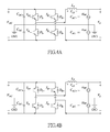
- FIG. 4A shows a perspective diagram of a single-phase three-wire inverter operating during a positive half-cycle in an grid-connection mode according to an embodiment of the instant disclosure
- FIG. 4B shows a perspective diagram of a single-phase three-wire inverter operating during a negative half-cycle in an grid-connection mode according to an embodiment of the instant disclosure
- FIG. 5 shows a waveform of triangular wave for a symmetrical carrier according to an embodiment of the instant disclosure
- FIG. 6 shows a control block diagram of a single-phase three-wire inverter operating in an grid-connection mode and a rectification mode according to an embodiment of the instant disclosure
- FIG. 7A shows a waveform diagram of an alternating current and a corresponding voltage without considering the inductor variance conventionally
- FIG. 7B shows a waveform diagram of an alternating current and a corresponding voltage of a single-phase three-wire power control system according to an embodiment of the instant disclosure
- FIG. 8A shows a perspective diagram of a single-phase three-wire inverter operating during a positive half-cycle in a voltage-control mode according to an embodiment of the instant disclosure
- FIG. 8B shows a perspective diagram of a single-phase three-wire inverter operating during a negative half-cycle in a voltage-control mode according to an embodiment of the instant disclosure
- FIG. 9A shows a circuit diagram of an equivalent circuit of a load according to an embodiment of the instant disclosure.
- FIG. 9B shows a circuit diagram of an equivalent circuit of another load according to an embodiment of the instant disclosure.
- FIG. 10 shows a control block diagram of a single-phase three-wire inverter operating in a voltage-control mode according to an embodiment of the instant disclosure
- FIG. 11 shows a waveform diagram of an output voltage and an output current when a single-phase three-wire inverter depicted in FIG. 10 operating in a voltage-control mode is applied to a resistive load;
- FIG. 12 shows a waveform diagram of an output voltage and an output current when a single-phase three-wire inverter depicted in FIG. 10 operating in a voltage-control mode is applied to a capacitive load;
- FIG. 13 shows a waveform diagram of an output voltage and an output current when a single-phase three-wire inverter depicted in FIG. 10 operating in a voltage-control mode is applied to an inductive load;
- FIG. 14 shows a flow chart of a power control method according to an embodiment of the instant disclosure.
- a single-phase three-wire inverter in this embodiment can be a connection for regulating power between a DC power (e.g. a DC power supply device 2 in FIG. 2A ) and an AC power (e.g. an AC power source 4 in FIG. 2A ), such as a single-phase three-wire emergency power system 1 shown in FIG. 2A , FIG. 2B and FIG. 2C .
- the inverter in this embodiment may include a bi-directional inverter.
- the single-phase three-wire inverter disclosed in this embodiment can be operated in three modes comprising a grid-connection mode, a rectification mode and a voltage-control mode.
- the single-phase three-wire inverter can be an emergency power source connected to the utility grid.
- the utility grid i.e. power grid
- an AC load 3 is powered by the utility grid 4 .
- the grid-connection mode may be started, in which the power flow PFa represents that the DC power supply device 2 provides energy to the AC end as shown in FIG. 2A .
- the power flow PFb represents that the utility grid 4 provides energy to the DC power supply device 2 as shown in FIG. 2B .
- the single-phase three-wire inverter goes to the voltage-control mode, meanwhile the system can function as an uninterruptible power supply (UPS), in which the power flow FPc represents that the DC power supply device 2 provides energy to the AC load 3 as shown in FIG. 3 .
- UPS uninterruptible power supply
- FIG. 3 shows a circuit block diagram of the single-phase three-wire emergency power system according to an embodiment of the instant disclosure.
- the power control system for the single-phase three-wire inverter i.e. the single-phase three-wire emergency power system 1
- the AC power source 4 is utility grid.
- the single-phase three-wire power control system comprises a single-phase three-wire inverter 14 , a driving unit 15 , a sampling unit 16 and a processing unit 17 .
- the single-phase three-wire inverter 14 is coupled between the DC power supply device 2 and the AC power source 4 for converting a DC voltage V DC of the DC power supply device 2 to an output voltage V S .
- the single-phase three-wire inverter 14 has a first half-bridge DC-AC power converter and a second half-bridge DC-AC power converter parallel-coupled to each other.
- the first half-bridge DC-AC power converter is constituted of a power switch S A+ , a power switch S A ⁇ and the inductor L S1 connected to the first power line 11 .
- the second half-bridge DC-AC power converter is constituted of a power switch SB+, a power switch S B ⁇ and an inductor L S2 connected to the second power line 12 .
- the power switch S A+ and the power switch S A ⁇ of the first half-bridge DC-AC power converter are coupled to the first power line 11 through the inductor L S1 .
- the power switch S B+ and the power switch S B ⁇ of the second half-bridge DC-AC power converter are coupled to the second power line 12 .
- Each of the power switches S A+ , S A ⁇ , S B+ and S B ⁇ is respectively parallel-connected to an inverted diode D A+ , D A ⁇ , D B+ and D B ⁇ .
- this inverter has three arms, in which a first arm comprises the power switches S A ⁇ and S A ⁇ connected in series, a second arm comprises the power switches S B and S B ⁇ connected in series, and a third arm comprises capacitors C DC+ and C DC ⁇ connected in series. Switching of the third arm is utilized to compensate the unbalance of the load, wherein the first power line 11 and the third power line 13 represent an AC voltage, and the second power line 12 and the third power line 13 represent another AC voltage, thus the aforementioned two AC voltages can keep balanced when the power outage of utility grid is occurred. However, the current on the third power line 13 (also called the neutral line) is zero when the utility grid is normal.
- the driving unit 15 is coupled to the power switches S A ⁇ , S A ⁇ , S B+ and S B ⁇ of the single-phase three-wire inverter 14 .
- the sampling unit 16 is coupled to the inductors L S1 and L S2 for sampling inductor currents of the inductors L S1 and L S2 .
- the processing unit 17 is coupled to the driving unit 15 and the sampling unit 16 .
- the processing unit 17 controls the power switches S A+ , S A ⁇ , S B+ and S B ⁇ of the single-phase three-wire inverter 14 through the driving unit 15 .
- the inductors L S1 and L S2 can be equivalent to an inductor L S shown in FIG. 4A .
- the processing unit 17 obtains a duty ratio D(n+1) of a next cycle according to the inductance of the inductor L S , the total variation ⁇ I LS of the inductor current, the DC voltage V DC and the output voltage V S .
- the processing unit 17 obtains a current variation ⁇ i L1 of exciting the inductor and a current variation ⁇ i L2 of demagnetizing the inductor according to the DC voltage V DC , the output voltage V S , the inductance of the inductor L S of the present cycle and a duty ratio D(n) of the present cycle, and obtains the total variation ⁇ i LS of the inductor current in the present cycle according to the current variation ⁇ i L1 of exciting the inductor and the current variation ⁇ i L2 of the demagnetized inductor in the present cycle. Please refer to the following descriptions for details of the control method.
- the DC power supply device 2 of this embodiment may be a solar power generating device, a wind power generating device or other renewable power generating devices, in order to generate a small scale DC voltage V DC .
- the AC power source 4 may be a general household electricity system which is mainly for providing a single-phase AC voltage V S .
- circuit element such as capacitances C AC+ and C AC ⁇ may be added for amending the non-ideal circuit characteristics when the inductors L S1 , L S2 and the AC power source 4 are coupled practically.
- the manner of the driving unit 15 controlling the power switches S A+ , S A ⁇ , S B+ and S B ⁇ is making the power switches S A+ , S A ⁇ , S B ⁇ and S B ⁇ of the first half-bridge DC-AC power converter and the second half-bridge DC-AC power converter be both bipolarized switched.
- FIG. 4A shows a perspective diagram of the single-phase three-wire inverter operating during a positive half-cycle in a grid-connection mode according to an embodiment of the instant disclosure.
- one switching cycle can be divided into two sections which are a section of exciting the inductor and a section of demagnetizing the inductor.
- the equation (3) in the following can be obtained.
- the total variation of the inductor current in the present cycle is the current variation of exciting the inductor added with the current variation of the demagnetized inductor.
- ⁇ i LS ⁇ i L1 + ⁇ i L2 (3)
- inductor's current variation ⁇ i LS is equal to a reference current minus a feedback current, thus the current variation can be obtained, wherein the current variation in the equation (3) including a feedforward component (I ref (n+1) ⁇ I ref (n)) in a cycle and an error component (I ref (n) ⁇ I fb (n)), which can be characterized by equation (6).
- ⁇ i LS [i ref ( n+ 1) ⁇ i ref ( n )]+ K P [i ref ( n ) ⁇ i fb ( n )] (6)
- the processing unit 17 utilizes the current feedforward control and according to the reference current (comprising the reference current I ref (n+1) of the next cycle and the reference current I ref (n) of the present cycle) and the feedback current I fb (n) of the present cycle to obtain the inductor's total current variation ⁇ i LS , wherein the feedback current is the inductor current multiplied with a ratio factor H.
- the control block for the grid-connection mode and the rectification mode is shown in FIG. 6 . Then, please refer to following description about the rectification mode.
- the rectification mode can have the function of power factor correction.
- the derivation of the control low of the rectification mode is the same as that of the grid-connection mode, referring to following equation (8) and equation (9).
- the total variation of the inductor current in the present cycle is the current variation of exciting the inductor added with the current variation of the demagnetized inductor.
- equation (11) can be rewritten as equation (12).
- r L is the resistance of the inductor L
- H represents the scale factor
- the chip of the processing unit is selected to operate a triangular wave mode with a symmetrical carrier, the output duty ratio of pulse width modulation will have a symmetrical distribution about a central point (i.e. the peak) of the triangular wave, then the average of the inductor current within the cycle can be equal to the reference current.
- Curve “a” is a built-in triangular wave of the processing unit, and curve “b” is an inductor current I L . Therefore, when sampling the feedback current at the central point (which is the peak) of the triangular wave (of the curve “a”), the feedback current will be accurately match with the reference current, and it only needs sampling once. Additionally, in the triangular wave mode, sampling at the central point may make the sampling point avoid the switching noise occurred when turning-on and turning-off of the switches.
- FIG. 6 shows a control block diagram of a single-phase three-wire inverter operating in an grid-connection mode and a rectification mode according to an embodiment of the instant disclosure. Firstly, utilizing a subtractor 61 to subtract the reference current I ref (n) of the present duty cycle from the reference current I ref (n+1) of the next duty cycle to obtain a feedforward component (I ref (n+1) ⁇ I ref (n)).
- an adder 67 outcomes the duty ratio D(n+1) of the single-phase three-wire inverter 14 in the next duty cycle, as characterized by equation (5) or (11), wherein equation (5) and equation (11) are respectively adapted to the grid-connection mode and the rectification mode. Then, utilizing a transfer function G P of a multiplexer 68 to obtain the inductor's current i L (n+1) of the single-phase three-wire inverter 14 in the next duty cycle according to the duty ratio D(n+1).
- this invention provides a control scheme which allows the inductance variation for controlling the single-phase three-wire inverter.
- This embodiment introduces the inductance variation into the control scheme.
- the control scheme takes into account the inductance variances, large variation of inductance would be allowed, and the speed response and system stability will be improved, meanwhile overdesign for the inductor will be avoided in order to reduce the volume of the inductor and related cost.
- FIG. 7A and FIG. 7B FIG.
- FIG. 7A shows a waveform diagram of an alternating current and a corresponding voltage without considering the inductor variance conventionally
- FIG. 7B shows a waveform diagram of an alternating current and a corresponding voltage of a single-phase three-wire power control system according to an embodiment of the instant disclosure.
- FIG. 8A shows a perspective diagram of a single-phase three-wire inverter operating during a positive half-cycle in a voltage-control mode according to an embodiment of the instant disclosure
- FIG. 8B shows a perspective diagram of a single-phase three-wire inverter operating during a negative half-cycle in a voltage-control mode according to an embodiment of the instant disclosure.
- the processor 17 utilizes load impedance estimation and iterative learning control to compensate the output voltage V S except for considering the conditions of exciting the inductor and demagnetizing the inductor.
- the DC link provides power to the load through the single-phase three-wire inverter 14 , meanwhile a relay on the neutral line (the third power line 13 ) is in cooperated, and the load is presented by loads 81 , 82 shown in FIG. 8A (and FIG. 8B ). As shown in FIG.
- the duty ratio of the power switch S A+ and the power switch S B ⁇ is the duty ratio D
- the duty ratio of the power switch S A ⁇ and the power switch S B+ is the complementary (1-D) of the duty ratio D
- the power switch S A ⁇ and the power switch S B+ are cutoff, which causes the inductor L S to be excited, then the voltage drop V LS across the inductor L S is equal to V DC ⁇ V S .
- equation (13) and equation (14) can be taken into equation (3) to obtain equation (15), wherein T is a switching period, L S is an inductance.
- the load can be presented by a resistor R′, an inductor L′ and a capacitor C′ connected in series, and can be equivalent to a load resistor R, a load inductor L and a load capacitor C connected in parallel, such thatthe load can be the RLC load parallelly connected with a rectification load.
- load comprises a nonlinear load
- the current variation generated by the load of the next cycle could be characterized by equation (17).
- ⁇ i ( n+ 1) ⁇ i R + ⁇ i C + ⁇ i L (17)
- the current variation ⁇ i(n+1) generated by the load of the next cycle is the summation of the following three current variations due to three types of loads, ⁇ i R , ⁇ i L , ⁇ i C , wherein ⁇ i R is the current variation passing the resistive load which can be derived in the following:
- ⁇ i L is the current variation passing through the capacitive load and can be derived in the following:
- i L ⁇ ( n + 1 ) i L ⁇ ( n + 1 ) - i L ⁇ ( n ) ⁇ ⁇
- v(n+3/2), v(n+1/2) and v(n ⁇ 1/2) which can be calculated in the following:
- v ⁇ ( n + 3 2 ) v ⁇ ( n + 2 ) + v ⁇ ( n + 1 ) 2 ( 25 )
- v ⁇ ( n + 1 2 ) v ⁇ ( n + 1 ) + v ⁇ ( n ) 2 ( 26 )
- v ⁇ ( n - 1 2 ) v ⁇ ( n ) + v ⁇ ( n - 1 ) 2 ( 27 )
- i C ⁇ ( n + 1 ) C ⁇ ⁇ ⁇ ⁇ v ⁇ ( n + 1 ) T ( 30 )
- i C ⁇ ( n ) C ⁇ ⁇ ⁇ ⁇ v ⁇ ( n ) T ( 31 )
- equations (19), (23) and (32) can be taken into equation (17), and equation (33) can be obtained after rearrangement:
- ⁇ ⁇ ⁇ i ( • ) ⁇ ( n + 1 ) V ref ⁇ ( n + 1 ) - V fb ⁇ ( n ) R + C ⁇ [ V ref ⁇ ( n + 2 ) - V ref ⁇ ( n + 1 ) ] - [ V fb ⁇ ( n ) - V fb ⁇ ( n - 1 ) ] 2 ⁇ T + V ref ⁇ ( n + 1 ) + V fb ⁇ ( n ) 2 ⁇ L ⁇ T ( 33 )
- d i ⁇ ( n + 1 ) k p ⁇ ⁇ 2 ⁇ ⁇ ( n + 1 ) ⁇ ⁇ L S ⁇ ( n + 1 ) L max ⁇ [ v ref ⁇ ( n + 1 ) - v fb ′ ⁇ ( n + 1 ) ] ⁇ ( 37 )
- V ref is the reference voltage built by the system
- V′ fb is the feedback voltage of the previous cycle (of the utility grid)
- the control gain k p2 can be characterized by equation (38).
- k p2 ( n+ 1) k′ p2 ( n+ 1)+ k p0 [v ref ( n+ 1) ⁇ v′ fb ( n+ 1)] (38)
- k′ p2 is the control gain of the previous cycle of utility grid (corresponding to the switching cycle)
- k p2 is the reaction result according to the gain of the previous cycle and the error component
- k p0 is the preset initial gain. While introducing the iterative learning control, the error of output voltage of the system in a steady state and the total harmonic distortion can be reduced, and the control block is depicted in FIG. 10 , wherein the duty ratio of the next cycle is
- control block shown in FIG. 10 is also implemented by the processing unit 17 as detailed below.
- the control block comprises a sub-block 10 b for load impedance estimation and a sub-block 10 a for iterative learning.
- a multiplexer 112 multiplies the feedforward component e(n) with 1/R to obtain the current variation of the resistive load, as shown in equation (19).
- an adder 113 subtracts the reference current I ref (n+1) of the next cycle and the feedback current I fb (n) of the present cycle from the reference current I ref (n+2) of the next two cycle, and adding the feedback current I fb (n ⁇ 1) of the previous cycle, then utilizing a multiplexer 114 to multiplies the outcome of the adder 113 with C/2T, as shown in equation (32).
- an adder 115 subtracts the feedback current I fb (n) of the present cycle from the reference current I ref (n+1) of the next cycle, then utilizing a multiplier 116 to multiplies the outcome of the adder 115 with T/2L.
- an adder 117 adds the outcomes of the multipliers 112 , 114 and 116 to obtain the total current variation ⁇ i (•) (n+1) due to the load in the next cycle, as depicted in equation (33). Then the total current variation ⁇ i (•) (n+1) can be multiplied by a coefficient G C to obtain the variation d e (n+1) of the duty ratio estimated from the load.
- an adder 121 subtrates the reference reference voltage V ref (n+1) of the next cycle from the feedback V′ fb (n+1) of the next cycle, and utilizing multipliers 122 , 123 , 125 and 126 and an adder 124 to obtain the variation d i (n+1) of the duty ratio for iterative learning.
- An adder 131 addes the variation d e (n+1) of the duty ratio estimated from the load, the variation d e (n+1) of the duty ratio for iterative learning and the duty ratio D(n+1) of the next cycle, then the single-phase three-wire inverter 14 operates according to the duty cycle d(n+1) to obtain an AC voltage v O (n+1) of the next cycle which is converted through a transfer function G p of a multiplier 132 .
- the processing unit 17 when the single-phase three-wire power control system operates in the voltage-control mode, the processing unit 17 not only calculates the total current variation of the inductor to obtain the duty ratio D(n+1) according to the inductor's variation, the processing unit 17 also utilizes the reference voltage V ref and the feedback voltage V fb to obtain the total current variation ⁇ i (•) due to the load so as to obtain the variatoin d e (n+1) of the duty ratio estimated from the load, in which the load is equivalent to the resistive load R, the inductive load L and the capacitive load C connected in parallel and the total current variation ⁇ i (•) due to the load is the summation of the current variation of the resistive load, the current variation of the resistive load and the current variation of the capacitive load depicted in equation (33).
- the processing unit 17 also calculates the variatoin d i (n+1) of the duty ratio for iterative learning
- the processing unit 17 adds the duty ratio D(n+1), the variation d e (n+1) of the duty ratio estimated from the load and the variation d i (n+1) of the duty ratio for iterative learning to control the outputted AC voltage v O (n+1).
- FIG. 11 showing a waveform diagram of an output voltage and an output current when a single-phase three-wire inverter depicted in FIG. 10 operating in a voltage-control mode with total power of 1.1 kW is applied to a resistive load.
- the output voltages are V AN and V NB , wherein the voltage V AN is the voltage across the first power line 11 and the third power line 13 , and the voltage V NB is the voltage across the third power line 13 and the second power line 12 .
- the current i AN is the current flowing through the load connected between the first power line 11 and the third power line 13 .
- the current i NB is the current flowing through the load connected between the third power line 13 and the second power line 12 .
- the total harmonic distortions are 2.458%, 2.946% and 3.321% while utilizing control block shown in FIG. 10 to operate the single-phase three-wire inverter in 1.1 kW, 2.2 kW and 3.3 kW respectively.
- the specification requirement of total harmonic distortion for the uninterruptible power supply (UPS) is below 5%, in general, the total harmonic distortion of the conventional circuit is about 4%.
- the single-phase three-wire inverter of this embodiment can obtain lower total harmonic distortion.
- FIG. 12 showing a waveform diagram of an output voltage and an output current when a single-phase three-wire inverter depicted in FIG. 10 operating in a voltage-control mode with total power of 1.02 kVA is applied to a capacitive load.
- the total harmonic distortions are 2.590%, 2.955% and 3.305% while utilizing control block shown in FIG. 10 to operate the single-phase three-wire inverter in 1.02 kVA, 1.88 kVA and 2.86 kVA respectively.
- the total harmonic distortion of the conventional circuit is about 4%.
- the single-phase three-wire inverter of this embodiment can obtain lower total harmonic distortion.
- FIG. 13 showing a waveform diagram of an output voltage and an output current when a single-phase three-wire inverter depicted in FIG. 10 operating in a voltage-control mode with total power of 1.04 kVA is applied to an inductive load.
- the total harmonic distortions are 2.375%, 2.949% and 3.268% while utilizing control block shown in FIG. 10 to operate the single-phase three-wire inverter in 1.04 kVA, 1.81 kVA and 2.72 kVA respectively.
- the total harmonic distortion of the conventional circuit is about 4%.
- the single-phase three-wire inverter of this embodiment can obtain lower total harmonic distortion.
- FIG. 14 shows a flow chart of a power control method according to an embodiment of the instant disclosure.
- the power control method for controlling the single-phase three-wire power control system (which is the single-phase three-wire emergency power system 1 ) shown in FIG. 3 .
- the single-phase three-wire power control system has the single-phase three-wire inverter 14 .
- the single-phase three-wire inverter 14 is coupled between the DC power supply device 2 and the AC power source 4 (shown in FIG.
- the single-phase three-wire inverter 14 has a first half-bridge DC-AC power converter and a second half-bridge DC-AC power converter parallel-coupled to each other. Details of the circuit can be referred to the previous embodiment.
- the power control method comprises following steps.
- step S 110 obtaining the duty ratio D(n+1) of the next cycle according to the inductance L S of the inductor, the total variation ⁇ i LS of the inductor current, the DC voltage V DC and the output voltage V S .
- the step S 110 may comprise determining the single-phase three-wire inverter to operate in the grid-connection mode, the rectification mode or the voltage-control mode. Implementation of determining the mode switching of the single-phase three-wire inverter may be achieved in a variety of ways. The user may configure the mechanism of the mode switching arbitrarily as needed.
- the user may manually control the operation mode, or utilize a sensor to the sense the voltage and current of the AC power source to be the basis for auto-switching of the operation mode, and an artisan of ordinary skill in the art will easily appreciate the implementation manner of the mode switching, thus there is no need to go into details.
- step S 120 obtaining a current variation ⁇ i L1 of exciting the inductor and a current variation ⁇ i L2 of demagnetizing the inductor according to the DC voltage V DC , the output voltage V S , the inductance L S of the inductor in the present cycle and the duty ratio D(n) of the present cycle.
- step S 130 obtaining the total variation ⁇ I LS of the inductor current in the present cycle according to the current variation ⁇ I L1 of exciting the inductor and the current variation ⁇ I L2 of demagnetizing the inductor in the present cycle.
- the step S 110 utilizes equation (5) to calculate the duty ratio D(n+1) of the next cycle.
- the step S 110 utilizes equation (11) to calculate the duty ratio D(n+1) of the next cycle.
- the step S 110 obtaining the total current variation ⁇ i(•) of the load according to a reference voltage V ref and a feedback voltage V fb , equalizing the load as a resistive load R, a inductive load L and a capacitive load C connected in parallel, wherein the total current variation ⁇ i(•) of the load is the summation of the current variation of the resistive load R, the current variation of the inductive load L and the current variation of the capacitive load C as indicated in equation (33), then calculating the variation d e (n+1) of the duty ratio estimated from the load according to the total current variation ⁇ i(•) of the load.
- the offered single-phase three-wire power control system and control method introduce the variation of inductor into the control mechanism for effectively reducing the current oscillation and the current ripple as well as increasing the accuracy current tracking.
- the control mechanism only needs one sampling to obtain the average of the feedback current, the processing time of the processing unit (e.g. a single-chip) can be reduced, and the switching noise occurred when turning-on and turning-off of the switches can be avoided.
- the single-phase three-wire power control system can switch operation modes comprising the grid-connection mode and the rectification mode according to the status of the AC power source. Further, the system can operates in the voltage-control mode when the AC power source (e.g. utility grid) fails, in which the single-phase three-wire power control system further utilizes the load impedance estimation and iterative learning control to compensate the output AC voltage.
- the single-phase three-wire power control system of the mentioned embodiment introduces dead-beat control while utilizing real-time voltage sampling and current sampling to dynamically estimate the impedance of the load, and further integrates the iterative learning control to update the upper-limit and the lower-limit of the impedance for preciously tracking the reference voltage and reducing the voltage distortions.
- the mentioned control mechanism achieves cycle by cycle control for increasing the response speed, thus good power quality can be obtained even if the load is varying.
- the inductance of the inductor can be minimized and optimized by introducing the variation of the inductance into the control mechanism, in order to avoid using excessive large inductance which increases unnecessary cost.
- the control method only needs one sampling to obtain the average of the feedback current, the processing time of the single-chip can be reduced, and the switching noise occurred when turning-on and turning-off of the switches can be avoided.
Abstract
Description
Δi LS =Δi L1 +Δi L2 (3)
Δi LS =[i ref(n+1)−i ref(n)]+K P [i ref(n)−i fb(n)] (6)
Δi(n+1)=Δi R +Δi C +Δi L (17)
Δi C(n+1)=i C(n+1)−i C(n) (24)
Δv(n+1)=v(n+3/2)−v(n+1/2) (28)
Δv(n)=v(n+1/2)−v(n−1/2) (29)
k p2(n+1)=k′ p2(n+1)+k p0 [v ref(n+1)−v′ fb(n+1)] (38)
Claims (10)
k p2(n+1)=k′ p2(n+1)+k p0 [v ref(n+1)−v′ fb(n+1)];
k p2(n+1)=k′ p2(n+1)+k p0 [v ref(n+1)−v′ fb(n+1)];
Applications Claiming Priority (3)
| Application Number | Priority Date | Filing Date | Title |
|---|---|---|---|
| TW103102292A TWI496409B (en) | 2014-01-22 | 2014-01-22 | Single-phase three-wire power control system and power control method therefor |
| TW103102292 | 2014-01-22 | ||
| TW103102292A | 2014-01-22 |
Publications (2)
| Publication Number | Publication Date |
|---|---|
| US20150207433A1 US20150207433A1 (en) | 2015-07-23 |
| US9413270B2 true US9413270B2 (en) | 2016-08-09 |
Family
ID=53545700
Family Applications (1)
| Application Number | Title | Priority Date | Filing Date |
|---|---|---|---|
| US14/596,730 Active 2035-02-25 US9413270B2 (en) | 2014-01-22 | 2015-01-14 | Single-phase three-wire power control system and power control method therefor |
Country Status (2)
| Country | Link |
|---|---|
| US (1) | US9413270B2 (en) |
| TW (1) | TWI496409B (en) |
Cited By (6)
| Publication number | Priority date | Publication date | Assignee | Title |
|---|---|---|---|---|
| US20160315556A1 (en) * | 2015-04-27 | 2016-10-27 | Abb Technology Ag | Method for acquiring values indicative of an ac current of an inverter and related circuit and inverter |
| US20170047729A1 (en) * | 2014-04-29 | 2017-02-16 | Nr Electric Co., Ltd. | Relay protection method and apparatus against lc parallel circuit detuning faults |
| US10148222B2 (en) | 2015-09-24 | 2018-12-04 | Delta Electronics, Inc. | Inverter apparatus and solar energy grid-connected power generation system |
| TWI723491B (en) * | 2019-08-14 | 2021-04-01 | 台達電子工業股份有限公司 | Bidirectional power factor correction module |
| TWI748347B (en) * | 2020-02-15 | 2021-12-01 | 國立清華大學 | Control method for single-phase inverter and device thereof |
| US11539292B2 (en) * | 2018-02-16 | 2022-12-27 | Mitsubishi Electric Corporation | Power converter control device with feedforward |
Families Citing this family (4)
| Publication number | Priority date | Publication date | Assignee | Title |
|---|---|---|---|---|
| CN105940353B (en) * | 2014-01-30 | 2019-01-04 | 株式会社明电舍 | Periodical external disturbance inhibits control device |
| CN105496549A (en) * | 2015-10-29 | 2016-04-20 | 绵阳立德电子股份有限公司 | RF (radio frequency) generator and method for generating RF energy by using same |
| TWI606679B (en) * | 2017-01-23 | 2017-11-21 | Acbel Polytech Inc | Totem pole power factor corrector and its current detection unit |
| TWI746097B (en) * | 2020-07-31 | 2021-11-11 | 台達電子工業股份有限公司 | Power conversion device with dual-mode control |
Citations (12)
| Publication number | Priority date | Publication date | Assignee | Title |
|---|---|---|---|---|
| US6282111B1 (en) * | 1999-06-18 | 2001-08-28 | Avionic Instruments Inc | Inverter control using current mode slope modulation |
| US6337801B2 (en) * | 1999-12-16 | 2002-01-08 | Virginia Tech Intellectual Properties, Inc. | Three-phase zero-current-transition (ZCT) inverters and rectifiers with three auxiliary switches |
| US20070109822A1 (en) * | 2005-11-14 | 2007-05-17 | Kan-Sheng Kuan | Zero voltage switch method for synchronous rectifier and inverter |
| US20070211507A1 (en) * | 2006-03-03 | 2007-09-13 | Milan Ilic | Interleaved soft switching bridge power converter |
| US20080013351A1 (en) * | 2006-06-06 | 2008-01-17 | Ideal Power Converters, Inc. | Universal Power Converter |
| US7336513B1 (en) * | 2006-09-12 | 2008-02-26 | National Chung Cheng University | Method of compensating output voltage distortion of half-bridge inverter and device based on the method |
| US20100097827A1 (en) * | 2007-07-02 | 2010-04-22 | Ben-Gurion University Of The Negev Research And Development Aurthority | Method And Circuitry for Improving the Magnitude and Shape of the Output Current of Switching Power Converters |
| US20120014138A1 (en) * | 2010-07-16 | 2012-01-19 | Khai Doan The Ngo | Pulse width modulated resonant power conversion |
| US20120014151A1 (en) * | 2009-08-17 | 2012-01-19 | Ideal Power Converters, Inc. | Power Conversion with Added Pseudo-Phase |
| US20120153729A1 (en) * | 2010-12-17 | 2012-06-21 | Korea Institute Of Energy Research | Multi-input bidirectional dc-dc converter |
| US20120176090A1 (en) * | 2008-09-11 | 2012-07-12 | Eetrex Incorporated | Bi-directional inverter-charger |
| US20130057200A1 (en) * | 2011-06-22 | 2013-03-07 | Eetrex, Incorporated | Bidirectional inverter-charger |
Family Cites Families (2)
| Publication number | Priority date | Publication date | Assignee | Title |
|---|---|---|---|---|
| JP5270681B2 (en) * | 2008-09-18 | 2013-08-21 | 株式会社三社電機製作所 | Inverter for grid connection |
| TWI453986B (en) * | 2011-05-18 | 2014-09-21 | Nat Univ Tainan | Fuel cell controll system |
-
2014
- 2014-01-22 TW TW103102292A patent/TWI496409B/en active
-
2015
- 2015-01-14 US US14/596,730 patent/US9413270B2/en active Active
Patent Citations (12)
| Publication number | Priority date | Publication date | Assignee | Title |
|---|---|---|---|---|
| US6282111B1 (en) * | 1999-06-18 | 2001-08-28 | Avionic Instruments Inc | Inverter control using current mode slope modulation |
| US6337801B2 (en) * | 1999-12-16 | 2002-01-08 | Virginia Tech Intellectual Properties, Inc. | Three-phase zero-current-transition (ZCT) inverters and rectifiers with three auxiliary switches |
| US20070109822A1 (en) * | 2005-11-14 | 2007-05-17 | Kan-Sheng Kuan | Zero voltage switch method for synchronous rectifier and inverter |
| US20070211507A1 (en) * | 2006-03-03 | 2007-09-13 | Milan Ilic | Interleaved soft switching bridge power converter |
| US20080013351A1 (en) * | 2006-06-06 | 2008-01-17 | Ideal Power Converters, Inc. | Universal Power Converter |
| US7336513B1 (en) * | 2006-09-12 | 2008-02-26 | National Chung Cheng University | Method of compensating output voltage distortion of half-bridge inverter and device based on the method |
| US20100097827A1 (en) * | 2007-07-02 | 2010-04-22 | Ben-Gurion University Of The Negev Research And Development Aurthority | Method And Circuitry for Improving the Magnitude and Shape of the Output Current of Switching Power Converters |
| US20120176090A1 (en) * | 2008-09-11 | 2012-07-12 | Eetrex Incorporated | Bi-directional inverter-charger |
| US20120014151A1 (en) * | 2009-08-17 | 2012-01-19 | Ideal Power Converters, Inc. | Power Conversion with Added Pseudo-Phase |
| US20120014138A1 (en) * | 2010-07-16 | 2012-01-19 | Khai Doan The Ngo | Pulse width modulated resonant power conversion |
| US20120153729A1 (en) * | 2010-12-17 | 2012-06-21 | Korea Institute Of Energy Research | Multi-input bidirectional dc-dc converter |
| US20130057200A1 (en) * | 2011-06-22 | 2013-03-07 | Eetrex, Incorporated | Bidirectional inverter-charger |
Cited By (8)
| Publication number | Priority date | Publication date | Assignee | Title |
|---|---|---|---|---|
| US20170047729A1 (en) * | 2014-04-29 | 2017-02-16 | Nr Electric Co., Ltd. | Relay protection method and apparatus against lc parallel circuit detuning faults |
| US10128650B2 (en) * | 2014-04-29 | 2018-11-13 | Nr Electric Co., Ltd. | Relay protection method and apparatus against LC parallel circuit detuning faults |
| US20160315556A1 (en) * | 2015-04-27 | 2016-10-27 | Abb Technology Ag | Method for acquiring values indicative of an ac current of an inverter and related circuit and inverter |
| US9712082B2 (en) * | 2015-04-27 | 2017-07-18 | Abb Schweiz Ag | Method for acquiring values indicative of an AC current of an inverter and related circuit and inverter |
| US10148222B2 (en) | 2015-09-24 | 2018-12-04 | Delta Electronics, Inc. | Inverter apparatus and solar energy grid-connected power generation system |
| US11539292B2 (en) * | 2018-02-16 | 2022-12-27 | Mitsubishi Electric Corporation | Power converter control device with feedforward |
| TWI723491B (en) * | 2019-08-14 | 2021-04-01 | 台達電子工業股份有限公司 | Bidirectional power factor correction module |
| TWI748347B (en) * | 2020-02-15 | 2021-12-01 | 國立清華大學 | Control method for single-phase inverter and device thereof |
Also Published As
| Publication number | Publication date |
|---|---|
| US20150207433A1 (en) | 2015-07-23 |
| TW201531010A (en) | 2015-08-01 |
| TWI496409B (en) | 2015-08-11 |
Similar Documents
| Publication | Publication Date | Title |
|---|---|---|
| US9413270B2 (en) | Single-phase three-wire power control system and power control method therefor | |
| US9450436B2 (en) | Active power factor corrector circuit | |
| US20120300515A1 (en) | AC/DC Converter with a PFC and a DC/DC Converter | |
| US20050275976A1 (en) | Power conversion apparatus and methods using an adaptive waveform reference | |
| Han et al. | Dynamic modeling and controller design of dual-mode Cuk inverter in grid-connected PV/TE applications | |
| Ghosh et al. | Generalized feedforward control of single-phase PWM rectifiers using disturbance observers | |
| WO2016125292A1 (en) | Dc-dc converter, electric power converter, electric power generation system and method for dc-dc conversion | |
| Panov et al. | Novel transformer-flux-balancing control of dual-active-bridge bidirectional converters | |
| US20190341842A1 (en) | Power factor correction circuit, control method and controller | |
| Zhang et al. | MIMO control of a high-step-up isolated bidirectional DC–DC converter | |
| CN107947585B (en) | Load feedforward control method of double full-bridge DC/DC converter | |
| Merai et al. | An improved dc-link voltage control for a three-phase PWM rectifier using an adaptive PI controller combined with load current estimation | |
| CN104685751A (en) | Controlling a voltage-adapting electronic module | |
| Anwar et al. | A simple control architecture for four-switch buck-boost converter based power factor correction rectifier | |
| Nallusamy et al. | Power quality improvement in a low‐voltage DC ceiling grid powered system | |
| CN111181420A (en) | Single-phase Vienna rectifier and control method thereof | |
| WO2019097835A1 (en) | Power conversion device | |
| Channappanavar et al. | Current sensorless Power Factor correction circuit using FPGA | |
| Kim et al. | MATLAB-based digital design of current mode control for multi-module bidirectional battery charging/discharging converters | |
| Bagawade et al. | Digital implementation of one-cycle controller (OCC) for AC-DC converters | |
| TWI436573B (en) | Method and system for controlling current | |
| Nair et al. | Implementation aspects of a single phase boost PFC converter | |
| Ganacim et al. | Output power feedforward technique applied to a high power factor rectifier with high frequency transformer | |
| CA2865612C (en) | Dc-bus controller for an inverter | |
| US11557972B2 (en) | Power conversion device |
Legal Events
| Date | Code | Title | Description |
|---|---|---|---|
| AS | Assignment |
Owner name: LITE-ON TECHNOLOGY CORPORATION, TAIWAN Free format text: ASSIGNMENT OF ASSIGNORS INTEREST;ASSIGNORS:LIU, YUNG-HSIANG;WU, TSAI-FU;CHANG, CHIH-HAO;AND OTHERS;SIGNING DATES FROM 20140116 TO 20140117;REEL/FRAME:034709/0664 Owner name: LITE-ON ELECTRONICS (GUANGZHOU) LIMITED, CHINA Free format text: ASSIGNMENT OF ASSIGNORS INTEREST;ASSIGNORS:LIU, YUNG-HSIANG;WU, TSAI-FU;CHANG, CHIH-HAO;AND OTHERS;SIGNING DATES FROM 20140116 TO 20140117;REEL/FRAME:034709/0664 |
|
| STCF | Information on status: patent grant |
Free format text: PATENTED CASE |
|
| MAFP | Maintenance fee payment |
Free format text: PAYMENT OF MAINTENANCE FEE, 4TH YEAR, LARGE ENTITY (ORIGINAL EVENT CODE: M1551); ENTITY STATUS OF PATENT OWNER: LARGE ENTITY Year of fee payment: 4 |
|
| MAFP | Maintenance fee payment |
Free format text: PAYMENT OF MAINTENANCE FEE, 8TH YEAR, LARGE ENTITY (ORIGINAL EVENT CODE: M1552); ENTITY STATUS OF PATENT OWNER: LARGE ENTITY Year of fee payment: 8 |