US9407172B2 - Vibration power generator - Google Patents
Vibration power generator Download PDFInfo
- Publication number
- US9407172B2 US9407172B2 US14/060,073 US201314060073A US9407172B2 US 9407172 B2 US9407172 B2 US 9407172B2 US 201314060073 A US201314060073 A US 201314060073A US 9407172 B2 US9407172 B2 US 9407172B2
- Authority
- US
- United States
- Prior art keywords
- electrodes
- fixed
- vibrating body
- electret
- substrate
- Prior art date
- Legal status (The legal status is an assumption and is not a legal conclusion. Google has not performed a legal analysis and makes no representation as to the accuracy of the status listed.)
- Active, expires
Links
- 239000000758 substrate Substances 0.000 claims abstract description 125
- 230000000284 resting effect Effects 0.000 claims abstract description 50
- 230000008859 change Effects 0.000 description 102
- 238000006073 displacement reaction Methods 0.000 description 86
- 238000010248 power generation Methods 0.000 description 18
- 238000009413 insulation Methods 0.000 description 16
- 125000006850 spacer group Chemical group 0.000 description 14
- 230000004907 flux Effects 0.000 description 12
- 238000000034 method Methods 0.000 description 9
- 230000007423 decrease Effects 0.000 description 7
- 239000003990 capacitor Substances 0.000 description 6
- 230000000694 effects Effects 0.000 description 6
- 230000005684 electric field Effects 0.000 description 6
- 239000011521 glass Substances 0.000 description 4
- 229910052710 silicon Inorganic materials 0.000 description 4
- 239000010703 silicon Substances 0.000 description 4
- 230000003247 decreasing effect Effects 0.000 description 3
- 230000006872 improvement Effects 0.000 description 3
- 239000000463 material Substances 0.000 description 3
- 238000010586 diagram Methods 0.000 description 2
- 230000006698 induction Effects 0.000 description 2
- 229910052751 metal Inorganic materials 0.000 description 2
- 239000002184 metal Substances 0.000 description 2
- 230000001105 regulatory effect Effects 0.000 description 2
- RYGMFSIKBFXOCR-UHFFFAOYSA-N Copper Chemical compound [Cu] RYGMFSIKBFXOCR-UHFFFAOYSA-N 0.000 description 1
- 235000016796 Euonymus japonicus Nutrition 0.000 description 1
- 240000006570 Euonymus japonicus Species 0.000 description 1
- 230000009471 action Effects 0.000 description 1
- 229910052782 aluminium Inorganic materials 0.000 description 1
- XAGFODPZIPBFFR-UHFFFAOYSA-N aluminium Chemical compound [Al] XAGFODPZIPBFFR-UHFFFAOYSA-N 0.000 description 1
- 239000004020 conductor Substances 0.000 description 1
- 229910052802 copper Inorganic materials 0.000 description 1
- 239000010949 copper Substances 0.000 description 1
- 238000003795 desorption Methods 0.000 description 1
- 239000013013 elastic material Substances 0.000 description 1
- 230000005674 electromagnetic induction Effects 0.000 description 1
- 239000000284 extract Substances 0.000 description 1
- 238000003306 harvesting Methods 0.000 description 1
- 230000004048 modification Effects 0.000 description 1
- 238000012986 modification Methods 0.000 description 1
- 150000004767 nitrides Chemical class 0.000 description 1
- 229910021420 polycrystalline silicon Inorganic materials 0.000 description 1
- 229920005591 polysilicon Polymers 0.000 description 1
- 239000011347 resin Substances 0.000 description 1
- 229920005989 resin Polymers 0.000 description 1
- 238000007789 sealing Methods 0.000 description 1
Images


Classifications
-
- H—ELECTRICITY
- H02—GENERATION; CONVERSION OR DISTRIBUTION OF ELECTRIC POWER
- H02N—ELECTRIC MACHINES NOT OTHERWISE PROVIDED FOR
- H02N1/00—Electrostatic generators or motors using a solid moving electrostatic charge carrier
- H02N1/06—Influence generators
- H02N1/08—Influence generators with conductive charge carrier, i.e. capacitor machines
Definitions
- the present invention relates to a vibration power generator that converts vibration energy into electric power.
- Electrostatic induction vibration power generators include a semi-permanently charged film called electret that is placed either on an electrode of a vibrating body or on a fixed electrode opposed to the vibrating body in a device. By changing the electrostatic capacity between the two electrodes, an electric current is induced, and the induced current generates a voltage. An electric power is thus extracted.
- FIGS. 9( a ) and 9( b ) show a conventional vibration power generator.
- FIG. 9( a ) is a cross-sectional view of the vibration power generator when its vibrating body is at a resting position.
- FIG. 9( b ) is a cross-sectional view of the vibration power generator when its vibrating body is displaced.
- an insulation film 902 is provided on a fixed substrate 901 .
- a plurality of first fixed electrodes 903 having a width 2 w and a plurality of second fixed electrodes 904 having a width 2 w are alternately placed at gaps w/10.
- a hollow spacer 905 is placed on the fixed substrate 901 .
- the spacer 905 and the vibrating body 907 are connected to each other via at least two springs 906 in such a manner that the vibrating body 907 is vibratable with respect to the spacer 905 .
- the vibrating body 907 is placed facing the fixed substrate 901 , and spaced from the fixed substrate 901 such that electret electrodes 909 formed on the vibrating body 907 are positioned at a distance w from the first fixed electrodes 903 or the second electrodes 904 formed on the fixed substrate 901 .
- the vibrating body 907 On the vibrating body 907 , the electret electrodes 909 having a width 2 w +w/10 are placed, and the vibrating body 907 and the electret electrodes 909 are sandwiching an insulation film 908 .
- the vibrating body 907 , the first fixed electrodes 903 and the second fixed electrodes 904 are arranged such that, when the vibrating body 907 is at a resting position, each overlap between the electret electrodes 909 and the first fixed electrodes 903 or the second fixed electrodes 904 has a width w in the x direction if viewed from a top-down perspective.
- a lid substrate 910 is provided on the spacer 905 to seal the vibration power generator.
- the electret electrodes 909 are injected with negative charge, and the vibrating body 907 is vibratabie in the x direction. As illustrated in FIGS. 9( a ) and 9( b ) , the highest positive charge is induced at the first fixed electrodes 903 when change of a first capacitance C 1 between the electret electrodes 909 and the first fixed electrodes 903 reaches the maximum value, and the highest positive charge is induced at the second fixed electrodes 904 when change of a second capacitance C 2 between the electret electrodes 909 and the second fixed electrodes 904 reaches the maximum value.
- the electrostatic force is weak when the vibrating body 907 is around the position of maximum displacement, which creates another problem that the vibrating body 907 may collide against a stopper and be broken.
- a vibrating body having a surface opposed to a surface of the fixed substrate, the vibrating body being vibratable with respect to the fixed substrate;
- each of the plurality of first fixed electrodes and each of the plurality of second fixed electrodes being alternately aligned in the vibration direction on the other of the surface of the fixed substrate and the surface of the vibrating body
- each of the plurality of electret electrodes overlaps with both electrodes of a corresponding fixed electrode pair if viewed from a top down perspective, the corresponding fixed electrode pair being one of the plurality of first fixed electrodes and one of the plurality of second fixed electrodes that are opposed to the one of the plurality of electret electrode, and
- each of the plurality of electret electrodes always overlaps with at least one electrode of the corresponding fixed electrode pair if viewed from a top down perspective.
- the present invention it becomes possible to provide a vibrating power generator that can generate increased electric power. It also becomes possible to provide a vibration power generator having high reliability by preventing its vibrating body from breakage.
- FIG. 1( a ) is a cross-sectional view of a vibration power generator according to an embodiment of the present invention when a vibrating body is at a resting position.
- FIG. 1( b ) is a cross-sectional view of the vibration power generator according to the embodiment of the present invention when the vibrating body is at the position of maximum displacement.
- FIGS. 2( a ) and 2( b ) are enlarged cross-sectional views of the vibration power generator according to the embodiment of the present invention when the vibrating body is at the resting position.
- FIG. 3 is a graph plotting displacement of the vibrating body versus capacitance change of the vibration power generator according to the embodiment of the present invention.
- FIG. 4 is a graph showing change of a first capacitance between electret electrodes and first fixed electrodes and change of a second capacitance between the electret electrodes and the second fixed electrodes, if the gap g is reduced to w/5 in the vibration power generator according to the embodiment of the present invention.
- FIG. 5 is a plan view of a fixed substrate 101 of the vibration power generator according to the embodiment of the present invention.
- FIGS. 6( a ) and 6( b ) are plan views of a vibrating body 107 of the vibration power generator according to the embodiment of the present invention.
- FIG. 7 is a cross-sectional view of the vibration power generator according to an embodiment of the present invention when an electret electrode is opposed to a first fixed electrode.
- FIG. 8 is a graph on the vibration power generator according to the embodiment of the present invention, showing change of the first capacitance between the electret electrodes and the first fixed electrodes and change of the second capacitance between the electret electrodes and the second fixed electrodes when the electret electrodes are opposed to the first fixed electrodes.
- FIG. 9( a ) is a cross-sectional view of a conventional vibration power generator when its vibrating body is at a resting position.
- FIG. 9( b ) is a cross-sectional view of the conventional vibration power generator when its vibrating body is displaced.
- FIG. 10 is a graph on the conventional vibration power generator, showing change of a first capacitance between electret electrodes and first fixed electrodes and change of a second capacitance between the electret electrodes and the second fixed electrodes, in accordance with displacement of the vibrating body.
- FIG. 11 is a graph on the conventional vibration power generator, showing differentials (dC/dx) of the linear capacitance change and the sinusoidal capacitance change of FIG. 10 with respect to the displacement in the x direction.
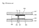
- FIG. 12 is a view for briefing a fringing field of the conventional vibration power generator.
- FIG. 13 is a view for briefing a fringing field of the vibration power generator according to the embodiment of the present invention (with a wider gap g)
- FIG. 14 is a view for briefing a fringing field of the vibration power generator according to the embodiment of the present invention (with a narrower gap g)
- a vibrating power generator including: a fixed substrate; a vibrating body vibratably placed with respect to the fixed substrate; electret electrodes aligned on the vibrating body; and first and second fixed electrodes alternately aligned on the fixed substrate. If the distance between the first fixed electrodes and the second fixed electrodes is shorter than the sum of the expansion widths of a first fringing field and a second fringing field, these expansion widths of the first fringing field and the second fringing field are both decreased by the repulsive force between them.
- the first fringing field is an electric field created by an electric flux that flows from the first fixed electrodes to the electret electrodes as expanding toward the second fixed electrodes
- the second fringing field is an electric field created by an electric flux that flows from the second fixed electrodes to the electret electrodes as expanding toward the first fixed electrodes.
- the differential value is larger than that of a straight line. This means that an electrostatic force is acting on the electret electrodes 909 , which prevents the vibrating body 907 from displacement.
- the differential value is smaller than that of a straight line (i.e. smaller than 0). This means that an electrostatic force is not acting on the vibrating body 907 very much, which may lead to breakage of the vibrating body 907 by collision of the vibrating body 907 with a stopper.
- the change of the capacitance comes close to linear change by regulating the amplitude of the electret electrodes such that when the vibrating body is at a resting position, each electret electrode overlaps with both electrodes of a corresponding fixed electrode pair if viewed from a top down perspective, the corresponding fixed electrode pair being composed of a first fixed electrode and a second electrode that are opposed to the electret electrode, and when the vibrating body is not at a resting position, each electret electrode always overlaps with at least one electrode of the corresponding fixed electrode pair.
- the electrostatic force is low enough not to prevent the movement of the vibrating body, which results in improvement of the power generation.
- Around the position of maximum displacement strong electrostatic force can prevent the vibrating body from colliding against the stopper.
- the present invention has been made based on these findings.
- FIG. 10 is a graph on the conventional vibration power generator of FIGS. 9( a ) and 9( b ) , showing change of a first capacitance between electret electrodes and first fixed electrodes and change of a second capacitance between the electret electrodes and the second fixed electrodes, in accordance with displacement of the vibrating body.
- FIG. 10 can be drawn by the boundary element method. Different from the finite element method, when the boundary element method is carried out, the inside of an object is not divided into a grid of elements, but only the electrode surface is divided into a grid of elements.
- the boundary element method is one of widely-used major general discretization methods, including the difference method and the finite element method. Regarding the capacitance between opposing parallel plates, there is no significant difference in its change profile among these methods.
- FIG. 10 shows change of the first capacitance between the electret electrodes 909 and the first fixed electrodes 903 and change of the second capacitance between the electret electrodes 909 and the second fixed electrodes 904 , when the vibrating body 907 displaces from 0 to w.
- the graph does not include the range from ⁇ w to 0 of the displacement since the first capacitance change C 1 and the second capacitance change C 2 in this range are symmetrical to those in the range from 0 to w of the displacement. Also, the graph does not include the ranges over ⁇ w of the displacement since the graph in these ranges can be analogized from the graph in the range from 0 to w of the displacement. For comparison, an example of linearly changing capacitance, i.e. linear capacitance change, and an example of sinusoidal capacitance change are plotted together.
- Each of the electrostatic force in the x direction derived from the potential difference between the electret electrodes 909 and the first fixed electrodes 903 and the electrostatic force in the x direction derived from the potential difference between the electret electrodes 909 and the second fixed electrodes 904 is proportional to the differential dC/dx of the capacitance change with respect to displacement. That is, the slope of the capacitance change is greatly related to the electrostatic force that inhibits the vibration.
- FIG. 11 shows differentials (dC/dx) of the linear capacitance change and the sinusoidal capacitance change of FIG. 10 with respect to displacement in the x direction.
- the linear change exhibits larger dC/dx than the sinusoidal change, which shows a presence of strong electrostatic force.
- the linear change exhibits smaller dC/dx than the sinusoidal change, which shows a presence of weak electrostatic force.
- a first aspect of the present invention is a vibration power generator, comprising:
- a vibrating body having a surface opposed to a surface of the fixed substrate, the vibrating body being vibratable with respect to the fixed substrate;
- each of the plurality of first fixed electrodes and each of the plurality of second fixed electrodes being alternately aligned in the vibration direction on the other of the surface of the fixed substrate and the surface of the vibrating body
- each of the plurality of electret electrodes overlaps with both electrodes of a corresponding fixed electrode pair if viewed from a top down perspective, the corresponding fixed electrode pair being one of the plurality of first fixed electrodes and one of the plurality of second fixed electrodes that are opposed to the one of the plurality of electret electrodes, and
- each of the plurality of electret electrodes always overlaps with at least one electrode of the corresponding fixed electrode pair if viewed from a top down perspective.
- a second aspect of the present invention is the vibration power generator according to the first aspect
- the plurality of electret electrodes are placed on the vibrating body, and the plurality of first fixed electrodes and the plurality of second fixed electrodes are placed on the fixed substrate.
- a third aspect of the present invention is the vibration power generator according to the first or second aspect
- a width of each of the plurality of first fixed electrodes and each of the plurality of second fixed electrodes in the vibration direction is longer than a width of overlap between each of the plurality of electret electrodes and each of the plurality of first fixed electrodes or each of the plurality of second fixed electrodes in the vibration direction if viewed from a top down perspective.
- a fourth aspect of the present invention is the vibration power generator according to any one of the first to third aspects,
- the width of each of the plurality of first fixed electrodes and each of the plurality of second fixed electrodes is longer than a sum of a width of overlap between each of the plurality of electret electrodes and each of the plurality of first fixed electrodes and a width of overlap between each of the plurality of electret electrodes and each of the plurality of second fixed electrode.
- a fifth aspect of the present invention is a vibration power generator, comprising:
- a vibrating body having a surface opposed to a surface of the fixed substrate, the vibrating body being vibratable with respect to the fixed substrate;
- each of the plurality of first fixed electrodes and each of the plurality of second fixed electrodes being alternately aligned in the vibration direction on the other of the surface of the fixed substrate and the surface of the vibrating body
- a distance (s) between each of the plurality of first fixed electrodes and each of the plurality of second fixed electrodes is not shorter than a half length of a distance (gap g) between each of the plurality of electret electrodes and each of the plurality of first fixed electrodes or each of the plurality of second fixed electrodes.
- a sixth aspect of the present invention is the vibration power generator according to the fifth aspect
- each of the plurality of electret electrodes overlaps with both electrodes of a corresponding fixed electrode pair if viewed from a top down perspective, the corresponding fixed electrode pair being one of the plurality of first fixed electrodes and one of the plurality of second fixed electrodes that are opposed to the one of the plurality of electret electrodes, and wherein when the vibrating body is not at the resting position, each of the plurality of electret electrodes always overlaps with at least one electrode of the corresponding fixed electrode pair.
- a seventh aspect of the present invention is the vibration power generator according to any one of the first to sixth aspects,
- the plurality of electret electrodes are formed into a comb shape or strips, and at least either the plurality of first fixed electrodes or the plurality of second fixed electrodes are formed into a comb shape.
- a eighth aspect of the present invention is a vibration power generator, comprising:
- a vibrating body having a surface opposed to a surface of the fixed substrate, the vibrating body being vibratable with respect to the fixed substrate;
- each of the plurality of first fixed electrodes and each of the plurality of second fixed electrodes being alternately aligned in the vibration direction on the other of the surface of the fixed substrate and the surface of the vibrating body;
- each of the plurality of electret electrodes overlaps with one of each of the plurality of first fixed electrodes and each of the plurality of second fixed electrodes and does not overlap the other of each of the plurality of first fixed electrodes and each of the plurality of second fixed electrodes if viewed from a top down perspective, and
- a width of each of the plurality of electret electrodes is longer than a width of the one of each of the plurality of first fixed electrodes and each of the plurality of second fixed electrodes.
- FIGS. 1( a ) and 1( b ) illustrate a vibration power generator according to an embodiment of the present invention.
- FIG. 1( a ) is a cross-sectional view of the vibration power generator with its vibrating body at a resting position.
- FIG. 1( b ) is a cross-sectional view of the vibration power generator with its vibrating body at the position of maximum displacement.
- FIGS. 2( a ) and 2( b ) are enlarged cross-sectional views of the vibration power generator with its vibrating body at the resting position, showing a part of the vibration power generator of FIGS. 1( a ) and 1( b ) (the vibrating body, a fixed substrate, electret electrodes, first fixed electrodes and second fixed electrodes).
- an insulation film 102 made of oxide film or the like is provided on a fixed substrate 101 made of silicon, glass or the like.
- first fixed electrodes 103 and second fixed electrodes 104 each made of polysilicon or the like having a width 2 w are alternately aligned at spacings s.
- a hollow spacer 105 made of silicon, glass, metal or the like is also provided on the insulation film 102 .
- the vibrating body 107 made of silicon, glass or the like is connected to an inner wall of the hollow spacer 105 via two springs 106 .
- the springs 106 connect the vibrating body 107 to the spacer 105 , and thus the vibrating body 107 is vibratable in the x direction.
- the vibrating body 107 is situated over the first fixed electrodes 103 and the second fixed electrodes 104 provided on the fixed substrate 101 so as to be separated from the first fixed electrodes 103 and the second fixed electrodes 104 .
- the vibrating body 107 is provided with an insulation film 108 on its surface opposed to the insulation film 102 .
- On the insulation film 108 a plurality of electret electrodes 109 made of oxide film or nitride film having a width 2 w +s are placed so as to face the first fixed electrodes 103 and the second fixed electrodes 104 at a gap g from them in the z direction.
- each overlap between the electret electrodes 109 and the first fixed electrodes 103 or the second fixed electrodes 104 has a width w in the x direction if viewed from a top down perspective.
- a face-to-face direction (z direction) designates a direction in which the electret electrodes 109 are opposed to the first fixed electrodes 103 and the second fixed electrodes 104 .
- the face-to-face direction (z direction) is perpendicular to the vibration direction (x direction).
- a lid substrate 110 made of silicon, glass or the like is provided on the spacer 105 .
- the vibrating body 107 is surrounded by the fixed substrate 101 , spacer 105 and lid substrate 110 so as to be sealed in a hermetical condition or low-vacuum condition.
- the electret electrodes 109 are injected with negative charge.
- the vibrating body 107 is vibratable in the x direction.
- the electret electrodes 109 are positioned so as to face the first fixed electrodes 103 . Accordingly, a first capacitance between the electret electrodes 109 and the first fixed electrodes 103 rises to the maximum value, and thus the highest positive charge is induced at the first fixed electrodes 103 .
- a second capacitance between the electret electrodes 109 and the second fixed electrodes 104 falls to the lowest value, and thus the lowest positive charge is induced at the second fixed electrodes 104 .
- the electret electrodes 109 are positioned so as to face the second fixed electrodes 104 . Accordingly, the second capacitance between the electret electrodes 109 and the second fixed electrodes 104 rises to the maximum value, and thus the highest positive charge is induced at the second fixed electrodes 104 .
- the first capacitance between the electret electrodes 109 and the first fixed electrodes 103 falls to the lowest value, and thus the lowest positive charge is induced at the first fixed electrodes 103 .
- Such increases and decreases of the induced charge generate a current, and thus the induced current generates a fluctuating voltage across a load 911 placed between the first fixed electrodes 103 and the second fixed electrodes 104 .
- the vibration power generator thus generates electric power.
- the vibration power generator When the vibrating body 107 is not at the resting position, the vibration power generator operates such that each electret electrode 109 always overlaps with at least one electrode of the corresponding fixed electrode pair consisting of one of the first fixed electrodes 103 and one of the second fixed electrodes 104 that are opposed to the electret electrode.
- the capacity change comes close to linear change.
- the electrostatic force is weak enough not to prevent the movement of the vibrating body, which results in improvement of the power generation.
- strong electrostatic force can prevent the vibrating body from colliding against a stopper.
- the generated alternating voltage is converted to a direct voltage by a rectifier circuit or the like, and further converted to a desired voltage by a regulator or the like.
- the resulting electric power can be stored in a capacitor or a battery, or can be directly used as a power source for a circuit.
- FIG. 3 is a graph plotting displacement of the vibrating body versus capacitance change of the vibration power generator according to the first embodiment of the present invention.
- FIG. 3 shows change of the first capacitance between the electret electrodes 109 and the first fixed electrodes 103 and change of the second capacitance between the electret electrodes 109 and the second fixed electrodes 104 , when the vibrating body 107 displaces from 0 to w in the x direction (also referred to as the vibration direction of the vibrating body 107 ).
- the first capacitance is increased and the second capacitance is decreased. They are plotted together in the single graph.
- the graph does not include the range from ⁇ w to 0 of the displacement of the vibrating body 107 since the first capacitance change C 1 and the second capacitance change C 2 in this range are symmetrical to those in the range from 0 to w of the displacement of the vibrating body 107 .
- an example of linearly changing capacitance i.e. linear capacitance change
- an example of sinusoidal capacitance change are plotted together.
- FIG. 2( a ) is an enlarged cross-sectional view of the vibration power generator according to the embodiment of the present invention, with its vibrating body 107 at the resting position.
- FIG. 2( b ) is a schematic diagram illustrating the positional relationship between the electret electrodes 109 and the first fixed electrodes 103 and/or the second fixed electrodes 104 in the following statuses: the vibrating body 107 is at the resting position; the vibrating body 107 is displaced by w; and the vibrating body 107 is displaced by more than w.
- S is a distance between the first fixed electrode 103 and the second fixed electrode 104 (i.e.
- g is a distance between the electret electrode 109 and the first fixed electrode 103 or the second fixed electrode 104 (i.e. a distance from the lower face of the electret electrode 109 to the upper face of the first fixed electrode 103 or the second fixed electrode 104 ).
- the right end of the electret electrode 109 is positioned at a distance w rightward from the left end of the first fixed electrode 103 .
- the vibrating body 107 is vibrating left and right by w about the origin (where +w (or simply written as w) is the position when the vibrating body 107 is displaced to the rightmost position, and ⁇ w is the position when the vibrating body 107 is displaced to the leftmost position).
- +w or simply written as w
- ⁇ w is the position when the vibrating body 107 is displaced to the leftmost position.
- the vibrating body 107 is vibrating right and left by w about the origin.
- the second fixed electrode 104 sticks out a distance k leftward from the electret electrode 109 .
- the vibrating body 107 is configured to shift ⁇ w from the origin.
- k is set to 0.
- FIG. 10 is a graph on the conventional vibration power generator, showing change of the first capacitance between the electret electrodes and the first fixed electrodes and change of the second capacitance between the electret electrodes and the second fixed electrodes, in accordance with displacement of the vibrating body. If the electrodes were arranged as the conventional example as shown in FIG. 10 , the gap g between the first fixed electrodes 103 or the second fixed electrodes 104 and the electret electrodes 109 would be w in the z direction, the distance s between the first fixed electrodes 103 and the second fixed electrodes 104 would be w/10, and k would be 0.
- the gap g is w
- s is set to w
- k is set to 0.
- the capacitance change with this setting is plotted in FIG. 3 , which is denoted by 301 .
- s is set to w
- k is set to 0.4 w.
- the capacitance change with this setting is denoted by 302 in FIG. 3 .
- the capacitance changes according to displacement of the vibrating body 107 gets closer to linear change in the order of the conventional example, 301 and 302 .
- the electrode arrangement of the present embodiment reduces the differential dC/dx with respect to displacement in the x direction in the range of ⁇ 0.56 w or less of the displacement of the vibrating body 107 , which decreases the electrostatic force and increases the power generation.
- the power generator since the actual displacement in ordinary use is often smaller than the maximum displacement ⁇ w, the power generator often operates within the range having weak electrostatic force, which increases the power generation efficiently.
- the maximum displacement is limited to ⁇ w by providing a stopper 112 or the like, the electrostatic force at the maximum displacement is larger than that of conventional generators, which produces an effect of reducing collision against the stopper 112 or breakage of the springs 106 .
- the fluctuation in the z direction is also small when the vibrating body 107 is vibrating in the x direction by the action of the springs 106 .
- the electrodes can keep this narrow gap and do not come in contact with each other during the vibration.
- the capacitance change in this setting is shown in FIG. 4 , where the electrode arrangement in the x direction is the same as the conventional example, i.e.
- the distance s between the first fixed electrodes 103 and the second fixed electrodes 104 is set to w/10, and k is set to 0.
- Change of the first capacitance Cc 1 between the electret electrodes 109 and the first fixed electrodes 103 and change of the second capacitance Cc 2 between the electret electrodes 109 and the second fixed electrodes 104 are both identical to linear change in the range of the displacement of the vibrating body 107 from 0 to w. As a result, this configuration also offers the effects of reducing the electrostatic force and improving the power generation.
- inter-fixed electrode distance the distance s between the first fixed electrodes 103 and the second fixed electrodes 104 (hereinafter referred to as inter-fixed electrode distance)
- the first capacitance change Cc 1 and the second capacitance change Cc 2 are both identical to linear change as illustrated in FIG. 4 , and the power generation can be improved by setting the gap g to as narrow as w/5.
- the capacitance change comes close to linear change, which makes it possible to improve the power generation. Furthermore, a braking force acts on the vibrating body 107 when the vibrating body 107 is around the position of maximum displacement, which prevents the vibrating body 107 from colliding against the stopper.
- FIG. 13 is a schematic view of the vibration power generator of FIG. 1 , illustrating only the vibrating body 107 , fixed substrate 101 , one of the electret electrodes 109 , one of the first fixed electrodes 103 , one of the second fixed electrodes 104 and insulation films 102 and 108 .
- FIGS. 12 through 14 show the electrical flux lines of only fringing fields, and the electrical flux lines of other electric fields (i.e. those in the areas surrounded by the dotted lines in FIGS. 12 and 13 , for example) are omitted.
- a vibration power generator includes: a fixed substrate 101 ; a vibrating body 107 having a surface opposed to a surface of the fixed substrate 101 , the vibrating body being vibratable with respect to the fixed substrate 101 ;
- each of the plurality of first fixed electrodes 103 and each of the plurality of second fixed electrodes 104 being alternately aligned in the vibration direction on the other of the surface of the fixed substrate 101 and the surface of the vibrating body 107 ;
- each of the plurality of electret electrodes 109 overlaps with both electrodes of a corresponding fixed electrode pair if viewed from a top down perspective, the corresponding fixed electrode pair being one of the plurality of first fixed electrodes 103 and one of the plurality of second fixed electrodes 104 that are opposed to the electret electrode 109 , and when the vibrating body 107 is not at a resting position, each of the plurality of electret electrodes always overlaps with at least one electrode of the corresponding fixed electrode pair, and
- a distance s between the first fixed electrodes 103 and the second fixed electrodes 104 is set to such a width that a first fringing field 301 and a second fringing field 302 are not largely affected by each other, where the first fringing field 301 is an electric field created by an electric flux from the first fixed electrodes 103 to the electret electrodes 109 as expanding toward the second fixed electrodes 104 and the second fringing field 302 is an electric field created by an electric flux from the second fixed electrodes 104 to the electret electrodes 109 as expanding toward the first fixed electrodes 103 .
- electric flux lines run straight in the overlapped facing areas if viewed from a top down perspective.
- curved electric flux lines run from edges of electrodes toward adjacent electrodes that are not opposed and overlapped if viewed from a top down perspective.
- the electric field created by this type of electric flux lines is called as a fringing field.
- the distance s between the first fixed electrodes 103 and the second fixed electrodes 104 is set to such a width that the first fringing field 301 and the second fringing field 302 are strongly affected by each other. Accordingly, the first fringing field 301 and the second fringing field 302 are subject to forces (repulsion forces) that push them away from each other.
- the expansion width T 1 of the first fringing field 301 and the expansion width T 2 of the second fringing field 302 are both reduced by the repulsion forces as compared to the case without repulsion force, which eventually reduces the capacitance change (i.e.
- the capacitance change is drastically decreased when the vibrating body reaches around the position of maximum amplitude. Accordingly, the capacitor change comes close to sinusoidal change, and the vibrating body becomes less movable because it is subjected to strong electrostatic force when it starts to move.
- the first fringing field 301 and the second fringing field 302 are reduced less.
- the capacitor change comes close to linear change, and the vibrating body becomes more movable because it is subjected to weak electrostatic force when it starts to move. As a result, it is possible to provide the vibration power generator with high power generation.
- the electret electrodes 109 are placed on the vibrating body 107 , and the first fixed electrodes 103 and the second fixed electrodes 104 are placed on the fixed substrate 101 .
- the first fixed electrodes 103 and the second fixed electrodes 104 are placed on the vibrating body 107 , and the electret electrodes 109 are placed on the fixed substrate 101 , wires from the load ill may interfere a vibration of the vibrating body 107 on which the first fixed electrodes 103 and the second fixed electrodes 104 are placed, since the wires are connected to the first fixed electrodes 103 and the second fixed electrodes 104 .
- the wires from the load 111 do not interfere the vibration of the vibrating body 107 , since the wires are not connected to the vibrating body 107 but to the first fixed electrodes 103 and the second fixed electrode 104 on the fixed substrate 101 .
- the vibration of the vibrating body 107 since the vibration of the vibrating body 107 is not interfered, it is possible to provide the vibration power generator with high power generation.
- the vibration power generator may be configured such that, as illustrated in FIGS. 13 , when the vibrating body 107 is at the position of maximum displacement to the fixed electrode 103 , a first length L 1 of a part of the electret electrode 109 sticking out from the first fixed electrode 103 toward the second fixed electrode 104 is set longer than the expansion width T 1 of the first fringing field 301 , and when the vibrating body 107 is at the position of maximum displacement to the second fixed electrode 104 , a second length L 2 of a part of the electret electrode 109 sticking out from the second fixed electrode 104 toward the first fixed electrode 103 is set longer than the expansion width T 2 of the second fringing field 302 .
- the first length L 1 is the length of a part of the electret electrode 109 sticking out from the first fixed electrode 103 toward the second fixed electrode 104 , i.e. the distance between the left end of the electret electrode 109 and the left end of the first fixed electrode 103 in the x direction, when the vibrating body 107 is at the position of maximum displacement to the first fixed electrode 103 .
- the second length L 2 is not shown in FIG. 13 as being similar to the first length L 1 .
- the second length L 2 is the length of a part of the electret electrode 109 sticking out from the second fixed electrode 104 toward the first fixed electrode 103 , i.e. the distance between the right end of the electret electrode 109 and the right end of the first second electrode 104 in the x direction, when the vibrating body 107 is at the position of maximum displacement to the second fixed electrode 104 .
- the expansion width T 1 of the first fringing field 301 is reduced when the vibrating body 107 is at the position of maximum displacement to the first fixed electrode 103 , which suppresses the capacitance change at the maximum displacement.
- the capacitance change accordingly comes close to sinusoidal change, and the breaking force does not act on the vibrating body 107 very much when the vibrating body 107 is at the position of maximum displacement, which increases the risk of collision of the vibrating body 107 against the stopper.
- the second length L 2 is shorter than the expansion width T 2 of the second fringing field 302 .
- the expansion width T 1 of the first fringing field 301 is not reduced when the vibrating body 107 is at the position of maximum displacement, and the capacitance change is not suppressed at the maximum displacement.
- the capacitance change accordingly comes close to linear change, and the breaking force acts on the vibrating body 107 when the vibrating body 107 is around the position of maximum displacement, which decreases the risk of collision of the vibrating body 107 against the stopper.
- the second length L 2 is longer than the expansion width T 2 of the second fringing field 302 .
- the capacitance change comes close to linear change by setting the first length L 1 to be longer than the expansion width T 1 of the first fringing field 301 , and setting the second length L 2 to be longer than the expansion width T 2 of the second fringing field 302 .
- the vibrating body 107 is more movable because the vibrating body 107 is subjected to weak electrostatic force when it starts to move. As a result, it is possible to provide the vibration power generator with high power generation. Furthermore, since the breaking force acts on the vibrating body 107 when it is around the position of maximum displacement, it is possible to decrease the risk of collision of the vibrating body 107 against the stopper.
- the vibration power generator may be configured such that, as illustrated in FIGS. 13 and 14 , the distance (gap g) between the electret electrode 109 and the fixed electrode pair is set to a length that makes the expansion width T 1 of the first fringing field 301 be not longer than the first length L 1 when the vibrating body 107 is at the position of maximum displacement to the fixed electrode 103 , and
- the distance (gap g) between the electret electrode 109 and the fixed electrode pair is also set to a length that makes the expansion width T 2 of the second fringing field 302 be not longer than the second length L 2 when the vibrating body 107 is at the position of maximum displacement to the fixed electrode 104 .
- the electric flux lines of the first fringing field 301 run from the first fixed electrodes 103 to the electret electrode 109 as expanding toward the second fixed electrode 104 .
- the gap g is wide, the expansion width T 1 of the first fringing field 301 is wide.
- the gap g is narrow, the expansion width T 1 of the first fringing field 301 is narrow.
- the expansion width T 1 of the first fringing field 301 can be reduced to the first length L 1 or less when the vibrating body 107 is at the position of maximum displacement to the first fixed electrode 103 .
- the breaking force acts on the vibration body 107 , which reduces the risk of the vibrating body 107 colliding against the stopper. The same is true when the vibrating body 107 is at the position of maximum displacement to the second fixed electrode 104 .
- FIG. 14 does not show the expansion width T 1 of the first fringing field 301 and the expansion width T 2 of the second fringing field 302 .
- the vibration power generator may be configured such that when the vibrating body 107 is at the position of maximum displacement to the first fixed electrode 103 , a third length K 1 of a part of the first fixed electrode 103 sticking out from the electret electrode 109 in the vibration direction is not shorter than an expansion width T 3 of a third fringing field 303 , which is created by electric flux lines flowing from the first fixed electrode 103 to the electret electrode 109 as expanding in the direction opposite to the displacing direction, and when the vibrating body 107 is at the position of maximum displacement to the second fixed electrode 104 , a fourth length K 2 of a part of the second fixed electrode 104 sticking out from the electret electrode 109 in the vibration direction is not shorter than an expansion width T 4 of a fourth fringing field 304 , which is created by electric flux lines flowing from the second fixed electrode 104 to the electret electrode 109 as expanding in the direction opposite to the displacing direction.
- the third length K 1 is the length of a part of the first fixed electrode 103 sticking out from the electret electrode 109 in the vibration direction when the vibrating body 107 is at the position of maximum displacement to the first fixed electrode 103 , i.e. the distance between the right end of the electret electrode 109 and the right end of the first fixed electrode 103 in the x direction.
- the fourth length K 2 is the length of a part of the second fixed electrode 104 sticking out from the electret electrode 109 in the vibration direction when the vibrating body 107 is at the position of maximum displacement to the second fixed electrode 104 , i.e. the distance between the left end of the electret electrode 109 and the left end of the second fixed electrode 104 in the x direction.
- the expansion width T 3 of the third fringing field 303 is reduced when the vibrating body 107 is at the position of maximum displacement to the fixed electrode 103 , which suppresses the capacitance change around the maximum displacement.
- the capacitance change accordingly comes close to linear change, and the breaking force does not act on the vibrating body 107 very much when the vibrating body 107 is around the position of maximum displacement, which increases the risk of the vibrating body 107 colliding against the stopper.
- the fourth length K 2 is shorter than the expansion width T 4 of the fourth fringing field 304 .
- the expansion width T 3 of the third fringing field 303 is reduced when the vibrating body 107 is at the position of maximum displacement to the fixed electrode 103 , and the capacitance change is not suppressed around the maximum displacement.
- the capacitor change accordingly comes close to linear change, and the breaking force acts on the vibrating body 107 around the position of maximum displacement, which decreases the risk of the vibrating body 107 colliding against the stopper.
- the fourth length K 2 is longer than the expansion width T 4 of the fourth fringing field 304 .
- the vibrating body 107 is more movable because the vibrating body 107 is subjected to weak electrostatic force when it starts to move. As a result, it is possible to provide the vibration power generator with high power generation. Furthermore, when the vibrating body 107 is around the position of maximum displacement, the breaking force acts on the vibration body 107 , which reduces the risk of the vibrating body 107 colliding against the stopper.
- the width of the first fixed electrodes 103 or the second fixed electrodes 104 is longer than the sum of the width of the overlap between the electret electrodes 109 and the first fixed electrodes 103 and the width of the overlap between the electret electrodes 109 and the second fixed electrode 104 in the vibrating direction if viewed from a top down perspective.
- the capacitor change does not slow down but follows linear change when the vibrating body 107 is around the position of maximum displacement.
- a vibration power generator includes: a fixed substrate 101 ; a vibrating body 107 having a surface opposed to a surface of the fixed substrate 101 , the vibrating body 107 being vibratable with respect to the fixe substrate 101 ;
- each of the plurality of first fixed electrodes 103 and each of the plurality of second fixed electrodes 104 being alternately aligned in the vibration direction on the other of the surface of the fixed substrate 101 and the surface of the vibrating body 107 ,
- a width of each overlap between the plurality of electret electrodes 109 and the plurality of first fixed electrodes 103 or the plurality of second fixed electrodes 104 in the vibrating direction if viewed from a top down perspective is longer than five times a distance (gap g) between the plurality of electret electrode 109 and the plurality of first fixed electrodes 103 or the plurality of second fixed electrodes 104 .
- the fringing effect can be sufficiently exerted, and thus the capacitance comes close to linear change.
- each of the plurality of electret electrodes 109 overlaps with both electrodes of corresponding fixed electrode pair, the corresponding fixed electrode pair being one of the plurality of first fixed electrodes 103 and one of the plurality of second fixed electrodes 104 , and wherein when the vibrating body 107 is not at the resting position, each of the plurality of electret electrodes 109 always overlaps with at least one electrode of the corresponding fixed electrode pair.
- each set of electrodes may be formed into a comb shape connected to each other, as illustrated in FIG. 5 .
- a load 111 can be easily connected thereto.
- the plurality of electret electrodes 109 may also be formed into a single comb shape as with the first fixed electrodes 103 or the second fixed electrodes 104 , as illustrated in FIG. 6( a ) . Alternatively, they may be formed into separate strips as illustrated in FIG. 6( b ) .
- stoppers 112 are provided to limit the maximum displacement to ⁇ w, they may be omitted, for example by designing springs 106 so that the maximum displacement is limited to ⁇ w.
- the vibration power generators with the above configurations have the following advantageous effects.
- a closed room is formed by the fixed substrate 101 , spacer 105 and lid substrate 110 , which is hermetically sealed from external air. This can prevent the charge of the electret electrodes 109 from desorption.
- the sealing structure is not limited to the above-described embodiment.
- the springs 106 are made of coil springs in the above-described embodiment, they are not limited thereto and may be made of any material such as high-bouncing elastic materials that can serve like a spring (i.e. vibratable).
- the fixed substrate 101 and lid substrate 110 may be made of resin substrate or metal block.
- the first fixed substrates 103 and the second fixed substrates 104 may be made of conductive material such as aluminum and copper.
- the electret electrodes 109 may be made of organic electret material.
- the fixed electrodes and electret electrodes are opposed to each other in the vertical direction, and the electret electrodes 109 are positioned over the fixed electrodes 103 .
- the positional relationship is not limited thereto as long as the fixed electrode 103 and the electret electrodes 109 are positioned so as to face to each other.
- the fixed electrodes and the electret electrodes are opposed to each other in the vertical direction, but the electret electrodes may be positioned below the fixed electrodes.
- the fixed electrodes and the electret electrodes may be opposed to each other in the horizontal direction.
- FIGS. 1( a ) through 2( b ) illustrate the lead wires of the load 111 as a wiring diagram. It is needless to say that the load 111 may be connected through a wiring electrode, via-electrode or the like placed on a substrate.
- the electret electrodes 109 are injected with negative charge, however they may be injected with positive charge instead. If they are injected with positive charge, the electric current flows in the opposite direction because the polarity of the induced charge is different. It is however needless to say that the same advantageous effects as the above-described embodiment can be obtained.
- FIG. 7 is an enlarged cross-sectional view of a vibration power generator according to an embodiment of the present invention, when the generator is in a resting state.
- the same components as those of the previously-described first embodiment are referred by the same reference numbers, and the descriptions therefor are omitted.
- FIG. 8 shows change of a first capacitance Cd 1 between the electret electrodes 109 and the first fixed electrodes 103 and change of a second capacitance Cd 2 between the electret electrodes 109 and the second fixed electrodes 104 , when the vibrating body 107 is displaced from 0.
- the capacitances do not change within a certain range of the displacement from the resting position, which means the differentials dC/dx of the capacitances with respect to displacement are 0, and the electrostatic force in the x direction is 0.
- the vibrating body 107 is more movable from the resting position, which makes easier to generate electric power.
- the vibration power generator includes:
- a vibrating body having a surface opposed to a surface of the fixed substrate, the vibrating body being vibratable with respect to the fixed substrate;
- each of the plurality of first fixed electrodes and each of the plurality of second fixed electrodes being alternately aligned in the vibration direction on the other of the surface of the fixed substrate and the surface of the vibrating body
- the plurality of electret electrodes overlap with only either one of the plurality of first fixed electrodes or the plurality of second fixed electrodes
- a width of the plurality of electret electrodes is longer than a width of the overlapped electrodes.
Abstract
Description
s≧w/10 (1)
g=w/5 (2)
s≧g/2 (3)
-
- 101 fixed substrate
- 102 insulation film
- 103 first fixed electrode
- 104 second fixed electrode
- 105 spacer
- 106 spring
- 107 vibrating body
- 108 insulation film
- 109 electret electrode
- 110 lid substrate
- 111 load
- 112 stopper
- 301 capacitance change when s=w, k=0
- 302 capacitance change when s=w, k=0.4 w
- 901 fixed substrate
- 902 insulation film
- 903 first fixed electrode
- 904 second fixed electrode
- 905 spacer
- 906 spring
- 907 vibrating body
- 908 insulation film
- 909 electret electrode
- 910 lid substrate
- 911 load
- 1301 state with no capacitance change
Claims (4)
Applications Claiming Priority (2)
| Application Number | Priority Date | Filing Date | Title |
|---|---|---|---|
| JP2012-234808 | 2012-10-24 | ||
| JP2012234808A JP6006080B2 (en) | 2012-10-24 | 2012-10-24 | Vibration generator |
Publications (2)
| Publication Number | Publication Date |
|---|---|
| US20140111061A1 US20140111061A1 (en) | 2014-04-24 |
| US9407172B2 true US9407172B2 (en) | 2016-08-02 |
Family
ID=50484714
Family Applications (1)
| Application Number | Title | Priority Date | Filing Date |
|---|---|---|---|
| US14/060,073 Active 2034-06-14 US9407172B2 (en) | 2012-10-24 | 2013-10-22 | Vibration power generator |
Country Status (2)
| Country | Link |
|---|---|
| US (1) | US9407172B2 (en) |
| JP (1) | JP6006080B2 (en) |
Families Citing this family (2)
| Publication number | Priority date | Publication date | Assignee | Title |
|---|---|---|---|---|
| JP6682106B2 (en) * | 2015-10-02 | 2020-04-15 | 株式会社鷺宮製作所 | Vibration generator |
| CN105978395B (en) * | 2016-06-07 | 2018-11-23 | 清华大学 | No basal electrode electret electrostatic linear electric generator and the method for manufacturing the electret |
Citations (8)
| Publication number | Priority date | Publication date | Assignee | Title |
|---|---|---|---|---|
| JP2007312551A (en) * | 2006-05-19 | 2007-11-29 | Univ Of Tokyo | Electrostatic induction type converting device |
| US20090174281A1 (en) * | 2007-10-19 | 2009-07-09 | Lo Hsi-Wen | Electret power generator |
| US20090243429A1 (en) | 2008-03-27 | 2009-10-01 | Sanyo Electric Co., Ltd. | Operation apparatus |
| US20100072855A1 (en) | 2008-09-25 | 2010-03-25 | Sanyo Electric Co., Ltd. | Electrostatic induction power generator |
| JP2010273510A (en) | 2009-05-25 | 2010-12-02 | Panasonic Electric Works Co Ltd | Power generator |
| JP2011221002A (en) | 2010-03-25 | 2011-11-04 | Sanyo Electric Co Ltd | Vibration detection device, air pressure detection terminal and acceleration detection system |
| US20110316384A1 (en) * | 2009-12-03 | 2011-12-29 | Hiroshi Nakatsuka | Vibration power generator, vibration power generation device, and electronic device and communication device having viberation power generation device installed |
| US8089194B2 (en) * | 2006-10-30 | 2012-01-03 | Sanyo Electric Co., Ltd. | Electrostatic acting device including an electret film and an electrostatic power generator including an electret film |
-
2012
- 2012-10-24 JP JP2012234808A patent/JP6006080B2/en not_active Expired - Fee Related
-
2013
- 2013-10-22 US US14/060,073 patent/US9407172B2/en active Active
Patent Citations (11)
| Publication number | Priority date | Publication date | Assignee | Title |
|---|---|---|---|---|
| JP2007312551A (en) * | 2006-05-19 | 2007-11-29 | Univ Of Tokyo | Electrostatic induction type converting device |
| US8089194B2 (en) * | 2006-10-30 | 2012-01-03 | Sanyo Electric Co., Ltd. | Electrostatic acting device including an electret film and an electrostatic power generator including an electret film |
| US20090174281A1 (en) * | 2007-10-19 | 2009-07-09 | Lo Hsi-Wen | Electret power generator |
| US20090243429A1 (en) | 2008-03-27 | 2009-10-01 | Sanyo Electric Co., Ltd. | Operation apparatus |
| JP2009240058A (en) | 2008-03-27 | 2009-10-15 | Sanyo Electric Co Ltd | Operation apparatus |
| US20100072855A1 (en) | 2008-09-25 | 2010-03-25 | Sanyo Electric Co., Ltd. | Electrostatic induction power generator |
| JP2010081724A (en) | 2008-09-25 | 2010-04-08 | Sanyo Electric Co Ltd | Electrostatic inductive power generation device |
| JP2010273510A (en) | 2009-05-25 | 2010-12-02 | Panasonic Electric Works Co Ltd | Power generator |
| US20110316384A1 (en) * | 2009-12-03 | 2011-12-29 | Hiroshi Nakatsuka | Vibration power generator, vibration power generation device, and electronic device and communication device having viberation power generation device installed |
| JP2011221002A (en) | 2010-03-25 | 2011-11-04 | Sanyo Electric Co Ltd | Vibration detection device, air pressure detection terminal and acceleration detection system |
| US20120318056A1 (en) | 2010-03-25 | 2012-12-20 | Sanyo Electric Co., Ltd. | Vibration detection apparatus, air pressure detection terminal, and acceleration detection system |
Non-Patent Citations (2)
| Title |
|---|
| Machine translation for JP 2007-312551. * |
| Tatsuakira Masaki et al., "Power output enhancement of a vibration-driven electret generator for wireless sensor applications", Journal of Micromechanics and Microengineering, vol. 21, Issue 10, Oct. 2011. |
Also Published As
| Publication number | Publication date |
|---|---|
| JP2014087179A (en) | 2014-05-12 |
| JP6006080B2 (en) | 2016-10-12 |
| US20140111061A1 (en) | 2014-04-24 |
Similar Documents
| Publication | Publication Date | Title |
|---|---|---|
| Tao et al. | Enhanced electrostatic vibrational energy harvesting using integrated opposite-charged electrets | |
| US10566912B2 (en) | Vibration-driven energy harvester | |
| JP5703627B2 (en) | Electrostatic induction power generation device, electrostatic induction power generation equipment | |
| US8664827B2 (en) | Electric power generation device and electronic instrument | |
| KR101053256B1 (en) | Energy harvester | |
| US8716916B2 (en) | Vibration generator, vibration generation device, and electronic equipment and communication device provided with vibration generation device | |
| JP2011045194A (en) | Electrostatic induction type generator | |
| JP2013198314A (en) | Vibration power generator | |
| US11527967B2 (en) | Rhomboid structured triboelectric nanogenerator based on built-in U-shaped support | |
| US20140339954A1 (en) | Vibration power generator | |
| US8564170B2 (en) | Vibration power generator, vibration power generation apparatus, and electric device and communication device with vibration power generation apparatus mounted thereon | |
| US9425710B2 (en) | Electrostatic induction conversion device and DC-DC converter | |
| JP2013188080A (en) | Vibration generator | |
| US9407172B2 (en) | Vibration power generator | |
| KR102060065B1 (en) | Energy harvesting device | |
| CN109643961B (en) | Semiconductor device with a plurality of semiconductor chips | |
| KR101915048B1 (en) | Hybrid generator using triboelectric type and electromagnetic type based on ferromagnetic nanoparticle and operating method thereof | |
| CN108123642B (en) | Friction nanometer generator and preparation method thereof | |
| CN103780140A (en) | Coplanar friction generator | |
| US20090243429A1 (en) | Operation apparatus | |
| JP7244830B2 (en) | generator and transmitter | |
| US20140070664A1 (en) | Vibration power generator | |
| KR102114497B1 (en) | Device for generation of electricity using triboelectic | |
| US20140346923A1 (en) | Electrostatic Transformer | |
| JP2015164379A (en) | power generator |
Legal Events
| Date | Code | Title | Description |
|---|---|---|---|
| AS | Assignment |
Owner name: STICHTING IMEC NEDERLAND, NETHERLANDS Free format text: ASSIGNMENT OF ASSIGNORS INTEREST;ASSIGNORS:YAMAKAWA, TAKEHIKO;NAITO, YASUYUKI;ONISHI, KEIJI;AND OTHERS;SIGNING DATES FROM 20130930 TO 20131001;REEL/FRAME:031784/0300 Owner name: PANASONIC CORPORATION, JAPAN Free format text: ASSIGNMENT OF ASSIGNORS INTEREST;ASSIGNORS:YAMAKAWA, TAKEHIKO;NAITO, YASUYUKI;ONISHI, KEIJI;AND OTHERS;SIGNING DATES FROM 20130930 TO 20131001;REEL/FRAME:031784/0300 |
|
| STCF | Information on status: patent grant |
Free format text: PATENTED CASE |
|
| MAFP | Maintenance fee payment |
Free format text: PAYMENT OF MAINTENANCE FEE, 4TH YEAR, LARGE ENTITY (ORIGINAL EVENT CODE: M1551); ENTITY STATUS OF PATENT OWNER: LARGE ENTITY Year of fee payment: 4 |
|
| FEPP | Fee payment procedure |
Free format text: MAINTENANCE FEE REMINDER MAILED (ORIGINAL EVENT CODE: REM.); ENTITY STATUS OF PATENT OWNER: LARGE ENTITY |