US940128A - Closure for powder-cans. - Google Patents
Closure for powder-cans. Download PDFInfo
- Publication number
- US940128A US940128A US45768308A US1908457683A US940128A US 940128 A US940128 A US 940128A US 45768308 A US45768308 A US 45768308A US 1908457683 A US1908457683 A US 1908457683A US 940128 A US940128 A US 940128A
- Authority
- US
- United States
- Prior art keywords
- closure
- powder
- cans
- head
- opening
- Prior art date
- Legal status (The legal status is an assumption and is not a legal conclusion. Google has not performed a legal analysis and makes no representation as to the accuracy of the status listed.)
- Expired - Lifetime
Links
- 239000000843 powder Substances 0.000 description 7
- WQZGKKKJIJFFOK-GASJEMHNSA-N Glucose Chemical compound OC[C@H]1OC(O)[C@H](O)[C@@H](O)[C@@H]1O WQZGKKKJIJFFOK-GASJEMHNSA-N 0.000 description 1
- 101150055997 capD gene Proteins 0.000 description 1
- 238000010276 construction Methods 0.000 description 1
- 238000006073 displacement reaction Methods 0.000 description 1
- 230000000694 effects Effects 0.000 description 1
- 239000002184 metal Substances 0.000 description 1
- 238000005065 mining Methods 0.000 description 1
- 230000004048 modification Effects 0.000 description 1
- 238000012986 modification Methods 0.000 description 1
Images
Classifications
-
- B—PERFORMING OPERATIONS; TRANSPORTING
- B65—CONVEYING; PACKING; STORING; HANDLING THIN OR FILAMENTARY MATERIAL
- B65D—CONTAINERS FOR STORAGE OR TRANSPORT OF ARTICLES OR MATERIALS, e.g. BAGS, BARRELS, BOTTLES, BOXES, CANS, CARTONS, CRATES, DRUMS, JARS, TANKS, HOPPERS, FORWARDING CONTAINERS; ACCESSORIES, CLOSURES, OR FITTINGS THEREFOR; PACKAGING ELEMENTS; PACKAGES
- B65D47/00—Closures with filling and discharging, or with discharging, devices
- B65D47/04—Closures with discharging devices other than pumps
- B65D47/20—Closures with discharging devices other than pumps comprising hand-operated members for controlling discharge
- B65D47/26—Closures with discharging devices other than pumps comprising hand-operated members for controlling discharge with slide valves, i.e. valves that open and close a passageway by sliding over a port, e.g. formed with slidable spouts
- B65D47/261—Closures with discharging devices other than pumps comprising hand-operated members for controlling discharge with slide valves, i.e. valves that open and close a passageway by sliding over a port, e.g. formed with slidable spouts having a rotational or helicoidal movement
- B65D47/265—Closures with discharging devices other than pumps comprising hand-operated members for controlling discharge with slide valves, i.e. valves that open and close a passageway by sliding over a port, e.g. formed with slidable spouts having a rotational or helicoidal movement between planar parts
Definitions
- My invention relates to closures for powder cans and analogous devices; and it has for its object to provide a simple, inexpensive and eflicient closure, susceptible of ready application to a can, and of use on a number of cans in succession, and one adapted to serve the additional function of a funnel and in that way facilitate the discharge of powder from the can.
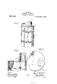
- Figure l is a perspective view of a powder can equipped with the closure constituting the best practical embodiment of my invention of which I am cognizant.
- Fig. 2 is an enlarged detail section, taken diametrically through the closure.
- Fig. 3 is a horizontal section taken in the plane indicated by the line 33 of Fig. 2, and showing the opening left in the head of the can when the original closure means thereof is removed.
- A is a powder can having in its head a an opening 6 of the conventional character or of any other kind consonant with the purpose of my invention.
- the wall of the opening 6 is shown in Fig. 8 as provided with equidistant, inwardly extending projections; the same being for the engagementof the original closure (not shown) of the can.
- Said projections have nothing whatever to do with my invention, and the opening 22 may, as before stated, be an opening such as shown or an opening of any other suitable character, without affecting my invention.
- B is the tubular body or major-portion of my novel closure.
- the said body is preferably of metal, is flanged at c to bear on and rest snug against the can head, and is provided with an upper reduced portion d and an exterior shoulder e at the lower end of said reduced portion.
- the closure comprises connectors C, and a removable cap D; the latter being of a size to snugly fit over and frictionally engage the upper reduced portion cl of the body so as not to be liable to accidental displacement.
- the connectors C are in the form of spring strips which are preferably arranged diametrically opposite each other and are connected at their upper ends to the body B, and provided at their lower ends with tapered heads f, the latter to pass through the opening Z) in the can head a and assume positions immediately below said head with a view of holding the flanged base of the body B tightly down on the head.
- the connectors are also provided at intermediate points of their length with finger-pieces E which extend radially outward through apertures g in body B and terminate in heads h.
- the connectors C tend to spring outwardly, and consequently serve to effect connection of the body B to the can head in such manner that there is no liability of the body being accidentally released during the use of the can. It will be noticed, however, thatwhen the user of the device by pressing inwardly on the finger-pieces E moves the connectors C inwardly sufiiciently far for the heads f of the latter to clear the wall of the opening I), the closure device as a whole may be removed from the can. Also when the connectors are pressed inwardly and moved downwardly through the opening Z) and then released, they will immediately reassume the positions shown in Fig. 2 and reelstablish the connection.
- my novel closure may be used on a number of cans in succession; also, that when the capD is removed powder may be poured through the tubular body B after the manner of a funnel. It will further be noted that a tight joint iseffected between the can head and the body B and a similar joint between the body B and the cap D, and consequently when the latter is in position on the body there is absolutely no liability of fire reaching the interior of the can through the closure. From this it follows that my improved closure is adapted to fully meet mining regulations concerning the care of powder no matter how strict the latter may be.
- the herein described closure for powder cans comprising a tubular body having an outwardly extending horizontal flange at its lower end, adapted to bear on the head of a can, around an opening in said head, a removable cap on the tubular body, resilient connectors fixedly connected at their upper ends to the inner side of the tubular body and extending through the lower end of the flan e b a s ace of a size to smwl receive the head of the can, and finger-pieces fixed to and extending outwardly from the connectors, at intermediate points in the length thereof, and also extending loosely through apertures in the wall of the tubular body.
Landscapes
- Engineering & Computer Science (AREA)
- Mechanical Engineering (AREA)
- Closures For Containers (AREA)
Description
G. W. GHILDS. CLOSURE FOR POWDER UANS.
APPLIGATION FILED 00114, 1908.
- Patented Nov. 16, 1909.
warm/m5 UNITED s ATEsIPAtrENT OFFICE.
GEORGE W. CI-IILDS, OF SEELEYVILLE, INDIANA.
CLOSURE FOR POWDER-CANS.
To all whom it may concern:
Be it known that I, GEORGE 'W. CHILDs, acitizen of the United States, residing at Seeleyville, in the county of Vigo and State of Indiana, have invented new and useful Improvements in Closures for Powder-Cans, of which the following is a specification.
My invention relates to closures for powder cans and analogous devices; and it has for its object to provide a simple, inexpensive and eflicient closure, susceptible of ready application to a can, and of use on a number of cans in succession, and one adapted to serve the additional function of a funnel and in that way facilitate the discharge of powder from the can.
\Vith the foregoing in view, the invention will be fully understood from the following description and claim when the same are read in connection with the drawings, accompanying and forming part of this specification, in which:
Figure l is a perspective view of a powder can equipped with the closure constituting the best practical embodiment of my invention of which I am cognizant. Fig. 2 is an enlarged detail section, taken diametrically through the closure. Fig. 3 is a horizontal section taken in the plane indicated by the line 33 of Fig. 2, and showing the opening left in the head of the can when the original closure means thereof is removed.
Similar letters designate corresponding parts in all of the views of the drawings, referring to which:
A is a powder can having in its head a an opening 6 of the conventional character or of any other kind consonant with the purpose of my invention. The wall of the opening 6 is shown in Fig. 8 as provided with equidistant, inwardly extending projections; the same being for the engagementof the original closure (not shown) of the can. Said projections, however, have nothing whatever to do with my invention, and the opening 22 may, as before stated, be an opening such as shown or an opening of any other suitable character, without affecting my invention.
B is the tubular body or major-portion of my novel closure. The said body is preferably of metal, is flanged at c to bear on and rest snug against the can head, and is provided with an upper reduced portion d and an exterior shoulder e at the lower end of said reduced portion.
Specification of Letters Patent.
Application filed. October 14, 1908.
Patented Nov. 16, 1909.
Serial No. 457,683.
In addition to the tubular body B, the closure comprises connectors C, and a removable cap D; the latter being of a size to snugly fit over and frictionally engage the upper reduced portion cl of the body so as not to be liable to accidental displacement.
As shown in Fig. 2 the connectors C are in the form of spring strips which are preferably arranged diametrically opposite each other and are connected at their upper ends to the body B, and provided at their lower ends with tapered heads f, the latter to pass through the opening Z) in the can head a and assume positions immediately below said head with a view of holding the flanged base of the body B tightly down on the head. The connectors are also provided at intermediate points of their length with finger-pieces E which extend radially outward through apertures g in body B and terminate in heads h.
As will be readily understood by reference to Fig. 2, the connectors C tend to spring outwardly, and consequently serve to effect connection of the body B to the can head in such manner that there is no liability of the body being accidentally released during the use of the can. It will be noticed, however, thatwhen the user of the device by pressing inwardly on the finger-pieces E moves the connectors C inwardly sufiiciently far for the heads f of the latter to clear the wall of the opening I), the closure device as a whole may be removed from the can. Also when the connectors are pressed inwardly and moved downwardly through the opening Z) and then released, they will immediately reassume the positions shown in Fig. 2 and reelstablish the connection.
It will be gathered from the foregoing that my novel closure may be used on a number of cans in succession; also, that when the capD is removed powder may be poured through the tubular body B after the manner of a funnel. It will further be noted that a tight joint iseffected between the can head and the body B and a similar joint between the body B and the cap D, and consequently when the latter is in position on the body there is absolutely no liability of fire reaching the interior of the can through the closure. From this it follows that my improved closure is adapted to fully meet mining regulations concerning the care of powder no matter how strict the latter may be.
As before stated the construction herein illustrated and described constitutes the best practical embodiment of my invention of which I am aware, but it is-obvious that in the future practice of the invention such changes or modifications may be made as fairly fall within the scope of my claimed invention. 7
Having described my invention, what I claim and desire to secure by Letters-Pat'- ent, is:
The herein described closure for powder cans, comprising a tubular body having an outwardly extending horizontal flange at its lower end, adapted to bear on the head of a can, around an opening in said head, a removable cap on the tubular body, resilient connectors fixedly connected at their upper ends to the inner side of the tubular body and extending through the lower end of the flan e b a s ace of a size to smwl receive the head of the can, and finger-pieces fixed to and extending outwardly from the connectors, at intermediate points in the length thereof, and also extending loosely through apertures in the wall of the tubular body.
In testimony whereof I have hereunto set my hand in presence of two subscribing witnesses.
GEORGE WV. CHILDS; Witnesses DONALD E. HINKLE, GEORGE BARKER.
Priority Applications (1)
| Application Number | Priority Date | Filing Date | Title |
|---|---|---|---|
| US45768308A US940128A (en) | 1908-10-14 | 1908-10-14 | Closure for powder-cans. |
Applications Claiming Priority (1)
| Application Number | Priority Date | Filing Date | Title |
|---|---|---|---|
| US45768308A US940128A (en) | 1908-10-14 | 1908-10-14 | Closure for powder-cans. |
Publications (1)
| Publication Number | Publication Date |
|---|---|
| US940128A true US940128A (en) | 1909-11-16 |
Family
ID=3008547
Family Applications (1)
| Application Number | Title | Priority Date | Filing Date |
|---|---|---|---|
| US45768308A Expired - Lifetime US940128A (en) | 1908-10-14 | 1908-10-14 | Closure for powder-cans. |
Country Status (1)
| Country | Link |
|---|---|
| US (1) | US940128A (en) |
Cited By (5)
| Publication number | Priority date | Publication date | Assignee | Title |
|---|---|---|---|---|
| US2560776A (en) * | 1947-10-14 | 1951-07-17 | Alfred W Peters | Pouring spout |
| US2643793A (en) * | 1952-04-15 | 1953-06-30 | Joe H Mcilroy | Can spout with punch and holddown latch |
| US2650739A (en) * | 1950-10-30 | 1953-09-01 | Ira S Boydstun | Volumetric measuring and dispensing device with container cutting and attaching means |
| US2867942A (en) * | 1953-04-15 | 1959-01-13 | Wintriss Inc | Whistle with integral attaching means |
| US3231156A (en) * | 1962-10-10 | 1966-01-25 | American Can Co | Container with snap-in plastic nozzle |
-
1908
- 1908-10-14 US US45768308A patent/US940128A/en not_active Expired - Lifetime
Cited By (5)
| Publication number | Priority date | Publication date | Assignee | Title |
|---|---|---|---|---|
| US2560776A (en) * | 1947-10-14 | 1951-07-17 | Alfred W Peters | Pouring spout |
| US2650739A (en) * | 1950-10-30 | 1953-09-01 | Ira S Boydstun | Volumetric measuring and dispensing device with container cutting and attaching means |
| US2643793A (en) * | 1952-04-15 | 1953-06-30 | Joe H Mcilroy | Can spout with punch and holddown latch |
| US2867942A (en) * | 1953-04-15 | 1959-01-13 | Wintriss Inc | Whistle with integral attaching means |
| US3231156A (en) * | 1962-10-10 | 1966-01-25 | American Can Co | Container with snap-in plastic nozzle |
Similar Documents
| Publication | Publication Date | Title |
|---|---|---|
| US3357605A (en) | Dispensing closure | |
| US933444A (en) | Paint-can. | |
| US3182694A (en) | Pill dispenser | |
| US2281642A (en) | Dispensing and bottle closure device | |
| US2190676A (en) | Sifter top container | |
| US1633420A (en) | Cap for containers | |
| US2448893A (en) | Cap for flasks or the like | |
| US5240154A (en) | Closure system for a container employing a bellows member | |
| US865406A (en) | Bottle-stopper. | |
| US1083552A (en) | Receptacle. | |
| US976887A (en) | Nipple-cover. | |
| US1165285A (en) | Pouring-lip for receptacles. | |
| US777609A (en) | Receptacle-cover. | |
| US1520006A (en) | Pouring spout and container | |
| US876504A (en) | Closure for oil-cans, jugs, &c. | |
| US1085335A (en) | Powder-can spout. | |
| US2642204A (en) | Permanently attached closure device for containers | |
| US2360543A (en) | Dispensing container | |
| US424115A (en) | Guipowdee can | |
| US794292A (en) | Baking-pan. | |
| US979592A (en) | Dispensing-receptacle. | |
| US1521496A (en) | Powder duster | |
| JPH0138050Y2 (en) | ||
| US892092A (en) | Can-spout. | |
| US676774A (en) | Jar-closure. |