US9400323B2 - Passive radar device - Google Patents
Passive radar device Download PDFInfo
- Publication number
- US9400323B2 US9400323B2 US13/984,936 US201113984936A US9400323B2 US 9400323 B2 US9400323 B2 US 9400323B2 US 201113984936 A US201113984936 A US 201113984936A US 9400323 B2 US9400323 B2 US 9400323B2
- Authority
- US
- United States
- Prior art keywords
- block
- doppler
- pulse
- bandwidth
- frequency spectrum
- Prior art date
- Legal status (The legal status is an assumption and is not a legal conclusion. Google has not performed a legal analysis and makes no representation as to the accuracy of the status listed.)
- Expired - Fee Related, expires
Links
Images
Classifications
-
- G—PHYSICS
- G01—MEASURING; TESTING
- G01S—RADIO DIRECTION-FINDING; RADIO NAVIGATION; DETERMINING DISTANCE OR VELOCITY BY USE OF RADIO WAVES; LOCATING OR PRESENCE-DETECTING BY USE OF THE REFLECTION OR RERADIATION OF RADIO WAVES; ANALOGOUS ARRANGEMENTS USING OTHER WAVES
- G01S7/00—Details of systems according to groups G01S13/00, G01S15/00, G01S17/00
- G01S7/02—Details of systems according to groups G01S13/00, G01S15/00, G01S17/00 of systems according to group G01S13/00
- G01S7/28—Details of pulse systems
- G01S7/285—Receivers
-
- G—PHYSICS
- G01—MEASURING; TESTING
- G01S—RADIO DIRECTION-FINDING; RADIO NAVIGATION; DETERMINING DISTANCE OR VELOCITY BY USE OF RADIO WAVES; LOCATING OR PRESENCE-DETECTING BY USE OF THE REFLECTION OR RERADIATION OF RADIO WAVES; ANALOGOUS ARRANGEMENTS USING OTHER WAVES
- G01S13/00—Systems using the reflection or reradiation of radio waves, e.g. radar systems; Analogous systems using reflection or reradiation of waves whose nature or wavelength is irrelevant or unspecified
- G01S13/02—Systems using reflection of radio waves, e.g. primary radar systems; Analogous systems
- G01S13/06—Systems determining position data of a target
- G01S13/46—Indirect determination of position data
-
- G—PHYSICS
- G01—MEASURING; TESTING
- G01S—RADIO DIRECTION-FINDING; RADIO NAVIGATION; DETERMINING DISTANCE OR VELOCITY BY USE OF RADIO WAVES; LOCATING OR PRESENCE-DETECTING BY USE OF THE REFLECTION OR RERADIATION OF RADIO WAVES; ANALOGOUS ARRANGEMENTS USING OTHER WAVES
- G01S13/00—Systems using the reflection or reradiation of radio waves, e.g. radar systems; Analogous systems using reflection or reradiation of waves whose nature or wavelength is irrelevant or unspecified
- G01S13/02—Systems using reflection of radio waves, e.g. primary radar systems; Analogous systems
- G01S13/50—Systems of measurement based on relative movement of target
- G01S13/52—Discriminating between fixed and moving objects or between objects moving at different speeds
- G01S13/522—Discriminating between fixed and moving objects or between objects moving at different speeds using transmissions of interrupted pulse modulated waves
- G01S13/524—Discriminating between fixed and moving objects or between objects moving at different speeds using transmissions of interrupted pulse modulated waves based upon the phase or frequency shift resulting from movement of objects, with reference to the transmitted signals, e.g. coherent MTi
- G01S13/5244—Adaptive clutter cancellation
-
- G—PHYSICS
- G01—MEASURING; TESTING
- G01S—RADIO DIRECTION-FINDING; RADIO NAVIGATION; DETERMINING DISTANCE OR VELOCITY BY USE OF RADIO WAVES; LOCATING OR PRESENCE-DETECTING BY USE OF THE REFLECTION OR RERADIATION OF RADIO WAVES; ANALOGOUS ARRANGEMENTS USING OTHER WAVES
- G01S13/00—Systems using the reflection or reradiation of radio waves, e.g. radar systems; Analogous systems using reflection or reradiation of waves whose nature or wavelength is irrelevant or unspecified
- G01S13/02—Systems using reflection of radio waves, e.g. primary radar systems; Analogous systems
- G01S13/50—Systems of measurement based on relative movement of target
- G01S13/52—Discriminating between fixed and moving objects or between objects moving at different speeds
- G01S13/522—Discriminating between fixed and moving objects or between objects moving at different speeds using transmissions of interrupted pulse modulated waves
- G01S13/524—Discriminating between fixed and moving objects or between objects moving at different speeds using transmissions of interrupted pulse modulated waves based upon the phase or frequency shift resulting from movement of objects, with reference to the transmitted signals, e.g. coherent MTi
- G01S13/5246—Discriminating between fixed and moving objects or between objects moving at different speeds using transmissions of interrupted pulse modulated waves based upon the phase or frequency shift resulting from movement of objects, with reference to the transmitted signals, e.g. coherent MTi post processors for coherent MTI discriminators, e.g. residue cancellers, CFAR after Doppler filters
-
- G—PHYSICS
- G01—MEASURING; TESTING
- G01S—RADIO DIRECTION-FINDING; RADIO NAVIGATION; DETERMINING DISTANCE OR VELOCITY BY USE OF RADIO WAVES; LOCATING OR PRESENCE-DETECTING BY USE OF THE REFLECTION OR RERADIATION OF RADIO WAVES; ANALOGOUS ARRANGEMENTS USING OTHER WAVES
- G01S13/00—Systems using the reflection or reradiation of radio waves, e.g. radar systems; Analogous systems using reflection or reradiation of waves whose nature or wavelength is irrelevant or unspecified
- G01S13/87—Combinations of radar systems, e.g. primary radar and secondary radar
- G01S13/878—Combination of several spaced transmitters or receivers of known location for determining the position of a transponder or a reflector
Definitions
- the present invention relates to a passive radar device that uses a radio wave transmitted from an existing radio source to detect an azimuth of a target, a distance therefrom, and the like based on a signal that directly arrives from the radio source and a signal scattered by the target.
- a passive radar device is a device that uses a radio wave transmitted from an existing radio source such as a broadcasting station to detect an azimuth of a target, a distance therefrom, and the like by measuring a path length difference between a signal (direct wave) that directly arrives from the radio source and a signal (scattered wave) scattered by the target and a Doppler frequency shift of a scattered-wave signal.
- examples considered as the radio source include a global navigation satellite system (GNSS) in addition to a television or radio broadcasting station.
- GNSS global navigation satellite system
- a passive radar is attracting attention as a system useful for power saving and radio wave resource saving because of not emitting a radio wave itself (see, for example, Non Patent Literature 1).
- a passive radar system has the most significant object of stretching a detection range.
- the reason that it is particularly difficult to stretch the detection range with the passive radar system is because power of the radio wave transmitted from the radio source is feeble compared to a detection radar such as a conventional active system, which extremely lowers a signal to noise ratio (SNR).
- SNR signal to noise ratio
- Patent Literatures 1 to 3 propose a method of observing a target for as long a period as possible and extending an integration time of a signal, to thereby increase a Doppler frequency resolution and improve the SNR.
- Patent Literatures 1 to 3 propose a countermeasure against this problem.
- a target candidate is first detected by using a result of performing Doppler processing for a relatively short integration time, and then a target signal is corrected by using a Doppler frequency of a detected signal.
- a target needs to be detected once to some extent within the relatively short integration time. This raises a problem in that an SNR cannot be improved sufficiently.
- Non Patent Literatures 2 and 3 have a problem in that an increase in calculation amount causes processing load on the device to become heavier.
- the present invention has been made in order to solve the problems as described above, and an object thereof is to obtain a passive radar device capable of extending an observing time for a target and an integration time of a signal with a small calculation amount, sufficiently improving an SNR, and stretching a detection range.
- a passive radar device including: an antenna for direct-wave reception for receiving a direct wave that directly arrives after being transmitted from a radio source; an antenna for scattered-wave reception for receiving a scattered wave transmitted from the radio source and scattered by a target; a direct-wave reception unit for dividing a received signal of the direct wave into pulses; a scattered-wave reception unit for dividing a received signal of the scattered wave into pulses; a pulse-by-pulse range compression unit for executing cross-correlation processing between the received signal of the direct wave and the received signal of the scattered wave on each of the divided pulses and calculating a pulse-by-pulse range profile; a block-by-block Doppler processing unit for calculating a first Doppler frequency spectrum by executing pulse-direction Fourier transform in units of blocks each of which groups a plurality of pulses; a Doppler frequency cell-associated range migration compensation unit for compensating a range-direction movement amount with respect to the first Doppler frequency spectrum on
- the passive radar device includes: the pulse-by-pulse range compression unit for executing the cross-correlation processing between the received signal of the direct wave and the received signal of the scattered wave on each of the pulses divided by the direct-wave reception unit and the scattered-wave reception unit and calculating the pulse-by-pulse range profile; the block-by-block Doppler processing unit for calculating the first Doppler frequency spectrum by executing the pulse-direction Fourier transform in units of blocks each of which groups the plurality of pulses; the Doppler frequency cell-associated range migration compensation unit for compensating the range-direction movement amount with respect to the first Doppler frequency spectrum on a Doppler-frequency-cell-by-Doppler-frequency-cell basis and on a block-by-block basis; and the block-direction Doppler processing unit for calculating the second Doppler frequency spectrum by executing the block-direction Fourier transform on the output from the Doppler frequency cell-associated range migration compensation unit.
- the problem is simplified so as to limit a movement of the target signal to a linear movement in a range direction. Further, by dividing data that has been observed for a long period into short pulses, long-period correlation processing between a direct wave and a scattered wave is formed by FFT, and processing in units of blocks each of which groups a plurality of pulses is introduced, to thereby speed up handling of range migration during the observing time.
- the passive radar device capable of extending the observing time for the target and the integration time of the signal with a small calculation amount, sufficiently improving the SNR, and stretching the detection range.
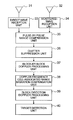
- FIG. 1 is an explanatory diagram illustrating a concept of a passive radar along with a geometry of observation.
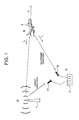
- FIG. 2 is a block diagram illustrating a passive radar device according to a first embodiment of the present invention.
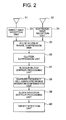
- FIG. 3 is an explanatory diagram illustrating handling of a received signal in processing performed by the passive radar device according to the first embodiment of the present invention.
- FIG. 4 is a block diagram illustrating a pulse-by-pulse range compression unit of the passive radar device according to the first embodiment of the present invention.
- FIGS. 5A and 5B are explanatory diagrams illustrating processing performed by a Doppler frequency cell-associated range migration compensation unit of the passive radar device according to the first embodiment of the present invention.
- FIG. 6 is a block diagram illustrating the Doppler frequency cell-associated range migration compensation unit of the passive radar device according to the first embodiment of the present invention.
- FIG. 7 is a block diagram illustrating a passive radar device according to a second embodiment of the present invention.
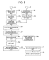
- FIG. 8 is a block diagram illustrating a passive radar device according to a third embodiment of the present invention.
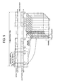
- FIG. 9 is an explanatory diagram illustrating handling of a received signal in processing performed by the passive radar device according to the third embodiment of the present invention.
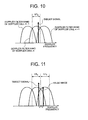
- FIG. 10 is an explanatory diagram illustrating properties of a signal handled in the processing performed by the passive radar device according to the third embodiment of the present invention.
- FIG. 11 is an explanatory diagram illustrating properties of the signal handled in the processing performed by the passive radar device according to the third embodiment of the present invention.
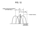
- FIG. 12 is an explanatory diagram illustrating properties of the signal handled in the processing performed by the passive radar device according to the third embodiment of the present invention.
- FIG. 13 is another block diagram illustrating the passive radar device according to the third embodiment of the present invention.
- a variable “a” above which “ ” is added represents a vector, and is described as “a (bar)” in the Description.
- the variable “a” above which “ ⁇ ” is added represents a unit vector, and is described as “a (hat)” in the Description.
- the variable “a” above which “ ⁇ tilde over ( ) ⁇ ” is added represents an estimated value, and is described as “a (tilde)” in the Description.
- the variable “a” above which “ ⁇ dot over ( ) ⁇ ” is added represents a rate of temporal change, and is described as “a (dot)” in the Description.
- the variable “a” above which inverted “ ⁇ ” is added represents a compensated value, and is described as “a (breve)” in the Description.
- FIG. 1 is an explanatory diagram illustrating a concept of a passive radar along with a geometry of observation.
- a radio wave transmitted from a broadcasting station 1 being a radio source is received by an antenna 31 for direct-wave reception and an antenna 32 for scattered-wave reception that are provided to a receiving station 3 .
- the antenna 31 for direct-wave reception is disposed so as to be directed toward the broadcasting station 1 , and receives a radio wave (direct wave) that directly arrives after being transmitted from the broadcasting station 1 .
- the antenna 32 for scattered-wave reception is disposed so as to be directed toward an observed area in which a target 2 exists, and receives a radio wave (scattered wave) that has been transmitted from the broadcasting station 1 and scattered by the target 2 .
- the broadcasting station 1 is continuously transmitting (broadcasting) a signal having a carrier frequency f c and a signal band B.
- the receiving station 3 amplifies each of signals received through the antenna 31 for direct-wave reception and the antenna 32 for scattered-wave reception, extracts signals having a desired band through a band filter, and then samples the downconverted signals.
- the respective embodiments of the present invention are described on the assumption that the antenna 31 for direct-wave reception and the antenna 32 for scattered-wave reception are antennas different from each other, but the present invention is not limited thereto, and two or more antennas may be used to receive the radio wave transmitted from the broadcasting station 1 and split the radio wave into the direct wave and the scattered wave by digital beam forming.
- two antennas for scattered-wave reception having polarization characteristics orthogonal to each other can be used to measure polarization characteristics of scattering caused by a target as well.
- each processing described below to signals obtained through the two antennas for scattered-wave reception, it is possible to generate two radar images having polarization characteristics different from each other.
- p s (bar) and p r (bar) are position vectors indicating fixed positions of the broadcasting station 1 and the receiving station 3 , respectively.
- p t (bar) and v(bar) are vectors indicating a center of gravity and a speed of the target 2 , respectively.
- i s (hat) and i r (hat) are unit vectors indicating directions from the target 2 toward the broadcasting station 1 and the receiving station 3 , respectively, and are expressed as the following Expression (1).
- distances r s and r r between the target 2 and the broadcasting station 1 and the receiving station 3 , respectively, and a distance r d between the broadcasting station 1 and the receiving station 3 are defined by the following Expression (2).
- p t (bar), v(bar), i s (hat), i r (hat), r s , and r r are functions of a time instant t, and are explicitly described below as p t (t) (bar) or the like as necessary.
- FIG. 2 is a block diagram illustrating a passive radar device according to the first embodiment of the present invention.
- the passive radar device includes the antenna 31 for direct-wave reception, the antenna 32 for scattered-wave reception, a direct-wave reception unit 33 , a scattered-wave reception unit 34 , a pulse-by-pulse range compression unit 35 , a clutter suppression unit 36 , a block-by-block Doppler processing unit 37 , a Doppler frequency cell-associated range migration compensation unit 38 , a block-direction Doppler processing unit 39 , and a target detection unit 40 .
- the direct-wave reception unit 33 and the scattered-wave reception unit 34 are provided to the receiving station 3 .
- FIG. 3 is an explanatory diagram illustrating handling of a received signal in processing performed by the passive radar device according to the first embodiment of the present invention.
- a horizontal axis thereof represents a time instant.
- the direct-wave reception unit 33 and the scattered-wave reception unit 34 each receive a signal during an observing time T [sec] illustrated in FIG. 3 . Further, the direct-wave reception unit 33 and the scattered-wave reception unit 34 each divide the received signal into H blocks of T b [sec], and divide each of the blocks into N pulses of T 0 [sec].
- the received signal is divided into pulses, which are grouped into blocks, in order to realize the speeding up of the processing.
- long-period correlation processing between the direct wave and the scattered wave can be all formed by the fast Fourier transform (FFT). Further, by performing the processing in units of blocks each of which groups several pulses, it is possible to speed up handling of range migration during the observing time.
- FFT fast Fourier transform
- a wave transmitted from the broadcasting station 1 is a narrow-band signal having a center frequency of f c , and hence a received signal s d (t) (tilde) of the direct wave received from the broadcasting station 1 in the position of the receiving station 3 is expressed by the following Expression (4).
- ⁇ tilde over (s) ⁇ d ( t ) a ( t ⁇ d )exp ⁇ j 2 ⁇ f c ( t ⁇ d ) ⁇ (4)
- a(t) represents a complex amplitude of a transmitted signal
- ⁇ d represents a propagation delay time of the direct wave.
- the transmitted signal is unknown, and it is appropriate to handle a complex amplitude a(t) as a random process. Further, in the following description, it is assumed that wide-sense stationary (WSS) is established.
- WSS wide-sense stationary
- ⁇ d is a constant.
- ⁇ represents an amplitude ratio due to a difference in attenuation ascribable to a difference in propagation length
- the rate of change ⁇ sn (dot) in the propagation delay time is sufficiently small, and hence, with regard to the term of the complex amplitude a(t), it is assumed that the propagation delay time is ⁇ sn0 and constant during the pulse width T 0 .
- time delays ⁇ d and ⁇ sn0 of the direct wave and the scattered wave, respectively, and a Doppler frequency f dn of the scattered wave are each obtained as the following Expressions (8) to (10).
- c represents a light velocity.
- k s (t) (bar) and k r (t) (bar) represent wave number vectors at the time instant t, and are defined by the following Expression (11).
- Expression (10) is derived by using a relationship of temporal differentiation of a distance r s (t) expressed by the following Expression (12). Note that, the same applies to the distance r s (t).
- ⁇ represents an initial phase of a local oscillator. Note that, the last equation of Expression (14) expresses the received signal s sn (t) of the scattered wave by using the received signal s dn (t) of the direct wave.
- the pulse-by-pulse range compression unit 35 executes range compression by cross-correlation processing described below on a pulse-by-pulse basis.
- a cross-correlation function x n ( ⁇ ) of the following Expression (15) obtained by the cross-correlation processing is referred to as “range profile” in the respective embodiments of the present invention.
- a ⁇ ( ⁇ ) ⁇ ⁇ ⁇ ( T 0 - ⁇ ) ⁇ exp ⁇ ( j ⁇ ⁇ ⁇ f dn ⁇ ⁇ ) ⁇ sin ⁇ ⁇ ⁇ ⁇ ⁇ f dn ⁇ ( T 0 - ⁇ ) ⁇ ⁇ ⁇ ⁇ f dn ⁇ ( T 0 - ⁇ ) ⁇ ⁇ ⁇ ⁇ ( T 0 - ⁇ ) ⁇ ⁇ ( f dn ⁇ ⁇ ⁇ f dn ⁇ T 0 ⁇ ⁇ 1 ) ( 19 )
- the term of a sinc function is a term indicating a loss of a correlation between the scattered wave and the direct wave which occurs due to the fact that the scattered wave is subjected to a Doppler shift caused by a movement of the target 2 , but if the pulse width T 0 is short, this loss can be ignored, and an approximation of Expression (19) is established. Further, in Expression (19), from the term of (T 0 ⁇ ), it is understood that the pulse width T 0 needs to be sufficiently longer than a conceivable time delay difference.
- the received signal s dn (t) of the direct wave the received signal s sn (t) of the scattered wave, the range profile x n ( ⁇ ), and the like have been so far formulated as continuous analog signals, but in terms of implementation, become digital signals discretized by sampling.
- the pulse-by-pulse range compression unit 35 uses the cross-correlation processing expressed by the above-mentioned Expression (15) to calculate and output the range profile.
- a cross-correlation function calculated by the above-mentioned Expression (15) may be substituted by a circular cross-correlation function obtained by high-speed calculation using the FFT, to thereby speed up the processing.
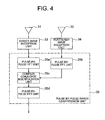
- FIG. 4 is a block diagram illustrating a case where the pulse-by-pulse range compression unit 35 is formed of high-speed calculation blocks using the FFT in the passive radar device according to the first embodiment of the present invention.
- the pulse-by-pulse range compression unit 35 includes pulse-by-pulse FFT units 35 a and 35 b , a complex conjugate multiplication unit 35 c , and a pulse-by-pulse IFFT unit 35 d.
- the pulse-by-pulse FFT unit 35 a and the pulse-by-pulse FFT unit 35 b divide a direct-wave signal and a scattered-wave signal, which are received by the direct-wave reception unit 33 and the scattered-wave reception unit 34 , respectively, into pulses having the pulse width T 0 , and then apply the FFT to each of the pulses.
- the complex conjugate multiplication unit 35 c executes complex conjugate multiplication processing between corresponding pulses in signals after the FFT of the direct-wave signal and the scattered-wave signal, which are obtained by the pulse-by-pulse FFT units 35 a and 35 b , respectively. Specifically, the complex conjugate multiplication unit 35 c executes processing for multiplying, for each element, a complex conjugate signal of the signal after the FFT of the direct-wave signal by the signal after the FFT of the scattered-wave signal. An output signal from the complex conjugate multiplication unit 35 c is output to the pulse-by-pulse IFFT unit 35 d.
- the pulse-by-pulse IFFT unit 35 d applies inverse fast Fourier transform (IFFT) processing to the signal output from the complex conjugate multiplication unit 35 c , to thereby calculate and output the circular cross-correlation function.
- IFFT inverse fast Fourier transform
- the circular cross-correlation function can sufficiently approximate the range profile obtained by the cross-correlation processing of the above-mentioned Expression (15). Accordingly, in the following description, the circular cross-correlation function obtained by the pulse-by-pulse range compression unit 35 illustrated in FIG. 4 is also referred to as “range profile”.
- the processing of the clutter suppression unit 36 is formulated as the following Expression (21).
- the clutter suppression unit 36 outputs a signal x n ( ⁇ ) (breve) calculated by Expression (21).
- the time delay difference does not change on a pulse-by-pulse basis.
- the signal of the reflected wave from the stationary object is not subject to the Doppler frequency shift.
- the clutter suppression unit 36 averages the range profiles of N pulses to extract a signal having a Doppler frequency of zero, and subtracts this signal from each of the range profiles, to thereby suppress the signal having the Doppler frequency of zero. This can suppress the reflected signal from the stationary object in the background.
- the clutter suppression unit 36 is not an essential component to the first embodiment of the present invention. Even if the processing of the clutter suppression unit 36 is omitted, the other components can execute the same processing.
- the block-by-block Doppler processing unit 37 calculates a Doppler frequency spectrum (first Doppler frequency spectrum) by executing pulse-direction discrete Fourier transform in units of blocks.
- the range profiles of all the pulses and all the blocks that are obtained as a result of range compression processing performed by the pulse-by-pulse range compression unit 35 are expressed as the following Expression (22).
- the pulse number has been so far designated by numbers consecutive across all the blocks, but is now initialized for each of the blocks. This is merely for convenience of description, and a substance of the signal is the same.
- the block-by-block Doppler processing unit 37 calculates the Doppler frequency spectrum by executing the pulse-direction discrete Fourier transform on a range-by-range basis as expressed by the following Expression (23) in each block.
- the block-by-block Doppler processing unit 37 outputs a signal y h ( ⁇ , f dm ).
- the Doppler frequency spectrum of the target 2 can be calculated by executing the pulse-direction discrete Fourier transform on a range-by-range basis as expressed in the above-mentioned Expression (23).
- C h represents the complex amplitude at the peak observed in the h-th block, and is expressed by the following Expression (30).
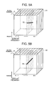
- FIGS. 5A and 5B are explanatory diagrams illustrating the processing performed by the Doppler frequency cell-associated range migration compensation unit 38 of the passive radar device according to the first embodiment of the present invention.
- FIG. 5A illustrates an output signal 51 from the block-by-block Doppler processing unit 37 , indicating a signal after pulse-by-pulse range compression processing and block-by-block Doppler processing and before Doppler frequency cell-associated range migration compensation processing.
- FIG. 5B illustrates an output signal 53 from the Doppler frequency cell-associated range migration compensation unit 38 , indicating a signal after the pulse-by-pulse range compression processing, the block-by-block Doppler processing, and the Doppler frequency cell-associated range migration compensation processing.
- FIGS. 5A and 5B illustrate a case of receiving the scattered-wave signal from a moving point target as an example, and point target signals 52 and 54 each express the scattered-wave signal received from the moving point target.
- the point target signal 52 is compressed in a range (corresponding to propagation delay distance difference) direction and a Doppler frequency direction in each block, and is observed as a point image on a range-Doppler map defined on a block-by-block basis.
- a two-dimensional data array extending in the range direction and the Doppler frequency direction corresponding to a given block number is defined as the range-Doppler map.
- a peak position of the point image is ⁇ hN in the range direction and f d ⁇ (f c ⁇ f c )/f c in the Doppler frequency direction.
- the peak position of the point image is indicated by the bold line of the point target signal 52 .
- the point target signal 52 indicates that the position in the Doppler frequency direction of the point image does not change on a block-by-block basis, while the position in the range direction changes on a block-by-block basis.
- the Doppler frequency cell-associated range migration compensation unit 38 first compensates the movement (migration) of the point image in the range direction. At this time, the Doppler frequency of the signal included in the m-th Doppler frequency cell is f dm , and hence a time delay ⁇ m,h in the h-th block makes a linear temporal change so as to correspond to the Doppler frequency, and is expressed by the following Expression (31).
- the ranges of the signal can be made to coincide with one another.
- the signal obtained by thus compensating the range-direction movement amount is referred to as “y h ( ⁇ , f dm ) (breve)” below.
- the Doppler frequency cell-associated range migration compensation unit 38 outputs the signal y h ( ⁇ , f dm ) (breve) obtained by compensating the range-direction movement amount.
- the output signal 53 of FIG. 5B indicates a concept diagram of the signal y h ( ⁇ , f dm ) (breve).
- the Doppler frequency cell-associated range migration compensation unit 38 executes processing for moving the signal y h ( ⁇ , f dm ) output by the block-by-block Doppler processing unit 37 by the range-direction movement amount expressed by the above-mentioned Expression (31), to thereby align the ranges of the signal received from a moving target across the blocks as in the output signal 53 of FIG. 5B .
- the Doppler frequency cell-associated range migration compensation unit 38 can perform the processing by a method of shifting the signal y h ( ⁇ , f dm ) itself, which is output by the block-by-block Doppler processing unit 37 , in the range direction by the range-direction movement amount expressed by the above-mentioned Expression (31), but can realize higher-speed processing by processing based on a shift rule of Fourier transform described below.
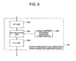
- FIG. 6 is a block diagram illustrating the Doppler frequency cell-associated range migration compensation unit 38 in a case where range migration compensation processing based on the shift rule of the Fourier transform is executed in the passive radar device according to the first embodiment of the present invention.
- the Doppler frequency cell-associated range migration compensation unit 38 includes an FFT unit 38 a , a phase function 38 b for range migration compensation, a multiplication unit 38 c , and an IFFT unit 38 d.
- the FFT unit 38 a executes Fourier transform processing expressed by the following Expression (32) by the FFT to perform Fourier-transform in the range direction.
- F ⁇ g ⁇ represents the Fourier transform of a function g.
- the phase function 38 b for range migration compensation is a phase function for compensating a phase change corresponding to a block-direction range migration amount corresponding to each of the Doppler frequency cells in the signal y h ( ⁇ , f dm ) output by the block-by-block Doppler processing unit 37 , and is expressed by the following Expression.
- the multiplication unit 38 c uses the calculation expressed by the following Expression (33) to multiply an output Y h (f, f dm ) of the Fourier transform of the above-mentioned Expression (32) by the phase function corresponding to the range-direction movement amount.
- the IFFT unit 38 d executes inverse Fourier transform processing by the IFFT on a signal Y h (f, f dm ) (breve) obtained as a result of Expression (33) as expressed by the following Expression (34), to thereby obtain the signal y h ( ⁇ , f dm ) (breve) in which the range-direction movement amount expressed by the above-mentioned Expression (31) is compensated.
- the block-direction Doppler processing unit 39 calculates a Doppler frequency spectrum (second Doppler frequency spectrum) by executing block-direction discrete Fourier transform on the signal y h ( ⁇ , f dm ) (breve) for each range-Doppler cell as expressed by the following Expression (35).
- the block-direction Doppler processing unit 39 outputs a signal z( ⁇ , f dm , f dl ) calculated by Expression (35).
- an expected value being a result of the block-direction discrete Fourier transform in the range-Doppler cell in which the target signal exists is expressed by the following Expression (36).
- Expression (36) by assuming that the target amplitude does not change during the observing time T, an approximation is established as ⁇ (T 0 ⁇ hN ) ⁇ (T 0 ⁇ 0 ). Further, from Expression (36), it is understood as a result of block-direction Fourier transform that a peak occurs in the Doppler frequency cell satisfying the following Expression (37).
- D represents the complex amplitude at the peak, and is expressed by the following Expression (38).
- both the pulse direction and the block direction are converted into dimensions of the Doppler frequency. Accordingly, the signal z( ⁇ , f dm , f dl ) can be easily converted into one range-Doppler map by being appropriately rearranged.
- the pulse width T 0 and the block width T b are determined by the following procedure. It should be noted that the observing time T is given as a result of feasibility study and is not a parameter that accompanies a system according to the first embodiment of the present invention.
- an upper limit of an absolute value of the Doppler frequency that can be observed is set to f dmax .
- the pulse width T 0 can be determined based on the following Expression (39).
- an upper limit of the number N of pulses within the block is given by the above-mentioned Expression (25). Accordingly, after the pulse width T 0 is determined so as to satisfy the condition expressed by Expression (39), the block width T b may be determined so as to satisfy a relationship expressed by the following Expression (40).
- the target detection unit 40 calculates an intensity P ( ⁇ , f dm , f dl ) thereof by the following Expression (41).
- P ( ⁇ , f dm ,f dl )
- the target detection unit 40 detects the target signal by applying detection processing such as a constant false alarm rate (CFAR) processing to an intensity signal P ( ⁇ , f dm , f dl ).
- detection processing such as a constant false alarm rate (CFAR) processing
- CFAR constant false alarm rate
- P intensity signal
- the intensity signal P ( ⁇ , f dm , f dl ) may be incoherently integrated across a plurality of cells adjacent to each other in terms of the range direction, the Doppler frequency direction, or both thereof.
- a standard deviation of noise components can be reduced, and signal components can be incoherently integrated in a case where the target signal extends toward the range direction, the Doppler frequency direction, or both thereof, which can improve the SNR.
- the passive radar device includes: the pulse-by-pulse range compression unit for executing the cross-correlation processing between the received signal of the direct wave and the received signal of the scattered wave on each of the pulses divided by the direct-wave reception unit and the scattered-wave reception unit and calculating a pulse-by-pulse range profile; the block-by-block Doppler processing unit for calculating the first Doppler frequency spectrum by executing pulse-direction Fourier transform in units of blocks each of which groups a plurality of pulses; the Doppler frequency cell-associated range migration compensation unit for compensating a range-direction movement amount with respect to the first Doppler frequency spectrum on a Doppler-frequency-cell-by-Doppler-frequency-cell basis and on a block-by-block basis; and the block-direction Doppler processing unit for calculating the second Doppler frequency spectrum by executing the block-direction Fourier transform on the output from the Doppler frequency cell-associated range migration compensation unit.
- the processing is executed by dividing the received signal in units of pulses and blocks, and the range migration compensation processing is executed on a Doppler-frequency-cell-by-Doppler-frequency-cell basis before the block-direction processing is executed, which allows integration over a long period to be performed on the signal received from the moving target. Further, each processing is executed only by multiplication between the FFT and a complex number, which can greatly reduce a calculation amount.
- the passive radar device capable of extending the observing time for the target and an integration time of a signal with a small calculation amount, sufficiently improving the SNR, and stretching a detection range.
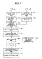
- FIG. 7 is a block diagram illustrating a passive radar device according to a second embodiment of the present invention.
- the passive radar device includes the antenna 31 for direct-wave reception, the antenna 32 for scattered-wave reception, the direct-wave reception unit 33 , the scattered-wave reception unit 34 , the pulse-by-pulse FFT unit 35 a , the pulse-by-pulse FFT unit 35 b , the complex conjugate multiplication unit 35 c , the clutter suppression unit 36 , the block-by-block Doppler processing unit 37 , the phase function 38 b for range migration compensation, the multiplication unit 38 c , the IFFT unit 38 d , the block-direction Doppler processing unit 39 , and the target detection unit 40 .
- the pulse-by-pulse FFT unit 35 a the pulse-by-pulse FFT unit 35 b , and the complex conjugate multiplication unit 35 c , and the phase function 38 b for range migration compensation, the multiplication unit 38 c , and the IFFT unit 38 d are the same as those illustrated in FIGS. 4 and 6 , respectively.
- the clutter suppression unit 36 and the block-by-block Doppler processing unit 37 are sandwiched by the pulse-by-pulse IFFT unit 35 d and the FFT unit 38 a.
- the clutter suppression unit 36 and the block-by-block Doppler processing unit 37 are both processing that is constant in the range direction, and hence, when the components illustrated in FIGS. 4 and 6 are inserted into the components illustrated in FIG. 2 , respectively, there occurs processing for again performing Fourier-transform on what is temporarily inverse-Fourier-transformed in the range direction without adding any range-direction processing, which causes the calculation amount to increase.
- the pulse-by-pulse IFFT unit 35 d and the FFT unit 38 a are omitted. With such a configuration, it is possible to prevent the calculation amount from increasing and to speed up the processing.
- the pulse-by-pulse range compression unit includes: the pulse-by-pulse FFT unit for dividing the received signal of the direct wave and the received signal of the scattered wave into pulses, and Fourier-transforming each thereof; and the complex conjugate multiplication unit for multiplying the complex conjugate signal of the received signal of the direct wave which is Fourier-transformed by the pulse-by-pulse FFT unit by the received signal of the scattered wave which is Fourier-transformed by the pulse-by-pulse FFT unit; and the Doppler frequency cell-associated range migration compensation unit includes: the multiplication unit for multiplying the first Doppler frequency spectrum by a phase function for range migration compensation for compensating a phase change corresponding to the block-direction range migration amount corresponding to each of the Doppler frequency cells in the first Doppler frequency spectrum; and the IFFT unit for executing the inverse Fourier transform on the output from the multiplication unit.
- FIG. 8 is a block diagram illustrating a passive radar device according to a third embodiment of the present invention.
- the passive radar device further includes a block signal addition unit 41 in addition to the components of the passive radar device illustrated in FIG. 7 .
- the other components are the same as those of the second embodiment described above, and hence descriptions thereof are omitted.
- FIG. 9 is an explanatory diagram illustrating handling of a received signal in processing performed by the passive radar device according to the third embodiment of the present invention.
- FIG. 9 is substantially the same as FIG. 3 , and hence a description is made of only different points from FIG. 3 .
- the blocks are set so that the adjacent blocks do not overlap each other, while in FIG. 9 , the adjacent blocks overlap each other.
- the pulses forming the second block have the pulse numbers of N to 2N ⁇ 1, while in FIG. 9 , the pulses forming the second block have the pulse numbers of 1 to N.
- the number of blocks is H in the case where the blocks are set so as not to overlap each other as in FIG. 3 , while in the case where the blocks are set as in FIG. 9 , the number of set blocks is (H ⁇ 1)N.
- the adjacent blocks are set so as to be shifted by one pulse, but the present invention is not limited thereto, and more generally, the adjacent blocks may be set so as to be shifted by a plurality of pulses.
- FIGS. 10 to 12 are explanatory diagrams illustrating properties of a signal handled in the processing performed by the passive radar device according to the third embodiment of the present invention.
- FIG. 10 is a schematic diagram illustrating Doppler filter bands obtained as a result of the Doppler processing performed by the block-by-block Doppler processing unit 37 .
- the target signal is included in the Doppler filter band of a Doppler cell m.
- FIG. 10 also illustrates the Doppler filter bands of adjacent Doppler cells.
- a bandwidth 1/T b of the Doppler frequency spectrum in block-direction Doppler processing performed by the block-direction Doppler processing unit 39 according to the first and second embodiments is indicated by being surrounded by the broken lines.
- the blocks are set so that the adjacent blocks do not overlap each other, and hence the repetition interval between the blocks coincides with the block width T b . Therefore, the bandwidth of the Doppler frequency spectrum in the block-direction Doppler processing performed by the block-direction Doppler processing unit 39 is 1/T b .
- FIG. 11 is a schematic diagram illustrating that a false image may occur as a result of the block-direction Doppler processing performed by the block-direction Doppler processing unit 39 when the blocks are set so that the adjacent blocks do not overlap each other.
- the target signal is included in both the Doppler filter band of the Doppler cell m and the Doppler filter band of a Doppler cell m+1 that are obtained as a result of the Doppler processing performed by the block-by-block Doppler processing unit 37 .
- the target signal is folded back as illustrated in FIG. 11 , and the false image occurs within a range of the Doppler cell m+1.
- FIG. 12 is a schematic diagram illustrating that the false image illustrated in FIG. 11 can be suppressed by setting the blocks so that the adjacent blocks overlap each other based on the example illustrated in FIG. 9 .
- the adjacent blocks are set so as to be shifted by one pulse, and hence the repetition interval between the blocks coincides with the pulse width T 0 . Therefore, the bandwidth of the Doppler frequency spectrum in the block-direction Doppler processing performed by the block-direction Doppler processing unit 39 is 1/T 0 .
- the bandwidth 1/T 0 of the Doppler frequency spectrum in the block-direction Doppler processing performed by the block-direction Doppler processing unit 39 is sufficiently larger than the bandwidth 1/T b of each Doppler filter obtained as a result of the Doppler processing performed by the block-by-block Doppler processing unit 37 , and hence it is understood that the target signal is not folded back unlike the case illustrated in FIG. 11 .
- the block signal addition unit 41 of FIG. 8 converts the block-direction Doppler frequency spectrum, which is calculated for each Doppler cell by the block-direction Doppler processing unit 39 , into one range-Doppler map while adding thereto a signal of an overlap of the spectrum.
- the bandwidth of each Doppler filter obtained as a result of the Doppler processing performed by the block-by-block Doppler processing unit 37 coincides with the bandwidth of the Doppler frequency spectrum in the block-direction Doppler processing performed by the block-direction Doppler processing unit 39 , and hence the signal z ( ⁇ , f dm , f dl ) can be converted into one range-Doppler map simply by being rearranged.
- the bandwidth of the Doppler frequency spectrum in the block-direction Doppler processing performed by the block-direction Doppler processing unit 39 is wider than the bandwidth of each Doppler filter obtained as a result of the Doppler processing performed by the block-by-block Doppler processing unit 37 .
- the block signal addition unit 41 executes processing for coherently adding the signal of the overlap. Note that, the addition may be performed incoherently.
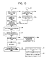
- a block signal selection unit 42 may be used instead of using the block signal addition unit 41 , as illustrated in FIG. 13 .
- the block signal selection unit 42 executes processing for discarding the signal of the overlap instead of executing the above-mentioned processing for coherently adding the signal of the overlap. With this configuration, it is possible to reduce processing load by an amount corresponding to the addition processing that is not executed.
- the block-by-block Doppler processing unit sets the blocks so that the adjacent blocks overlap each other, to thereby set the bandwidth of the Doppler frequency spectrum in the block-direction Doppler processing performed by the block-direction Doppler processing unit wider than the bandwidth of each Doppler filter obtained as a result of the Doppler processing performed by the block-by-block Doppler processing unit.
Landscapes
- Engineering & Computer Science (AREA)
- Radar, Positioning & Navigation (AREA)
- Remote Sensing (AREA)
- Computer Networks & Wireless Communication (AREA)
- Physics & Mathematics (AREA)
- General Physics & Mathematics (AREA)
- Radar Systems Or Details Thereof (AREA)
Abstract
Description
- [PTL 1] JP 08-179037 A
- [PTL 2] JP 2006-258786 A
- [PTL 3] JP 2009-270827 A
- [NPL 1] N. J. Willis and H. D. Griffiths, “Advances in Bistatic Radar”, Scitech publishing Inc., 2007
- [NPL 2] K. S. Kulpa, J. Misiurewicz, “Stretch Processing for Long Integration Time Passive Covert Radar”, International Conference on Radar, 2006
- [NPL 3] M. admard, H. Habibi, M. H. Bastani, F. Behnia, “Target's range migration compensation in passive radar”, European Radar Conference, 2009. EuRAD 2009
[Math. 3]
T=HTb
Tb=NT0 (3)
[Math. 4]
{tilde over (s)} d(t)=a(t−τ d)exp{j2πf c(t−τ d)} (4)
[Math. 5]
{tilde over (s)} dn(t)=a(t−τ d)exp{j2πf c(t−τ d)} (t n −T 0/2≦t≦t n +T 0/2) (5)
[Math. 6]
τsn=τsn0+{dot over (τ)}sn(t−t n) (6)
[Math. 15]
x n(τ)=∫t
[Math. 16]
x n(τ)=α exp{−j2π(f cτn −Δf c τ+f dn t n)}∫t
[Math. 17]
R a(τ)=E{a(t)a*(t−τ)} (17)
[Math. 22]
{hacek over (x)} n,h(τ)(n=0,1, . . . ,N−1; h=0,1, . . . ,H−1) (22)
[Math. 26]
fdn=fd (26)
[Math. 32]
Y h(f,f dm)=
[Math. 35]
{hacek over (y)} h(τ,f dm)=
[Math. 42]
P(τ,f dm ,f dl)=|z(τ,f dm ,f dl)|2 (41)
Claims (15)
Applications Claiming Priority (1)
| Application Number | Priority Date | Filing Date | Title |
|---|---|---|---|
| PCT/JP2011/053500 WO2012111141A1 (en) | 2011-02-18 | 2011-02-18 | Passive radar device |
Publications (2)
| Publication Number | Publication Date |
|---|---|
| US20130321199A1 US20130321199A1 (en) | 2013-12-05 |
| US9400323B2 true US9400323B2 (en) | 2016-07-26 |
Family
ID=46672102
Family Applications (1)
| Application Number | Title | Priority Date | Filing Date |
|---|---|---|---|
| US13/984,936 Expired - Fee Related US9400323B2 (en) | 2011-02-18 | 2011-02-18 | Passive radar device |
Country Status (4)
| Country | Link |
|---|---|
| US (1) | US9400323B2 (en) |
| EP (1) | EP2677343B1 (en) |
| JP (1) | JP5665893B2 (en) |
| WO (1) | WO2012111141A1 (en) |
Cited By (1)
| Publication number | Priority date | Publication date | Assignee | Title |
|---|---|---|---|---|
| US10416277B2 (en) * | 2014-04-21 | 2019-09-17 | Mitsubishi Electric Corporation | Positioning device |
Families Citing this family (25)
| Publication number | Priority date | Publication date | Assignee | Title |
|---|---|---|---|---|
| JP5514156B2 (en) * | 2011-06-06 | 2014-06-04 | 株式会社東芝 | Radar apparatus and received data processing method |
| GB201204792D0 (en) * | 2012-03-19 | 2012-05-02 | Qinetiq Ltd | Detection techniques |
| JP5865794B2 (en) * | 2012-07-13 | 2016-02-17 | 三菱電機株式会社 | Radar equipment |
| WO2014092052A1 (en) * | 2012-12-14 | 2014-06-19 | 三菱電機株式会社 | Radar apparatus |
| JPWO2014128995A1 (en) * | 2013-02-25 | 2017-02-02 | 三菱電機株式会社 | Passive radar device |
| CN103197284B (en) * | 2013-03-21 | 2015-02-25 | 北京理工大学 | Radar wave form design method restrained by autocorrelation, orthogonality and Doppler tolerance |
| DK2950116T3 (en) * | 2014-05-28 | 2019-06-24 | Diehl Defence Gmbh & Co Kg | PROCEDURE FOR DETERMINING IN THE LOWEST ATTENTION OF AN AIRPORT AND / OR IN THE MINIMUM OF A PROPERTY AT THE OBJECT AND THE ORDERED DETECTOR DETECTOR |
| CN104062640B (en) * | 2014-06-30 | 2016-03-30 | 北京理工大学 | The Fast implementation that a kind of external illuminators-based radar range migration compensates |
| US9746549B1 (en) * | 2014-07-11 | 2017-08-29 | Altera Corporation | Constant false alarm rate circuitry in adaptive target detection of radar systems |
| US9715009B1 (en) * | 2014-12-19 | 2017-07-25 | Xidrone Systems, Inc. | Deterent for unmanned aerial systems |
| CN104714213A (en) * | 2015-03-30 | 2015-06-17 | 宁波高新区宁源科技服务有限公司 | Migration compensation method based on multiple sampling rates and speed channel division |
| KR102404891B1 (en) * | 2015-12-23 | 2022-06-07 | 주식회사 에이치엘클레무브 | Method for detecting target object and apparatus thereof |
| CN105785331B (en) * | 2016-03-02 | 2018-05-29 | 河海大学 | A kind of external illuminators-based radar direct wave restoration methods using blind source separating |
| CN106597409B (en) * | 2016-12-19 | 2019-02-12 | 电子科技大学 | A kind of delay-Doppler frequency displacement extracting method based on external illuminators-based radar |
| AU2018265772B2 (en) | 2017-05-12 | 2022-06-09 | Locata Corporation Pty Ltd | Methods and apparatus for characterising the environment of a user platform |
| WO2018220825A1 (en) * | 2017-06-02 | 2018-12-06 | 三菱電機株式会社 | Radar device |
| EP3483629B1 (en) * | 2017-11-09 | 2021-12-29 | Veoneer Sweden AB | Detecting a parking row with a vehicle radar system |
| EP3721255A2 (en) * | 2017-12-05 | 2020-10-14 | FCS Flight Calibration Services GmbH | Method for passively measuring electromagnetic reflection properties of scattering bodies and method for producing at least one artificial target for a monostatic, rotating radar through a floating platform |
| CN108919208A (en) * | 2018-04-03 | 2018-11-30 | 芜湖泰贺知信息系统有限公司 | A kind of passive radar reference signal acquisition methods based on reflection |
| CN110018445A (en) * | 2019-03-29 | 2019-07-16 | 南京理工大学 | A kind of active and passive electromagnetic environment cognitive method combined |
| CN110109091B (en) * | 2019-05-23 | 2021-11-09 | 中国人民解放军战略支援部队信息工程大学 | Passive radar parameter estimation method and device for high-speed target |
| CN113325363A (en) * | 2020-02-28 | 2021-08-31 | 加特兰微电子科技(上海)有限公司 | Method and device for determining direction of arrival and related equipment |
| CN113219458B (en) * | 2021-05-26 | 2022-05-03 | 电子科技大学 | Bistatic synthetic aperture radar blind positioning method |
| CN113534113B (en) * | 2021-05-31 | 2023-08-15 | 中国船舶重工集团公司第七一五研究所 | Sonar target line spectrum enhancement method based on motion compensation |
| CN113655459B (en) * | 2021-09-27 | 2024-04-26 | 清华大学 | Radar non-fuzzy Doppler expansion method and device based on poisson disk sampling |
Citations (9)
| Publication number | Priority date | Publication date | Assignee | Title |
|---|---|---|---|---|
| US5250952A (en) * | 1991-07-01 | 1993-10-05 | Duane Roth | Method of correcting rotational motion error in SAR and ISAR imagery |
| JPH08179037A (en) | 1994-12-22 | 1996-07-12 | Mitsubishi Electric Corp | Radar device |
| JP2000147113A (en) | 1998-11-12 | 2000-05-26 | Mitsubishi Electric Corp | Synthetic aperture radar signal processor |
| US20040233105A1 (en) * | 2001-05-04 | 2004-11-25 | Lockheed Martin Corporation | System and method for central association and tracking in passive coherent location applications |
| US20040257270A1 (en) * | 2001-12-26 | 2004-12-23 | Dominique Poullin | Clutter rejection in a passive radar receiver of ofdm signals with antenna array |
| US20050285787A1 (en) * | 2003-07-25 | 2005-12-29 | Thales | Method for multistatic detection and locating of a mobile craft through the use of digital broadcasting transmitters |
| JP2006258786A (en) | 2005-02-15 | 2006-09-28 | Mitsubishi Electric Corp | Radar installation |
| JP2009270827A (en) | 2008-04-30 | 2009-11-19 | Mitsubishi Electric Corp | Multi-static radar system |
| US20100097266A1 (en) * | 2008-10-21 | 2010-04-22 | Lockheed Martin Corporation | Single platform passive coherent location using a digital receiver |
-
2011
- 2011-02-18 EP EP11858756.7A patent/EP2677343B1/en active Active
- 2011-02-18 JP JP2012557754A patent/JP5665893B2/en not_active Expired - Fee Related
- 2011-02-18 US US13/984,936 patent/US9400323B2/en not_active Expired - Fee Related
- 2011-02-18 WO PCT/JP2011/053500 patent/WO2012111141A1/en active Application Filing
Patent Citations (9)
| Publication number | Priority date | Publication date | Assignee | Title |
|---|---|---|---|---|
| US5250952A (en) * | 1991-07-01 | 1993-10-05 | Duane Roth | Method of correcting rotational motion error in SAR and ISAR imagery |
| JPH08179037A (en) | 1994-12-22 | 1996-07-12 | Mitsubishi Electric Corp | Radar device |
| JP2000147113A (en) | 1998-11-12 | 2000-05-26 | Mitsubishi Electric Corp | Synthetic aperture radar signal processor |
| US20040233105A1 (en) * | 2001-05-04 | 2004-11-25 | Lockheed Martin Corporation | System and method for central association and tracking in passive coherent location applications |
| US20040257270A1 (en) * | 2001-12-26 | 2004-12-23 | Dominique Poullin | Clutter rejection in a passive radar receiver of ofdm signals with antenna array |
| US20050285787A1 (en) * | 2003-07-25 | 2005-12-29 | Thales | Method for multistatic detection and locating of a mobile craft through the use of digital broadcasting transmitters |
| JP2006258786A (en) | 2005-02-15 | 2006-09-28 | Mitsubishi Electric Corp | Radar installation |
| JP2009270827A (en) | 2008-04-30 | 2009-11-19 | Mitsubishi Electric Corp | Multi-static radar system |
| US20100097266A1 (en) * | 2008-10-21 | 2010-04-22 | Lockheed Martin Corporation | Single platform passive coherent location using a digital receiver |
Non-Patent Citations (11)
| Title |
|---|
| Extended European Search Report issued on Jan. 22, 2015 in Application No. 11858756.7. |
| International Search Report issued May 24, 2011 in PCT/JP2011/053500. |
| Kazuhiko Yamamoto, et al., "A New Phase Compensation Algorithm for a Doppler Radar Imaging", The Transactions of the Institute of Electronics, Information and Communication Engineers, Oct. 25, 2000, vol. J83-B, No. 10, pp. 1453-1461. |
| Kei Suwa, et al., "ISAR Imaging of an Aircraft Target Using ISDB-T Digital TV Based Passive Bistatic Radar", Geoscience and Remote Sensing Symposium (IGARSS), 2010 IEEE International, XP031811646, Jul. 25, 2010, pp. 4103-4105. |
| Kei Suwa, et al., "Passive ISAR Imaging Using the Digital Terrestrial Television Signals-The Algorithm", Proceedings of the 2010 IEICE General Conference Tsushin 1, Mar. 2, 2010, p. 312. |
| Krzysztof S. Kulpa, et al., "Stretch Processing for Long Integration Time Passive Covert Radar", International Conference on Radar, CIE '06, 2006, 4 pages. |
| Kulpa, K.S.; Misiurewicz, J., "Stretch Processing for Long Integration Time Passive Covert Radar," Radar, 2006. CIE '06. International Conference on , vol., No., pp. 1,4, Oct. 16-19, 2006. * |
| M. Radmard, et al., "Target's Range Migration Compensation in Passive Radar", Proceedings of the 6th European Radar Conferences, 2009, pp. 457-460. |
| Nicholas J. Willis, et al., "Advances in Bistatic Radar", SciTech Publishing Inc., 2007, pp. 78-104. |
| Suwa, K.; Nakamura, S.; Morita, S.; Wakayama, T.; Maniwa, H.; Oshima, T.; Maekawa, R.; Matsuda, S.; Tachihara, T., "ISAR imaging of an aircraft target Using ISDB-T digital TV based passive bistatic radar," Geoscience and Remote Sensing Symposium (IGARSS), 2010 IEEE International , vol., No., pp. 4103,4105, Jul. 25-30, 2010. * |
| Zhang Fenghui, et al., "A New Real Time Range-Doppler Imaging Algorithm", Systems and Control in Aeronautics and Astronautics (ISSCAA), 2010 3rd International Symposium on, IEEE, XP031799688, Jun. 8, 2010, pp. 119-122. |
Cited By (1)
| Publication number | Priority date | Publication date | Assignee | Title |
|---|---|---|---|---|
| US10416277B2 (en) * | 2014-04-21 | 2019-09-17 | Mitsubishi Electric Corporation | Positioning device |
Also Published As
| Publication number | Publication date |
|---|---|
| JPWO2012111141A1 (en) | 2014-07-03 |
| JP5665893B2 (en) | 2015-02-04 |
| US20130321199A1 (en) | 2013-12-05 |
| EP2677343A1 (en) | 2013-12-25 |
| EP2677343B1 (en) | 2021-03-24 |
| WO2012111141A1 (en) | 2012-08-23 |
| EP2677343A4 (en) | 2015-02-25 |
Similar Documents
| Publication | Publication Date | Title |
|---|---|---|
| US9400323B2 (en) | Passive radar device | |
| US11656325B2 (en) | Methods and apparatus to realize scalable antenna arrays with large aperture | |
| JP4496954B2 (en) | Interferometric radar | |
| US10024958B2 (en) | Radar apparatus | |
| US9500741B2 (en) | Radar apparatus | |
| JP5606097B2 (en) | Passive radar device | |
| EP2960675A1 (en) | Passive radar device | |
| US10228459B2 (en) | Radar system and radar signal processing device | |
| JP5865794B2 (en) | Radar equipment | |
| US20080048906A1 (en) | Electronic scanning radar apparatus | |
| JP2006308285A (en) | Interference radar | |
| JP2012103203A (en) | Fmcw radar device | |
| JP5823062B2 (en) | Radar equipment | |
| EP3771921A1 (en) | Method for processing non-interrupted phase synchronization signal of bistatic sar based on coded signal | |
| JP6324327B2 (en) | Passive radar equipment | |
| EP3399334B1 (en) | Object detecting device and sensor device | |
| JP2010175457A (en) | Radar apparatus | |
| JP2010286404A (en) | Moving target detector | |
| Anghel et al. | Simplified bistatic SAR imaging with a fixed receiver and TerraSAR-X as transmitter of opportunity-First results | |
| JP6573748B2 (en) | Radar equipment | |
| JP2006145251A (en) | Radio wave arrival direction prediction system | |
| JP2015036628A (en) | Passive radar device | |
| Lee | Target Velocity Estimation using FFT Method | |
| Sanyuan et al. | Time synchronisation error correction for BiSAR using phase history of direct-path signal |
Legal Events
| Date | Code | Title | Description |
|---|---|---|---|
| AS | Assignment |
Owner name: MITSUBISHI ELECTRIC CORPORATION, JAPAN Free format text: ASSIGNMENT OF ASSIGNORS INTEREST;ASSIGNORS:SUWA, KEI;OSHIMA, TADASHI;NAKAMURA, SHOHEI;AND OTHERS;SIGNING DATES FROM 20130702 TO 20130703;REEL/FRAME:030989/0305 |
|
| STCF | Information on status: patent grant |
Free format text: PATENTED CASE |
|
| FEPP | Fee payment procedure |
Free format text: MAINTENANCE FEE REMINDER MAILED (ORIGINAL EVENT CODE: REM.); ENTITY STATUS OF PATENT OWNER: LARGE ENTITY |
|
| LAPS | Lapse for failure to pay maintenance fees |
Free format text: PATENT EXPIRED FOR FAILURE TO PAY MAINTENANCE FEES (ORIGINAL EVENT CODE: EXP.); ENTITY STATUS OF PATENT OWNER: LARGE ENTITY |
|
| STCH | Information on status: patent discontinuation |
Free format text: PATENT EXPIRED DUE TO NONPAYMENT OF MAINTENANCE FEES UNDER 37 CFR 1.362 |
|
| FP | Lapsed due to failure to pay maintenance fee |
Effective date: 20200726 |