US9391663B2 - Flip cover plate for mobile terminal - Google Patents
Flip cover plate for mobile terminal Download PDFInfo
- Publication number
- US9391663B2 US9391663B2 US14/433,034 US201314433034A US9391663B2 US 9391663 B2 US9391663 B2 US 9391663B2 US 201314433034 A US201314433034 A US 201314433034A US 9391663 B2 US9391663 B2 US 9391663B2
- Authority
- US
- United States
- Prior art keywords
- cover plate
- transparent window
- flip cover
- mobile terminal
- flip
- Prior art date
- Legal status (The legal status is an assumption and is not a legal conclusion. Google has not performed a legal analysis and makes no representation as to the accuracy of the status listed.)
- Active
Links
- 239000004973 liquid crystal related substance Substances 0.000 claims abstract description 4
- 239000011248 coating agent Substances 0.000 claims description 37
- 238000000576 coating method Methods 0.000 claims description 37
- 230000003014 reinforcing effect Effects 0.000 claims description 35
- 239000000463 material Substances 0.000 claims description 14
- VYPSYNLAJGMNEJ-UHFFFAOYSA-N Silicium dioxide Chemical compound O=[Si]=O VYPSYNLAJGMNEJ-UHFFFAOYSA-N 0.000 claims description 12
- 238000001746 injection moulding Methods 0.000 claims description 12
- 239000011247 coating layer Substances 0.000 claims description 6
- 230000001681 protective effect Effects 0.000 claims description 6
- 239000000377 silicon dioxide Substances 0.000 claims description 6
- 239000012780 transparent material Substances 0.000 claims description 6
- 239000012790 adhesive layer Substances 0.000 claims description 4
- 230000006835 compression Effects 0.000 claims description 3
- 238000007906 compression Methods 0.000 claims description 3
- 229910052681 coesite Inorganic materials 0.000 claims 1
- 229910052906 cristobalite Inorganic materials 0.000 claims 1
- 229910052682 stishovite Inorganic materials 0.000 claims 1
- 229910052905 tridymite Inorganic materials 0.000 claims 1
- 238000004519 manufacturing process Methods 0.000 abstract description 22
- 238000005520 cutting process Methods 0.000 abstract description 5
- 238000012545 processing Methods 0.000 description 8
- 230000007547 defect Effects 0.000 description 7
- 238000000034 method Methods 0.000 description 7
- 229920000515 polycarbonate Polymers 0.000 description 6
- 239000004417 polycarbonate Substances 0.000 description 6
- 239000005020 polyethylene terephthalate Substances 0.000 description 6
- 229920000139 polyethylene terephthalate Polymers 0.000 description 6
- 239000000853 adhesive Substances 0.000 description 5
- 230000001070 adhesive effect Effects 0.000 description 5
- XJHCXCQVJFPJIK-UHFFFAOYSA-M caesium fluoride Chemical compound [F-].[Cs+] XJHCXCQVJFPJIK-UHFFFAOYSA-M 0.000 description 4
- 229920005989 resin Polymers 0.000 description 4
- 239000011347 resin Substances 0.000 description 4
- 230000002708 enhancing effect Effects 0.000 description 3
- 239000010410 layer Substances 0.000 description 3
- MCMNRKCIXSYSNV-UHFFFAOYSA-N ZrO2 Inorganic materials O=[Zr]=O MCMNRKCIXSYSNV-UHFFFAOYSA-N 0.000 description 2
- 230000003247 decreasing effect Effects 0.000 description 2
- 238000000151 deposition Methods 0.000 description 2
- -1 e.g. Substances 0.000 description 2
- 238000002347 injection Methods 0.000 description 2
- 239000007924 injection Substances 0.000 description 2
- 229910010272 inorganic material Inorganic materials 0.000 description 2
- 239000011147 inorganic material Substances 0.000 description 2
- 238000005259 measurement Methods 0.000 description 2
- RVTZCBVAJQQJTK-UHFFFAOYSA-N oxygen(2-);zirconium(4+) Chemical compound [O-2].[O-2].[Zr+4] RVTZCBVAJQQJTK-UHFFFAOYSA-N 0.000 description 2
- 235000012239 silicon dioxide Nutrition 0.000 description 2
- 239000007779 soft material Substances 0.000 description 2
- 241001061260 Emmelichthys struhsakeri Species 0.000 description 1
- YCKRFDGAMUMZLT-UHFFFAOYSA-N Fluorine atom Chemical compound [F] YCKRFDGAMUMZLT-UHFFFAOYSA-N 0.000 description 1
- NIXOWILDQLNWCW-UHFFFAOYSA-N acrylic acid group Chemical group C(C=C)(=O)O NIXOWILDQLNWCW-UHFFFAOYSA-N 0.000 description 1
- 239000000956 alloy Substances 0.000 description 1
- 229910045601 alloy Inorganic materials 0.000 description 1
- 239000012141 concentrate Substances 0.000 description 1
- 238000007796 conventional method Methods 0.000 description 1
- 230000008878 coupling Effects 0.000 description 1
- 238000010168 coupling process Methods 0.000 description 1
- 238000005859 coupling reaction Methods 0.000 description 1
- 238000011161 development Methods 0.000 description 1
- 239000000428 dust Substances 0.000 description 1
- 238000005516 engineering process Methods 0.000 description 1
- VJYFKVYYMZPMAB-UHFFFAOYSA-N ethoprophos Chemical compound CCCSP(=O)(OCC)SCCC VJYFKVYYMZPMAB-UHFFFAOYSA-N 0.000 description 1
- 238000007667 floating Methods 0.000 description 1
- 229910052731 fluorine Inorganic materials 0.000 description 1
- 239000011737 fluorine Substances 0.000 description 1
- 239000011521 glass Substances 0.000 description 1
- 229910001635 magnesium fluoride Inorganic materials 0.000 description 1
- 239000011368 organic material Substances 0.000 description 1
- 239000003973 paint Substances 0.000 description 1
- 229920005668 polycarbonate resin Polymers 0.000 description 1
- 239000004431 polycarbonate resin Substances 0.000 description 1
- 238000000926 separation method Methods 0.000 description 1
- 238000002834 transmittance Methods 0.000 description 1
Images


Classifications
-
- A—HUMAN NECESSITIES
- A45—HAND OR TRAVELLING ARTICLES
- A45C—PURSES; LUGGAGE; HAND CARRIED BAGS
- A45C11/00—Receptacles for purposes not provided for in groups A45C1/00-A45C9/00
-
- H—ELECTRICITY
- H04—ELECTRIC COMMUNICATION TECHNIQUE
- H04B—TRANSMISSION
- H04B1/00—Details of transmission systems, not covered by a single one of groups H04B3/00 - H04B13/00; Details of transmission systems not characterised by the medium used for transmission
- H04B1/38—Transceivers, i.e. devices in which transmitter and receiver form a structural unit and in which at least one part is used for functions of transmitting and receiving
- H04B1/3827—Portable transceivers
- H04B1/3888—Arrangements for carrying or protecting transceivers
-
- A—HUMAN NECESSITIES
- A45—HAND OR TRAVELLING ARTICLES
- A45C—PURSES; LUGGAGE; HAND CARRIED BAGS
- A45C13/00—Details; Accessories
- A45C13/002—Protective covers
-
- H—ELECTRICITY
- H04—ELECTRIC COMMUNICATION TECHNIQUE
- H04M—TELEPHONIC COMMUNICATION
- H04M1/00—Substation equipment, e.g. for use by subscribers
- H04M1/02—Constructional features of telephone sets
- H04M1/0202—Portable telephone sets, e.g. cordless phones, mobile phones or bar type handsets
-
- H—ELECTRICITY
- H04—ELECTRIC COMMUNICATION TECHNIQUE
- H04M—TELEPHONIC COMMUNICATION
- H04M1/00—Substation equipment, e.g. for use by subscribers
- H04M1/02—Constructional features of telephone sets
- H04M1/18—Telephone sets specially adapted for use in ships, mines, or other places exposed to adverse environment
- H04M1/185—Improving the shock resistance of the housing, e.g. by increasing the rigidity
-
- A—HUMAN NECESSITIES
- A45—HAND OR TRAVELLING ARTICLES
- A45C—PURSES; LUGGAGE; HAND CARRIED BAGS
- A45C11/00—Receptacles for purposes not provided for in groups A45C1/00-A45C9/00
- A45C11/002—Receptacles for purposes not provided for in groups A45C1/00-A45C9/00 for storing portable handheld communication devices, e.g. pagers or smart phones
-
- A—HUMAN NECESSITIES
- A45—HAND OR TRAVELLING ARTICLES
- A45C—PURSES; LUGGAGE; HAND CARRIED BAGS
- A45C2200/00—Details not otherwise provided for in A45C
- A45C2200/05—Means for indicating features of the content from outside
-
- A—HUMAN NECESSITIES
- A45—HAND OR TRAVELLING ARTICLES
- A45C—PURSES; LUGGAGE; HAND CARRIED BAGS
- A45C2200/00—Details not otherwise provided for in A45C
- A45C2200/10—Transparent walls
-
- H—ELECTRICITY
- H04—ELECTRIC COMMUNICATION TECHNIQUE
- H04M—TELEPHONIC COMMUNICATION
- H04M1/00—Substation equipment, e.g. for use by subscribers
- H04M1/02—Constructional features of telephone sets
- H04M1/0202—Portable telephone sets, e.g. cordless phones, mobile phones or bar type handsets
- H04M1/0206—Portable telephones comprising a plurality of mechanically joined movable body parts, e.g. hinged housings
- H04M1/0208—Portable telephones comprising a plurality of mechanically joined movable body parts, e.g. hinged housings characterized by the relative motions of the body parts
- H04M1/0214—Foldable telephones, i.e. with body parts pivoting to an open position around an axis parallel to the plane they define in closed position
Definitions
- the present invention relates to a flip cover plate for a mobile terminal, in which an injection molding process, instead of conventional individual processing through a machine tool, is applied to a cover plate, and a transparent window is separately formed and attached to the cover plate, thus leading to reduced manufacture costs for flip cover plates, maximized productability, and increased product reliability.
- smartphones equipped with various functions are selling expensive, and accordingly, protective cases are gaining popularity to protect the phones.
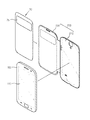
- a protection case typically includes a case body 210 covering the rear and side surfaces of a mobile phone 100 thereof and a flip cover 220 rotatably coupled with the case body 210 at a side thereof to open and close the front surface of the mobile phone 100 .
- a cover plate 30 is placed inside the flip cover 220 to maintain the shape of the flip cover 220 and to protect the front surface 110 of the mobile phone 100 .
- Such cover plate has been conventionally manufactured by performing individual processing on a material, e.g., polycarbonate resin, using a machine tool, such as a numerically controlled (NC) machine.
- a machine tool such as a numerically controlled (NC) machine.
- cover plate is done individually, i.e., unit-by-unit, resulting in low production efficiency and increased manufacture costs.
- an object of the present invention is to provide a flip cover plate for a mobile terminal which is formed in a manner of attaching a transparent window onto a cover plate to remarkably reduce processing time and costs as compared with conventional numerically controlled machine tools and minimize defect rate by eliminating the likelihood that an errors occurs depending on the worker's skill, thus enhancing product reliability.
- Another object of the present invention is to provide a flip cover plate for a mobile terminal with a transparent window formed using a separate hard coating film, presenting an enhanced surface hardness and strength, thus preventing damage that may occur upon the user's touch to provide more stable performance.
- flip cover plate for a mobile terminal comprising: a cover plate inserted in a flip cover opening and closing a front surface of the mobile terminal; and a transparent window coupled at a side of the cover plate to externally expose part of a liquid crystal display of the mobile terminal while the flip cover is positioned on the front surface of the mobile terminal, wherein the transparent window is formed by attaching the same onto at least one surface of the cover plate corresponding to an opening of the flip cover.
- the cover plate may have a seating hole where the transparent window is seated, and the transparent window may be formed by injection-molding a transparent material and is then attached at the seating hole.
- the transparent window may have a bonding part around an edge thereof, and a bonding groove corresponding to the bonding part may be formed in the seating hole to guide the transparent window to be seated while the bonding part and the bonding groove, engaged with each other, are simultaneously bonded by an ultrasonic wave or heat.
- the transparent window may include as base film, an adhesive layer formed on a side surface of the base film, facing the cover plate, a hardness reinforcing coating layer formed on another side surface of the base film, and a protective film formed on the hardness reinforcing coating layer.
- the transparent window may be formed by wet-coating SiO 2 on a surface of the cover plate.
- the transparent window may be formed by attaching as hard coating film on a surface of the cover plate using an OCA.
- the transparent window may be formed by sequentially stacking and attaching the hard coating film and one or more reinforcing films on a surface of the cover plate.
- the cover plate may be formed through an injection molding process.
- the base film may be formed of PET or PC.
- the transparent window is preferably formed to be coplanar with a surface of the flip cover.
- a reinforcing member may be further formed in the cover plate adjacent to the transparent window to prevent a local deformation due to a warp of the cover plate and to prevent the transparent window from escaping.
- the reinforcing member may be formed in the cover plate corresponding to each of both ends of the transparent window, and the reinforcing member may be formed of a reinforcing pin with a longitudinal direction in a direction in which the cover plate warps.
- the reinforcing pin may be inserted and fixed in the cover plate by thermal compression.
- the transparent window may contain a material with a dielectric constant to allow for a touch input while the flip cover is positioned on the front surface.
- the present invention may remarkably reduce processing time and costs as compared with conventional numerically controlled machine tools and minimize defect rate by eliminating the likelihood that an errors occurs depending on the worker's skill, thus enhancing product reliability.
- the present invention may maximize productability as compared with conventional methods of manufacturing products by performing individual cutting processes using a NC machine.
- the transparent window is not simultaneously formed, and thus, the molds may be simplified in shape, thus reducing manufacture costs. Further, production of parts proceeds in parallel, leading to further shortened production time along with a decreased defect rate.
- a reinforcing member is provided on a side of the transparent window, preventing a deformation of the cover plate or detachment of the transparent window due to a warp.
- the transparent window may be formed by attaching a hard coating film, thus leading to easier manufacture of the flip cover plate, reduced manufacture time and costs, and enhanced measurement accuracy, along with a reduced defect rate.
- the transparent window may be formed using a separate hard coating film, presenting an enhanced surface hardness and strength and resultantly preventing damage that may occur upon the user's touch to provide more stable performance.
- the transparent window may be formed by sequentially stacking and attaching a hard coating film and a separate reinforcing film, thus reducing the slight deformation of the hard coating film that may occur when the user touches for manipulation to prevent damage to the hard coating film. Accordingly, further increased durability may be achieved.
- FIGS. 1 and 2 are views illustrating an example of putting in a flip cover plate for a mobile terminal according to an embodiment of the present invention.
- FIG. 3 is a perspective view illustrating a flip cover plate for a mobile terminal according to a first embodiment of the present invention.
- FIG. 4 is a cross-sectional view illustrating a flip cover plate for a mobile terminal according to a second embodiment of the present invention.
- FIG. 5 is a cross-sectional view illustrating a flip cover plate for a mobile terminal according to an embodiment of the present invention.
- FIG. 6 is a view schematically illustrating the shape of an inner film of a mobile phone case according to a third embodiment of the present invention.
- FIGS. 7 and 8 are magnified views each illustrating the structure of a transparent touch part of an inner plate according to the third embodiment of the present invention.
- FIG. 9 is a magnified view illustrating the structure of a transparent touch part according to another embodiment of the present invention.
- a tube connection part 10 for a mobile terminal includes a cover plate 30 inserted in a flip cover 220 opening and closing a front surface 110 of a mobile terminal 100 and a transparent window 35 coupled at a side of the cover plate 30 to partially expose the liquid crystal display (LCD) of the mobile terminal 100 while the flip cover 220 is positioned on the front surface of the mobile terminal 100 .
- the transparent window 35 is formed in such a manner that the transparent window 35 is attached onto at least one surface of the cover plate 30 corresponding to an opening of the flip cover 220 .
- the transparent window 35 may be prepared by various methods, and each embodiment is hereinafter described in detail.
- the transparent window 35 is formed by performing an injection molding process on a transparent material, and is then attached to the cover plate 30 .
- the cover plate 30 is placed in the flip cover 220 opening and closing the front surface 110 of the mobile terminal 100 , as shown in FIG. 1 .
- the flip cover 220 is rotatably coupled to the case body 210 coupled with the mobile terminal 100 at a rear surface and site surfaces thereof.
- the cover plate 30 according to the present invention is preferably manufactured by an injection molding method as proposed in the Applicant's prior patent application, Korean Patent Application No. 2013-0060963.
- the present invention may maximize productability.
- the transparent window 35 is not simultaneously formed upon injecting the cover plate 30 , and thus, the molds may be simplified in shape, thus reducing manufacture costs and the defect rate of products.
- the cover plate 30 may be formed of various materials, preferably polycarbonate (PC) or a light transmissive material obtained by mixing polycarbonate and a glass material.
- PC polycarbonate
- a light transmissive material obtained by mixing polycarbonate and a glass material.
- a seating hole 31 guides the transparent window to be seated.
- the seating hole 31 is formed at a side of the cover plate 30 as shown in FIG. 3 and guides the coupling position of the transparent window 35 .
- the transparent window 35 is coupled at a side of the cover plate 30 to partially expose the LCD of the mobile terminal 100 to the outside while the flip cover 220 is positioned on the front surface 110 of the mobile terminal 100 .
- the transparent window 35 is configured to alloy the user to check time or information on callers even without opening the flip cover 220 , thus maximizing user convenience.
- the transparent window 35 may be prepared in various manners.
- the transparent window 35 may be formed by injection molding and may be attached, or as shown in FIG. 4 , the transparent window 35 may be formed by stacking multiple films and may be attached.
- the transparent window 35 may be formed by performing injection molding on a transparent material.
- the transparent window 35 may be formed of various materials, preferably an acrylic material for enhancing light transmittance.
- the transparent window 35 may be attached to the cover plate 30 by various methods.
- the transparent window 35 may be attached to the cover plate 30 by an adhesive or by an ultrasonic or thermal bonding.
- a bonding part 351 may be formed around the edge of the transparent window 35 , a bonding groove 311 may be formed in the seating hole 31 , corresponding to the bonding part 351 .
- the bonding part 351 and the bonding groove 311 engaged with each other may be bonded by heat or ultrasonic wave.
- a reinforcing member 40 may be further formed in the cover plate 30 adjacent to the transparent window 35 to prevent the cover plate 30 from locally deforming due to a warp and to prevent the transparent window 35 from escaping.
- the cover plate 30 and the transparent window 35 are formed as a single body.
- the flip cover 220 may remain deformed without turning back to its original shape, or the transparent window 35 may be spaced apart from the cover plate 30 causing a floating or separation.
- the reinforcing member 40 formed as shown in FIG. 5 may prevent the cover plate 30 from remaining deformed or prevent the transparent window 35 from escaping.
- reinforcing members 40 may be provided.
- reinforcing members 40 may be reinforcing pins that are respectively formed at both ends of the transparent window 35 and whose longitudinal direction corresponds to the direction in which the cover plate 30 is warped.
- the reinforcing pins may be inserted and fixed in the rover plate 30 by thermal compression.
- the transparent window may contain a material with a dielectric constant to allow for a touch input while the flip cover is positioned on the front surface.
- the transparent window 35 is formed by stacking multiple films including a base film 355 .
- the transparent window 35 may be provided with multiple film layers and may be attached onto the cover plate 30 .
- the transparent window 35 may include the base film 355 , an adhesive layer 356 formed on a side surface of the base film 355 , facing the cover plate 30 , a hardness reinforcing coating layer 357 formed on the other side surface of the base film 355 , and a protective film 358 formed on the hardness reinforcing coating layer 357 .
- the base film 355 may be formed of polyethylene terephthalate (PET), and the adhesive layer 356 may be formed of an optically clear adhesive (OCA).
- PET polyethylene terephthalate
- OCA optically clear adhesive
- the transparent window 35 is attached on to surface of the cover plate 30 by a hard coating film 359 .
- a case 200 includes a case body 210 covering a rear surface and sick surfaces of the mobile terminal 100 , a flip cover 220 rotatably provided on a side of the case body 210 to open and close the front surface 110 of the mobile terminal 100 , and a cover plate 30 inserted in the flip cover 220 .
- the case body 210 is formed to have an opening at a surface thereof to provide a space for accommodating the mobile terminal 100 , and the flip cover 220 is coupled to the case body 210 via a soft material to be rotatable.
- the flip cover 220 rotates about the case body 210 to open and close the front surface 110 of the mobile terminal 100 accommodated in the case body 210 . That is, the flip cover 220 externally exposes or blocks and protects the front surface of the mobile terminal 100 from the outside.
- the flip cover 220 rotates to block the front surface 110 of the mobile terminal 100 from the outside and contacts the front surface 110 of the mobile terminal 100 . Accordingly, the flip cover 220 is formed of as soft material not to damage the touch panel and display screen formed on the front surface 110 of the mobile terminal 100 . Thus, the plate-shaped cover plate 30 is placed in the flip cover 220 to allow the structure a strength.
- the flip cover 220 has an opening 211 at a side thereof, allowing part of the display screen formed on the front surface 110 of the mobile terminal 100 to be viewed from outside, and the transparent window 35 is formed in the cover plate 30 to be externally exposed through the opening 211 .
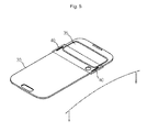
- the inner surface of the transparent window 35 comes in contact with the front surface 110 of the mobile terminal 100 , and thus, the transparent window 35 is formed coplanar with the surface of the flip cover 220 as shown in FIG. 6 .
- the transparent window 35 is formed on the surface of the cover plate 30 at the same thickness as a height of the case surface so that no step may be formed between the region where the opening 211 is formed and the surface of the flip cover 220 . Accordingly, it is preferable to form the transparent window 35 on each of both surfaces of the cover plate 30 from a perspective of arrangement. Of course, as necessary, the transparent window 35 may be formed only on one surface of the cover plate 30 .
- the transparent window 35 is formed to allow the display screen formed on the front surface 110 of the mobile terminal 100 to be viewed from outside as well as to allow the front surface 110 of the mobile terminal 100 to be manipulated by touching. For example, as shown in FIG. 2 , the user may check, with his naked eyes, time displayed on the front surface 110 of the mobile terminal 100 through the transparent window 35 , and if there is an incoming call, the user may manipulate the mobile terminal 100 by touching the front surface 110 the mobile terminal 100 through the transparent window 35 , so that be can start to talk on the phone even without rotating and opening the flip cover 220 . Accordingly, the transparent window 35 is formed of a transparent material with a dielectric constant so as to conduct such two functions both. Of course, this may be applicable to the above embodiments.
- the transparent window 35 is by attaching the hard coating film 359 on the surface of the cover plate 30 .
- a typical cover plate 30 is formed integrally with a transparent window 35 with a relatively large thickness by, e.g., a cutting process using CNC processing as described above in the Related art section.
- the transparent window 35 according to an embodiment of the present invention is formed in a way to attach a separate hard coating film 359 onto the surface of the flat cover plate 30 , unlike in the conventional art, thus reducing manufacture time and costs and significantly decreasing defect rate.
- the cover plate 3 may be formed by performing an injection molding process on a resin material, such as PET or PC.
- a resin material such as PET or PC.
- Such manufacturing process of forming the cover plate 30 by injection molding, not CNC processing, may enhance measurement accuracy of the cover plate 30 while remarkably reducing manufacture time and costs.
- the transparent window 35 may also be formed integrally in the course of injection folding.
- the transparent window 35 is formed of a resin material like the cover plate 30 , it, by the nature of the material, ends up with low strength and hardness, and thus, the transparent window 35 may be damaged upon the user's touch and manipulation.
- the transparent window 35 is formed in a manner to attach the hard coating film 359 onto the surface of the cover plate 30 , allowing the transparent window 35 an increased strength and hardness.
- the hard coating film 359 of the transparent window 35 may be formed by coating a material with a high strength and hardness onto a surface of the base film 355 .
- an organic material such as a silicon- or fluorine-based resin, or inorganic material may be coated onto a surface of the base film.
- the transparent window 35 may be formed by wet-coating silicon dioxide (SiO 2 ) onto a surface of the base film formed of PET or PC, or the transparent window 35 may be formed by vacuum depositing an inorganic material, such as MgF 2 , zirconium dioxide (ZrO 2 ), or cesium fluoride (CeF 4 ), onto a surface of the base layer.
- an inorganic material such as MgF 2 , zirconium dioxide (ZrO 2 ), or cesium fluoride (CeF 4 .
- silicon dioxide may be vacuum-deposited on an outer surface of the hard coating film 359 which is frequently contacted by the user's hand to prevent the user's fingerprints to be left on the transparent window 35 .
- the transparent window 35 may be formed by attaching the hard coating film 359 on the surface of the cover plate 30 using an optically clear adhesive (OCA) 312 .
- OCA optically clear adhesive
- the transparent window 35 should remain light-transmissive to allow the front surface 110 of the mobile terminal 100 to be viewed from outside. Accordingly, it is preferable to use as transparent adhesive, such as OCA, when attaching the hard coating film 359 .
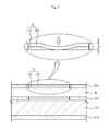
- the transparent window 35 is formed with the OCA 312 and the hard coating film 359 stacked one over the other at thickness d to allow itself to be coplanar with the surface of the flip cover 220 as shown in FIG. 7 .
- the hard coating film 359 may be slightly bent or deformed around the touched portion and so damaged because of the nature of the OCA 312 relatively soft.
- a reinforcing film 313 may be formed between the hard coating film 359 of the transparent window 35 and the cover plate 30 as shown in FIG. 8 , according to an embodiment of the present invention.
- the reinforcing film 313 is preferably formed of a transparent material, such as PET or PC.
- the transparent window 35 may be formed by sequentially stacking and attaching the reinforcing film 313 and the protective film 358 separately on a surface of the cover plate 30 .
- the separate reinforcing film 313 may be attached onto a surface of the cover plate 30 using a transparent adhesive, the OCA 312 , and then, the hard coating film 359 may be attached onto a surface of the reinforcing film 313 using the OCA 312 .
- a plurality of reinforcing films 313 may be stacked and attached using the OCA 312 .
- the transparent window 35 is at thickness d, as described above in connection with FIG. 4 , even when forming the transparent window 35 by sequentially stacking and attaching the reinforcing film 313 and the hard coating film 359 on a surface of the cover plate 30 .
- the user touches the transparent window 35 for manipulation or pressurizes the outer surface of the hard coating film 359
- the OCA layer 312 is relatively thin, the degree of deformation of the hard coating film 359 around the pressurized portion is relatively reduced as compared with the case illustrated in FIG. 8 .
- the hard coating film 359 is backed up in strength by the reinforcing film 313 , and the degree of deformation of the hard coating film 359 is relatively reduced. Accordingly, the transparent window 35 of such structure may prevent damage to the hard coating film 359 , leading to further increased durability.
- At least one of the cover plate 30 , the hard coating film 359 , and the reinforcing film 313 may be mixed with paint with a color, allowing the transparent window 35 a predetermined color to meet the user's preference.
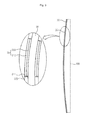
- the front surface 110 of the mobile terminal 100 may come in curved shape.
- the flip cover 220 of the dust filter 200 should be formed curved as well.
- the cover plate 30 and the transparent window 35 placed in the flip cover 220 are also formed to have a curved surface as shown in FIG. 9 .
- the transparent touch part with the same curved surface as the inner film is difficult to cutting-process, and thus, the defect rate is increased.
- the cover plate 30 may be easily formed through an injection molding process to have a curved surface, and the transparent window 35 may be formed by simply attaching the hard coating film 359 onto the curved cover plate 30 . Accordingly, a curved cover plate 30 and transparent window 35 may be easily manufactured.
Landscapes
- Engineering & Computer Science (AREA)
- Signal Processing (AREA)
- Computer Networks & Wireless Communication (AREA)
- Telephone Set Structure (AREA)
- Casings For Electric Apparatus (AREA)
Abstract
Description
Claims (14)
Applications Claiming Priority (5)
| Application Number | Priority Date | Filing Date | Title |
|---|---|---|---|
| KR10-2013-0091996 | 2013-08-02 | ||
| KR1020130091996A KR20130094274A (en) | 2013-08-02 | 2013-08-02 | Flip cove plate for mobile device |
| KR10-2013-0107409 | 2013-09-06 | ||
| KR1020130107409A KR101344240B1 (en) | 2013-08-02 | 2013-09-06 | Flip cove plate for mobile device |
| PCT/KR2013/011463 WO2015016435A1 (en) | 2013-08-02 | 2013-12-11 | Flip cover plate for mobile terminal |
Publications (2)
| Publication Number | Publication Date |
|---|---|
| US20160142090A1 US20160142090A1 (en) | 2016-05-19 |
| US9391663B2 true US9391663B2 (en) | 2016-07-12 |
Family
ID=49218139
Family Applications (1)
| Application Number | Title | Priority Date | Filing Date |
|---|---|---|---|
| US14/433,034 Active US9391663B2 (en) | 2013-08-02 | 2013-12-11 | Flip cover plate for mobile terminal |
Country Status (5)
| Country | Link |
|---|---|
| US (1) | US9391663B2 (en) |
| KR (2) | KR20130094274A (en) |
| CN (1) | CN104703502B (en) |
| IN (1) | IN2015DN02922A (en) |
| WO (1) | WO2015016435A1 (en) |
Cited By (2)
| Publication number | Priority date | Publication date | Assignee | Title |
|---|---|---|---|---|
| US20170079392A1 (en) * | 2015-09-23 | 2017-03-23 | Chia-Hao Lin | Protective Case for Portable Electronic Device |
| US10651882B2 (en) | 2016-07-20 | 2020-05-12 | Samsung Electronics Co., Ltd. | Case for electronic device |
Families Citing this family (11)
| Publication number | Priority date | Publication date | Assignee | Title |
|---|---|---|---|---|
| KR102211092B1 (en) | 2014-03-13 | 2021-02-02 | 삼성전자주식회사 | Case, electronic apparatus, and controlling method of electronic apparatus |
| KR102269779B1 (en) * | 2014-03-28 | 2021-06-28 | 삼성전자주식회사 | Method for displaying screen in electronic device and the electronic device |
| KR102339856B1 (en) * | 2014-12-24 | 2021-12-16 | 삼성전자주식회사 | Electronic decvice |
| KR101673430B1 (en) * | 2015-02-03 | 2016-11-08 | 윤남운 | Flip cover case for mobile device |
| USD795826S1 (en) * | 2015-02-05 | 2017-08-29 | Lg Electronics Inc. | Mobile phone |
| KR102381445B1 (en) * | 2015-02-16 | 2022-04-01 | 삼성전자주식회사 | Method for recognizing flip cover of electronic device, electronic device, and flip cover |
| US9473192B2 (en) * | 2015-03-10 | 2016-10-18 | Incipio, Llc | Protective case for mobile device having cover with opaque and transparent regions |
| WO2018016729A1 (en) * | 2016-07-20 | 2018-01-25 | 삼성전자 주식회사 | Case for electronic device |
| KR102613168B1 (en) * | 2017-01-04 | 2023-12-14 | 삼성전자 주식회사 | Cover accessory and electronic device using the same |
| CN107415372A (en) * | 2017-06-07 | 2017-12-01 | 东莞市裕鼎纳米科技有限公司 | A kind of covering plate structure and its processing method that may replace 3D heat-bending glass |
| US12019472B2 (en) * | 2022-07-31 | 2024-06-25 | Lenovo (Singapore) Pte. Ltd | Computing device |
Citations (8)
| Publication number | Priority date | Publication date | Assignee | Title |
|---|---|---|---|---|
| CN2488234Y (en) * | 2001-05-11 | 2002-04-24 | 刘瑞琳 | Cases for mobile phones |
| JP2007329697A (en) * | 2006-06-08 | 2007-12-20 | Sharp Corp | Foldable portable electronic device |
| KR100942340B1 (en) | 2009-03-26 | 2010-02-12 | 최효영 | Protection cover for personal digitalassistant |
| KR20100010008U (en) | 2009-04-02 | 2010-10-12 | (주)중앙티앤씨 | a protection case for mobile phone |
| KR20120005719U (en) | 2012-06-25 | 2012-08-08 | 임동춘 | Case for mobile phone |
| KR101192287B1 (en) | 2012-05-24 | 2012-10-17 | 서경진 | Wallet type handphone case with see through window |
| KR200467637Y1 (en) | 2012-11-09 | 2013-07-02 | 주식회사 포미 | The case for cellular phone with the mirror |
| KR20130093046A (en) | 2013-05-07 | 2013-08-21 | 윤남운 | Mobile phone protection case with trnsparent part and its making method |
Family Cites Families (4)
| Publication number | Priority date | Publication date | Assignee | Title |
|---|---|---|---|---|
| TWM359227U (en) * | 2008-09-05 | 2009-06-21 | Xin-Yuan Yu | Improvement of protection sheath of mobile phone |
| CN102006739A (en) * | 2009-09-03 | 2011-04-06 | 鸿富锦精密工业(深圳)有限公司 | Shell |
| KR20110007366U (en) * | 2010-01-18 | 2011-07-26 | 윤 호 김 | A case for mobile communication terminal |
| CN201847001U (en) * | 2010-09-08 | 2011-06-01 | 东莞洲进电子塑胶五金有限公司 | Replaceable Handheld Electronics Case |
-
2013
- 2013-08-02 KR KR1020130091996A patent/KR20130094274A/en active Pending
- 2013-09-06 KR KR1020130107409A patent/KR101344240B1/en active Active
- 2013-12-11 CN CN201380053092.3A patent/CN104703502B/en active Active
- 2013-12-11 IN IN2922DEN2015 patent/IN2015DN02922A/en unknown
- 2013-12-11 US US14/433,034 patent/US9391663B2/en active Active
- 2013-12-11 WO PCT/KR2013/011463 patent/WO2015016435A1/en not_active Ceased
Patent Citations (8)
| Publication number | Priority date | Publication date | Assignee | Title |
|---|---|---|---|---|
| CN2488234Y (en) * | 2001-05-11 | 2002-04-24 | 刘瑞琳 | Cases for mobile phones |
| JP2007329697A (en) * | 2006-06-08 | 2007-12-20 | Sharp Corp | Foldable portable electronic device |
| KR100942340B1 (en) | 2009-03-26 | 2010-02-12 | 최효영 | Protection cover for personal digitalassistant |
| KR20100010008U (en) | 2009-04-02 | 2010-10-12 | (주)중앙티앤씨 | a protection case for mobile phone |
| KR101192287B1 (en) | 2012-05-24 | 2012-10-17 | 서경진 | Wallet type handphone case with see through window |
| KR20120005719U (en) | 2012-06-25 | 2012-08-08 | 임동춘 | Case for mobile phone |
| KR200467637Y1 (en) | 2012-11-09 | 2013-07-02 | 주식회사 포미 | The case for cellular phone with the mirror |
| KR20130093046A (en) | 2013-05-07 | 2013-08-21 | 윤남운 | Mobile phone protection case with trnsparent part and its making method |
Non-Patent Citations (6)
| Title |
|---|
| English Specification of 10-0942340. |
| English Specification of 10-1192287. |
| English Specification of 10-2013-0093046. |
| English Specification of 20-0467637. |
| English Specification of 20-2010-0010008. |
| English Specification of 20-2012-0005719. |
Cited By (2)
| Publication number | Priority date | Publication date | Assignee | Title |
|---|---|---|---|---|
| US20170079392A1 (en) * | 2015-09-23 | 2017-03-23 | Chia-Hao Lin | Protective Case for Portable Electronic Device |
| US10651882B2 (en) | 2016-07-20 | 2020-05-12 | Samsung Electronics Co., Ltd. | Case for electronic device |
Also Published As
| Publication number | Publication date |
|---|---|
| WO2015016435A1 (en) | 2015-02-05 |
| KR101344240B1 (en) | 2013-12-23 |
| CN104703502B (en) | 2017-07-21 |
| CN104703502A (en) | 2015-06-10 |
| KR20130094274A (en) | 2013-08-23 |
| IN2015DN02922A (en) | 2015-09-18 |
| US20160142090A1 (en) | 2016-05-19 |
Similar Documents
| Publication | Publication Date | Title |
|---|---|---|
| US9391663B2 (en) | Flip cover plate for mobile terminal | |
| CN102823338B (en) | Glass composite, electronic device using glass composite, and input device | |
| US12496817B2 (en) | Cover window and apparatus and method for manufacturing the cover window | |
| US9974199B2 (en) | Electronic device having a display and method for manufacture | |
| JP2014026282A (en) | Combined light guide plate and display device | |
| US20160046049A1 (en) | Mobile phone protection case film with transparent part and method for manufacturing same | |
| CN104866019A (en) | Display components and terminals | |
| CN104536518A (en) | Terminal front cover, terminal front cover assembly and terminal | |
| US8532480B2 (en) | Electronic device, cover and method | |
| KR20150019204A (en) | Front window cover for touch screen display device and method for producing the same | |
| US11529789B2 (en) | Mobile terminal | |
| CN104865721A (en) | Display assembly method | |
| KR20170090383A (en) | Manufacturing method of protected cover for display panel with bented edge | |
| CN204406268U (en) | Terminal protecgulum, terminal front cover component and terminal | |
| US20150237756A1 (en) | Method and apparatus for seamlessly affixing a protective film to an electronic device | |
| KR20160124989A (en) | Manufacturing method of protected cover for display panel with bented edge and Protected cover for display panel with bented edge | |
| CN111355832A (en) | Unequal thickness shell, its processing method and terminal equipment | |
| CN202085203U (en) | Mobile phone component with integrally injection-molded glass | |
| KR101673430B1 (en) | Flip cover case for mobile device | |
| KR102929992B1 (en) | Window cover for display device and manufacturing method thereof | |
| CN219420814U (en) | Covers and Electronics | |
| KR101351436B1 (en) | Method for manufacturing a view cover for a lcd screen of an electronic device and a view cover manufactured thereby | |
| TWI723306B (en) | Electronic device casing and manufacturing method thereof | |
| TW202534390A (en) | Display apparatus | |
| WO2013129238A1 (en) | Laminated component and method for manufacturing same |
Legal Events
| Date | Code | Title | Description |
|---|---|---|---|
| STCF | Information on status: patent grant |
Free format text: PATENTED CASE |
|
| AS | Assignment |
Owner name: VONICK INTERNATIONAL INC., WASHINGTON Free format text: ASSIGNMENT OF ASSIGNORS INTEREST;ASSIGNORS:YUN, NAM WOON;YUN, MIN SEOK;LEE, NAM HEE;REEL/FRAME:044506/0580 Effective date: 20171219 |
|
| AS | Assignment |
Owner name: YUN, NAM WOON, KOREA, REPUBLIC OF Free format text: ASSIGNMENT OF ASSIGNORS INTEREST;ASSIGNOR:VONICK INTERNATIONAL INC.;REEL/FRAME:050963/0185 Effective date: 20191105 Owner name: LEE, NAM HEE, KOREA, REPUBLIC OF Free format text: ASSIGNMENT OF ASSIGNORS INTEREST;ASSIGNOR:VONICK INTERNATIONAL INC.;REEL/FRAME:050963/0185 Effective date: 20191105 Owner name: YUN, MIN SEOK, KOREA, REPUBLIC OF Free format text: ASSIGNMENT OF ASSIGNORS INTEREST;ASSIGNOR:VONICK INTERNATIONAL INC.;REEL/FRAME:050963/0185 Effective date: 20191105 |
|
| FEPP | Fee payment procedure |
Free format text: MAINTENANCE FEE REMINDER MAILED (ORIGINAL EVENT CODE: REM.); ENTITY STATUS OF PATENT OWNER: SMALL ENTITY |
|
| FEPP | Fee payment procedure |
Free format text: SURCHARGE FOR LATE PAYMENT, SMALL ENTITY (ORIGINAL EVENT CODE: M2554); ENTITY STATUS OF PATENT OWNER: SMALL ENTITY |
|
| MAFP | Maintenance fee payment |
Free format text: PAYMENT OF MAINTENANCE FEE, 4TH YR, SMALL ENTITY (ORIGINAL EVENT CODE: M2551); ENTITY STATUS OF PATENT OWNER: SMALL ENTITY Year of fee payment: 4 |
|
| FEPP | Fee payment procedure |
Free format text: MAINTENANCE FEE REMINDER MAILED (ORIGINAL EVENT CODE: REM.); ENTITY STATUS OF PATENT OWNER: SMALL ENTITY |