US9358627B2 - Method for machining a workpiece - Google Patents
Method for machining a workpiece Download PDFInfo
- Publication number
- US9358627B2 US9358627B2 US13/800,710 US201313800710A US9358627B2 US 9358627 B2 US9358627 B2 US 9358627B2 US 201313800710 A US201313800710 A US 201313800710A US 9358627 B2 US9358627 B2 US 9358627B2
- Authority
- US
- United States
- Prior art keywords
- workpiece
- peeling tool
- hob peeling
- axis
- hob
- Prior art date
- Legal status (The legal status is an assumption and is not a legal conclusion. Google has not performed a legal analysis and makes no representation as to the accuracy of the status listed.)
- Expired - Fee Related, expires
Links
Images


Classifications
-
- B—PERFORMING OPERATIONS; TRANSPORTING
- B23—MACHINE TOOLS; METAL-WORKING NOT OTHERWISE PROVIDED FOR
- B23F—MAKING GEARS OR TOOTHED RACKS
- B23F15/00—Methods or machines for making gear wheels of special kinds not covered by groups B23F7/00 - B23F13/00
- B23F15/06—Making gear teeth on the front surface of wheels, e.g. for clutches or couplings with toothed faces
-
- B—PERFORMING OPERATIONS; TRANSPORTING
- B23—MACHINE TOOLS; METAL-WORKING NOT OTHERWISE PROVIDED FOR
- B23F—MAKING GEARS OR TOOTHED RACKS
- B23F5/00—Making straight gear teeth involving moving a tool relatively to a workpiece with a rolling-off or an enveloping motion with respect to the gear teeth to be made
- B23F5/12—Making straight gear teeth involving moving a tool relatively to a workpiece with a rolling-off or an enveloping motion with respect to the gear teeth to be made by planing or slotting
- B23F5/16—Making straight gear teeth involving moving a tool relatively to a workpiece with a rolling-off or an enveloping motion with respect to the gear teeth to be made by planing or slotting the tool having a shape similar to that of a spur wheel or part thereof
- B23F5/163—Making straight gear teeth involving moving a tool relatively to a workpiece with a rolling-off or an enveloping motion with respect to the gear teeth to be made by planing or slotting the tool having a shape similar to that of a spur wheel or part thereof the tool and workpiece being in crossed axis arrangement, e.g. skiving, i.e. "Waelzschaelen"
-
- Y—GENERAL TAGGING OF NEW TECHNOLOGICAL DEVELOPMENTS; GENERAL TAGGING OF CROSS-SECTIONAL TECHNOLOGIES SPANNING OVER SEVERAL SECTIONS OF THE IPC; TECHNICAL SUBJECTS COVERED BY FORMER USPC CROSS-REFERENCE ART COLLECTIONS [XRACs] AND DIGESTS
- Y10—TECHNICAL SUBJECTS COVERED BY FORMER USPC
- Y10T—TECHNICAL SUBJECTS COVERED BY FORMER US CLASSIFICATION
- Y10T409/00—Gear cutting, milling, or planing
- Y10T409/10—Gear cutting
- Y10T409/101431—Gear tooth shape generating
- Y10T409/10159—Hobbing
- Y10T409/101749—Process
Definitions
- the present invention relates to a method for machining a workpiece.
- method for machining a workpiece includes rotating a workpiece about a Z axis of a coordinate system with X, Y and Z axes arranged perpendicularly to one another, arranging a hob peeling tool in an X-Z plane at an angle to the X axis which is greater than 0° and less than 20°, and feeding the hob peeling tool in a direction of the workpiece to provide an end face of the workpiece with an end face gearing by hob peeling, with the feeding direction of the hob peeling tool enclosing with an axis of rotation of the hob peeling tool an angle which is greater than 0° and less than 35°.
- Hob peeling is in principle known as a manufacturing process for manufacturing gearings on workpieces. It is one of the group of continuous gear wheel manufacturing processes with geometrically defined cutting edges.
- the axis of rotation of the hob peeling tool is inclined to the tool feed direction at an angle which is not equal to 0.
- the resulting relative movement between the workpiece and the tool corresponds to a screw movement which can be split into a rotational part and a thrust part, wherein the thrust part is used to implement the cutting movement.
- Hob peeling is however at present used exclusively to provide rotationally symmetrical workpieces with external or internal gearing along their circular external or internal circumference.
- hob peeling can alternatively also be used to create end face gearing on the end face of a workpiece, wherein the end face is preferably embodied as annular and flat.
- the use of hob peeling is associated in particular with the advantage of very short machining times. It can be performed on a conventional turning/milling center, so that many different types of machining can be implemented in a single workpiece clamping operation. As a result short throughput times, very good rotational properties of the workpiece and high machine utilization can be achieved. Moreover it is not necessary to purchase a separate gearing machine, resulting in low investment costs.
- the angle between the feeding direction and the axis of rotation can range between 15° and 25°.
- the hob peeling tool can have a plurality of longitudinal cutting edges arranged about a circumference of the hob peeling tool.
- the cutting edges of the hob peeling tool are advantageously spaced apart from one another in the circumferential direction, wherein the respective distances in the circumferential direction each correspond to a whole-number multiple of a cutting edge width.
- At least one further machining of the workpiece may be carried out on the same machine tool while retaining the workpiece clamping, in particular turning and/or milling and/or drilling, in addition to the creation of the end face gearing.
- the performance of multiple machining steps on the same machine tool while retaining the workpiece clamping is associated with short machining times, short throughput times and high rotational accuracy.
- the method can be performed on a turning/milling center. Accordingly it is not necessary to purchase a separate gearing machine, and hence the investment costs can be kept low.
- FIG. 1 shows a schematic front view of components of a turning/milling center for manufacturing an end face gearing on an end face of a workpiece in accordance with the present invention
- FIG. 2 shows a schematic view of the turning/milling center in a direction of arrow II in FIG. 1 ;
- FIG. 3 shows a side view of an embodiment of a hob peeling tool which can be used in the execution of the method according to the present invention
- FIG. 4 shows a bottom view of the hob peeling tool of FIG. 3 ;
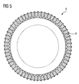
- FIG. 5 shows a top view of a workpiece which is provided on its end face with an end face gearing manufactured with the hob peeling tool shown in FIGS. 3 and 4 ;
- FIG. 6 shows a perspective partial side view of the workpiece shown in FIG. 5 ;
- FIG. 7 shows a perspective partial side view of two workpieces illustrated in FIGS. 5 and 6 , which are aligned axially to another and having end face gearings meshing with one another in the manner of a coupling.
- the turning/milling center 1 has a main spindle 2 and a milling spindle 3 .
- the main spindle 2 is provided with a chuck for accommodating a workpiece 4
- the milling spindle 3 is provided with a chuck for accommodating a hob peeling tool 5 .
- the chuck of the milling spindle 3 can of course also accommodate a milling or drilling tool.
- the turning/milling center 1 further includes, in known fashion, a slide (not shown in greater detail) with a tool revolver for accommodating different turning tools, so that turning operations can be performed on the turning/milling center 1 .
- the main spindle 2 and the milling spindle 3 can be controlled such that they can be rotated synchronously with one another.
- the milling spindle 3 can move steplessly in the X, Y and Z direction.
- the hob peeling tool 5 is shown in greater detail in FIGS. 3 and 4 .
- the hob peeling tool 5 is provided with a plurality of circumferentially arranged, longitudinally embodied and radially projecting cutting edges 6 .
- the cutting edges 6 of the hob peeling tool 5 are spaced apart from one another in the circumferential direction, wherein the respective distances a in the circumferential direction correspond to a whole-number multiple of a cutting edge width B.
- a cutting edge 6 is in each case omitted between two adjacent cutting edges 6 .
- the milling spindle 3 and thus the axis of rotation 10 of the hob peeling tool 5 are arranged as a function of the desired tooth bearing of the gearing to be created in the X-Z plane at an angle ⁇ to the X axis, as shown in FIG. 2 , wherein ⁇ is normally greater than 0° and less than 20°.
- the milling spindle 3 is positioned such that the axis of rotation 10 of the hob peeling tool 5 is positioned in the Y direction offset by a distance A to the X axis.
- the hob peeling tool 5 is arranged off-center in respect of the workpiece 4 in the Y direction.
- the hob peeling tool 5 is moved relative to the workpiece 4 with a radial feed S r both in the X and in the Y direction, while the workpiece 4 and the hob peeling tool 5 are rotated synchronously about their respective axes of rotation 9 and 10 .
- the feed direction of the hob peeling tool 5 thus encloses an angle ⁇ with the axis of rotation 10 of the hob peeling tool 5 , wherein ⁇ is greater than 0° and less than 35° and in particular lies in the range between 15° and 25°.
- the angle ⁇ determines the cutting speed with which the workpiece 4 is machined.
- an axial feed S ax can be executed in the Z direction as an infeed movement.
- the end face gearing 7 is created on the end face 6 of the workpiece 4 corresponding to the shape of the hob peeling tool 5 , as shown in FIGS. 5 and 6 , wherein the tops of the tooth crests of the finished end face gearing 7 lie in a common plane.
- FIG. 7 shows two identically embodied workpieces 4 , which have each been inventively provided with an end face gearing 8 using the hob peeling process.
- the workpieces 4 are axially aligned to one another and arranged such that their end face gearings 8 mesh with one another in the manner of a coupling.
Landscapes
- Engineering & Computer Science (AREA)
- Mechanical Engineering (AREA)
- Gear Processing (AREA)
- Milling Processes (AREA)
Abstract
Description
Claims (9)
Applications Claiming Priority (2)
| Application Number | Priority Date | Filing Date | Title |
|---|---|---|---|
| EP12159484.0A EP2639001B1 (en) | 2012-03-14 | 2012-03-14 | Method for machining a workpiece |
| EP12159484 | 2012-03-14 |
Publications (2)
| Publication Number | Publication Date |
|---|---|
| US20130243540A1 US20130243540A1 (en) | 2013-09-19 |
| US9358627B2 true US9358627B2 (en) | 2016-06-07 |
Family
ID=45887959
Family Applications (1)
| Application Number | Title | Priority Date | Filing Date |
|---|---|---|---|
| US13/800,710 Expired - Fee Related US9358627B2 (en) | 2012-03-14 | 2013-03-13 | Method for machining a workpiece |
Country Status (4)
| Country | Link |
|---|---|
| US (1) | US9358627B2 (en) |
| EP (1) | EP2639001B1 (en) |
| CN (1) | CN103302360B (en) |
| ES (1) | ES2641223T3 (en) |
Families Citing this family (16)
| Publication number | Priority date | Publication date | Assignee | Title |
|---|---|---|---|---|
| JP6340764B2 (en) | 2013-08-08 | 2018-06-13 | 株式会社ジェイテクト | Gear processing equipment |
| DE102013015252A1 (en) | 2013-09-13 | 2015-03-19 | Gleason-Pfauter Maschinenfabrik Gmbh | Coolant supply and thus equipped Wälzschälmaschine and thus executed Wälzschälverfahren |
| JP6620393B2 (en) * | 2014-05-19 | 2019-12-18 | 株式会社ジェイテクト | Gear machining method |
| DE102014218082B4 (en) * | 2014-09-10 | 2016-11-10 | Felsomat Gmbh & Co. Kg | Device for hobbing machining of a workpiece for producing a chamfer and associated operating method |
| JP6471504B2 (en) * | 2015-01-09 | 2019-02-20 | アイシン精機株式会社 | Crown gear manufacturing equipment |
| LU93121B1 (en) | 2016-06-27 | 2018-01-09 | Ovalo Gmbh | Gear, method for producing the teeth, as well as tools for producing the teeth of a gear |
| LU93122B1 (en) * | 2016-06-27 | 2018-01-09 | Ovalo Gmbh | Gear, method for producing the toothing of a gear, and tool gear for producing the teeth of a gear |
| LU93123B1 (en) | 2016-06-27 | 2018-01-09 | Ovalo Gmbh | Voltage shaft gear, gear for a voltage wave gear, and method for producing the teeth of a gear for a stress wave transmission |
| DE102016008435A1 (en) * | 2016-07-11 | 2018-01-11 | Gleason-Pfauter Maschinenfabrik Gmbh | Radial gear tool |
| DE102017125602A1 (en) * | 2016-11-04 | 2018-05-09 | Jtekt Corporation | Gear processing device and gear processing method |
| DE102017006553A1 (en) * | 2017-07-11 | 2019-01-17 | Gleason-Pfauter Maschinenfabrik Gmbh | Method for machining a toothing and toothing machine prepared therefor |
| DE102018112865B3 (en) | 2018-05-29 | 2019-10-17 | Hartmetall-Werkzeugfabrik Paul Horn Gmbh | Wälzschälwerkzeug |
| US10780512B2 (en) * | 2018-08-24 | 2020-09-22 | Gleason Cutting Tools Corporation | Multi-component gear cutting tool |
| CN110280818B (en) * | 2019-07-01 | 2021-02-02 | 苏州真懿精密器械有限公司 | Method for improving surface roughness of micro part in milling process |
| EP4045218B1 (en) * | 2019-10-17 | 2025-07-23 | Eaton Intelligent Power Limited | Coolant delivery assembly and method of forming a gear using a gear cutter tool and a retaining cooling nut |
| DE102021102098A1 (en) * | 2021-01-29 | 2022-08-04 | Präwema Antriebstechnik GmbH | Tool and method for producing deposits on the teeth of a gear tooth system |
Citations (10)
| Publication number | Priority date | Publication date | Assignee | Title |
|---|---|---|---|---|
| US2308891A (en) | 1939-04-05 | 1943-01-19 | Fellows Gear Shaper Co | Method and apparatus for gear generation |
| US2598327A (en) * | 1946-06-19 | 1952-05-27 | Gleason Works | Method and machine for cutting gears |
| US3089392A (en) * | 1957-07-10 | 1963-05-14 | Romi Giordano | Method and mechanism for generating gears, racks and the like |
| US3399599A (en) * | 1965-10-01 | 1968-09-03 | Zahnradfabrik Friedrichshafen | Gear hobbing machine |
| DE10305752A1 (en) | 2003-02-11 | 2004-10-07 | Rheinisch-Westfälisch- Technische Hochschule Aachen | Production of periodic structures e.g. toothed wheels and toothed arrangements on cylindrical components comprises metal-cutting machining carried out by a succession of hob peeling and shaving without tool exchange in one machine |
| DE102007015357A1 (en) | 2007-03-30 | 2008-10-02 | Profilator Gmbh & Co. Kg | Toothing device for fabricating inner or outer toothed gear wheels, where revs of tool spindle matches a multiple of the workpiece spindle |
| US20080266750A1 (en) | 2007-04-25 | 2008-10-30 | Industrial Technology Research Institute | Capacitor Devices |
| DE102009003601A1 (en) | 2009-03-11 | 2010-09-16 | Profilator Gmbh & Co. Kg | Apparatus and method for manufacturing a bevel gear, in particular a crown wheel |
| US20120003058A1 (en) * | 2008-12-19 | 2012-01-05 | Wolfgang Hutter | Machine tool and method for producing gearing |
| US20120148360A1 (en) * | 2009-06-10 | 2012-06-14 | Profilator Gmbh & Co. Kg | Device and method for hob peeling internally geared wheels and related peeling wheel |
Family Cites Families (2)
| Publication number | Priority date | Publication date | Assignee | Title |
|---|---|---|---|---|
| CA2581724C (en) * | 2005-02-03 | 2010-11-30 | David J. Fisher | Method and apparatus for manufacturing a face gear |
| DE202011050054U1 (en) | 2011-05-06 | 2011-09-15 | Klingelnberg Ag | Skiving tool with knife bars |
-
2012
- 2012-03-14 EP EP12159484.0A patent/EP2639001B1/en active Active
- 2012-03-14 ES ES12159484.0T patent/ES2641223T3/en active Active
-
2013
- 2013-03-12 CN CN201310078723.9A patent/CN103302360B/en active Active
- 2013-03-13 US US13/800,710 patent/US9358627B2/en not_active Expired - Fee Related
Patent Citations (10)
| Publication number | Priority date | Publication date | Assignee | Title |
|---|---|---|---|---|
| US2308891A (en) | 1939-04-05 | 1943-01-19 | Fellows Gear Shaper Co | Method and apparatus for gear generation |
| US2598327A (en) * | 1946-06-19 | 1952-05-27 | Gleason Works | Method and machine for cutting gears |
| US3089392A (en) * | 1957-07-10 | 1963-05-14 | Romi Giordano | Method and mechanism for generating gears, racks and the like |
| US3399599A (en) * | 1965-10-01 | 1968-09-03 | Zahnradfabrik Friedrichshafen | Gear hobbing machine |
| DE10305752A1 (en) | 2003-02-11 | 2004-10-07 | Rheinisch-Westfälisch- Technische Hochschule Aachen | Production of periodic structures e.g. toothed wheels and toothed arrangements on cylindrical components comprises metal-cutting machining carried out by a succession of hob peeling and shaving without tool exchange in one machine |
| DE102007015357A1 (en) | 2007-03-30 | 2008-10-02 | Profilator Gmbh & Co. Kg | Toothing device for fabricating inner or outer toothed gear wheels, where revs of tool spindle matches a multiple of the workpiece spindle |
| US20080266750A1 (en) | 2007-04-25 | 2008-10-30 | Industrial Technology Research Institute | Capacitor Devices |
| US20120003058A1 (en) * | 2008-12-19 | 2012-01-05 | Wolfgang Hutter | Machine tool and method for producing gearing |
| DE102009003601A1 (en) | 2009-03-11 | 2010-09-16 | Profilator Gmbh & Co. Kg | Apparatus and method for manufacturing a bevel gear, in particular a crown wheel |
| US20120148360A1 (en) * | 2009-06-10 | 2012-06-14 | Profilator Gmbh & Co. Kg | Device and method for hob peeling internally geared wheels and related peeling wheel |
Non-Patent Citations (1)
| Title |
|---|
| Hünecke C: "Reliable and efficient skiving", Gear Technology, Randall Publishing Co. Elk Grove, Illinois, US, Sep. 1, 2011, pp. 11-13, XP007920036, ISSN: 0743-6858; 2011; Sep. 1, 2011. |
Also Published As
| Publication number | Publication date |
|---|---|
| ES2641223T3 (en) | 2017-11-08 |
| EP2639001B1 (en) | 2017-06-28 |
| CN103302360B (en) | 2015-10-28 |
| US20130243540A1 (en) | 2013-09-19 |
| CN103302360A (en) | 2013-09-18 |
| EP2639001A1 (en) | 2013-09-18 |
Similar Documents
| Publication | Publication Date | Title |
|---|---|---|
| US9358627B2 (en) | Method for machining a workpiece | |
| US11858054B2 (en) | Gearing method with tooth finishing and combination tool therefor | |
| EP2428295B1 (en) | Tool post | |
| US6079090A (en) | Numeric-control machine tool for turning and hobbing mechanical parts | |
| US10994352B2 (en) | Method for the gear manufacturing machining of a workpiece | |
| CN101733486B (en) | Machining method of cutting cylindrical gear | |
| US20130121779A1 (en) | Method and device for machining tooth edges | |
| KR20120139595A (en) | Method for gear pre-cutting of a plurality of different bevel gears and use of an according milling tool | |
| KR20120034728A (en) | Device and method for hob peeling internally geared wheels and related peeling wheel | |
| EP2516092B1 (en) | Method and apparatus for manufacturing bevel gears | |
| US20070209179A1 (en) | Lathe hobbing tool | |
| JP2020114616A (en) | Gear processing device and gear processing method | |
| US20130164090A1 (en) | Multi-Spindle Hobbing Machine | |
| CN204673092U (en) | High-accuracy high-efficiency herringbone bear machining tool | |
| JP6565399B2 (en) | Gear processing equipment | |
| US6336777B1 (en) | Face hobbing of hypoid gears using a two-spindle machine | |
| KR20200000189A (en) | apparatus of the shaft type roller gear cam | |
| JP2019089153A (en) | Gear-cutting tool and gear processing device | |
| CN101780640A (en) | Method for processing machine elements and device thereof | |
| CN207629799U (en) | The special grinding machine of multiaxis main shaft mandrel | |
| CN114260738A (en) | High-precision thin-wall type half-coupling turning tool and method | |
| CN112338292A (en) | Narrow clearance groove herringbone tooth cutting machining method | |
| CN104874867A (en) | High-precision and high-efficiency herringbone gear machine tool | |
| RU2787187C1 (en) | Breaking head with cutting inserts for machining the teeth of worm and spiroid wheels | |
| CN113275668A (en) | Bidirectional hob, chamfering, groove milling and deburring method |
Legal Events
| Date | Code | Title | Description |
|---|---|---|---|
| AS | Assignment |
Owner name: SIEMENS AKTIENGESELLSCHAFT, GERMANY Free format text: ASSIGNMENT OF ASSIGNORS INTEREST;ASSIGNOR:SCHAFFELD, RICHARD;REEL/FRAME:030141/0654 Effective date: 20130326 |
|
| FEPP | Fee payment procedure |
Free format text: PAYOR NUMBER ASSIGNED (ORIGINAL EVENT CODE: ASPN); ENTITY STATUS OF PATENT OWNER: LARGE ENTITY |
|
| ZAAA | Notice of allowance and fees due |
Free format text: ORIGINAL CODE: NOA |
|
| ZAAB | Notice of allowance mailed |
Free format text: ORIGINAL CODE: MN/=. |
|
| STCF | Information on status: patent grant |
Free format text: PATENTED CASE |
|
| AS | Assignment |
Owner name: FLENDER GMBH, GERMANY Free format text: ASSIGNMENT OF ASSIGNORS INTEREST;ASSIGNOR:SIEMENS AKTIENGESELLSCHAFT;REEL/FRAME:044333/0019 Effective date: 20171012 |
|
| MAFP | Maintenance fee payment |
Free format text: PAYMENT OF MAINTENANCE FEE, 4TH YEAR, LARGE ENTITY (ORIGINAL EVENT CODE: M1551); ENTITY STATUS OF PATENT OWNER: LARGE ENTITY Year of fee payment: 4 |
|
| FEPP | Fee payment procedure |
Free format text: MAINTENANCE FEE REMINDER MAILED (ORIGINAL EVENT CODE: REM.); ENTITY STATUS OF PATENT OWNER: LARGE ENTITY |
|
| LAPS | Lapse for failure to pay maintenance fees |
Free format text: PATENT EXPIRED FOR FAILURE TO PAY MAINTENANCE FEES (ORIGINAL EVENT CODE: EXP.); ENTITY STATUS OF PATENT OWNER: LARGE ENTITY |
|
| STCH | Information on status: patent discontinuation |
Free format text: PATENT EXPIRED DUE TO NONPAYMENT OF MAINTENANCE FEES UNDER 37 CFR 1.362 |
|
| FP | Lapsed due to failure to pay maintenance fee |
Effective date: 20240607 |