US935726A - Sewing-machine. - Google Patents
Sewing-machine. Download PDFInfo
- Publication number
- US935726A US935726A US14129003A US1903141290A US935726A US 935726 A US935726 A US 935726A US 14129003 A US14129003 A US 14129003A US 1903141290 A US1903141290 A US 1903141290A US 935726 A US935726 A US 935726A
- Authority
- US
- United States
- Prior art keywords
- needle
- thread
- stitch
- sewing machine
- combination
- Prior art date
- Legal status (The legal status is an assumption and is not a legal conclusion. Google has not performed a legal analysis and makes no representation as to the accuracy of the status listed.)
- Expired - Lifetime
Links
- 238000009958 sewing Methods 0.000 description 29
- 239000000126 substance Substances 0.000 description 9
- 230000036461 convulsion Effects 0.000 description 6
- 238000009877 rendering Methods 0.000 description 3
- 229940000425 combination drug Drugs 0.000 description 2
- 235000003930 Aegle marmelos Nutrition 0.000 description 1
- 244000058084 Aegle marmelos Species 0.000 description 1
- 238000005773 Enders reaction Methods 0.000 description 1
- 230000000994 depressogenic effect Effects 0.000 description 1
- MXCPYJZDGPQDRA-UHFFFAOYSA-N dialuminum;2-acetyloxybenzoic acid;oxygen(2-) Chemical compound [O-2].[O-2].[O-2].[Al+3].[Al+3].CC(=O)OC1=CC=CC=C1C(O)=O MXCPYJZDGPQDRA-UHFFFAOYSA-N 0.000 description 1
- 230000000266 injurious effect Effects 0.000 description 1
- 150000002500 ions Chemical class 0.000 description 1
- 229920000136 polysorbate Polymers 0.000 description 1
Images

Classifications
-
- D—TEXTILES; PAPER
- D05—SEWING; EMBROIDERING; TUFTING
- D05B—SEWING
- D05B15/00—Machines for sewing leather goods
Definitions
- the present invention relates to sewing machines and more particularly to sewing V greatest importance to reduce to a machines of the curved hooked needle chain stitch type such as are commonly used for sewing turned shoes and for inseamin'g welted shoes.
- a machines of the curved hooked needle chain stitch type such as are commonly used for sewing turned shoes and for inseamin'g welted shoes.
- this class of machines it is of the minimum all outward strains on' the thread, that is to say,'all strains which tend to draw the thread outward from the median line of the shoe, also to reduce to a minimum the rendering of the thread under tension through the hook of the needle.
- the needle in pulling-out the'loop, is made to encounter the full teiisioiiresistance together with such further resistance as the thread itself olfers to slipping in the liookof the needle, which resistance is by no, ineans inconsi'd'erz'ible as the waxed I thread in the loop hasbe'eu previously drawn through the between substance andalinost to the limitof the stroke of the needle withoutany rendering. Itwill be seen from the Y I fofegoingby those skilled.
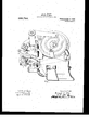
- Figure 1 o is a side elevation of a Goodyearwelt and turn machine embodying'the present invention, certain partsbeing omitted for clear- .ness, such parts being, among others, the welt guide, channel guide, channel guide lever, awl, awl lever, feed slide, needle cam and feed cam;
- Fig. '2 is a side elevation of the needle.
- Fig. 3 is a plan of the same;
- Fig; t is an elevation of the forward end of the needle lever showing a section of the sliding block carried thereby; and
- Fig. 5 is an elevation of the forward end of the needle lever showing a section of the sliding block carried thereby;
- . is a vertical transverse section of the forward end of. the needle lever showing the parts carried thereby.
- needle segment S and needle link 91 are also constructed substantially as described in said patent.
- the needle lever 1 is constructed and arranged as describedin said patent, except that at its forward end it is provided with a vertical slot 2- inwhichthe block 3 is slidingly fitted.
- the block 3 is normally o sup orted by the helical com ression spring 4 w ich at its upper end em races the rojection 5 on the under side of the bloc '3, and at its lower end embraces a similar projection from the spring cap 6.- The 5.
- spring cap 6 is adj ustab e-vertica ly, to vary the force exerted by the spring on the slidin block, by means of the adjusting screw which is screw threaded through the lower side of the lever 1 and engages a recess in the under side of the spring cap 6.
- a lock nut 8 is provided by meansof which the adjusting screw 7 ma be locked in an adjusted position.
- the sli' ing block 3 is rforated and receives the bolt 9 whic extends through the'adjacent end of the needle link 11. shown in dotted lines in Fig. 2.
- the operation of the illustrated embodiment of my invention is substantially the same as the o ration of the Goodyear .welt and turn mac inc as disclosed in said to French and Meyer, except that while the needle is making its retractin stroke it is controlled by the spring 5 so t at the stitch tightening ull upon t 0 thread instead of being rigid y applied thereto is yieldingly atent applied, thereby relieving the thread and between substance of the sudden twitch or jerk which occurs in said Goodyear machine.”
- YVhen-th'e needle lever 1 is depressed to advance the needle the slidi brought in contact with the upper end of the slot, 2, forcing the needle positively forward,
- a chain hook needle, and actuating mechanism for block 3 will be.
- the needle having, in combination, a looper, a curved I the needle having provision for yieldingly controlling said needle during its loop-drawing stroke, substantially as described.
- a chain stitch shoe sewing machine having, in combination, a'looper, a curved hook needle, and means for actuating the needle having provision for positively controlling the same during its work piercing stroke and yieldingly controlling t e same during its loop -drawingstroke, substan-' tially as described.
- a chain stitch shoe'sewing machine having, in combination, a looper, a curv hook needle, a needle lever, connections betilivefian the needle lever'and the'needle in c u stantia ly as described.
- A' chain stitch shoe sewing machin' having, in combination, alooper, acurv hook nee aneedle yided with a. 's'lot'in'its'end, a sliding b oc k arranged in said slot, a pin connecting said sliding block and the needle link, and a 5 ring normally acting upon the sliding block to hold itat oneend in the slot in the (1%e, a. needle se ment, a-needle link,
- a chain stitch sewing machine having, in combination, a looper, a hook needle, and actuating mechanismifor the needle havin provision for yieldingly controlling sai needle during its loop drawing stroke, substantially as described.
- a chain stitch sewing machine having, in combination, a looper, a hook needle, actuating mechanism for the needle having provision for yieldingly controlling the needle during its loop drawingstroke, and means independent of the needle'for setting the stitch, substantially asdescribed.
- a sewing machine having, in combi nation, a needle, and yielding actuating mechanism for the needle including a blockand-slot connection, substantially as described.
- a chain stitch shoe sewing machine having, in combination, suitable stitch forming iustrumentalities, including a hook needle, and yieldingly actuated means 'for imparting the final pull to the needle loop to tighten thestitch, substantially as described.
- a chain stitch shoe sewing machine having, in combination, suitable stitch forming instrumentalities, including Page 1, line 90, the word severally of thread through the materials, sub- 7 5 stanti'ally as described.
- partin a final ul to the needle loop enerit has een drawn through the material to tighten the stitch, substantiallyas described.
- a chain stitch shoe sewing machine having, in combination, a .looper, a curved hook needle, and means for actuating the needle having provision for actuating it through the medium of a. spring during the latter part of the loop drawing stroke.
- a chain stitch shoe sewing machine having, in combination, a curved hook needle and means for actuating the needle comprising a cam and intermediate connections ineluding-a slotted member, a pin movable in the slot and a spring for-normally holding the pin at o'ne'end of the slot.
- a shoe sewing machine having in combination, a needle and means for y1eldin ly actuating the needle including'a cam! and a resilient intermediate connectlon.
- a chain stitch shoe sewing machine having in combination, aneedle segment with a needle thereon, a link connecting said segment with a lever, a lever and a sprin operatively connecting said lever and lin for yieldingly actuating the segment in a direction to draw thread through the ma terial.
- a chain stitch sewing machine having, in combination, a looper, a hook needle, and actuating mechanismifor the needle havin provision for yieldingly controlling sai needle during its loop drawing stroke, substantially as described.
- a chain stitch sewing machine having, in combination, a looper, a hook needle, actuating mechanism for the needle having provision for yieldingly controlling the needle during its loop drawingstroke, and means independent of the needle'for setting the stitch, substantially asdescribed.
- a sewing machine having, in combi nation, a needle, and yielding actuating mechanism for the needle including a blockand-slot connection, substantially as described.
- a chain stitch shoe sewing machine having, in combination, suitable stitch forming iustrumentalities, including a hook needle, and yieldingly actuated means 'for imparting the final pull to the needle loop to tighten thestitch, substantially as described.
- a chain stitch shoe sewing machine having, in combination, suitable stitch forming instrumentalities, including Page 1, line 90, the word severally of thread through the materials, sub- 7 5 stanti'ally as described.
- partin a final ul to the needle loop enerit has een drawn through the material to tighten the stitch, substantiallyas described.
- a chain stitch shoe sewing machine having, in combination, a .looper, a curved hook needle, and means for actuating the needle having provision for actuating it through the medium of a. spring during the latter part of the loop drawing stroke.
- a chain stitch shoe sewing machine having, in combination, a curved hook needle and means for actuating the needle comprising a cam and intermediate connections ineluding-a slotted member, a pin movable in the slot and a spring for-normally holding the pin at o'ne'end of the slot.
- a shoe sewing machine having in combination, a needle and means for y1eldin ly actuating the needle including'a cam! and a resilient intermediate connectlon.
- a chain stitch shoe sewing machine having in combination, aneedle segment with a needle thereon, a link connecting said segment with a lever, a lever and a sprin operatively connecting said lever and lin for yieldingly actuating the segment in a direction to draw thread through the ma terial.
- Page i, line 90 the word sin-(rally should mad .w wvw'y, and that the wi l Lntters l Iatvnt should be read with this rzm'r'iwtinn tlmr izs llmt tlw ⁇ unw may mnl'urm to the record of the case in the atent Ulllcv.
Landscapes
- Engineering & Computer Science (AREA)
- Textile Engineering (AREA)
- Sewing Machines And Sewing (AREA)
Description
r WLTNESES W lN' NTOF? QfMLLWq ia I. L. ALLEY. SEWING MACHINE. AAAA 101mb); FILED $1111.31, 1903.
. 935,726. Patbnted0ct.5,1909.
' I 2 annua ET I 1?. L ALLEYQ snwqxd MACHINE. APP LIUATIO N TILED JAN. 31, 1903.
Patented Oct. 5', 1909.
z SHEETS-SHEET 2.
\A/ITNESSES INyENTQR Teen uihom UNiTED s A'rEs JERSEY. 1
it'ma concern:
Be it known 1113.111, FREDERICK" LYMAN ALLEY, a citizen of the United States, iie'siding at Lynn, in the county of Essex and State of Massachusetts, have invented cer- JLiLlIl new and useful Improvenientsin Sewing-Machines; and I do hereby declare the following to be a full, clear, and exact description of the invention, suchas will enableothers skilled in the art to which it appertains to make and use the same. i
The present invention relates to sewing machines and more particularly to sewing V greatest importance to reduce to a machines of the curved hooked needle chain stitch type such as are commonly used for sewing turned shoes and for inseamin'g welted shoes. In this class of machines it is of the minimum all outward strains on' the thread, that is to say,'all strains which tend to draw the thread outward from the median line of the shoe, also to reduce to a minimum the rendering of the thread under tension through the hook of the needle. Outward strains on the thread are resisted principally by the be-' tween substance which is commonly soft and spongy and if such strains are excessive'the between substance is liable to be torn or cut out by the -pull of the thread or so stretched and distorted as to Weaken the shoe and impaii':itsappearance. This is particularly obectionable where the pull of'the thread is brought on the between substance with a sudden twitch or jerk. The rendering of the thread through the hook of the needle under strain tends to fray "or break the thread, and this is, of course, the more injurious to the thread. if such strain is brought-,on the thread with a sudden jerk; The machine in which those difliculties have been. to the greatest extent remedied is the well-known '(iro'odyear welt and turn machine but even is inward, that is, from the outside of the shoe toward its mediai'nline. they stitch in this machine while the stitch settingstrai i tightening strain is outward, that is, fromthe median line of the shoe outward, and during the tightei-iing of the stitch the thread is'hrought with a sudden' jerk against the between substance under a heavy'straiu, andv renders slightly under such heavy strain through ;the ho0k of theneedle- It may be desirable tojstate in thisl 'connecti jon that the term tightening the stitch. as used in this 5:
specification refers to the tightening otthe ,PATENT OFFICE.
' FnEDERIcn LYM'AKALLEY, or LYNN; IMAssAcniisiiir rs,
MACHINERY COMPANY, or PAT Bsoimj mw- Jiii s 2 'sEw nG-Mncrnnn,
specification of Las mm}.
rat te i o tf preceding loop around the' loop 'wl'iicheis'being drawn out hygthe needle con'nnonlyca lled' the standing thread,- while the term setting the stitch lF refers to the drawing-of the-concatination of tliread wlii'cli enters irito 'thi'a 0 .stitch "into the position which it is. to oc'cupyl in the finished seaiinl, lir'said '(irood-year niacliiiie the takef-up', which a'lsoacts as a-Iiulh. off, and the thread finger enable tlie' needle to drawn loop of thread]-through 'the between substance without rende'ring'- through the. hook of the needle, and-the needle is, inoreover, supplied, w'iththr'" id'free'd from the tension strain until ithas almost cou pleted. its loop drawing stroke, at .whichv time, 1670 insure the taking up of the slackiii the pre ceding loop (due to the fact that'tlie shank of. the needle is larger in"circumference tlnhr the standing thread)' a'n-d the. tightening;:of the stitch, the needle, in pulling-out the'loop, is made to encounter the full teiisioiiresistance together with such further resistance as the thread itself olfers to slipping in the liookof the needle, which resistance is by no, ineans inconsi'd'erz'ible as the waxed I thread in the loop hasbe'eu previously drawn through the between substance andalinost to the limitof the stroke of the needle withoutany rendering. Itwill be seen from the Y I fofegoingby those skilled. in tlie;art,that in said Goodyear niachineduring the: stitch tightening operation the thread Twill be brought with a suddcn jerkortw tch-against the bet ween substance and I caused to- 'ender length, through the' hoo k of theneedle.
The object ot'iihe present invention is to reduce the sudi ion o tward strain 2 above described tom. miniuunn and to relievewas far as practica "the ,betwee i1 substance.) and thread thcretroni i To the. above e1 consists in proifu n= chain-stitch sewi- )i ent, mention curved .hook; needle till-n0: with yielding Vhil'e I beli munitt can be used" give the best r chine in \i liich vention "(1 will severally, though not for. afi go iside'rab-le 90 ineans on tlieq eed 'ide ot the workacting during the t-ighte titch-to-exert in the dr ircs' ai-id" combination." if'devicesf hereina'ft 1 4 allv' ct" fo' 1 an claimed.-'
example, as the Goodyear machine, I do as to its generic features, it is applicable,
to machines not "employing a take-up and also to machines in which the stitch is tightened by some instrumentality other than the needle. 1
In the accompanying drawings, Figure 1 o is a side elevation of a Goodyearwelt and turn machine embodying'the present invention, certain partsbeing omitted for clear- .ness, such parts being, among others, the welt guide, channel guide, channel guide lever, awl, awl lever, feed slide, needle cam and feed cam; Fig. '2 is a side elevation of the needle. lever, Fig. 3 is a plan of the same; Fig; t is an elevation of the forward end of the needle lever showing a section of the sliding block carried thereby; and Fig. 5
. is a vertical transverse section of the forward end of. the needle lever showing the parts carried thereby.
The machine of the drawings is provided with the looper L, the thread finger F, the
take-up T, the auxiliary take-up t, the channel guide (notshown), and the awl or feed point (not shown), all being constructed and operating substantially as in the machine of the patent to French and hleyer, No. 412,704. to which reference may be had for further description thereof. The needle N,
needle segment S and needle link 91. are also constructed substantially as described in said patent. The needle lever 1 is constructed and arranged as describedin said patent, except that at its forward end it is provided with a vertical slot 2- inwhichthe block 3 is slidingly fitted. The block 3 is normally o sup orted by the helical com ression spring 4 w ich at its upper end em races the rojection 5 on the under side of the bloc '3, and at its lower end embraces a similar projection from the spring cap 6.- The 5. spring cap 6 is adj ustab e-vertica ly, to vary the force exerted by the spring on the slidin block, by means of the adjusting screw which is screw threaded through the lower side of the lever 1 and engages a recess in the under side of the spring cap 6. A lock nut 8 is provided by meansof which the adjusting screw 7 ma be locked in an adjusted position. The sli' ing block 3 is rforated and receives the bolt 9 whic extends through the'adjacent end of the needle link 11. shown in dotted lines in Fig. 2.
The operation of the illustrated embodiment of my invention is substantially the same as the o ration of the Goodyear .welt and turn mac inc as disclosed in said to French and Meyer, except that while the needle is making its retractin stroke it is controlled by the spring 5 so t at the stitch tightening ull upon t 0 thread instead of being rigid y applied thereto is yieldingly atent applied, thereby relieving the thread and between substance of the sudden twitch or jerk which occurs in said Goodyear machine." YVhen-th'e needle lever 1 is depressed to advance the needle the slidi brought in contact with the upper end of the slot, 2, forcing the needle positively forward,
thus insuring certainty in the puncturing of the-material and accuracy of presentation to the looper. 1
:Having thus described my invention, I claim as new and desire to secure by Letters Patent.
1. A chain hook needle, and actuating mechanism for block 3 will be.
stitch shoe sewing machine,
having, in combination, a looper, a curved I the needle having provision for yieldingly controlling said needle during its loop-drawing stroke, substantially as described.
2. A chain stitch shoe sewing machine, having, in combination, a'looper, a curved hook needle, and means for actuating the needle having provision for positively controlling the same during its work piercing stroke and yieldingly controlling t e same during its loop -drawingstroke, substan-' tially as described.
3. A chain stitch shoe sewing machine,
5. chain stitch shoe sewing machine,
having, in combination, a looper, a curved hook needle, and a" spring acting durin the tightening of the stitch to exert a .yie din strain on the thread on the needle side 0 the work, substantially as described. I 6. A chain stitch shoe'sewing machine .having, in combination, a looper, a curv hook needle, a needle lever, connections betilivefian the needle lever'and the'needle in c u stantia ly as described.
7. A' chain stitch shoe sewing machin' having, in combination, alooper, acurv hook nee aneedle yided with a. 's'lot'in'its'end, a sliding b oc k arranged in said slot, a pin connecting said sliding block and the needle link, and a 5 ring normally acting upon the sliding block to hold itat oneend in the slot in the (1%e, a. needle se ment, a-needle link,
needle lever, substantially as described.
8. A chain stitch shoe sewing machine.
-'having, in combination, a looper', a curve hook needle, actuating mechanism for the a sliding block, and a spring, sub-.
ever, the nee le lever being ro- .Corr-ectionih Letters Patent No. 935,726.
needle including a yielding connection between the parts permitting the needle to yield under the strain incident to drawing 'a loop 9; A chain stitch sewing machine,-having, in combination, a looper, a hook needle, and actuating mechanismifor the needle havin provision for yieldingly controlling sai needle during its loop drawing stroke, substantially as described.
10. A chain stitch sewing machine, having, in combination, a looper, a hook needle, actuating mechanism for the needle having provision for yieldingly controlling the needle during its loop drawingstroke, and means independent of the needle'for setting the stitch, substantially asdescribed.
11. A sewing machine, having, in combi nation, a needle, and yielding actuating mechanism for the needle including a blockand-slot connection, substantially as described.
12. A chain stitch shoe sewing machine, having, in combination, suitable stitch forming iustrumentalities, including a hook needle, and yieldingly actuated means 'for imparting the final pull to the needle loop to tighten thestitch, substantially as described.
13. A chain stitch shoe sewing machine, having, in combination, suitable stitch forming instrumentalities, including Page 1, line 90, the word severally of thread through the materials, sub- 7 5 stanti'ally as described.
a hook needle and yielding actuating means for unthe record of the case in the Patent Qtfice.
Signed and sealed this 2nd day of November, A. D.,
partin a final ul to the needle loop enerit has een drawn through the material to tighten the stitch, substantiallyas described.
.14. A chain stitch shoe sewing machine, having, in combination, a .looper, a curved hook needle, and means for actuating the needle having provision for actuating it through the medium of a. spring during the latter part of the loop drawing stroke.
'15. A chain stitch shoe sewing machine, having, in combination, a curved hook needle and means for actuating the needle comprising a cam and intermediate connections ineluding-a slotted member, a pin movable in the slot and a spring for-normally holding the pin at o'ne'end of the slot. I
16. A shoe sewing machine, having in combination, a needle and means for y1eldin ly actuating the needle including'a cam! and a resilient intermediate connectlon.
17. A chain stitch shoe sewing machine having in combination, aneedle segment with a needle thereon, a link connecting said segment with a lever, a lever and a sprin operatively connecting said lever and lin for yieldingly actuating the segment in a direction to draw thread through the ma terial. b 1
In testimon whereof I afl ix mysi gnature, in presence 0 two witnesses.
'FREDERICK LYMAN ALLEY. Witnesses: i ORLANDO H. BAKER,-
lYI. E. DE. LANGE.
n is hereby certified seat. in Letters Patent No. 935,726, granted October 5, 1909, upon the application of Frederick Lyman-Alley, of Lynn; Massachusetts, for an irilprovement in Sewing-Machines, an error appears requiring correction as follows: should read severely, andthat the said Letters Patent should be read with this correction therein that the same'may conform to c. e. BILLLNGS,
rioting} Oommz'sm'onm' of Patents.
.Corr-ectionih Letters Patent No. 935,726.
needle including a yielding connection between the parts permitting the needle to yield under the strain incident to drawing 'a loop 9; A chain stitch sewing machine,-having, in combination, a looper, a hook needle, and actuating mechanismifor the needle havin provision for yieldingly controlling sai needle during its loop drawing stroke, substantially as described.
10. A chain stitch sewing machine, having, in combination, a looper, a hook needle, actuating mechanism for the needle having provision for yieldingly controlling the needle during its loop drawingstroke, and means independent of the needle'for setting the stitch, substantially asdescribed.
11. A sewing machine, having, in combi nation, a needle, and yielding actuating mechanism for the needle including a blockand-slot connection, substantially as described.
12. A chain stitch shoe sewing machine, having, in combination, suitable stitch forming iustrumentalities, including a hook needle, and yieldingly actuated means 'for imparting the final pull to the needle loop to tighten thestitch, substantially as described.
13. A chain stitch shoe sewing machine, having, in combination, suitable stitch forming instrumentalities, including Page 1, line 90, the word severally of thread through the materials, sub- 7 5 stanti'ally as described.
a hook needle and yielding actuating means for unthe record of the case in the Patent Qtfice.
Signed and sealed this 2nd day of November, A. D.,
partin a final ul to the needle loop enerit has een drawn through the material to tighten the stitch, substantiallyas described.
.14. A chain stitch shoe sewing machine, having, in combination, a .looper, a curved hook needle, and means for actuating the needle having provision for actuating it through the medium of a. spring during the latter part of the loop drawing stroke.
'15. A chain stitch shoe sewing machine, having, in combination, a curved hook needle and means for actuating the needle comprising a cam and intermediate connections ineluding-a slotted member, a pin movable in the slot and a spring for-normally holding the pin at o'ne'end of the slot. I
16. A shoe sewing machine, having in combination, a needle and means for y1eldin ly actuating the needle including'a cam! and a resilient intermediate connectlon.
17. A chain stitch shoe sewing machine having in combination, aneedle segment with a needle thereon, a link connecting said segment with a lever, a lever and a sprin operatively connecting said lever and lin for yieldingly actuating the segment in a direction to draw thread through the ma terial. b 1
In testimon whereof I afl ix mysi gnature, in presence 0 two witnesses.
'FREDERICK LYMAN ALLEY. Witnesses: i ORLANDO H. BAKER,-
lYI. E. DE. LANGE.
n is hereby certified seat. in Letters Patent No. 935,726, granted October 5, 1909, upon the application of Frederick Lyman-Alley, of Lynn; Massachusetts, for an irilprovement in Sewing-Machines, an error appears requiring correction as follows: should read severely, andthat the said Letters Patent should be read with this correction therein that the same'may conform to c. e. BILLLNGS,
rioting} Oommz'sm'onm' of Patents.
Correction in Letters Patent I It is lml'cby certified hal in Letters Patent Nu. {$5,726, granted October 5, 1909,
l l upon the application at Frederick Lyman Alley. of Lynn: Masmulum-llx for an illl provnment in Suwing-hrIucllines,"an error appvznas requiring vm'n-l-tion .15 fellows:
Page i, line 90, the word sin-(rally should mad .w wvw'y, and that the wi l Lntters l Iatvnt should be read with this rzm'r'iwtinn tlmr izs llmt tlw \unw may mnl'urm to the record of the case in the atent Ulllcv.
Signed and sealed this 12ml day of Nuvcmlm', 0., 11M Ifl.
(SEAL. (a (a mums,
Priority Applications (1)
| Application Number | Priority Date | Filing Date | Title |
|---|---|---|---|
| US14129003A US935726A (en) | 1903-01-31 | 1903-01-31 | Sewing-machine. |
Applications Claiming Priority (1)
| Application Number | Priority Date | Filing Date | Title |
|---|---|---|---|
| US14129003A US935726A (en) | 1903-01-31 | 1903-01-31 | Sewing-machine. |
Publications (1)
| Publication Number | Publication Date |
|---|---|
| US935726A true US935726A (en) | 1909-10-05 |
Family
ID=3004149
Family Applications (1)
| Application Number | Title | Priority Date | Filing Date |
|---|---|---|---|
| US14129003A Expired - Lifetime US935726A (en) | 1903-01-31 | 1903-01-31 | Sewing-machine. |
Country Status (1)
| Country | Link |
|---|---|
| US (1) | US935726A (en) |
Cited By (1)
| Publication number | Priority date | Publication date | Assignee | Title |
|---|---|---|---|---|
| US2662492A (en) * | 1949-01-21 | 1953-12-15 | United Shoe Machinery Corp | Shoe sewing machine |
-
1903
- 1903-01-31 US US14129003A patent/US935726A/en not_active Expired - Lifetime
Cited By (1)
| Publication number | Priority date | Publication date | Assignee | Title |
|---|---|---|---|---|
| US2662492A (en) * | 1949-01-21 | 1953-12-15 | United Shoe Machinery Corp | Shoe sewing machine |
Similar Documents
| Publication | Publication Date | Title |
|---|---|---|
| US3146744A (en) | Rotary shuttle | |
| US2041945A (en) | Shoe sewing machine | |
| US1007905A (en) | Shoe-sewing machine. | |
| US706045A (en) | Take-up and tension for sewing-machines. | |
| US2219933A (en) | Shoe sewing machine | |
| US1259765A (en) | Inseam shoe-sewing machine. | |
| US665376A (en) | Shoe-sewing machine. | |
| US1030836A (en) | Sewing-machine. | |
| US644619A (en) | Shoe-sewing machine. | |
| US684540A (en) | Shoe-sewing machine. | |
| US2121652A (en) | Take-up mechanism for sewing machines | |
| US425722A (en) | Island | |
| US1289311A (en) | Wax-thread sewing-machine. | |
| US1840401A (en) | Cast-off | |
| US666823A (en) | Chain-stitch shoe-sewing machine. | |
| US1330781A (en) | Sewing-machine | |
| US1030867A (en) | Sewing-machine. | |
| US2620758A (en) | Shoe inseam sewing machine | |
| US1175877A (en) | Boot and shoe sewing machine. | |
| US1923562A (en) | Shoe sewing machine | |
| US1377311A (en) | Wax-thread sewing-machine | |
| US412704A (en) | Shoe-sewing machine | |
| US2517103A (en) | Method of sewing shoes | |
| US592702A (en) | Chusetts | |
| US1030816A (en) | Sewing-machine. |