US9340280B2 - Flight control using distributed micro-thrusters - Google Patents
Flight control using distributed micro-thrusters Download PDFInfo
- Publication number
- US9340280B2 US9340280B2 US14/001,908 US201214001908A US9340280B2 US 9340280 B2 US9340280 B2 US 9340280B2 US 201214001908 A US201214001908 A US 201214001908A US 9340280 B2 US9340280 B2 US 9340280B2
- Authority
- US
- United States
- Prior art keywords
- thrust
- producing devices
- control
- control surface
- layer
- Prior art date
- Legal status (The legal status is an assumption and is not a legal conclusion. Google has not performed a legal analysis and makes no representation as to the accuracy of the status listed.)
- Expired - Fee Related, expires
Links
- RZVHIXYEVGDQDX-UHFFFAOYSA-N 9,10-anthraquinone Chemical compound C1=CC=C2C(=O)C3=CC=CC=C3C(=O)C2=C1 RZVHIXYEVGDQDX-UHFFFAOYSA-N 0.000 title claims description 7
- 238000000034 method Methods 0.000 claims abstract description 52
- 238000006073 displacement reaction Methods 0.000 claims abstract description 16
- 230000007246 mechanism Effects 0.000 claims description 8
- 230000005520 electrodynamics Effects 0.000 claims description 7
- 238000003860 storage Methods 0.000 claims description 4
- 239000010410 layer Substances 0.000 description 330
- 239000007789 gas Substances 0.000 description 214
- 239000002245 particle Substances 0.000 description 61
- 239000003381 stabilizer Substances 0.000 description 48
- 239000000463 material Substances 0.000 description 47
- 230000005068 transpiration Effects 0.000 description 45
- 239000000758 substrate Substances 0.000 description 32
- 238000010438 heat treatment Methods 0.000 description 25
- VYPSYNLAJGMNEJ-UHFFFAOYSA-N Silicium dioxide Chemical compound O=[Si]=O VYPSYNLAJGMNEJ-UHFFFAOYSA-N 0.000 description 24
- 229910052751 metal Inorganic materials 0.000 description 24
- 239000002184 metal Substances 0.000 description 24
- 230000000694 effects Effects 0.000 description 21
- 239000012212 insulator Substances 0.000 description 21
- 230000005679 Peltier effect Effects 0.000 description 20
- 238000005530 etching Methods 0.000 description 15
- 229910052782 aluminium Inorganic materials 0.000 description 14
- 239000002800 charge carrier Substances 0.000 description 13
- XAGFODPZIPBFFR-UHFFFAOYSA-N aluminium Chemical compound [Al] XAGFODPZIPBFFR-UHFFFAOYSA-N 0.000 description 12
- 230000004888 barrier function Effects 0.000 description 12
- 230000008859 change Effects 0.000 description 12
- 238000000151 deposition Methods 0.000 description 12
- 230000002829 reductive effect Effects 0.000 description 12
- 235000012239 silicon dioxide Nutrition 0.000 description 12
- 239000000377 silicon dioxide Substances 0.000 description 12
- XUIMIQQOPSSXEZ-UHFFFAOYSA-N Silicon Chemical compound [Si] XUIMIQQOPSSXEZ-UHFFFAOYSA-N 0.000 description 11
- 230000001276 controlling effect Effects 0.000 description 11
- 229910052710 silicon Inorganic materials 0.000 description 11
- 239000010703 silicon Substances 0.000 description 11
- 238000004088 simulation Methods 0.000 description 11
- 230000003993 interaction Effects 0.000 description 10
- 238000010276 construction Methods 0.000 description 9
- 230000004913 activation Effects 0.000 description 8
- 238000003491 array Methods 0.000 description 8
- -1 for example Substances 0.000 description 8
- 230000006870 function Effects 0.000 description 8
- 229920002120 photoresistant polymer Polymers 0.000 description 8
- 230000008569 process Effects 0.000 description 8
- 239000007787 solid Substances 0.000 description 8
- 238000012546 transfer Methods 0.000 description 8
- 239000004020 conductor Substances 0.000 description 7
- 230000007423 decrease Effects 0.000 description 7
- 238000013461 design Methods 0.000 description 7
- 230000005611 electricity Effects 0.000 description 7
- 238000004519 manufacturing process Methods 0.000 description 7
- 239000011159 matrix material Substances 0.000 description 7
- 230000005855 radiation Effects 0.000 description 7
- RTAQQCXQSZGOHL-UHFFFAOYSA-N Titanium Chemical compound [Ti] RTAQQCXQSZGOHL-UHFFFAOYSA-N 0.000 description 6
- 239000002318 adhesion promoter Substances 0.000 description 6
- 230000008901 benefit Effects 0.000 description 6
- 239000000969 carrier Substances 0.000 description 6
- PXHVJJICTQNCMI-UHFFFAOYSA-N nickel Substances [Ni] PXHVJJICTQNCMI-UHFFFAOYSA-N 0.000 description 6
- 239000000615 nonconductor Substances 0.000 description 6
- 238000005381 potential energy Methods 0.000 description 6
- 239000000126 substance Substances 0.000 description 6
- 239000010936 titanium Substances 0.000 description 6
- 229910052719 titanium Inorganic materials 0.000 description 6
- 238000001816 cooling Methods 0.000 description 5
- 239000012528 membrane Substances 0.000 description 5
- 239000000203 mixture Substances 0.000 description 5
- 230000009467 reduction Effects 0.000 description 5
- 230000009466 transformation Effects 0.000 description 5
- 229920000049 Carbon (fiber) Polymers 0.000 description 4
- XEEYBQQBJWHFJM-UHFFFAOYSA-N Iron Chemical compound [Fe] XEEYBQQBJWHFJM-UHFFFAOYSA-N 0.000 description 4
- 230000009471 action Effects 0.000 description 4
- 238000004458 analytical method Methods 0.000 description 4
- 230000015572 biosynthetic process Effects 0.000 description 4
- 239000004917 carbon fiber Substances 0.000 description 4
- 238000006243 chemical reaction Methods 0.000 description 4
- 230000006835 compression Effects 0.000 description 4
- 238000007906 compression Methods 0.000 description 4
- 238000010586 diagram Methods 0.000 description 4
- 239000000446 fuel Substances 0.000 description 4
- 239000003562 lightweight material Substances 0.000 description 4
- VNWKTOKETHGBQD-UHFFFAOYSA-N methane Chemical compound C VNWKTOKETHGBQD-UHFFFAOYSA-N 0.000 description 4
- 229910052759 nickel Inorganic materials 0.000 description 4
- 238000000206 photolithography Methods 0.000 description 4
- 239000010409 thin film Substances 0.000 description 4
- 230000005641 tunneling Effects 0.000 description 4
- 238000000342 Monte Carlo simulation Methods 0.000 description 3
- MWUXSHHQAYIFBG-UHFFFAOYSA-N Nitric oxide Chemical compound O=[N] MWUXSHHQAYIFBG-UHFFFAOYSA-N 0.000 description 3
- 229910000831 Steel Inorganic materials 0.000 description 3
- 230000003213 activating effect Effects 0.000 description 3
- 239000003990 capacitor Substances 0.000 description 3
- 238000002485 combustion reaction Methods 0.000 description 3
- 229910052802 copper Inorganic materials 0.000 description 3
- 239000010949 copper Substances 0.000 description 3
- 230000003247 decreasing effect Effects 0.000 description 3
- 238000009826 distribution Methods 0.000 description 3
- 238000001704 evaporation Methods 0.000 description 3
- 230000008020 evaporation Effects 0.000 description 3
- 150000002500 ions Chemical class 0.000 description 3
- 238000012986 modification Methods 0.000 description 3
- 230000004048 modification Effects 0.000 description 3
- 238000005457 optimization Methods 0.000 description 3
- 230000000737 periodic effect Effects 0.000 description 3
- 230000002441 reversible effect Effects 0.000 description 3
- 238000004544 sputter deposition Methods 0.000 description 3
- 239000010959 steel Substances 0.000 description 3
- 239000013598 vector Substances 0.000 description 3
- XKRFYHLGVUSROY-UHFFFAOYSA-N Argon Chemical compound [Ar] XKRFYHLGVUSROY-UHFFFAOYSA-N 0.000 description 2
- VYZAMTAEIAYCRO-UHFFFAOYSA-N Chromium Chemical compound [Cr] VYZAMTAEIAYCRO-UHFFFAOYSA-N 0.000 description 2
- 229910020286 SiOxNy Inorganic materials 0.000 description 2
- 230000001133 acceleration Effects 0.000 description 2
- 239000000853 adhesive Substances 0.000 description 2
- 230000001070 adhesive effect Effects 0.000 description 2
- 229910021417 amorphous silicon Inorganic materials 0.000 description 2
- 230000003190 augmentative effect Effects 0.000 description 2
- 238000004422 calculation algorithm Methods 0.000 description 2
- 239000000919 ceramic Substances 0.000 description 2
- 229910052804 chromium Inorganic materials 0.000 description 2
- 239000011651 chromium Substances 0.000 description 2
- 230000008878 coupling Effects 0.000 description 2
- 238000010168 coupling process Methods 0.000 description 2
- 238000005859 coupling reaction Methods 0.000 description 2
- 229910021419 crystalline silicon Inorganic materials 0.000 description 2
- 230000000994 depressogenic effect Effects 0.000 description 2
- 238000001514 detection method Methods 0.000 description 2
- 230000005684 electric field Effects 0.000 description 2
- 239000010408 film Substances 0.000 description 2
- 239000012530 fluid Substances 0.000 description 2
- 230000006872 improvement Effects 0.000 description 2
- 229910052742 iron Inorganic materials 0.000 description 2
- 229910052758 niobium Inorganic materials 0.000 description 2
- 230000003287 optical effect Effects 0.000 description 2
- 230000036961 partial effect Effects 0.000 description 2
- 238000000623 plasma-assisted chemical vapour deposition Methods 0.000 description 2
- 229910052697 platinum Inorganic materials 0.000 description 2
- BASFCYQUMIYNBI-UHFFFAOYSA-N platinum Substances [Pt] BASFCYQUMIYNBI-UHFFFAOYSA-N 0.000 description 2
- 238000005086 pumping Methods 0.000 description 2
- 230000004044 response Effects 0.000 description 2
- 239000004065 semiconductor Substances 0.000 description 2
- 238000000926 separation method Methods 0.000 description 2
- 125000006850 spacer group Chemical group 0.000 description 2
- 238000007704 wet chemistry method Methods 0.000 description 2
- IGELFKKMDLGCJO-UHFFFAOYSA-N xenon difluoride Chemical compound F[Xe]F IGELFKKMDLGCJO-UHFFFAOYSA-N 0.000 description 2
- 229910052725 zinc Inorganic materials 0.000 description 2
- 229910015844 BCl3 Inorganic materials 0.000 description 1
- ZOXJGFHDIHLPTG-UHFFFAOYSA-N Boron Chemical compound [B] ZOXJGFHDIHLPTG-UHFFFAOYSA-N 0.000 description 1
- UGFAIRIUMAVXCW-UHFFFAOYSA-N Carbon monoxide Chemical compound [O+]#[C-] UGFAIRIUMAVXCW-UHFFFAOYSA-N 0.000 description 1
- KZBUYRJDOAKODT-UHFFFAOYSA-N Chlorine Chemical compound ClCl KZBUYRJDOAKODT-UHFFFAOYSA-N 0.000 description 1
- ZAMOUSCENKQFHK-UHFFFAOYSA-N Chlorine atom Chemical compound [Cl] ZAMOUSCENKQFHK-UHFFFAOYSA-N 0.000 description 1
- 241001634884 Cochlicopa lubricella Species 0.000 description 1
- RYGMFSIKBFXOCR-UHFFFAOYSA-N Copper Chemical compound [Cu] RYGMFSIKBFXOCR-UHFFFAOYSA-N 0.000 description 1
- YCKRFDGAMUMZLT-UHFFFAOYSA-N Fluorine atom Chemical compound [F] YCKRFDGAMUMZLT-UHFFFAOYSA-N 0.000 description 1
- 235000015842 Hesperis Nutrition 0.000 description 1
- 235000012633 Iberis amara Nutrition 0.000 description 1
- 241000353345 Odontesthes regia Species 0.000 description 1
- 208000032366 Oversensing Diseases 0.000 description 1
- 230000001154 acute effect Effects 0.000 description 1
- 239000011260 aqueous acid Substances 0.000 description 1
- 229910052786 argon Inorganic materials 0.000 description 1
- 230000000712 assembly Effects 0.000 description 1
- 238000000429 assembly Methods 0.000 description 1
- 238000000231 atomic layer deposition Methods 0.000 description 1
- 230000003416 augmentation Effects 0.000 description 1
- 230000006399 behavior Effects 0.000 description 1
- 230000009286 beneficial effect Effects 0.000 description 1
- 229910052796 boron Inorganic materials 0.000 description 1
- 238000001311 chemical methods and process Methods 0.000 description 1
- 239000003638 chemical reducing agent Substances 0.000 description 1
- 239000000460 chlorine Substances 0.000 description 1
- 229910052801 chlorine Inorganic materials 0.000 description 1
- 238000000576 coating method Methods 0.000 description 1
- 238000004891 communication Methods 0.000 description 1
- 239000002131 composite material Substances 0.000 description 1
- 239000000470 constituent Substances 0.000 description 1
- 238000002508 contact lithography Methods 0.000 description 1
- 230000008602 contraction Effects 0.000 description 1
- 239000002826 coolant Substances 0.000 description 1
- 230000001186 cumulative effect Effects 0.000 description 1
- 230000003111 delayed effect Effects 0.000 description 1
- 230000001419 dependent effect Effects 0.000 description 1
- 238000005137 deposition process Methods 0.000 description 1
- 238000011161 development Methods 0.000 description 1
- 229910003460 diamond Inorganic materials 0.000 description 1
- 239000010432 diamond Substances 0.000 description 1
- 238000001312 dry etching Methods 0.000 description 1
- 238000010304 firing Methods 0.000 description 1
- 229910052731 fluorine Inorganic materials 0.000 description 1
- 239000011737 fluorine Substances 0.000 description 1
- 239000002803 fossil fuel Substances 0.000 description 1
- 239000011521 glass Substances 0.000 description 1
- FFUAGWLWBBFQJT-UHFFFAOYSA-N hexamethyldisilazane Chemical compound C[Si](C)(C)N[Si](C)(C)C FFUAGWLWBBFQJT-UHFFFAOYSA-N 0.000 description 1
- 238000005286 illumination Methods 0.000 description 1
- 230000003116 impacting effect Effects 0.000 description 1
- 239000011810 insulating material Substances 0.000 description 1
- 238000009413 insulation Methods 0.000 description 1
- 238000000869 ion-assisted deposition Methods 0.000 description 1
- 238000002955 isolation Methods 0.000 description 1
- 238000005511 kinetic theory Methods 0.000 description 1
- 238000003754 machining Methods 0.000 description 1
- 230000000873 masking effect Effects 0.000 description 1
- 238000001465 metallisation Methods 0.000 description 1
- 238000013021 overheating Methods 0.000 description 1
- 239000007800 oxidant agent Substances 0.000 description 1
- 238000005293 physical law Methods 0.000 description 1
- 239000004033 plastic Substances 0.000 description 1
- 239000011148 porous material Substances 0.000 description 1
- 238000010248 power generation Methods 0.000 description 1
- 238000012545 processing Methods 0.000 description 1
- 238000005057 refrigeration Methods 0.000 description 1
- 230000001105 regulatory effect Effects 0.000 description 1
- 238000012552 review Methods 0.000 description 1
- 238000005070 sampling Methods 0.000 description 1
- 239000002356 single layer Substances 0.000 description 1
- 238000009987 spinning Methods 0.000 description 1
- 230000000087 stabilizing effect Effects 0.000 description 1
- WGTYBPLFGIVFAS-UHFFFAOYSA-M tetramethylammonium hydroxide Chemical compound [OH-].C[N+](C)(C)C WGTYBPLFGIVFAS-UHFFFAOYSA-M 0.000 description 1
- FAQYAMRNWDIXMY-UHFFFAOYSA-N trichloroborane Chemical compound ClB(Cl)Cl FAQYAMRNWDIXMY-UHFFFAOYSA-N 0.000 description 1
- 238000007740 vapor deposition Methods 0.000 description 1
- 238000001039 wet etching Methods 0.000 description 1
Images


Classifications
-
- B—PERFORMING OPERATIONS; TRANSPORTING
- B64—AIRCRAFT; AVIATION; COSMONAUTICS
- B64D—EQUIPMENT FOR FITTING IN OR TO AIRCRAFT; FLIGHT SUITS; PARACHUTES; ARRANGEMENT OR MOUNTING OF POWER PLANTS OR PROPULSION TRANSMISSIONS IN AIRCRAFT
- B64D27/00—Arrangement or mounting of power plants in aircraft; Aircraft characterised by the type or position of power plants
-
- B—PERFORMING OPERATIONS; TRANSPORTING
- B64—AIRCRAFT; AVIATION; COSMONAUTICS
- B64C—AEROPLANES; HELICOPTERS
- B64C19/00—Aircraft control not otherwise provided for
-
- B—PERFORMING OPERATIONS; TRANSPORTING
- B64—AIRCRAFT; AVIATION; COSMONAUTICS
- B64C—AEROPLANES; HELICOPTERS
- B64C15/00—Attitude, flight direction, or altitude control by jet reaction
- B64C15/14—Attitude, flight direction, or altitude control by jet reaction the jets being other than main propulsion jets
-
- B—PERFORMING OPERATIONS; TRANSPORTING
- B64—AIRCRAFT; AVIATION; COSMONAUTICS
- B64C—AEROPLANES; HELICOPTERS
- B64C9/00—Adjustable control surfaces or members, e.g. rudders
-
- F—MECHANICAL ENGINEERING; LIGHTING; HEATING; WEAPONS; BLASTING
- F25—REFRIGERATION OR COOLING; COMBINED HEATING AND REFRIGERATION SYSTEMS; HEAT PUMP SYSTEMS; MANUFACTURE OR STORAGE OF ICE; LIQUEFACTION SOLIDIFICATION OF GASES
- F25B—REFRIGERATION MACHINES, PLANTS OR SYSTEMS; COMBINED HEATING AND REFRIGERATION SYSTEMS; HEAT PUMP SYSTEMS
- F25B21/00—Machines, plants or systems, using electric or magnetic effects
- F25B21/02—Machines, plants or systems, using electric or magnetic effects using Peltier effect; using Nernst-Ettinghausen effect
Definitions
- the present disclosure relates to methods and apparatus for causing the movement of fluids, for example gases, which may be applied to propulsion systems, vacuum generation, gas compression, and other uses.
- the very first aircraft engines were piston driven propellers. They worked by coupling a piston engine to a propeller. Their simplicity lead to widespread adoption until jet engines were invented.
- Turbojet engines work by t/he principle of coupling a turbine to a fuel combination system. Spinning of the turbine compresses a fuel-air mixture which, when burned, provides thrust and torque to rotate the turbine.
- the first turbojet engines derived their thrust from exhaust leaving the engines.
- Modern variants of the turbojet engines include turbo prop and turbofan engines, which use torque generated by the exhaust to drive a propeller or fan in addition to compressing the fuel-air mixture. Rocket engines are possibly one of the oldest mechanical propulsion systems, and have not changed much since their inception.
- a rocket comprises a tube or cone in which sits (or into which is fed) a fuel oxidizer mixture. Expanding gas from combustion of this mixture creates thrust. Rockets, while offering the highest fuel-thrust ratio of any existing propulsion systems, cannot easily vary the amount of thrust they generate. Even adding an ability to turn a rocket on or off significantly complicates its design.
- Adhesion between two materials may be characterized into five types: mechanical, chemical, dispersive, electrostatic, and diffusive. Out of these five types, so far, only electrostatic and certain types of mechanical adhesion are easily reversible processes. Vacuum may be used to adhere surfaces and lift materials. However, such devices generally require separate mechanisms for generating a reduced pressure and applying the vacuum to a surface.
- a vacuum generating system will generally include a vacuum pump, control valve, air filter, vacuum gauge, vacuum reserve tank and power source.
- a benefit of using vacuum for adhesion is that no residue is left. Typically, the other types of adhesion will usually leave behind a residue that is often undesired.
- the conventional propulsion systems mentioned above can also be used to compress gas. It is also possible to compress gas via the ideal gas law, such as in piston or diaphragm pumps. Current devices generally require pumping apparatuses separate from a pressurized vessel.
- Crookes's radiometer is often sold as a novelty in museum stores. It consists of four vanes, each of which is blackened on one side and light on the other. These are attached to a rotor that can turn with very little friction. The mechanism is encased inside a clear glass bulb with most, but not all, of the air removed. When light falls on the vanes, the vanes turn with the black surfaces apparently being pushed by the light.
- Crookes initially explained that light radiation caused a pressure on the black sides to turn the vanes. His paper was refereed by James Clerk Maxwell, who accepted the explanation as it seemed to agree with his theories of electromagnetism. However, light falling on the black side of the vanes is absorbed, while light falling on the silver side is reflected. This would put twice as much radiation pressure on the light side as on the black, meaning that the mill is turning the wrong way for Crookes' initial explanation to be correct. Other incorrect explanations were subsequently proposed, some of which persist today. One suggestion was that the gas in the bulb would be heated more by radiation absorbed on the black side than the light side. The pressure of the warmer gas was proposed to push the dark side of the vanes.
- Crookes radiometer The correct explanation for the action of Crookes radiometer derives from work that Osborne Reynolds submitted to the Royal Society in early 1879. He described the flow of gas through porous plates caused by a temperature difference on opposing sides of the plates which he called “thermal transpiration.” Gas at uniform pressure flows through a porous plate from cold to hot. If the plates cannot move, equilibrium is reached when the ratio of pressures on either side is the square root of the ratio of absolute temperatures. Reynolds' paper also discussed Crookes radiometer. Consider the edges of the radiometer vanes. The edge of the warmer side imparts a higher force to obliquely striking gas molecules than the cold edge. This effect causes gas to move across the temperature gradient at the edge surface.
- Maxwell also referred to Reynolds' paper, which prompted him to write his own paper, “On stresses in rarefied gases arising from inequalities of temperature.” Maxwell's paper, which both credited and criticized Reynolds, was published in the Philosophical Transactions of the Royal Society in late 1879, appearing prior to the publication of Reynolds' paper. See, Philip Gibbs in “The Physics and Relativity FAQ,” 2006, at math.ucr.edu/home/baez/physics/General/LightMill/light-mill.html.
- the present disclosure may be embodied as apparatus and methods for controlling movement of a vehicle using a plurality of thrust-producing devices.
- One exemplary method includes controlling a supply of power to the plurality of thrust-producing devices formed in a control surface that are configured to propel gas through the control surface to produce thrust and generating a physical displacement of the control surface in accordance with the supply of power to the plurality of thrust-producing devices to control movement of the vehicle.
- One exemplary apparatus includes a plurality of thrust-producing devices formed in a control surface of the vehicle that are configured to propel gas through the control surface to produce thrust, a power supply for supply of power to at least the plurality of thrust-producing devices and a control unit for controlling the supply of power by the power supply to the plurality of thrust-producing devices such that the plurality of thrust-producing devices generates a physical displacement of the control surface in accordance with the supply of power to the plurality of thrust-producing devices to control movement of the vehicle.
- the present disclosure also may be embodied as a flight control system for controlling movement of an aircraft.
- One exemplary system includes a plurality of thrust-producing devices embedded in at least one control surface of the aircraft that are configured to propel gas therethrough to produce thrust, a power supply for supply of power to at least the plurality of thrust-producing devices, and a control unit for determining a flight path of the aircraft and for controlling the supply of power by the power supply to the plurality of thrust-producing devices such that the plurality of thrust-producing devices generate a physical displacement of the at least one control surface in accordance with the supply of power to the plurality of thrust-producing devices to control movement of the aircraft along the determined flight path.
- Another exemplary method of controlling movement of a vehicle using an array of thermal transpiration devices embedded in the surface of the vehicle includes generating a thermal deviation between first and second layers of respective ones of the thermal transpiration devices to generate a gas flow through the respective ones of thermal transpiration device and controlling the movement of the vehicle using the gas flow through the respective ones of the thermal transpiration device.
- FIG. 1 shows a heat pump. This can be a Peltier slab, a slab driven by thermionic emission, or any other suitable means.
- FIG. 2 shows gas flow patterns around the heat pump of FIG. 1 .
- FIG. 3 shows a gas confined in a square box with parallel hot walls and parallel cold walls.
- FIG. 4 shows net forces on a stack of Nano Molecular Solid-state Electrodynamic Thrusters (“NMSET”) with sawtooth geometry.
- NMSET Nano Molecular Solid-state Electrodynamic Thrusters
- FIG. 5 shows gas particle velocities around a stack of NMSET with sawtooth geometry.
- FIG. 6 shows the thermo-tunneling enhanced Peltier effect.
- FIG. 7 shows a stack of NMSET with a parabolic geometry.
- FIG. 8 shows gas flow patterns around the stack of NMSET of FIG. 7 and the momentum space of the gas.
- FIG. 9 shows a stack of NMSET with a triangular geometry.
- FIG. 10 shows the momentum space of the gas around the stack of NMSET with a triangular geometry.
- FIG. 11 shows a stack of NMSET with a sawtooth geometry.
- FIG. 12 shows the momentum space of the gas around the stack of NMSET with a sawtooth geometry.
- FIG. 13 shows a cross sectional view of an NMSET with an internal arrangement of solid state heat pumps. These heat pumps can be driven by Peltier effect, thermionic emission, or any other suitable means.
- FIG. 14 shows a perspective view of NMSET with an internal solid state heat pump arrangement on FIG. 13 .
- FIG. 15 shows a perspective view of an NMSET with an external solid state heat pump arrangement.
- FIG. 16 shows a cross sectional view of NMSET with an external solid state heat pump arrangement of FIG. 15 .
- FIG. 17 shows a perspective view of NMSET with an external non-solid state heat pump arrangement.
- FIGS. 18A-18D show a cross sectional view of a staged NMSET arrangement.
- FIG. 19 shows NMSET with a straight geometry.
- FIGS. 20( a )-20( o ) show an exemplary method of manufacturing NMSET.
- FIGS. 21( a )-21( i ) show another exemplary method of manufacturing NMSET.
- FIG. 22 is a side cross-sectional view illustrating a thermal transpiration device.
- FIG. 23 is a side cross-sectional view illustrating the operation of a thermal transpiration device.
- FIG. 24 is a side cross-sectional view of a thermal transpiration device with one extended layer and angled walls.
- FIG. 25 is a top cross-sectional view of the thermal transpiration device illustrated in FIG. 24 .
- FIG. 26 is a side cross-sectional view of a thermal transpiration device with one extended layer and wet or dry etched walls.
- FIG. 27 is a top cross-sectional view of the thermal transpiration device illustrated in FIG. 26 .
- FIG. 28 is a side cross-sectional view of a thermal transpiration device with two extended layers and angled walls.
- FIG. 29 is a cross-sectional view of a beginning construction of one embodiment of a thermal transpiration device.
- FIG. 30 is a cross-sectional view of the continued construction of the thermal transpiration device shown in FIG. 29 .
- FIG. 31 is a side cross-sectional view of the continued construction of the thermal transpiration device shown in FIG. 30 .
- FIG. 32 is a cross-sectional view showing further construction of the thermal transpiration device shown in FIG. 31 .
- FIG. 33 is a cross-sectional view showing the islands formed in the construction of the thermal transpiration device.
- FIG. 34 is a top view of an embodiment of a control system in accordance with the present disclosure.
- FIG. 35 is a top view of the control system illustrated in FIG. 34 showing the operation of supplying power to a set of connection paths.
- FIG. 36 is a top view of the control system illustrated in FIG. 34 showing the effects of a fault in one of the power lines.
- FIG. 37 is a top view of an embodiment of a control system in accordance with the present disclosure that includes fault tolerance features.
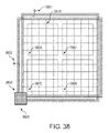
- FIG. 38 is a top view of another embodiment of the control system, designed to control larger arrays of distributed thrusters, than the control system in FIG. 34 .
- FIG. 39 is top view of another preferred embodiment of the control system, designed to control larger arrays of distributed thrusters than the control system in FIG. 38 .
- FIG. 40 a is a top view of another embodiment of the present disclosure, showing primary and secondary affected areas when the control system activates the target area.
- FIG. 40 b is a cross sectional view of the embodiment shown in FIG. 40 a , with intersecting power lines located on the heated side of the device
- FIG. 40 c is another cross sectional view of the embodiment shown in FIG. 40 a , with intersecting power lines on each side of the device.
- FIG. 41 a is a top view of another embodiment of the present disclosure with an electrical and or thermal insulator.
- FIG. 41 b is a cross sectional view of the embodiment shown in FIG. 41 a , with intersecting power lines located on the heated side of the device.
- FIG. 42 a is a top view of a grid structure for an array of distributed thrusters which includes a power supply line and a plurality of branch lines at the power line intersection point, to be used with the control system.
- FIG. 42 b a top view of a middle insulating layer placed on top of FIG. 42 a.
- FIG. 42 c is a top view a grid structure of a power supply line and a plurality of branch lines that is placed on top of FIG. 42 b and creates a plurality of target points from a single power line intersection point to be used with the control system.
- FIGS. 43 and 44 are schematic diagrams for creating a temperature gradient.
- FIG. 45 is a plot showing a useful rise and fall in temperature in a device having a temperature gradient.
- FIG. 46 is a top cross-sectional view of a plurality of thruster regions arranged in horizontal and vertical rows in accordance with the present disclosure.
- FIG. 47 is a top cross-sectional view of a plurality thruster regions showing the heating effect of adjacent regions when a thruster region is activated.
- FIG. 48 illustrates an activation sequence for temperature gradient devices among a plurality of temperature gradient devices in accordance with the present disclosure.
- FIG. 49 shows a perspective view of a conventional quad rotor.
- FIG. 50 shows a top view of a device with distributed micro-thrusters.
- FIG. 51 shows a side view of the device of FIG. 50 .
- FIG. 52 shows a top view of a vehicle with distributed micro-thrusters.
- FIG. 53 shows a side view of the vehicle of FIG. 52 .
- FIG. 54 is a top view of a further vehicle with distributed micro-thrusters.
- FIG. 55 is a side view of the further vehicle of FIG. 54 .
- FIG. 56 is a top view of an additional vehicle with distributed micro-thrusters.
- FIG. 57 is a front view of the additional vehicle of FIG. 56 .
- FIG. 58 is a top view of another vehicle with distributed micro-thrusters to augment the vertical lift and a plurality of engines to provide the forward thrust.
- FIG. 59 is a side view of the other vehicle of FIG. 58 .
- FIG. 60 is a flow chart of an exemplary control method using micro-thrusters.
- FIG. 61 is a flow chart of another exemplary control method using micro-thrusters.
- one example of distributed thrusters is an apparatus described herein that may be referred to as a Nano Molecular Solid-state Electrodynamic Thruster (“NMSET”).
- NMSET Nano Molecular Solid-state Electrodynamic Thruster
- the basis of operation of NMSET makes it possible to apply NMSET in the fields of, for example, propulsion, adhesion, compression and refrigeration, depending on the manner in which an NMSET is employed.
- NMSET and related distributed thrusters devices provide lightweight, compact, energy-efficient creation of a gas pressure differential with adjustable flow velocity.
- distributed thrusters such as NMSET can offer one or more of the following improvements in the field of gas propulsion:
- Lightweight Electrically driven distributed thrusters, may make use of photovoltaic thin films, in which case fuel load vanishes. Furthermore since each thruster in a distributed thrusters system creates a local gas pressure difference, this local effect may require fewer and or lighter apparatuses to maintain the structural integrity of such gas propulsion system, than what would be normally required in a non-distributed gas propulsion system that generates the same gas flow volume. 3.
- Scalability Conventional gas propulsion systems cannot be easily scaled: optimal turbojets for small aircrafts are not scale reductions of optimal turbojets for large aircrafts. Distributed thrusters are easier to scale as scaling primarily changes the quantity of thrusters while leaving the individual thruster dimensions mostly intact. 4.
- distributed thrusters such as, for example, NMSET
- the process can be reversible, as the only step required to reverse the adhesion is to cut power to the system in some embodiments.
- Using such a system can provide further benefit over electrostatic adhesion in that such a system does not require a material to be adhered to be flat or conductive, and does not leave behind residue. Compared to other mechanical adhesion processes, using such a system may not require a surface being adhered to be pretreated.
- distributed thrusters such as, for example, NMSET
- can be arranged to drive gas flow through a surface all or part of a pressurized vessel may function to provide gas compression.
- separated pumping and pressurized containment may not be required.
- the action of such a system generally occurs over a short distance, it is possible, in some embodiments, to use such a system as a highly compact compressor by stacking multiple stages of distributed thrusters.
- Conventional gas propulsion systems generally operate over length scales of centimeters and sometimes meters. Thus, stacking conventional propulsion systems tends to be a complex and expensive proposition.
- distributed thrusters can be packaged to operate over smaller scales, down to, for example, micrometers.
- the versatility of such systems means that such a system can be readily adapted to function as a high-pressure pump, a standard atmospheric pump, or with a sufficient number of stages, as a high vacuum pump.
- NMSET and some related devices described here may be thought of as functioning by reducing entropy in gas in contact with the system.
- such device may add energy, in addition to the energy lost through inefficiencies in the system, e.g. thermal energy, to the gas.
- the geometry of NMSET and some related devices can affect gas flow direction and convenience of use.
- NMSET and some related devices may be further distinguished from previous thermal transpiration devices and the like by the combined application of scale parameters, materials having advantageous molecular reflection properties, geometries, design, construction and arrangement of elements that provide significant increase in efficiency, and or capabilities to operate at higher ambient pressures and/or produce higher flow rates. Described herein are various exemplary embodiments of NMSET with discussion of these and other parameters that, in preferred embodiments, can create a strong gas flow in a particular direction with minimal thermodynamic loss, and or operate at higher ambient pressures and or produce higher flow rates.
- Reduction of entropy in a gas by NMSET may be represented by a transformation A in the momentum space k of the gas.
- A can be expressed in a matrix once a set of suitable bases is chosen for the momentum space k. If the expectation value of the transformed momentum space Ak is nonzero, the NMSET receives a net momentum in the opposite direction of the expectation value due to the conservation of momentum.
- NMSET may be optimized for more efficient functioning.
- the geometry of NMSET affects the transformation matrix A.
- a geometry that produces a matrix A essentially equal to an identity matrix I does not create a net momentum bias (i.e. will not make the transformed momentum space Ak have a nonzero expectation value). Rather, gas vortexes may be generated.
- Geometries that result in larger eigenvalues of A tend to imply a more efficient function, e.g., that more momentum is carried by gas particles moving in a particular direction.
- the heat pump 100 comprises an upper layer 101 and a lower layer 102 .
- a Cartesian coordinate system can be referenced with a y-axis pointing from the lower layer 102 to the upper layer 101 .
- a temperature differential can be established by a Peltier device (not shown) between the layers or any suitable means such that the upper layer 101 is colder than the gas and the lower layer 102 is hotter than the gas.
- the heat pump 100 has 100% Carnot cycle efficiency. However, other efficiencies are contemplated. In this case, the heat pump 100 will not transfer net heat into the gas.
- Transformation caused by the heat pump 100 to the momentum space k of the gas can be expressed by a Hermetian matrix A.
- a gas particle molecule or atom
- the gas particle rebounds off at a higher velocity than before the collision.
- the gas particle collides with the upper layer 101 , assuming the collision is diabatic, the gas particle rebounds off the upper layer 101 at a reduced velocity than before the collision.
- the heat pump 100 feels a net force in the y direction. In other words, the lower layer 102 heats and thus increases pressure of the gas below the lower layer 102 , while the upper layer 101 cools and thus decreases the pressure of the gas above the upper layer 101 .
- the pressure difference exerts a force on the heat pump 100 in the y direction.
- the transformed momentum space Ak becomes skewed preferentially in the ⁇ y direction, i.e., the expectation value p of the transformed momentum space Ak is nonzero and points to the ⁇ y direction.
- the heat pump 100 gains a momentum ⁇ p to conserve the total momentum of the closed system.
- Surface area of the heat pump 100 is surface area of its convex hull.
- NMSET uses energy to reduce entropy on some device surfaces and transfer reduced entropy to a gas in contact with the surface.
- the device can optionally donate energy to the gas by raising the gas temperature.
- the function of NMSET may be therefore divided into three areas: the means by which entropy on surfaces of the device is reduced, the means by which the reduced entropy is transferred to the gas, and the optional means other than the inefficiency of the Carnot cycle of the heat pump by which the gas temperature is increased.
- a temperature differential between layers of material or more precisely, between two opposing surfaces is generally required for NMSET or related device to operate.
- a temperature differential can be established in a solid-state electrodynamic mechanism, i.e., the “SE” of NMSET.
- SE solid-state electrodynamic mechanism
- the devices and methods described here are not limited to electronic or purely solid state devices.
- a temperature differential may be established by conduction of heat from combustion using a fluid coolant, exothermic chemical reaction, or other chemical source.
- a temperature differential may be established by simple resistive heating, by the Peltier effect, by thermionic emission, by the thermo-tunneling enhanced Peltier effect, or by any other suitable means, such as explained below.
- a means by which the temperature differential is established between two objects can be phenomenologically described by two characteristics: entropy-reduction (heat transfer between the two objects), and diabaticity (total heat transfer between environment and the two objects).
- the Peltier effect can be used to establish a temperature differential.
- the Peltier effect occurs when an electric current is applied through a loop composed of two materials with different Peltier coefficients joined at two junctions. Depending on the direction of the electric current, heat flows from one junction to the other, causing a temperature differential to be established between the junctions.
- the Peltier effect can be understood as follows: Heat capacity of charge carriers in a material is characterized by the Peltier coefficient ⁇ , which is the amount of heat carried per unit charge carriers in the material. When an electric current/flows through a junction of material A with Peltier coefficients ⁇ A and material B with Peltier coefficient ⁇ B , the amount heat carried by charge carriers to the junction in a unit time is I ⁇ ( ⁇ A ⁇ B ).
- Peltier effect reduces entropy locally and is adiabatic. Assuming Joule heating and or Carnot cycle inefficiencies can be ignored, in the Peltier effect, heat is transferred from one junction to another, but no heat is added into the loop of the two materials. This entropy reduction can provide for advantages in the stackability of NMSET and related devices. Consequently, the Peltier effect lends itself particularly well to some embodiments.
- a power source drives an electric current between two surfaces.
- Charge carriers such as electrons and/or holes carry heat as they flow in the electric current, and thus create a temperature differential between the two surfaces. Entropy is reduced as the temperature differential is established.
- Phonon flow reduces the temperature differential established by the Peltier effect. If phonons are permitted to flow freely (i.e., infinite thermal conductivity or zero heat capacity), their flow will cancel the temperature differential established by the Peltier effect. Efficiency of the Peltier effect can be increased by reducing electrical resistance and thermal conductance.
- thermo-tunneling enhanced Peltier effect (or thermotunnel cooling).
- FIG. 6 shows a diagram of the thermo-tunneling enhanced Peltier effect. Charge carriers 601 can tunnel through a vacuum gap 602 .
- thermo-tunneling enhanced Peltier effect is generally only significant at high temperatures or voltages, unless enhanced by choice of surface geometry and materials that can restrict behavior of charge carriers near the vacuum gap and increase tunneling probability.
- suitable surface coatings and structures can function as a filter that do not allow low energy states of charge carriers but only high energy states of charge carriers near the vacuum gap.
- a temperature differential can be created and maintained by field-enhanced thermionic emission.
- Thermionic emission is a heat-induced flow of charge carriers over a potential-energy barrier.
- the charge carriers can be electrons or ions (i.e., thermions).
- the potential-energy barrier acts like a dam, in that it withholds carriers with thermal energy less than its height and allows carriers with thermal energy greater than its height to flow over. When the overflowing carriers pass the potential-energy barrier, heat is carried away with them. The carriers left behind the potential-energy barrier re-thermalize (redistribute in energy) to a lower temperature.
- Thermionic emission typically requires an operating temperature of several hundred degrees Celsius so that a non-negligible fraction of the carriers has thermal energies great enough to overcome the potential-energy barrier.
- An electrical field can assist thermionic emission by reducing the height of the potential-energy barrier and reducing the required operating temperature.
- a temperature differential in NMSET or related device can also be established by using resistive heating (explained below) and/or by suitable chemical processes.
- some cooling means can also be provided, such as a heat sink exposed to atmosphere. No matter what cooling means is used, the temperature differential is more pronounced if warmer surfaces of the device are not cooled as efficiently as cooler surfaces, which can be achieved, for example, by thermal insulation.
- the production of net thrust may be thought of as the transfer of the reduced entropy from an established temperature differential to a gas.
- a temperature differential between a hot and a cold layer can be established by a suitable means such as the Peltier effect.
- a suitable means such as the Peltier effect.
- Particles of the gas will impact the hot and cold layers with equal probabilities, and their interaction with these layers will have consequences on local momentum space of the gas near surfaces of the hot and cold layers.
- the local momentum space of the gas very close to a surface of the hot and cold layers has nonzero expectation value when the gas and the surface have different temperatures.
- the weighted sum of expectation values of local momentum spaces of the gas is nearly zero, which results in almost no net thrust.
- the weighted sum of expectation values of local momentum spaces of the gas can be non-zero, which leads to a net thrust.
- FIG. 1 A trivial example of an arrangement that has non-zero net thrust is shown in FIG. 1 , as described above.
- This geometry is not very efficient because macroscopic convective gas flows and vortex formation increase the entropy and limit the amount of useful work.
- Exemplary convective gas flows 120 , 130 are shown in FIG. 2 .
- Gas at ambient temperature 110 flows towards the cold layer 101 and gets cooled. Cooled gas flows 120 away from the cold layer 101 and around the edge of the heat pump 100 towards the hot layer 102 . Heated gas flows 130 away from the hot layer 102 .
- the heat pump 100 can have at least one through hole between the layer 101 and 102 .
- Gas spontaneously flows from the layer 101 to the layer 102 through the hole which enables higher heating rate of the gas.
- Such preferential flow of gas is referred to as thermal transpiration.
- thermal transpiration causes the gas to flow from the layer 101 to the layer 102 through the hole, if the following equation is satisfied:
- thermodynamic equilibrium can be achieved approximately in the mean free time (the time it takes a gas particle to travel the mean free path).
- the characteristic scale of individual features of NMSET and related devices may be nanoscale, i.e., the “NM” of NMSET.
- NM the characteristic scale of individual features of NMSET and related devices
- the methods and devices described here are not limited to nanoscale embodiments.
- the mean free path parameter is dependent on gas density so that in some embodiments and uses, larger scale features may be employed.
- pluralities of NMSET and related device elements can be combined to provide action over a large surface.
- distributed thrusters such as NMSET may advantageously be arranged in arrays and or arrays of arrays to provide directed movement of gas over across large surfaces, for example, as illustrated in FIGS. 15, 16 and 17 .
- FIG. 18A illustrates a cross sectional view of an array of staged distributed thrusters such as NMSET arrangements 1800 .
- Each staged arrangement 1800 is composed of stages 1810 , 1820 , 1830 of in the form of concentric half-spheres containing arrays of distributed thrusters such as NMSET 1840 , 1850 , 1860 illustrated in blow-up in FIGS. 18B-18D .
- Individual distributed thruster apertures 1845 , 1855 , 1865 in each stage increase in optimal size and thickness in accordance with the decreasing ambient pressure that would be experienced at each previous stage in operation.
- Box 300 comprises two planar hot walls 302 parallel to each other, and two planar cold walls 301 parallel to each other and perpendicular to the hot walls 302 . If the box 300 is comparable in size to the mean free path of the gas particles therein and the walls 301 and 302 are perfectly specular, the gas particles can reach thermal equilibrium with the cold walls 301 and the hot walls 302 independently. This is because surface normals of the walls are only shared between the two cold walls 301 or between the two hot walls 302 , but not between a cold wall 301 and a hot wall 302 .
- Knudsen numbers are usually not perfectly specular.
- specular surface properties exist very strongly in some materials so that there are angles for which convective flows in corners may be reduced. This effect is generally observed when the Knudsen numbers are large, which is a preferred condition for NMSET and related devices, particularly in nanoscale embodiments.
- the Knudsen number (Kn) named after Danish physicist Martin Knudsen (1871-1949), is a dimensionless number defined as the ratio of the molecular mean free path to a representative physical length scale.
- the representative physical length scale is taken to be the order of magnitude of the aperture diameter of the device, i.e., the representative physical scale length is, for example, a nanometer if the aperture is measured in nanometers, and a micrometer if the aperture is measured in micrometers.
- the Knudsen number is preferably greater than 0.1, or greater than 1, or greater than 10.
- Performance of NMSET with a specific geometry can be simulated by a Monte-Carlo method for optimization.
- a simulation for NMSET or related device with any given geometry starts with a group of gas particles with random initial positions and momenta around the device. Positions and momenta of these particles after a small time interval are calculated from the initial positions and momenta, using known physical laws, parameters such as temperature, pressure, chemical identity, geometry of the device, interaction between surfaces of the device and the gas particles.
- the simulation is run through a chosen number of iterations and simulation results are analyzed.
- the geometry of the device can be optimized using simulation results.
- a device is constructed using the results of the simulation analysis.
- a simulation can be represented in the following table:
- a perturbation model M is evolved through a number (k) of iterations.
- M is initialized to an empty set, indicating no solution knowledge.
- a loop is started in which the search parameters generate an arbitrary element from the definite search space P and the prior learned knowledge M is used to perturb P.
- the specific algorithm used to perturb as an implementation detail.
- M should ideally be identical among all nodes, but this is not necessary due to the inherently stochastic nature of the process.
- the step of EVOLVE_MODEL which actually runs the Monte-Carlo simulation is the most computationally expensive of all by far and offers a lot of time to synchronize M.
- parameters depend on the environment.
- the parameters that the user can specify include the following:
- the Monte-Carlo simulation can be run with periodic bounds in all axes.
- particles encountering the periodic bound are stochastically thermostatted according to temperature and pressure settings in order to simulate ambient conditions.
- particle velocities are unmodified in order to simulate a periodic ensemble of identical device assemblies along that direction.
- the simulation may be run in two dimensions to reduce the computational complexity of the simulation.
- a three dimensional simulation should give similar results where the modeled device has cylindrical symmetry. Note that in general, a simulator does not have to use the periodicity as indicated here and may not specify any boundaries at all; they are only defined as a computational convenience.
- potential device geometries can be evaluated in consideration of the conditions under which a device will be used and known surface reflection properties of the material from which it will be constructed. Geometrical parameters can be optimized by analyzing results from simulation before the geometry is actually used in manufacture of NMSET and related devices.
- FIG. 19 shows an embodiment of NMSET or related device 1900 with a straight geometry.
- the device 1900 comprises a hot layer 1902 and a cold layer 1901 .
- the terms “hot layer” and “cold layer” mean that these layers have a temperature difference therebetween, not that the “hot layer” is necessarily hotter or the “cold layer” is necessarily colder, than a gas that NMSET or related device is immersed in.
- At least one straight through hole 1910 extends through all layers of the device 1900 and preferably has a similar cross-sectional shape and size for each set of layers.
- the straight through hole 1910 can have any cross-sectional shape such as circular, slit, and comb.
- a total length 1910 L (i.e. a distance from one entrance to the other entrance) of the straight through hole 1910 is up to 10 times, up to 5 times or up to 2 times of the mean free path of a gas in which the device 1900 is immersed.
- the mean free path of air at the standard atmosphere pressure is about 55 nm. At higher altitude, the mean free path of air increases.
- the total length 1910 L is preferably not greater than 1500 nm, and depending on application more preferably not greater than 550 nm, not greater than 275 nm or not greater than 110 nm.
- a temperature differential between the hot layer 1902 and the cold layer 1901 is preferably at least 0.5° C., more preferably at least 30° C., more preferably at least 50° C., and most preferably at least 100° C.
- the hot layer 1902 and the cold layer 1901 may be separated by a gap therebetween for thermal isolation.
- the gap preferably is a vacuum gap and/or contains a thermal insulator.
- the gap contains a plurality of thin pillars made of a good thermal insulator such as silicon dioxide.
- the device 1900 has preferably at least 10 straight through holes per square centimeter.
- a total perimeter length of all the straight through holes of the device 1900 per square centimeter is preferably at least two centimeters.
- FIG. 7 shows an embodiment of an NMSET or related device 700 with a parabolic geometry.
- alternating hot layers 702 and cold layers 701 are stacked.
- each hot layer 702 and cold layer 701 has a straight through hole. All the holes are aligned.
- the hole in each hot layer 702 has the similar size as the hole in the cold layer 701 immediately above, and is smaller than the hole in the cold layer 701 immediately below.
- Each cold layer 701 is colder than its immediate adjacent hot layers 702 and each hot layer 702 is hotter than its immediate adjacent cold layers 701 .
- a surface 702 a of each hot layer 702 which has a surface normal in the ⁇ y direction, is exposed.
- NMSET adiabatic or isobaric, but not both.
- FIG. 8 An approximation of gas flow in NMSET or related device with the parabolic geometry is shown in FIG. 8 .
- the momentum space of the gas is skewed such that the expectation value of the momentum points to the ⁇ y direction.
- the NMSET with the parabolic geometry may not suffer in its efficiency from the gas undergoing a change in volume, as long as the amount of heat added to the gas is sufficient to prevent the formation of vortexes.
- a device suffers in its efficiency from higher total entropy, i.e., the eigenvectors of the momentum space of the gas are not as far apart if the gas has to expand, but supplying heat at small scales is typically easier than carrying it away.
- the triangular geometry detailed in FIG. 9 is a partial optimization of the parabolic geometry for adiabatic flows. In this case, the gas is not permitted to experience a sufficient expansion to trigger large-scale vortex generation. Furthermore, because the apertures do not change size, a triangular arrangement such as this one may be easily stacked.
- the momentum space of this triangular geometry is more efficiently biased, as is illustrated in FIG. 10 .
- the exposed hot and cold surfaces meet at preferably a 90-degree angle; however, a source of inefficiency arises when particles carry heat back and forth between surfaces across the center gap.
- FIG. 9 shows a stack 900 of NMSET or related device with the triangular geometry.
- Each device in the stack 900 comprises a hot layer 902 and a cold layer 901 of equal thickness.
- the temperature differential between the cold and hot layers 901 and 902 can be established by any suitable means such as the Peltier effect or any other heat pump.
- Each device has a through hole 903 .
- Each though hole 903 has approximately a 45° chamfer ( 9031 and 9032 ) on each entrance.
- the surface of the chamfers 9031 and 9032 is, for example, from 1.40 to 1.42 times of the thickness of the cold and hot layers 901 and 902 , not including modifications to the acute angles for structural considerations.
- the through holes 903 in all layers in the stack 900 are aligned.
- the temperatures of the hot layers 902 in a device in the stack 900 do not increase monotonically from one side of the stack to the other side.
- the temperatures of the cold layers 901 in a device in the stack 900 do not decrease monotonically from one side of the stack to the other side.
- each cold layer 901 is colder than its immediate adjacent hot layers 902 and each hot layer 902 is hotter than its immediate adjacent cold layers 901 .
- the hot and cold surfaces of the triangular arrangement may not come to a fine point.
- FIG. 11 shows a stack 1100 of NMSET or related device with a sawtooth geometry.
- Each device in the stack 1100 comprises a hot layer 1102 with a thickness of t h and a cold layer 1101 with a thickness t c .
- the temperature differential between the cold and hot layers 1101 and 1102 can be established by any suitable means such as the Peltier effect or any other heat pump.
- Each device has a through hole 1103 . In the illustrated device, each through hole 1103 has a chamfer 11031 at the entrance on the side of the cold layer 1101 , and a chamfer 11032 at the entrance on the side of the hot layer 1102 .
- An angle between the chamfer 11031 and a center axis of the through hole 1103 is ⁇ 1 ; an angle between the chamfer 11032 and a center axis of the through hole 1103 is ⁇ 2 .
- the sum of ⁇ 1 and ⁇ 2 is preferably from 75° to 105°, more preferably from 85° to 95, and more preferably from 88° to 92°.
- the ratio of t c to t h is substantially equal to the ratio of cotangent of ⁇ 1 to cotangent of ⁇ 2 .
- ⁇ 2 is preferably from 70° to 85°.
- the relationships of the chamfer angles described here are preferred limitations, not hard boundaries. In general for materials exhibit perfectly specular molecular reflection properties, the relationships of the chamfer angles can be slightly relaxed. For materials exhibit less than perfectly specular molecular reflection properties, the relationships shall be stringent.
- the chamfer geometries are preferably arranged so as to minimize shared bases.
- the surface normals of the specularly reflecting chamfer surfaces can thus preferably be orthogonal. Deviations from orthogonality can incur a penalty in efficiency as a cosine function. For engineering reasons, the hot and cold surfaces of the sawtooth arrangement may not come to a fine point.
- the through holes 1103 in all layers in the stack 1100 are aligned. Temperatures of the hot layers 1102 in each device in the stack 1100 do not increase monotonically from one side of the stack to the other side. Temperatures of the cold layers 1101 in each device in the stack 1100 do not decrease monotonically from one side of the stack 1100 to the other side. Each cold layer 1101 is colder than its immediate adjacent hot layers 1102 and each hot layer 1102 is hotter than its immediate adjacent cold layers 1101 .
- the sawtooth geometry shown in FIG. 11 offers an improvement over the triangular geometry in that all hot layers 1102 are preferably oriented in nearly the same direction (i.e., ⁇ 2 is preferably nearly 90°). This reduces direct interaction between hot and cold layers 1102 and 1101 across the through hole 1103 , and improves overall efficiency.
- the sawtooth geometry is capable of reducing the entropy in the gas (and thereby causing it to do more work) more efficiently than the triangular geometry.
- the momentum space of this sawtooth geometry is more efficiently biased than the momentum space of the triangular geometry, as is illustrated in FIG. 12 .
- device slices on opposite sides of a cross section have a magnitude of 1/ ⁇ square root over (2) ⁇ in the y axis because their separation angle 90 degrees. This limits the efficiency of entropy reduction, as some of the entropy is going to be neutralized in direct inter-surface interaction.
- the hot layers 1102 not only share no basis with the adjacent cold layers 1101 , but also share very little basis with hot and cold layers across the through hole 1103 . This combined property makes the sawtooth geometry more efficient than the triangular geometry.
- FIG. 4 shows net forces the layers of the stack 1100 (sawtooth geometry) experience.
- low pressure is generated at the entrance aperture (upper aperture in FIG. 4 ) which in turn generates a corresponding low-pressure region above the stack 1100 , and a high-pressure region below the stack 1100 .
- Gas particle velocities of the stack 1100 resulting from the gas particle collisions are shown in FIG. 5 .
- each element in the device geometry acts both as a particle director and as the entropy reducer.
- the hot and cold plates are made of materials with different Peltier coefficients. Electrical current is made to flow between the cold and hot plates. This flow of current carries with it Peltier heat, establishing the temperature differential necessary to operate the device.
- piezoelectric spacers can be disposed between device elements to maintain the separation gaps therebetween.
- FIGS. 13 and 14 A cross section of NMSET or related device according to an embodiment with an internal Peltier arrangement is detailed in FIGS. 13 and 14 . All hot layers 1302 are connected. All cold layers 1301 are connected. Electric current flows through a Peltier device interposed between the cold and hot layers to establish a temperature differential. The thinner the layers are, the higher the electric current is necessary.
- NMSET or related device with the internal Peltier arrangement can make it easier to reduce the size of the device.
- a single stack such as the one shown in FIG. 14 can be fully functional to generate thrust.
- NMSET or related device with the internal heat pump are further suitable for use in microelectromechanical systems (MEMS) that emphasize the highest degree of granularity.
- MEMS microelectromechanical systems
- the temperature differential can be generated by field-enhanced thermionic emission. As shown in FIG. 19 , an electrical field can be established between the layers 1901 and 1902 such that charge carriers thermally emitted from the cold layer 1901 carry heat from the cold layer 1901 to the hot layer 1902 .
- the temperature differential can be generated by a heat pump, such as a Peltier device external to NMSET or related device.
- a heat pump such as a Peltier device external to NMSET or related device.
- This Peltier device arranged in a checker board fashion is thermally coupled to NMSET or related device stack 1500 via interface layers 1510 and 1520 as detailed in FIGS. 15 and 16 .
- a device with an external Peltier device has the benefit of separating the materials used to generate gas flow from the materials used to generate the temperature differential. From an engineering standpoint this may be desirable, as the materials suitable for a heat pump may not be suitable for microstructures, or vice versa. In addition, an external heat pump can be made larger and more efficient, and may require less current to establish a sufficient temperature differential.
- Piezoelectric spacers can be used between layers.
- Materials suitable for use in NMSET preferably are strong enough to mechanically withstand thermal expansion and contraction, and/or preferably have very small expansion coefficients. Otherwise, holes in the layers could become misaligned, which could reduce efficiency.
- a temperature differential is established by any suitable heat source and/or heat sinks.
- the heat sources might be field-enhanced thermionic emission, resistive heaters, chemical reaction, combustion, and/or direct illumination of bright light or other forms of radiation.
- FIG. 17 An illustration of such an embodiment is shown in FIG. 17 .
- a heating surface 1702 can be resistive heating material, or a material that can efficiently receive radiative heating.
- the external non-Peltier heat pump is convenient because it does not require a built in heat pump such as a Peltier device. For some applications, it may be convenient to direct the heating surface towards a source of radiation, such as the sun, rather than first converting radiation into electricity and drive a heat pump.
- a source of radiation may be directed toward a heat absorbing surface in thermal communication with the hot layer of NMSET or related device.
- a source of radiation may be directed toward a heat absorbing surface in thermal communication with the hot layer of NMSET or related device.
- more care is preferably taken to ensure that the NMSET or related device does not overheat.
- the capillaries 1750 illustrated in FIG. 17 provide an exemplary mechanism by which a heat sink could be provided; however, it is also possible for the heat sink to simply be a series of vanes, or any other suitable heat sinks.
- the external non-Peltier heat pump in FIG. 17 could be configured to provide a heat source through the capillaries 1750 .
- the heat source can be an exothermic chemical reaction, preferably one that does not generate too much pressure.
- NMSET and related devices may be constructed of a wide range of materials. In various aspects, properties of materials may be exploited in combination with desirable geometries.
- Specular reflection of gas molecules is a preferred property of the materials which form the gas-exposed surfaces of NMSET or related device, e.g. the heated and cooled surfaces which are in contact with flowing gas. Specular reflection is the mirror-like reflection of light, or in this case gas particles, from a surface. On a specular surface, incoming gas particles at a single incident angle are reflected from the surface into a single outgoing angle. If the incoming gas particles and the surface have the same temperature, the incident angle and the outgoing angle with respect to the surface normal are the same. That is, the angle of incidence equals the angle of reflection.
- a second defining characteristic of specular reflection is that incident, normal, and reflected directions are coplanar. If the incoming gas particles and the surface are not at the same temperature and the reflection is diabatic (i.e. with heat exchange between the gas particles and the surface), the angle of reflection is a function of heat transferred between the surface and the gas particles.
- the degree of specularity of a material may be represented by a reflection kernel (such as the Cercignani-Lampis kernel) which is defined as the probability density function of reflected state of the gas particles per unit volume of the phase space. Details of the reflection kernel are disclosed in “Numerical Analysis of Gas-Surface Scattering Effect on Thermal Transpiration in the Free Molecular Regime”, Vacuum , Vol. 82, Page 20-29, 2009, and references cited therein, all of which are hereby incorporated by reference.
- a reflection kernel such as the Cercignani-Lampis kernel
- Individual hot and cold layers may also be constructed of one or more structural elements which can comprise structural materials, e.g. a means for conferring rigidity, thermal conductive material, e.g. a means for heat transfer to and from a temperature differential generating means, and atomic reflection material, e.g. means for providing a desirable reflection kernel properties.
- structural materials e.g. a means for conferring rigidity
- thermal conductive material e.g. a means for heat transfer to and from a temperature differential generating means
- atomic reflection material e.g. means for providing a desirable reflection kernel properties.
- individual hot and cold layers may be constructed of layered composites of such materials.
- materials suitable for construction of NMSET or related device can include titanium, silicon, steel, and/or iron. Titanium is light weight and possesses a hexagonal crystalline structure. Interfaces of titanium may be created at orthogonal angles without crystalline warping and therefore no stress limit. Material costs of titanium are high. Silicon is inexpensive and has well understood properties and processes for machining. The crystalline structure of silicon is diamond cubic. Steel is cheaper than titanium, possesses a cubic crystalline structure, and is highly resistant to gaseous intrusion. Iron is cheaper than steel and has a crystalline form which makes it suitable for application in NMSET and related devices.
- a method of manufacturing an NMSET or related device comprises: (a) providing a suitable substrate 2001 such as, for example, amorphous silicon, crystalline silicon, ceramic, etc., the substrate preferably having a thickness of 500 to 1500 microns; however thinner and thicker substrates are possible; (b) depositing a first layer 2002 , a mostly sacrificial layer, preferably an electrical insulator, such as, for example, silicon dioxide, the first layer 2002 preferably having a thickness of 200 nm to 50 microns, however thinner and thicker layers are possible. Furthermore, depending on the area of the substrate window 2001 a , it is advantageous for this layer to have a tunable stress level.
- a suitable substrate 2001 such as, for example, amorphous silicon, crystalline silicon, ceramic, etc.
- Such layer can be made of, for example, wax, photoresist, or silicon dioxide substrate attached to the fifth layer 2006 via thermal release tape, the sixth layer 2007 preferably having a thickness of 500 to 1500 microns, however, other thicknesses are contemplated; (j) forming through holes 2001 a in the substrate 2001 by photolithography and etching the substrate 2001 , such that at least one discrete island of the first layer 2002 is exposed therein, the through holes 2001 a having any suitable shape such as, for example, hexagons, squares and circles, the through holes 2001 being arranged in any suitable pattern such as, for example, a hexagonal grid, square grid and a polar grid; (k) removing exposed discrete islands by etching until portions of the fourth layer 2005 there above are exposed; (l) removing exposed portions of the fourth layer 2005 by etching until portions of the fifth layer 2006 there above are exposed; (m) removing exposed portions of the fifth layer 2006 by etching; (n) partially removing the fourth layer 2005 by etching laterally such that the second layer 2003
- a method of manufacturing an NMSET or related device comprises: (a) providing a suitable substrate 2101 such as, for example, amorphous silicon, crystalline silicon, ceramic, etc., the substrate preferably having a thickness of 500 to 1500 microns; however thinner and thicker substrates are possible; (b) depositing a first layer 2102 , a mostly sacrificial layer, preferably an electrical insulator such as, for example, silicon dioxide, the first layer 2102 preferably having a thickness of 50 nm to 1000 nm; however thinner and thicker layers are possible. Furthermore, depending on the area of the substrate window 2101 a , it is advantageous for this layer to have a tunable stress level.
- a suitable substrate 2101 such as, for example, amorphous silicon, crystalline silicon, ceramic, etc.
- FIG. 22 is a side cross-sectional view illustrating a thermal transpiration device, such as NMSET or related device, shown generally at 2204 .
- the thermal transpiration device includes a cold side membrane 2202 and a hot side membrane 2201 , with a thermal insulator 2200 provided in between.
- the thermal insulator 2200 may be formed of a vacuum, which can be achieved, for example, via the Venturi effect.
- the thermal transpiration device 2204 includes a thickness 2203 defined by the cold side membrane 2202 , the thermal insulator 2200 and the hot side membrane 2201 .
- FIG. 23 is a side cross-sectional view illustrating the operation of a thermal transpiration device, shown generally at 2309 .
- the device 2309 includes a hotter layer 2301 , a colder layer 2302 , with a thermal insulator 2300 provided there between. Apertures 2308 are formed in the device 2309 in a manner as previously described.
- the thermal transpiration device 2309 includes a thickness 2303 defined by the colder layer 2302 , the thermal insulator 2300 and the hotter layer 2301 .
- the thermal insulator 2300 can be formed of a vacuum, which can be achieved, for example, via the Venturi effect.
- Colder gas particles 2304 which have a mean free path (average distance traveled before hitting another particle) shown by radius 2305 , enter the aperture 2308 , or the edge thereof, and collide with other particles, thus exchanging energy.
- Hotter gas particles 2306 which have a mean free path shown by radius 2307 , collide into the hotter layer 2301 , thus gaining energy in the process and imparting a positive momentum force.
- the colder gas particles 2304 reduce the temperature of the hotter gas particles 2306 , which collide back into the hotter layer 2301 , thus gaining energy and imparting a positive momentum force and increased pressure on the hot layer 2301 .
- FIGS. 24 and 25 are respective side and top cross-sectional views of a thermal transpiration device, shown generally at 2414 , with one extended layer having angled walls.
- the device 2414 includes a hotter layer 2401 and a colder layer 2402 , with a thermal insulator 2400 provided there between.
- the thermal insulator 2400 can be formed as a vacuum, which can be achieved, for example, via the Venturi effect.
- the total thickness of the device 2414 is indicated by reference number 2403 , and is defined by the colder layer 2402 , the thermal insulator 2400 and the hotter layer 2401 .
- Apertures 2408 are provided in the device 2414 , forming angled walls 2415 in the hotter layer 2401 , in a manner as previously described.
- the apertures 2408 , and/or edges thereof, aid in defining a hotter surface 2409 , a colder surface 2410 , an active area 2411 generally where thermal transpiration occurs, and a support area 2412 .
- the angle 2413 of the hotter surface 2409 is less than 90-degrees in order to form the angled walls 2415 .
- FIGS. 24 and 25 illustrate the extended layer having angled walls as being the hotter layer 2401 , one skilled in the art will appreciate that the colder layer 2402 could be implemented as the extended layer having angled walls as an acceptable alternative.
- FIGS. 26 and 27 are respective side and top cross-sectional views of a thermal transpiration device, shown generally at 2615 , with one extended layer having wet or dry etched walls.
- the device 2615 includes a hotter layer 2601 , a colder layer 2602 , with a thermal insulator 2600 provided there between.
- the thermal insulator 2600 can be formed as a vacuum, which can be achieved, for example, via the Venturi effect.
- the total thickness of the device 2615 is indicated by reference number 2603 , and is defined by the colder layer 2602 , the thermal insulator 2600 and the hotter layer 2601 .
- Apertures 2608 are provided in the device 2615 , and forming wet or dry etched walls 2614 in the hotter layer 2601 having a generally parabolic shape, in a manner as previously described.
- the apertures 2608 , and/or edges thereof, aid in defining a hotter surface 2609 , a colder surface 2610 , an active area 2611 generally where thermal transpiration occurs, a support area 2612 and wet or dry etched surfaces 2614 .
- Reference number 2605 indicates the mean free path radius of colder gas particles 2604 .
- Reference number 2607 indicates the mean free path radius (the average distance traveled before hitting other particles) of hotter gas particles 2606 .
- the colder gas particles 2604 enter the aperture 2608 , or the edge thereof, and collide with other particles, thus exchanging energy.
- the hotter gas particles 2606 collide into the hotter layer 2601 at the outer edge thereof or at the wet-etched surface 2614 , thus gaining energy in the process and imparting a positive momentum force.
- the colder gas particles 2604 reduce the temperature of the hotter gas particles 2606 , which collide back into the hotter layer 2601 thus gaining energy and imparting a positive momentum force and increased pressure on the hot layer 2601 .
- FIGS. 26 and 27 illustrate the extended layer having wet-etched walls as being the hotter layer 2601 ; one skilled in the art will appreciate that the colder layer 2602 could be implemented as the extended layer having angled walls as an acceptable alternative.
- FIG. 28 is a side cross-sectional view of a thermal transpiration device, shown generally at 2816 , with two extended layers having angled walls.
- the device 2816 includes a hotter layer 2801 and a colder layer 2802 , with a thermal insulator 2800 provided there between.
- the thermal insulator 2800 can be formed as a vacuum, which can be achieved, for example, via the Venturi effect.
- the device 2816 has a total thickness 2803 , defined by the colder layer 2802 , the thermal insulator 2800 and the hotter layer 2801 .
- Apertures 2808 are provided in the device 2816 , forming angled walls 2817 and 2818 in the hotter 2801 and colder 2802 layers, respectively, in a manner as previously described.
- the apertures 2808 , and/or edges thereof, aid in defining a hotter surface 2809 , a colder surface 2810 , an active area 2811 generally where thermal transpiration occurs, a support area 2812 for the hotter layer 2801 , and a support area 2815 for the colder layer 2802 .
- the angle 2819 of both the hotter 2809 and colder 2810 surfaces are less than 90-degrees in order to form the angled walls 2818 and 2817 , respectively. While the angles 2819 of the hotter 2809 and colder 2810 are shown in FIG. 28 as being approximately the same angle, the hotter 2809 and colder 2810 surfaces may be angled at different angles as an acceptable alternative depending on the embodiment.
- the total thickness of the active area of the device designed to operate in atmosphere should be less than 500 nm.
- the thickness between the hot and cold surfaces should be no greater than 100 nm.
- Such small thicknesses make the device extremely fragile and difficult to work with. If, for example, the device layers, or membranes, are made thicker in order to provide the required thickness for the stability and strength of the device, its overall thickness would increase to a point that it exceeds the ideal thickness, as discussed above.
- FIG. 29 is a cross-sectional view of the beginning construction of one embodiment of a thermal transpiration device, shown generally at in accordance with the present disclosure, which allows the thickness of a thermal transpiration device to be made thicker to enhance it durability and strength, while at the same time maintaining the thickness of the device in its critical area to within an ideal thickness range.
- the construction of the device is as follows. First, a silicon substrate layer 2916 is provided. A first metal layer 2917 of, for example, approximately 40 nm of aluminum, is deposited on the substrate 2916 .
- the deposition process may be evaporation, but other deposition methods may be used, such as, for example, sputtering, metal organic vapor deposition, etc.
- the first metal layer 2917 may be 40 nm of evaporated aluminum.
- a dielectric layer 2918 is deposited on top of the first metal layer 2917 .
- the dielectric layer 2918 must be low stress and may be formed of a plastic or inorganic non-electrically conducting film material.
- the film i.e., dielectric layer 2918
- the film may be, in particular, low-stress (e.g., 60 MPa) plasma enhanced chemical vapor deposition oxynitride that is 2 microns thick. Other thicknesses are also contemplated.
- An adhesion promoter layer 2919 may be deposited on dielectric layer 2918 to promote adhesion to the dielectric and or to act as an enhanced masking layer.
- Such material may be a chemical monolayer, such as HMDS, a thin film of organic resist, or a metal, in particular, 6 nm of chromium.
- the adhesion promoter layer 2919 may not be necessary on certain combinations of thin films and etching methods or etching chemicals.
- the device is then etched, as is conventionally known, using a mask 2920 of approximately 1.3 microns SPR-3012, for example, with an unmasked area 2921 .
- Etching may be achieved by depositing the photoresist layer, or mask, 2920 over the adhesion promoter layer 2919 , as is known to do by one of ordinary skill in the art.
- a photoresist is preferably Shipley SPR-3012; however, other photoresists may be utilized.
- the photoresist layer 2920 may then be exposed through a conventional mask to develop unmasked areas 2921 . Exposure can be made, for example, using an appropriate wavelength of light. Contact lithography may also be used as would be understood by one of ordinary skill in the art.
- the photoresist layer 2920 may be developed in a solution appropriate for that purpose to form the unmasked areas 2921 .
- a solution may be, for example, 0.26M tetramethylamonium hydroxide for SPR-3012 for approximately 60 seconds.
- the device is etched at the unmasked areas 2921 (See FIG. 29 ) to form etched areas 3022 .
- the etched areas 3022 are formed by etching into the adhesion promoter layer 2919 and the dielectric layer 2918 until portions of the first metal layer 2917 are exposed.
- the photoresist layer 2920 (see FIG. 29 ) is then removed.
- the adhesion promoter layer 2919 may be etched using a wet etch, such as, for example, a chromium etch 1020 from Transene, until the silicon substrate 2916 is exposed.
- the dielectric layer 2918 may be etched, for example, with a chemical that will not etch the first metal layer 2917 .
- the aqueous acid solution Silox Vapox II from Transene can be used.
- Other wet chemistries may also be used, or a dry plasma etch.
- FIG. 31 is a side cross-sectional view showing further etching of the thermal transpiration device shown in FIGS. 29-30 .
- Reference number 2916 is the silicon substrate
- reference number 2917 is the first metal layer
- reference number 2918 is the dielectric layer
- reference number 2919 is the adhesive promoter layer.
- the device namely, the etched area 3022 (see FIG. 30 )
- the etched area 3022 has been further etched to provide an etched area 3122 and under cut area 3123 .
- the first metal later 2917 is etched, and then portions of the substrate 2916 are etched.
- One method of forming the undercut areas 3123 portions of the substrate 2916 which are underneath the first metal layer 2917 are isotropically etched.
- the first metal layer 2917 may be etched with either wet or dry etching.
- aluminum for example, an aluminum etch in a reactive ion etcher with chlorine and argon at low pressure may be used to etch the first metal layer 2917 .
- An example of an etch for 40 nm of aluminum is 50 sccm BCl3, 20 sccm Cl2, 10 mTorr, with 300 W RF power.
- a wet or vapor etch can be used to etch the substrate 2916 , as long as the chemistry does not etch the first metal layer 2917 , the dielectric layer 2918 or the second metal layer 2919 .
- the silicon may be etched, for example, with the gas XeF2.
- the substrate 2916 may also be treated to remove boron.
- One exemplary method of such a treatment is to use a fluorine based reactive ion plasma under the conditions of 35 sccm CF4, 20 mTorr, and 300 W RF power.
- FIG. 32 is a cross-sectional view showing further formation of the thermal transpiration device shown in FIGS. 29-31 .
- a thin layer 3224 of silicon dioxide or another electrical insulator is provided over the device.
- the silicon dioxide layer 3224 can be, for example, approximately 2-10 nm thick. Thinner is generally better as long as there are few or no gaps in coverage, especially near the first metal layer 2917 .
- the layer 3224 of silicon dioxide is provided to control tunneling thickness.
- the layer 3224 can be added by evaporation, or other known techniques. For example, other methods, such as sputtering, plasma enhanced chemical vapor deposition, atomic layer deposition, etc., may be used as well, along with other materials.
- a second metal layer 3225 is provided over the silicon dioxide layer 3224 .
- the second metal layer 3225 may be a layer of metal, such as nickel or copper, and may be approximately 40 nm thick.
- the second metal layer 3225 may be formed by evaporation, but other methods may be used as well, such as, for example, sputtering or ion assisted deposition.
- the substrate 2916 is then mounted to a carrier substrate (not shown) with the thin film stack facing the carrier.
- the mount material could be, for example, a double-sided tape, such as Revalpha thermal release tape.
- other tapes and materials such as, for example, wax or photoresist, may be used as well.
- the remaining silicon substrate 2916 is then removed with, for example, an XeF2 vapor etch.
- the small portions of the silicon dioxide layer 3224 and the second metal layer 3225 formed in the etched portion of the substrate 2916 are removed with the substrate 2916 .
- Wet chemistry may also be used to remove the substrate 2916 , as long as it does not etch the first and second metal layers 2917 and 3225 .
- What is left, as shown in FIG. 33 are the islands 3127 formed by the first metal layer 2917 , the dielectric layer 2918 , the adhesion promoter layer 2919 , the thermo tunneling layer 3224 , and the second metal layer 3225 .
- the device is then sonicated to remove any Nickel plugs.
- the carrier substrate can be placed on a hotplate of sufficient temperature to aid in removing the device.
- control system In order to drive an object using distributed thrusters in a particular direction and or at a desired speed, a control system is needed.
- the control system is used to selectively activate and or adjust power levels to a distributed thruster or plurality of distributed thrusters to provide the desired force in the desired direction.
- a control system for controlling the operation of distributed thrusters may be constructed as a grid of elements (each containing one or more thrusters) fed by at least a redundant two dimensional network of power distribution wiring.
- the distribution network is constructed as a plurality of loops comprised of horizontal and vertical lines or wires that are coupled to a plurality of horizontal rows and vertical columns of thrusters.
- each row and column loop meet or intersect in at least four locations, but alternating topologies may be designed to balance redundancy, number of loops, and the granularity of addressing. Alternate topologies may have a different number of crossings.
- At least one power source may be supplied for each element in the grid or for a plurality of elements.
- One element may contain a plurality of thrusters.
- One terminal of the power source is connected to a horizontal line, and the other terminal of the power source is connected to a vertical line. This connection permits an element or group of elements to be addressed by connecting the terminals of a power source to the appropriate row and column.
- an electrical circuit is used to activate distributed thrusters by supplying and or regulating the amount of heat to the distributed thruster.
- An electrical circuit is formed by a loop comprised of the horizontal and vertical lines. Both ends of a given loop are driven at the same electrical potential. This means that a single cut anywhere in a given loop (as a result, for example, from damage to the array surface) will minimize a cascading loss of functionality.
- the heating or cooling caused by electrical circuit may be implemented by way of a heat pump, such as one driven by the Peltier effect using a Peltier slab.
- the wiring are on either side of the distributed thrusters, and in a resistance embodiment explained below, they may be only on the hot side. In further embodiments of distributed thrusters, other methods of powering the distributed thrusters can be used.
- FIG. 34 is a top view of one embodiment of a control system 3400 for an array 3401 of distributed thrusters 3402 in accordance with the control system.
- a plurality of distributed thrusters 3402 are arranged in a grid-like manner in parallel horizontal rows and parallel vertical columns.
- At least one power supply 3406 provides power to selected distributed thrusters 3402 using a first plurality of power lines 3404 and a second plurality of powers lines 3405 which are coupled to the distributed thrusters in each of the horizontal rows and in each of the vertical columns, respectively.
- a control unit 3403 controls the activation and or power levels of the selected power lines 3404 and 3405 for the desired thruster or group of thrusters.
- the power supply 3406 may be a battery and the control unit 3403 may be a central processing unit. Further, thruster 3402 may comprise a plurality of thruster devices.
- a NMSET device may comprise an apparatus operable to propel a gas where the apparatus comprises at least a first layer and a second layer arranged in a stack and means for heating and/or cooling the first and second layers to form a hot layer and a cold layer wherein the cold layer has a lower temperature than the hot layer, and at least one through hole in the stack.
- a surface of each hot layer is exposed in an interior of the through hole, a surface of each cold layer is exposed in the interior of the through hole, and an entire length of the active area of the through hole is up to 10 times of a mean free path of a gas in which the apparatus is immersed and/or is not greater than 1500 nm, as explained above.
- At least one through hole may have a straight geometry, a sawtooth geometry, a triangular geometry, a parabolic geometry, or any geometry that may be determined to be beneficial for the NMSET device, as explained above.
- FIG. 35 illustrates power lines 3504 and 3505 that meet at area 3506 to activate the distributed thruster's adjacent area 3506 .
- the control unit 3503 activates the distributed thruster's adjacent area 3506 by causing the power supply 3506 to provide electricity to power lines 3504 and 3505 .
- FIG. 36 illustrates a fault condition where there is an open circuit in power line 3605 .
- power line 3605 is associated with a vertical column of thrusters that are associated with the area around points 3608 . Because there is an open circuit 3607 in power line 3605 , the thrusters associated with the area around points 3608 cannot be activated due to this fault condition.
- redundant path connections are provided as illustrated in FIG. 37 .
- Power lines 3701 are coupled to the horizontal rows of thrusters and that power lines 3702 are coupled to the vertical columns of thrusters.
- a redundant path is provided to point 3706 in the event that a fault 3707 occurs in line 3705 as shown in FIG. 37 .
- Redundancy is provided by power lines 3705 and 3704 wherein the control unit 3700 reroutes electricity from the first to the second connection point of power line 3707 or the power line is internally looped to activate the thrusters near point 3706 .
- a fault detection device 3708 is provided to detect a fault condition in any one of the power lines as shown in FIG. 37 .
- the fault detection device 3708 is coupled to the power supply 3703 and control unit 3700 and which controls activation of an appropriate power line to compensate for, reroute, report and or replace the power line in which the fault condition is present.
- a capacitor bank voltage sensing technique may be used to detect a fault. By designing the capacitor bank to not discharge completely in a single pulse, and measuring the voltage charge before and after a power pulse has been sent to a thruster element or a group of thruster elements, it is possible to determine the power consumed by the thruster or group of thrusters and compare this to the expected power. If the drop is significantly smaller than expected, this is a sign of an open circuit; a significantly large drop indicates a short.
- In-line current sensing may also be used to detect a fault.
- a shunt resistor may be placed in series with the power distribution lines in order to measure the instantaneous current being drawn by the array. If the current is usually low, some cells may be open. If the current is excessively high, there is a short.
- the primary disadvantage of this method is that it increases the series resistance between the power supply and the thrusters by a small (but nonzero) amount.
- This method over sensing the capacitor voltage after a pulse is that it is possible to design a system fast enough (most likely at a few MHz level sampling rate) to respond in real time to a short circuit and abort the pulse before enough energy has been released to cause serious damage to adjacent thrusters from arcing, or to the power supply from rapid discharge and consequently overheating.
- This system may also be applied to a distributed thrusters operated in the continuous-duty mode.
- the overall thrust may be maintained by removing the damaged thrusters or section of thrusters from the firing sequence and operating the remaining undamaged thrusters or sections at a slightly increased duty cycle.
- An increase in duty cycle can only compensate for a maximum amount of damage to the system. If this threshold is exceeded, a reduction in available thrust is unavoidable; an array's control system can be designed to compensate for loss of thrust capacity on one side of a craft or other application using the distributed thruster by slightly reducing the thrust on the corresponding opposite panel to maintain a level trim.
- FIG. 38 is a top view of another embodiment of an exemplary control system, particularly useful for larger distributed thrusters systems and/or applications that can use a less granular control.
- This embodiment may be advantageous due to the decrease in the number of power and/or control lines, and/or the decrease in the required computing power, than what would normally be required for more granular control.
- the exemplary control system is showing an array of power supply lines 3801 and 3802 and sub power line 3810 that are used to activate sections of a group of distributed thrusters 3803 , 3804 , 3805 , and 3806 (shown in dotted line and which may further include a plurality of individual thrusters at the power line intersections).
- control unit 3800 may connect the power supply 3803 to an appropriate power line of power supply lines 3801 and an appropriate power line of power supply lines 3802 in order to cause electricity to flow in the corresponding sub power lines 3810 at and around the corresponding thruster or regions of thrusters in 3803 , 3804 , 3805 , 3806 .
- control unit 3800 can be designed to activate thrusters region 3803 and thrusters region 3805 or 3804 or 3806 simultaneously, sequentially, or in a desired pattern or for a desired effect by causing electricity to flow in the appropriate power lines of power supply lines 3801 , 3802 and sub power lines 3810 and through the inclusion of an additional microprocessor at the intersections of sub power lines with the power lines, and using a digital signal to communicate with those microprocessors.
- FIG. 39 is a top view of a further embodiment similar to that shown in FIG. 38 of an exemplary control system.
- FIG. 39 illustrates a plurality of power supply lines 3901 and 3902 and a plurality of sub-power supply lines 3910 that form a grid structure as shown.
- the control unit 3900 may connect the power supply 3911 to an appropriate power line of power supply lines 3901 and an appropriate power line of power supply lines 3902 in order to cause electricity to flow in the sub-power lines 3910 at and around the corresponding thruster or regions of thrusters 3903 .
- the control unit 3900 may activate any of distributed thrusters 3903 , 3904 , 3905 , 3906 , 3907 , 3908 , and 3909 in a group or individually.
- FIGS. 40 a , 40 b and 40 c shows an enlarged illustration of the embodiment of the control system shown in FIG. 34 .
- Power lines 4001 and 4002 are used to address the thruster regions that operate on temperature gradients 4006 around addressed point 4003 .
- point 4003 heats up with area 4004 being the primary area affected and area 4005 being the secondary area affected.
- FIGS. 41 a and 41 b shows the inclusion of a heat barrier 4117 , which may be in the form of a conductive pad, an insulator, a gap, or any other form of heat barrier as recognized by one of ordinary skill in the art.
- the heat barrier 4117 has the effect of changing the heat conductivity and isolating the conductive areas.
- the heat barrier 4117 is shown as a perimeter around the thruster regions 4108 that are adjacent a junction 4106 of power lines 4105 and 4104 , however the heat barrier 4117 may be configured differently based on a different desired effect.
- the thruster regions 4108 adjacent junction 4106 are activated and the heat barrier 4117 prevents other thruster regions outside of the shaded box area shown as 4119 from being inadvertently activated.
- FIGS. 42 a , 42 b and 42 c show the power lines or conductive structures of another embodiment of the control system.
- FIG. 42 a shows a top layer grid structure 4202 of conductive lines to be used for activating thruster regions, where power supply line 4200 is designed to be connected to a power supply and a plurality of branch lines 4201 are designed to be positioned in proximity to a plurality of thruster regions.
- FIG. 42 b illustrates an optimized middle layer showing insulators 4202 and resistors, temperature gradient generating device or other means of activating thruster regions 4203 to be used in between the grid structure shown in FIG. 42 a and further grid structure that will intersect the branch lines 4201 in FIG. 42 a at the thruster regions 4203 .
- FIG. 42 c illustrates the combination of FIGS. 42 a and 42 b , where the top layer of FIG. 42 a is placed over the middle layer of FIG. 42 b .
- FIG. 42 c shows power supply line 4200 and branch lines 4201 overlaid onto the thermo-resistive heating junctions formed by resistors 4203 or temperature gradient generating device or other means of activating thruster regions and insulators 4202 as in an embodiment of the control system, to control a plurality of target points from a single power line intersection point.
- FIG. 43 is schematic diagram of a device that can be used to create a temperature gradient in accordance with the present disclosure.
- the heat pump or thermal gradient device may be, but is not limited to driving a NMSET device.
- the device includes a colder layer 4301 of an electrically conductive material having a top surface 4302 and a bottom surface 4305 .
- a top surface 4306 of a hotter layer 4304 is closely proximate to and may be attached to bottom surface 4305 of colder layer 4301 directly or through a thermally and/or electrically insulating intermediate material depending on implementation.
- the hotter layer 4304 is made of or is a structure with sub-layers that include a layer of a resistive material that heats up through resistive or Joule heating when electrical current passes through it.
- a resistive material that heats up through resistive or Joule heating when electrical current passes through it.
- the colder layer 4301 might be of a material less subject to Joule heating in the operative locations.
- the difference in resistive, Joule heating characteristics can be accomplished through selection of materials, configuration (e.g., the hotter layer being thinner at the sites where heat is to be generated when compared to an opposing location of the colder layer so that the electron density in the hotter layer promotes Joule heating at a greater extent that the colder layer) or other factors that permit one layer to heat up to a greater extent or faster than an adjacent layer, or combinations thereof of these characteristics, depending on a particular embodiment.
- the hotter layer can be made up of surface wires that thin or become more narrow or otherwise have smaller in cross-section at sites where heating is desired, e.g., at a NMSET structure or groups of NMSET structures, such that the charge carrier density/resistance is greater at those sites, and Joule heating is more apparent.
- the colder layer can be a thicker, less resistive material having a broader area (e.g., cover the entire surface of the hotter layer) to reduce carrier density.
- the current in one layer promotes Joule heating, and in the other layer does not, at least not to the same extent of Joule heating in the one layer.
- the mechanism for passing current from one layer to the other can follow any suitable method or mechanism, such as quantum tunneling, semiconductor conduction
- the colder and hotter layers are P-type and N-type semiconductors forming a PN junction, with electrode formed thereon on opposing surfaces, transistors connected to address line, similar to the read/write and address lines of memory devices, that permit an adjacent electrode to heat on one surface, with the switch being much like the structure of an addressable memory site or pixel, but with the memory site or pixel structure being replaced with an electrode that thermally heats, or nearly any other type of structure that will selectively address thermal gradient devices or clusters of such devices.
- the hotter layer can have an input side and an output side in the same layer, wherein current passes through from one side to the other, resistively heating the hotter layer.
- This embodiment can produce heat at selected sites, and less so elsewhere, when the hotter surface is not entirely covered by an electrically conductive material, but rather has conductive lines, wherein the lines have characteristics that permit heating at selected sites, such as NMSET structures of groupings. That is, the lines can be large enough is cross-section to not heat, but at selected sites have a reduced cross-section to selectively heat upon application of current.
- electrical current passes from the top layer 4301 to the bottom layer 4304 .
- switch 4308 is in an open condition.
- no current flows through layers 4301 and 4304 .
- FIG. 44 showing the state where switch 4406 is closed.
- current from power supply 4407 flows through layers 4401 and 4402 .
- layer 4402 begins to heat because of its resistive characteristics, thus causing layer 4401 to heat as well.
- the heating of layer 4402 causes a temperature gradient 4405 to be created between top layer 4403 and bottom layer 4404 .
- switch 4406 is opened, current no longer flows through layers 4401 and 4402 .
- temperature gradient 4405 begins to diminish eventually to zero difference in temperature between surfaces 4403 and 4404 .
- FIG. 45 plots of the temperature increase of surface 4404 as current begins to flow when switch 4406 is closed. Temperature is plotted along the y-axis and time is plotted along the x-axis. Note that the temperature of surface 4404 in FIG. 45 rapidly rises as indicated by plot 4501 to an equilibrium temperature 4504 . The switch 4406 in FIG. 44 is then opened and current no longer flows, the temperature will begin to drop.
- the temperature of surface 4403 when switch 4406 is closed follows a similar but delayed pattern 4507 as the heat from layer 4402 begins to migrate toward surface 4403 through layer 4401 as indicated by plot 4502 .
- the temperature of surface 4403 continues to rise even slightly after the switch 4406 in FIG. 44 has been opened, to its equilibrium temperature 4505 .
- Reference number 4506 in FIG. 45 indicates the length of time that switch 4406 remained closed. If the length of time 4506 the switch 4406 remains closed exceeds the time it takes to reach equilibrium temperature 4504 , than the temperature of surface 4403 will continue to rise, until the temperature gradient 4503 vanishes.
- temperature gradient 4503 the temperature gradient between temperature 4504 of surface 4404 and the temperature 4505 of surface 4403 at a given time is represented in FIG. 45 as temperature gradient 4503 .
- FIG. 45 illustrates, it takes a finite amount of time for the temperatures of surfaces 4403 and 4404 to return to their ambient state after current stops flowing through layers 4301 and 4304 .
- the residual heat can cause problems if adjacent temperature gradient devices are in close proximity.
- FIG. 46 is a top cross-sectional view of a plurality of distributed thruster devices such as one operated by temperature gradient devices 4603 arranged in horizontal and vertical rows in accordance with another exemplary embodiment.
- Current flow is supplied to each device by a plurality of power lines 4601 and 4602 from a power and control unit 4300 in a matrix type manner.
- the control unit may be formed of a processor, particularly a programmable processor that can selectively actuate particular sites, as explained above with respect to control electronics at the active sites when the power lines operate like read/write and address lines to control adjacent control electronics at the active site, or simply by adding current to horizontal and vertical power lines such that at cross points enough current is present to create a temperature gradient.
- a source of electrical energy may be formed of a battery, or any other source of carriers, whether AC or DC, depending on implementation. Also, the section entitled “Fault Tolerant Control System”, above, is incorporated herein
- an adjacent temperature gradient device 4603 is activated before the first temperature gradient device 4603 is allowed to fully cool, the temperature gradient of the newly activated device may not be the expected gradient. Depending on the application, this may not be optimal.
- a temperature gradient device 4703 is activated by power lines 4704 and 4705 .
- the generated heat radiates to a primary area 4701 and further to a secondary area 4702 . Note that the radiated area encroaches upon other adjacent temperature gradient devices and could cause those devices not to produce the proper temperature gradient when they are activated. This potential problem can be mitigated or resolved by the selective activation of thermal gradient devices.
- control unit 4600 shown in FIG. 46 avoids activation of those temperature gradient devices that are adjacent previously activated temperature gradient devices for a predetermined period of time. Doing so allows the previously activated temperature gradient device to fully cool, or at least cool to a satisfactory temperature, so that no residual heat interferes with the operation of adjacent temperature gradient devices.
- the temperature gradient devices can be selectively addressed, either individually or in clusters, by read and address lines in a manner similar to the manner in which pixels on a digital display or memory sites in a memory array are addressed and controlled.
- FIG. 48 illustrates one embodiment of an activation sequence of temperature gradient devices in an array of temperature gradient devices in accordance with this embodiment.
- Reference number 4801 represents a temperature gradient device in an array of such devices as illustrated in FIG. 46 .
- Reference number 4802 represents an adjacent temperature gradient device, or an adjacent array of such devices.
- the pattern repeats as indicated by reference numbers 4803 - 4816 for a total of 16 temperature gradient devices, or arrays of such devices as illustrated, though of course in most embodiments involving NMSET devices there would be more.
- an activation sequence for individual or sets of temperature gradient devices can be determined which avoids or mitigates thermal interference from a previously activated adjacent device. This is so because enough time has elapsed for the previously activated adjacent device to sufficiently cool.
- temperature gradient device pairs 4801 , 4809 ), ( 4803 , 4811 ), ( 4805 , 4813 ) and ( 4807 , 4815 ) may be activated followed by pairs ( 4802 , 4810 ), ( 4804 , 4812 ), ( 4806 , 4814 ) and ( 4808 , 4816 ) without significant causing thermal interference to any previously activated adjacent devices.
- Other activation sequences will become known to those skilled in the art from a review of FIG. 48 .
- the disclosed embodiments can have many applications for creating and maintaining thermal gradients.
- the thermal gradient structures can be in heat pumps to drive distributed thrusters, and even more particularly distributed thrusters driven by NMSET of many forms and variations disclosed elsewhere herein.
- FIG. 49 shows a perspective view of a conventional quadrotor 4950 .
- the quadrotor 4950 is an aircraft that is lifted and propelled by four horizontally positioned rotors 4905 - 4908 .
- the quadrotor 4950 includes a common vehicle compartment 4900 , four engines 4901 - 4904 , and four rotors 4905 - 4908 .
- the rotors 4905 - 4908 of the quadrotor 4950 use fixed-pitch blades, whose rotor pitch does not vary as the blades rotate. Control of the quadrotor 4950 can be achieved by varying the relative speed of each rotor 4905 - 4908 to change the thrust and torque produced by each rotor 4905 - 4908 .
- Each rotor 4905 - 4908 produces both a thrust and torque about its center of rotation, and a drag force opposite the direction of flight. If the rotors 4905 - 4908 (e.g., all of the rotors) spin at a common angular velocity, with rotors 4905 and 4907 rotating clockwise and rotors 4906 and 4908 rotating counterclockwise, the net aerodynamic torque, and hence the angular acceleration about the yaw axis is zero (e.g., exactly zero).
- the yaw stabilizing rotor of conventional helicopters thus, may be eliminated in the quadrotor 4950 . Yaw, however, may be intentionally or unintentionally induced by mismatching the balance in aerodynamic torques (e.g., by offsetting the cumulative thrust commands between the counter-rotating blade pairs).
- Angular accelerations of the quadrotor 4950 about the pitch and roll axes can be generated separately without impacting the yaw axis.
- Each pair of blades of the rotors 4905 : 4907 or 4906 : 4908 rotating in the same direction controls one axis, either roll or pitch.
- Increasing the thrust for one rotor 4905 or 4906 while decreasing (e.g., simultaneously decreasing) the thrust for the other rotor 4907 or 4908 , respectively, can maintain the torque balance for yaw stability and can induce a net torque about the roll or pitch axis.
- Fixed rotor blades can be used to maneuver the quadrotor 4950 (e.g., in any direction) more precisely and faster than helicopters.
- the quadrotor design however is only slightly more precise and responsive than helicopters, and may not recover from damage to one of the rotors 4905 - 4908 .
- a flight control system for aircraft may use an array (e.g., a large array) of micro-thrusters, for example, an array that may include more than a threshold number of micro-thrusters (e.g., in the range of 10 5 to 10 9 micro-thrusters) and that may be disposed on one or more surfaces (e.g., control surfaces) of the aircraft.
- the micro-thrusters may generate thrust to either lift or lower the aircraft or may provide maneuvering thrust to quickly change the flight path.
- At least one region of the micro-thrusters may be mechanically moved or the power to the region corresponding to the micro-thrusters may be varied so that the difference in force or drag on the aircraft associated with the movement of the region or change in power to the micro-thrusters may cause the aircraft to move in the desired direction (e.g., in the desired flight path).
- FIGS. 50 and 51 show top and side views of a device 5050 with distributed micro-thrusters 5000 .
- the device 5050 may include a plurality of micro-thrusters (e.g., NMSET) 5000 , a main body 5002 and support structures 5001 .
- NMSET micro-thrusters
- the plurality of micro-thrusters 5000 may be coupled to (e.g., connected to) the main body 5002 of the device 5050 via the support structures 5001 .
- the plurality of micro-thruster 5000 may form one or more arrays embedded in a micro-thruster body 5010 such that a gas (e.g., atmospheric gas or other surrounding gas) may be propelled through the micro-thruster body 5010 by the plurality of micro-thruster 5000 to generate a force on the device 5050 .
- a gas e.g., atmospheric gas or other surrounding gas
- the plurality of micro-thrusters 5000 propels gas toward the main body 5002
- a force in a first direction may be applied to the device 5050 and when the plurality of micro-thrusters 5000 propel gas away from the main body 5002 , a force in a second direction (e.g., opposite the first direction) may be applied to the device 5050 .
- the plurality of micro-thrusters 5000 may provide a force in any direction to the device 5050 .
- the support structures 5001 may include a plurality of supports 5020 to space the micro-thruster body 5010 from the main body of the device 5050 such that the gap between micro-thruster body 5010 and the main body 5002 of the device 5050 may be uniform.
- the supports are shown as fixed and column-shaped and may not effect the flow of the propelled gas or may only have a negligible effect on the flow of propelled gas, it is contemplated that the supports or other such structures may be movable or may enable changes to the flow of propelled gas at the circumference of the device 5050 to enable movement or rotation of the device 5050 in any direction.
- micro-thruster body 5010 is shown as a circular section, it is contemplated that any shape of the micro-thruster body 5010 is possible.
- micro-thruster body 5010 is shown as larger than the main body 5002 , it is contemplated that the micro-thruster body 5010 may be any size relative to the main body 5002 and, for example, may be sized to generate a specified force on the device 5050 .
- the device 5050 may include: (1) an air-based vehicle, such as an aircraft or helicopter, among others; (2) a land-based vehicle such as a automobile, truck, van or motorcycle, among others; and/or (3) other mobile transportation devices such as a cart or fork-lift, among others.
- an air-based vehicle such as an aircraft or helicopter, among others
- a land-based vehicle such as a automobile, truck, van or motorcycle, among others
- other mobile transportation devices such as a cart or fork-lift, among others.
- the device may be used as propulsion systems for toys and games.
- the main body 5002 may contain a power generation or storage system 5025 and/or a power control system 5030 .
- the power control system 5030 may control the supply of power to the plurality of micro-thrusters (e.g., NMSET) 5000 to change the operating conditions of the micro-thrusters 5000 to vary the thrust produced by various regions.
- NMSET micro-thrusters
- an array of micro-thrusters 5000 may maneuver the device or vehicle 5050 in any direction (e.g., in all dimensions) by adjusting thrust produced by certain regions of the micro-thrusters 5000 .
- the device 5060 may rotate about an axis 5070 .
- the device 5050 may move in the direction opposite the flow of the gas.
- the micro-thruster body may be a control surface, for example, of a vehicle such as an aircraft, and may be made of lightweight material, for example, aluminum, and/or carbon fiber, among others.
- the control surface may be made of NMSET.
- FIGS. 52 and 53 show top and side views of a vehicle 5150 with distributed micro-thrusters.
- the vehicle (e.g., aircraft) 5250 may include a main body 5200 , wings 5201 and 5202 , horizontal stabilizers 5203 and 5204 and a vertical stabilizer 5205 .
- Micro-thrusters e.g. NMSET
- Micro-thrusters may be provided (e.g., embedded) in one or more of the wings 5201 and 5202 , the horizontal stabilizers 5203 and 5204 and/or the vertical stabilizer 5205 to enable: (1) the vehicle 5250 to move (e.g., without a conventional engine) using the micro-thrusters for both movement along the flight path and directional control.
- the wings 5201 and 5202 , the horizontal stabilizers 5203 and 5204 and the vertical stabilizer 5205 may include micro-thrusters covering (e.g., connected to, but separated from) or integral with (e.g, embedded therein) the control surfaces to form control surfaces which may direct or propel gas (e.g., air surrounding the control surface) to generate, for example, propulsion and/or lift and to provide for adjustment to the flight path.
- micro-thrusters covering e.g., connected to, but separated from
- gas e.g., air surrounding the control surface
- the micro-thrusters on the wings 5201 and 5202 may be used to generate propulsion, lift and/or maneuvering thrust. That is, the gas surrounding the upper side of each wing 5201 and 5202 may be propelled by one or more regions of micro-thrusters downward and toward the back of each wing 5201 and 5202 to generate both propulsion and lift.
- the thrust generated over each wing 5201 and 5202 may be controlled to produce a differential force (lift) on the vehicle 5250 which may control roll (e.g., rotation along the longitudinal axis 5160 ).
- each wing 5201 and 5202 may include a structure to cause the air surrounding the upper side of each wing 5201 and 5202 to vent at or near the back edge of each wing 5201 and 5202 in a direction to generate both propulsion and lift.
- a structure may include guide vents to provide thrust vectoring of the propelled gas.
- the micro-thrusters on the horizontal stabilizers 5203 and 5204 may generate maneuvering thrust. That is, the gas surrounding the upper side of each horizontal stabilizer 5203 and 5204 may be propelled by one or more regions of micro-thrusters downward to generate an upward maneuvering thrust or the gas surrounding the downward side of each horizontal stabilizer 5203 and 5204 may be propelled by one or more regions of micro-thrusters upward to generate a downward maneuvering thrust.
- the thrust generated over each horizontal stabilizer 5203 and 5204 may be controlled to produce a force about the lateral axis of the vehicle 5250 which may control pitch (e.g., rotation along the lateral axis 5170 ).
- the micro-thrusters on the vertical stabilizer 5205 may be used to generate another maneuvering thrust. That is, the gas surrounding one side of vertical stabilizer 5205 may be propelled by one or more regions of micro-thrusters to the other side to generate maneuvering thrust.
- the thrust may be in either direction as a reaction force to the gas being propelled.
- the thrust generated by the vertical stabilizer 5205 may be controlled to produce a force about the vertical axis of the vehicle 5250 which may control yaw (e.g., rotation along the vertical axis 5180 ).
- a control unit 5260 may produce a control signal which causes a power supply 5270 to power the micro-thrusters of the wings 5201 and 5202 to generate a differential in lift in a first wing 5201 relative to the second wing 5202 to reduce lift on the first wing 5201 relative to the second wing 5202 .
- Moving the stick in the first roll direction may cause (e.g., control) the first wing 5201 to drop relative to the second wing 5202 , causing the aircraft 5250 to roll clockwise and begin to turn to the left. Centering the control stick may stop the differential in lift and may maintain a bank angle.
- the aircraft 5250 may continue to turn until an opposite differential in lift occurs to return the bank angle to zero to produce straight flight.
- the control unit 5260 may produce a control signal which causes a power supply 5270 to power the micro-thrusters to generate a differential in lift in a first wing 5201 relative to the second wing 5202 to increase lift on the first wing 5201 relative to the second wing 5202 .
- Moving the stick in the second roll direction may cause (e.g., control) the first wing 5201 to lift relative to the second wing 5202 , causing the aircraft 5250 to roll counterclockwise and begin to turn to the right.
- Centering the control stick may stop the differential in lift and may maintain the bank angle.
- the aircraft may continue to turn until an opposite differential in lift occurs to return the bank angle to zero to produce straight flight.
- a control unit 5260 may produce a control signal which causes a power supply 5270 to power the micro-thrusters of the horizontal stabilizers 5203 and 5204 to increase lift.
- Moving the control stick in the first pitch direction may cause (e.g., control) the horizontal stabilizers 5203 and 5204 to lift up relative to the wings 5201 and 5202 , causing the aircraft to pitch downward.
- the control unit 5260 may produce a control signal which causes a power supply 5270 to power the micro-thrusters of the horizontal stabilizers 5203 and 5204 to decrease lift.
- Moving the control stick in the second pitch direction may cause (e.g., control) the horizontal stabilizers 5203 and 5204 to drop relative to the wings 5201 and 5202 , causing the aircraft to pitch upward. Centering the control stick may stop changes of pitch.
- the control unit 5260 may produce a control signal which causes the power supply 5270 to power the micro-thrusters of the vertical stabilizer 5205 to increase or initiate thrust in a first direction, and may cause (e.g., control) the vertical stabilizer 5205 to move the vehicle 5250 in a second, opposite direction in the vertical axis, causing the nose of the aircraft to yaw in the second, opposite direction.
- the control unit 5260 may produce a control signal which causes the power supply 5270 to power the micro-thrusters of the vertical stabilizer 5205 to increase or initiate thrust in the second direction, and may cause (e.g., control) the vertical stabilizer 5205 to move the vehicle 5250 in the first direction, causing the nose of the aircraft to yaw in a first direction. Centering the control pedals may stop the yaw.
- the first and second pedals may be configured such that when one is pushed (e.g., depressed) the other pedal moves in a reciprocal manner.
- control movement of the vehicle is described using a control stick or wheel and control pedals, any input device may be used to maneuver the vehicle as along as a control signal may be generated to control thrust associated with control surfaces of the vehicle.
- control movement of the vehicle is described based on powering entire control surfaces in a common manner, it is contemplated that regions of each control surface may be powered differently to improve the vehicle's ability to maneuver, for example, with a smaller turning radius.
- FIGS. 54 and 55 show top and side views of a vehicle 5450 with distributed micro-thrusters.
- the vehicle 5450 may include a main body 5400 , wings 5401 and 5402 , a horizontal stabilizer 5403 and hinge units 5404 .
- Micro-thrusters e.g. NMSET
- the vehicle 5450 may move (e.g., without a conventional engine) using the micro-thrusters for both movement along the flight path and directional control.
- the wings 5401 and 5402 and the horizontal stabilizer 5203 may include micro-thrusters covering (e.g., connected to, but separated from) or integral with (embedded therein) the control surfaces to form control surfaces which may direct or propel gas (e.g., air surround the control surface) to generate, for example, propulsion and/or lift and to provide adjustments to the flight path.
- micro-thrusters covering e.g., connected to, but separated from
- control surfaces e.g., embedded therein
- control surfaces may direct or propel gas (e.g., air surround the control surface) to generate, for example, propulsion and/or lift and to provide adjustments to the flight path.
- the micro-thrusters on the wings 5401 and 5402 may be used to generate propulsion, lift and/or maneuvering thrust.
- the gas surrounding the upper side of each wing 5401 and 5402 may be propelled by one or more regions of micro-thrusters downward and toward the back of each wing 5401 and 5402 to generate both propulsion and lift.
- the hinge units 5404 associated with one or more of the wings 5401 and 5402 may be controlled to rotate the one or more wings 5401 and 5402 in the direction of the longitudinal axis 5160 to control roll (e.g., rotation along the longitudinal axis 5160 ).
- the micro-thrusters on the horizontal stabilizer 5403 may generate maneuvering thrust. That is, the gas surrounding the upper side of the horizontal stabilizer 5403 may be propelled by one or more regions of micro-thrusters downward to generate an upward maneuvering thrust or the gas surrounding the downward side of the horizontal stabilizer 5403 may be propelled by one or more regions of micro-thrusters upward to generate a downward maneuvering thrust.
- the thrust generated by the horizontal stabilizer 5203 may be controlled to produce a force about the lateral axis 5170 of the vehicle 5450 which may control pitch (e.g., rotation along the lateral axis 5170 ).
- the micro-thrusters on the horizontal stabilizer 5403 may generate another maneuvering thrust. That is, the gas surrounding one side of horizontal stabilizer 5403 may be guided by differences in flow across the surface of the horizontal stabilizer 5203 to generate a net force in the vertical axis direction. The net force may result from a gradient in the gas flow propelled from the micro-thrusters on one region 5410 of a respective side 5420 of the horizontal stabilizer 5403 relative to a second region 5412 of the respective side 5420 of the horizontal stabilizer 5403 .
- the thrust generated by the vertical stabilizer 5405 may be controlled to produce a force about the vertical axis 5180 of the vehicle 5450 which may control yaw (e.g., rotation along the vertical axis 5180 ).
- a control unit 5460 may produce a control signal which causes a power supply 5470 to actuate (e.g., move or rotate) one or more hinge units 5404 of the wings 5401 and/or 5402 to generate a roll.
- Moving the stick in the first roll direction may cause (e.g., control) the first wing 5401 to rotate down relative to the second wing 5402 , causing the vehicle (e.g., aircraft 5450 ) to roll clockwise and begin to turn to the left. Centering the control stick may maintain the bank angle.
- the vehicle 5450 may continue to turn until an opposite control maneuver occurs to return the bank angle to zero to produce straight flight.
- the control unit 5460 may produce a control signal which may cause the power supply 5470 to actuate (e.g., move or rotate) one or more hinge units 5404 of the wings 5401 and/or 5402 to generate a roll in the opposite direction.
- Moving the stick in the second, opposite roll direction may cause (e.g., control) the first wing 5401 to rotate up relative to the second wing 5402 , causing the aircraft 5450 to roll counterclockwise and begin to turn to the right. Centering the control stick may maintain the bank angle.
- the aircraft 5450 may continue to turn until an opposite control maneuver occurs to return the bank angle to zero to produce straight flight.
- the control unit 5460 may produce a control signal which may cause the power supply 5470 to actuate (e.g., move or rotate) one or more hinge units 5404 of the horizontal stabilizer 5403 to generate a change in pitch.
- Moving the control stick in the first pitch direction may cause (e.g., control) the horizontal stabilizer 5403 to rotate relative to the wings 5401 and 5402 , causing the aircraft to pitch downward.
- the control unit 5260 may produce a control signal which causes the power supply 5470 to actuate (e.g., move or rotate) one or more hinge units 5404 of the horizontal stabilizer 5403 to generate a change in pitch in the opposite direction.
- Moving the control stick in the first pitch direction thus, may cause (e.g., control) the horizontal stabilizers 5403 to rotate relative to the wings 5401 and 5402 , causing the aircraft to pitch upward. Centering the control stick may stop changes of pitch.
- the control unit 5460 may produce a control signal which causes a power supply 5470 to power the micro-thrusters of the horizontal stabilizer 5403 to produce a flow gradient across the surface of the horizontal stabilizer 5403 in the lateral axis direction 5170 in the plane of the horizontal stabilizer 5403 , enabling the nose of the aircraft to yaw in a first direction.
- the control unit 5460 may produce a control signal which causes a power supply 5470 to power the micro-thrusters of the horizontal stabilizer 5403 to produce a flow gradient across the surface of the horizontal stabilizer 5403 in an opposite lateral axis direction 5170 in the plane of the horizontal stabilizer 5403 , enabling the nose of the aircraft to yaw in the second, opposite direction. Centering the control pedals may stop the yaw.
- the first and second pedals may be configured such that when one is pushed (e.g., depressed) the other pedal moves in a reciprocal manner.
- the vehicle 5450 may be constructed from lightweight material, such as aluminum and/or carbon fiber, among others and the control surfaces may be made of NMSET elements.
- the plurality of control surfaces may be made of distributed micro-thrusters 5401 - 5403 that may be connected to the vehicle 5450 by the hinge units 5404 (e.g., hinges and actuators).
- the vehicle 5450 may include a power and control system that varies the thrust produced by regions of micro-thrusters of a control surface and/or the entire control surface to maneuver the vehicle in any dimension. Although a single power supply is described, the vehicle 5450 may include a second power supply (e.g., power and control system) to actuate hinges connected to the control surface to provide a greater degree of maneuvering control.
- a second power supply e.g., power and control system
- the hinges may be made of a light metal such as titanium or aluminum and the actuators may be hydraulic, magnetic, or cable driven, among others.
- control movement of the vehicle is described using a control stick or wheel and control pedals
- any input device may be used to maneuver the vehicle as along as a control signal may be generated to control thrust and/or hinge unit rotation (e.g., angle) associated with control surfaces of the vehicle.
- FIGS. 56 and 57 show top and side views of a vehicle 5650 with distributed micro-thrusters.
- the vehicle 5650 may include a main body 5600 and wings 5605 and 5602 .
- Micro-thrusters e.g. NMSET
- NMSET e.g., embedded
- the vehicle 5650 may move (e.g., without a conventional engine) using the micro-thrusters for both movement along the flight path and directional control.
- the wings 5601 and 5602 may include micro-thrusters covering (e.g., connected to, but separated from) or integral therewith (e.g., embedded) the control surfaces to form control surfaces which may direct or propel gas (e.g., air surround the control surface) to generate, for example, propulsion and/or lift and to provide adjustments to the flight path.
- micro-thrusters covering e.g., connected to, but separated from
- integral therewith e.g., embedded
- control surfaces e.g., embedded
- propel gas e.g., air surround the control surface
- the micro-thrusters on the wings 5601 and 5602 may be controlled by region to generate propulsion, lift and/or maneuvering thrust.
- the gas surrounding the upper side of each wing 5601 and 5602 may be propelled by one or more regions of micro-thrusters downward and/or toward the back of each wing 5601 and 5602 to generate propulsion and/or lift.
- the wings 5601 and 5602 may project from the main body 5600 of the vehicle 5650 with a curved shape such that different regions of the wings 5601 and 5602 have micro-thrusters operating in respectively different directions with different thrust vectors associated with each region.
- control surfaces may be flexible and the vehicle 5650 may include a power supply 5610 (e.g., a power and control system) to actuate, using an actuator unit 5620 , the flexible control surfaces to provide a greater degree of maneuvering control.
- a power supply 5610 e.g., a power and control system
- the actuator may increase or decrease the curvature of a wing which may cause a corresponding change in the resultant force vectors in the lateral, vertical and/or longitudinal axes 5160 , 5170 and 5180 to maintain or adjust a flight path.
- the vehicle 5650 may be constructed from lightweight material, such as aluminum and/or carbon fiber, among others and the control surfaces may be made of NMSET elements.
- the vehicle 5650 may include a power and control system that varies the thrust produced by regions of micro-thrusters of a control surface. Although a single power supply is described, the vehicle 5650 may include a second or further power supply (e.g., power and control system) to supply power for the actuation unit.
- a second or further power supply e.g., power and control system
- FIGS. 58 and 59 show top and side views of a vehicle 5850 with distributed micro-thrusters.
- the vehicle 5850 may include a main body 5800 , wings 5801 and 5802 , horizontal stabilizers 5803 and 5804 , a vertical stabilizer 5805 and engines 5806 and 5807 .
- Micro-thrusters e.g., NMSET
- NMSET may be provided (e.g., embedded) in the one or more of the wings 5801 and 5802 , the horizontal stabilizers 5803 and 5804 and/or the vertical stabilizer 5805 to enable the vehicle 5850 to move using the engines 5806 and 5807 augmented by the micro-thrusters for movement along the flight path and directional control.
- vehicle 5850 is similar to that of the vehicle 5250 except that the engines provide lift and propulsion for the vehicle 5850 and may be augmented by the micro-thrusters, for example, to reduce takeoff and landing distances.
- the engines 5806 and 5807 may be sized smaller than a conventional vehicle of the same size due to the augmentation from the micro-thrusters.
- the plurality of control surfaces 5801 - 5805 may be flexible control surfaces with a corresponding set of actuation units 5811 - 5815 to flex the control surfaces to change their shape for effecting lift, propulsion and/or flight control adjustments.
- the actuation units may be one or more sets of actuators that bend the control surfaces to change their shape to effect the lift, the propulsion and/or the flight control adjustments.
- loads may be shifted within the control surface structures to provide the same effect.
- the vehicle 5850 has been disclosed with flexible control surfaces, it is contemplated that rigid surfaces are possible. In such a case, the actuation units 5811 - 5815 may be eliminated.
- a control unit 5830 may control one or more power supplies 5835 to supplied power to the actuation units 5811 - 5815 and micro-thrusters.
- the vehicle 5850 may be constructed from lightweight material, such as aluminum and/or carbon fiber, among others and the control surfaces may be made of NMSET elements.
- the vehicle 5650 may include a power and control system that varies the thrust produced by regions of micro-thrusters of a respective control surface. Although a single power supply is described, the vehicle 5850 may include further power supplies (e.g., power and control system) to supply power for the actuation units.
- the propulsion system 5806 and 5807 can be jet engines, turbo prop or regular propeller engines.
- FIG. 60 is a flowchart illustrating an exemplary control method 6000 using micro-thrusters.
- the method 6000 may control movement of a vehicle using a plurality of thrust-producing devices formed in at least one control surface.
- a control unit may control a supply of power to the plurality of thrust-producing devices that are configured to propel gas to produce thrust.
- the plurality of thrust-producing devices of at least one control surface may generate a physical displacement in accordance with the supply of power to the plurality of thrust-producing devices to control movement of the vehicle.
- the at least one control surface may include a first control surface and a second control surface such that the supply of power to first thrust-producing devices formed on a first control surface and the second thrust-producing devices formed on the second control surface is controlled to move the vehicle in a desired path.
- control surfaces may be integrally formed with the vehicle.
- the NMSET elements may be integrated into or embedded into the control surfaces.
- the plurality of thrust-producing devices may propel gas through at least one control surface, responsive to power-on of the plurality of thrust-producing devices therein.
- the plurality of control surfaces may be controlled to maneuver the vehicle along a respective one or ones of a plurality of axes.
- the controlling of the supply of power to the plurality of thrust-producing devices may include separately controlling the thrust-producing devices associated with a respectively different control surface to individually control the physical displacement of each control surface.
- the vehicle may be maneuvered along three axes by controlling the supply of power to first thrust-producing devices formed on a first control surface and to further thrust-producing devices formed on further control surfaces.
- FIG. 61 is a flowchart illustrating an exemplary control method 6100 using thermal transpiration devices.
- the method 6100 may control movement of a vehicle using an array of thermal transpiration devices embedded in the surface of the vehicle.
- Each respective thermal transpiration device may include at least first and second layers and may define a through hole configured to enable the flow of gas through the respective thermal transpiration device.
- a thermal deviation may be generated between the at least first and second layers of respective ones of the thermal transpiration devices to generate a gas flow through the respective ones of thermal transpiration device.
- movement of the vehicle is controlled using the gas flow through the respective ones of the thermal transpiration device.
- the invention may be embodied in software (e.g., a plug-in or standalone software), in a machine (e.g., a computer system, a microprocessor-based appliance, etc.) that includes software in memory, or in a non-transitory computer-readable storage medium configured to carry out the control schemes for the micro-thrusters and actuation units (e.g., in a self contained silicon device, a solid state memory, an optical disc, or a magnetic disc, among others).
- a machine e.g., a computer system, a microprocessor-based appliance, etc.
- actuation units e.g., in a self contained silicon device, a solid state memory, an optical disc, or a magnetic disc, among others.
- the invention may be embodied in software (e.g., a plug-in or standalone software), in a machine (e.g., a computer system, a microprocessor-based appliance, etc.) that includes software in memory, or in a non-transitory computer-readable storage medium configured to carry out the control schemes (e.g., in a self contained silicon device, a solid state memory, an optical disc, or a magnetic disc, among others).
- a machine e.g., a computer system, a microprocessor-based appliance, etc.
- control schemes e.g., in a self contained silicon device, a solid state memory, an optical disc, or a magnetic disc, among others.
Landscapes
- Engineering & Computer Science (AREA)
- Aviation & Aerospace Engineering (AREA)
- Chemical & Material Sciences (AREA)
- Combustion & Propulsion (AREA)
- Physics & Mathematics (AREA)
- Mechanical Engineering (AREA)
- Thermal Sciences (AREA)
- General Engineering & Computer Science (AREA)
- Physical Or Chemical Processes And Apparatus (AREA)
- Engine Equipment That Uses Special Cycles (AREA)
Priority Applications (1)
| Application Number | Priority Date | Filing Date | Title |
|---|---|---|---|
| US14/001,908 US9340280B2 (en) | 2009-09-03 | 2012-03-02 | Flight control using distributed micro-thrusters |
Applications Claiming Priority (6)
| Application Number | Priority Date | Filing Date | Title |
|---|---|---|---|
| US23944609P | 2009-09-03 | 2009-09-03 | |
| US26477809P | 2009-11-27 | 2009-11-27 | |
| US29619810P | 2010-01-19 | 2010-01-19 | |
| US201161448622P | 2011-03-02 | 2011-03-02 | |
| US14/001,908 US9340280B2 (en) | 2009-09-03 | 2012-03-02 | Flight control using distributed micro-thrusters |
| PCT/US2012/027394 WO2012119031A1 (en) | 2011-03-02 | 2012-03-02 | Flight control using distributed micro-thrusters |
Publications (2)
| Publication Number | Publication Date |
|---|---|
| US20140084115A1 US20140084115A1 (en) | 2014-03-27 |
| US9340280B2 true US9340280B2 (en) | 2016-05-17 |
Family
ID=46758298
Family Applications (1)
| Application Number | Title | Priority Date | Filing Date |
|---|---|---|---|
| US14/001,908 Expired - Fee Related US9340280B2 (en) | 2009-09-03 | 2012-03-02 | Flight control using distributed micro-thrusters |
Country Status (6)
| Country | Link |
|---|---|
| US (1) | US9340280B2 (ko) |
| EP (1) | EP2681116A4 (ko) |
| JP (1) | JP6038819B2 (ko) |
| KR (1) | KR20140014214A (ko) |
| IL (1) | IL228168A (ko) |
| WO (1) | WO2012119031A1 (ko) |
Families Citing this family (6)
| Publication number | Priority date | Publication date | Assignee | Title |
|---|---|---|---|---|
| WO2012119031A1 (en) * | 2011-03-02 | 2012-09-07 | Game Changers, Llc | Flight control using distributed micro-thrusters |
| US9192882B2 (en) * | 2009-09-03 | 2015-11-24 | Game Changers Llc | Apparatus and methods using non-fouling bypass filter |
| US9751614B1 (en) * | 2015-02-20 | 2017-09-05 | The United States Of America As Represented By The Administrator Of Nasa | Aeroelastic wing shaping using distributed propulsion |
| US10378521B1 (en) | 2016-05-16 | 2019-08-13 | United States Of America As Represented By The Administrator Of The National Aeronautics And Space Administration | Solid electrolyte-based microthrusters |
| CA3231106A1 (en) * | 2021-09-09 | 2023-03-16 | Torramics Inc. | Apparatus and method of operating a gas pump |
| CN116395129B (zh) * | 2023-06-08 | 2023-08-08 | 中国空气动力研究与发展中心低速空气动力研究所 | 双余度引气机构、控制系统、控制方法及飞行设备 |
Citations (42)
| Publication number | Priority date | Publication date | Assignee | Title |
|---|---|---|---|---|
| US2933891A (en) * | 1953-06-23 | 1960-04-26 | Rolls Royce | Jet pipe arrangements for jet propulsion engines |
| US3114520A (en) | 1961-01-16 | 1963-12-17 | Ryan Aeronautical Co | Stabilization and control system for pilotless, vertical take-off and landing aircraft |
| US3469804A (en) * | 1968-04-08 | 1969-09-30 | Steven T Rowan | Rotary and circular saucer-shaped airfoil aircraft |
| US3897030A (en) * | 1974-03-28 | 1975-07-29 | John T Cors | System for controlling the pitch attitude of a rocket motor boosted aircraft |
| US3915411A (en) * | 1974-07-24 | 1975-10-28 | Distler Paul R | Discoidal aircraft |
| US4014483A (en) * | 1975-09-15 | 1977-03-29 | Macneill Roderick M | Lighter-than-air craft |
| US4023751A (en) * | 1976-07-28 | 1977-05-17 | Richard Walter A | Flying ship |
| US4214720A (en) * | 1979-02-26 | 1980-07-29 | Desautel Edwin R | Flying disc |
| US4293310A (en) | 1980-03-14 | 1981-10-06 | University Of Pittsburgh | Photoelectrochemical immunoassay |
| US4433819A (en) * | 1979-03-19 | 1984-02-28 | Carrington Alfred C | Aerodynamic device |
| US4447022A (en) * | 1982-05-21 | 1984-05-08 | Lion Charles E | Reduced noise monolithic wing-stabilizer aircraft |
| US4799629A (en) * | 1986-12-08 | 1989-01-24 | Kei Mori | Flying object for collecting solar rays |
| US4802333A (en) * | 1986-04-16 | 1989-02-07 | The Marconi Company Limited | Thrusters |
| US4824048A (en) * | 1981-03-05 | 1989-04-25 | Kyusik Kim | Induction lift flying saucer |
| US5064143A (en) * | 1989-04-19 | 1991-11-12 | Sky Disk Holding Sa | Aircraft, having a pair of counter rotating rotors |
| US5351911A (en) * | 1993-01-06 | 1994-10-04 | Neumayr George A | Vertical takeoff and landing (VTOL) flying disc |
| US5683060A (en) * | 1995-06-09 | 1997-11-04 | Iturralde; Miguel A. | Air vehicle |
| US5755402A (en) * | 1994-01-03 | 1998-05-26 | Henry; Roy | Discoid airship |
| US5881970A (en) * | 1993-04-29 | 1999-03-16 | Whitesides; Carl Wayne | Levity aircraft design |
| RU2130404C1 (ru) | 1995-10-02 | 1999-05-20 | Витко Андрей Владимирович | Термодипольный способ полета и летательный аппарат для его осуществления и его вариант |
| US6016991A (en) * | 1997-01-24 | 2000-01-25 | Lowe, Jr.; Charles S. | Evacuated rotating envelope aircraft |
| US6164589A (en) * | 1999-05-17 | 2000-12-26 | Lockheed Martin Corporation | Centerline landing gear for aerocraft |
| US6270036B1 (en) * | 1997-01-24 | 2001-08-07 | Charles S. Lowe, Jr. | Blown air lift generating rotating airfoil aircraft |
| US6382557B1 (en) * | 1998-03-11 | 2002-05-07 | Centre National D'etudes Spatiales (C.N.E.S.) | Permanently rotating free aerostat mobile in radial translation relative to ambient air |
| US6398159B1 (en) * | 2001-04-12 | 2002-06-04 | Alfonso Di Stefano | Arial disk |
| US6565037B1 (en) * | 2002-06-04 | 2003-05-20 | Tonkovich Gregory P | Hybrid aircraft and methods of flying |
| US20040202554A1 (en) * | 2001-04-06 | 2004-10-14 | Ngk Insulators, Ltd. | Micro pump |
| US20060001569A1 (en) * | 2004-07-01 | 2006-01-05 | Marco Scandurra | Radiometric propulsion system |
| US7108228B1 (en) * | 2005-02-02 | 2006-09-19 | Manfred Marshall | Hydrogen-fueled spacecraft |
| US7137339B2 (en) * | 2002-09-03 | 2006-11-21 | Trw Airbag Systems Gmbh | Gas generator |
| RU2007144481A (ru) | 2007-12-03 | 2009-06-20 | Открытое акционерное общество "Российская самолетостроительная корпорация "МиГ" (RU) | Способ управления двухдвигательным самолетом и система для его осуществления |
| US7603028B2 (en) * | 2004-03-17 | 2009-10-13 | Coreflow Scientific Solutions Ltd. | Non-contact thermal platforms |
| US20100211215A1 (en) * | 2009-02-18 | 2010-08-19 | Tokyo Electron Limited | Substrate transfer apparatus and substrate treatment system |
| US7857254B2 (en) * | 2004-12-22 | 2010-12-28 | Aurora Flight Sciences Corporation | System and method for utilizing stored electrical energy for VTOL aircraft thrust enhancement and attitude control |
| US20100327107A1 (en) * | 2009-02-24 | 2010-12-30 | Blue Origin, Llc | Bidirectional control surfaces for use with high speed vehicles, and associated systems and methods |
| US7931239B2 (en) * | 2002-08-30 | 2011-04-26 | Brad Pedersen | Homeostatic flying hovercraft |
| US20110240622A1 (en) * | 2009-09-03 | 2011-10-06 | Game Changers, Llc | Method and device for creating a temperature gradient among a plurality of temperature gradient structures |
| US8625924B2 (en) * | 2006-07-14 | 2014-01-07 | Sony Corporation | Image deblocking based on complexity |
| US20140084115A1 (en) * | 2009-09-03 | 2014-03-27 | Game Changers, Llc | Flight control using distributed micro-thrusters |
| US8894002B2 (en) * | 2010-07-20 | 2014-11-25 | Lta Corporation | System and method for solar-powered airship |
| US8931732B2 (en) * | 2007-11-30 | 2015-01-13 | Sikorsky Aircraft Corporation | Electric powered rotary-wing aircraft |
| US9004973B2 (en) * | 2012-10-05 | 2015-04-14 | Qfo Labs, Inc. | Remote-control flying copter and method |
Family Cites Families (1)
| Publication number | Priority date | Publication date | Assignee | Title |
|---|---|---|---|---|
| US4293110A (en) | 1979-03-08 | 1981-10-06 | The Boeing Company | Leading edge vortex flap for wings |
-
2012
- 2012-03-02 WO PCT/US2012/027394 patent/WO2012119031A1/en active Application Filing
- 2012-03-02 EP EP12752329.8A patent/EP2681116A4/en not_active Withdrawn
- 2012-03-02 JP JP2013556880A patent/JP6038819B2/ja not_active Expired - Fee Related
- 2012-03-02 KR KR1020137025996A patent/KR20140014214A/ko not_active Application Discontinuation
- 2012-03-02 US US14/001,908 patent/US9340280B2/en not_active Expired - Fee Related
-
2013
- 2013-08-28 IL IL228168A patent/IL228168A/en not_active IP Right Cessation
Patent Citations (42)
| Publication number | Priority date | Publication date | Assignee | Title |
|---|---|---|---|---|
| US2933891A (en) * | 1953-06-23 | 1960-04-26 | Rolls Royce | Jet pipe arrangements for jet propulsion engines |
| US3114520A (en) | 1961-01-16 | 1963-12-17 | Ryan Aeronautical Co | Stabilization and control system for pilotless, vertical take-off and landing aircraft |
| US3469804A (en) * | 1968-04-08 | 1969-09-30 | Steven T Rowan | Rotary and circular saucer-shaped airfoil aircraft |
| US3897030A (en) * | 1974-03-28 | 1975-07-29 | John T Cors | System for controlling the pitch attitude of a rocket motor boosted aircraft |
| US3915411A (en) * | 1974-07-24 | 1975-10-28 | Distler Paul R | Discoidal aircraft |
| US4014483A (en) * | 1975-09-15 | 1977-03-29 | Macneill Roderick M | Lighter-than-air craft |
| US4023751A (en) * | 1976-07-28 | 1977-05-17 | Richard Walter A | Flying ship |
| US4214720A (en) * | 1979-02-26 | 1980-07-29 | Desautel Edwin R | Flying disc |
| US4433819A (en) * | 1979-03-19 | 1984-02-28 | Carrington Alfred C | Aerodynamic device |
| US4293310A (en) | 1980-03-14 | 1981-10-06 | University Of Pittsburgh | Photoelectrochemical immunoassay |
| US4824048A (en) * | 1981-03-05 | 1989-04-25 | Kyusik Kim | Induction lift flying saucer |
| US4447022A (en) * | 1982-05-21 | 1984-05-08 | Lion Charles E | Reduced noise monolithic wing-stabilizer aircraft |
| US4802333A (en) * | 1986-04-16 | 1989-02-07 | The Marconi Company Limited | Thrusters |
| US4799629A (en) * | 1986-12-08 | 1989-01-24 | Kei Mori | Flying object for collecting solar rays |
| US5064143A (en) * | 1989-04-19 | 1991-11-12 | Sky Disk Holding Sa | Aircraft, having a pair of counter rotating rotors |
| US5351911A (en) * | 1993-01-06 | 1994-10-04 | Neumayr George A | Vertical takeoff and landing (VTOL) flying disc |
| US5881970A (en) * | 1993-04-29 | 1999-03-16 | Whitesides; Carl Wayne | Levity aircraft design |
| US5755402A (en) * | 1994-01-03 | 1998-05-26 | Henry; Roy | Discoid airship |
| US5683060A (en) * | 1995-06-09 | 1997-11-04 | Iturralde; Miguel A. | Air vehicle |
| RU2130404C1 (ru) | 1995-10-02 | 1999-05-20 | Витко Андрей Владимирович | Термодипольный способ полета и летательный аппарат для его осуществления и его вариант |
| US6016991A (en) * | 1997-01-24 | 2000-01-25 | Lowe, Jr.; Charles S. | Evacuated rotating envelope aircraft |
| US6270036B1 (en) * | 1997-01-24 | 2001-08-07 | Charles S. Lowe, Jr. | Blown air lift generating rotating airfoil aircraft |
| US6382557B1 (en) * | 1998-03-11 | 2002-05-07 | Centre National D'etudes Spatiales (C.N.E.S.) | Permanently rotating free aerostat mobile in radial translation relative to ambient air |
| US6164589A (en) * | 1999-05-17 | 2000-12-26 | Lockheed Martin Corporation | Centerline landing gear for aerocraft |
| US20040202554A1 (en) * | 2001-04-06 | 2004-10-14 | Ngk Insulators, Ltd. | Micro pump |
| US6398159B1 (en) * | 2001-04-12 | 2002-06-04 | Alfonso Di Stefano | Arial disk |
| US6565037B1 (en) * | 2002-06-04 | 2003-05-20 | Tonkovich Gregory P | Hybrid aircraft and methods of flying |
| US7931239B2 (en) * | 2002-08-30 | 2011-04-26 | Brad Pedersen | Homeostatic flying hovercraft |
| US7137339B2 (en) * | 2002-09-03 | 2006-11-21 | Trw Airbag Systems Gmbh | Gas generator |
| US7603028B2 (en) * | 2004-03-17 | 2009-10-13 | Coreflow Scientific Solutions Ltd. | Non-contact thermal platforms |
| US20060001569A1 (en) * | 2004-07-01 | 2006-01-05 | Marco Scandurra | Radiometric propulsion system |
| US7857254B2 (en) * | 2004-12-22 | 2010-12-28 | Aurora Flight Sciences Corporation | System and method for utilizing stored electrical energy for VTOL aircraft thrust enhancement and attitude control |
| US7108228B1 (en) * | 2005-02-02 | 2006-09-19 | Manfred Marshall | Hydrogen-fueled spacecraft |
| US8625924B2 (en) * | 2006-07-14 | 2014-01-07 | Sony Corporation | Image deblocking based on complexity |
| US8931732B2 (en) * | 2007-11-30 | 2015-01-13 | Sikorsky Aircraft Corporation | Electric powered rotary-wing aircraft |
| RU2007144481A (ru) | 2007-12-03 | 2009-06-20 | Открытое акционерное общество "Российская самолетостроительная корпорация "МиГ" (RU) | Способ управления двухдвигательным самолетом и система для его осуществления |
| US20100211215A1 (en) * | 2009-02-18 | 2010-08-19 | Tokyo Electron Limited | Substrate transfer apparatus and substrate treatment system |
| US20100327107A1 (en) * | 2009-02-24 | 2010-12-30 | Blue Origin, Llc | Bidirectional control surfaces for use with high speed vehicles, and associated systems and methods |
| US20110240622A1 (en) * | 2009-09-03 | 2011-10-06 | Game Changers, Llc | Method and device for creating a temperature gradient among a plurality of temperature gradient structures |
| US20140084115A1 (en) * | 2009-09-03 | 2014-03-27 | Game Changers, Llc | Flight control using distributed micro-thrusters |
| US8894002B2 (en) * | 2010-07-20 | 2014-11-25 | Lta Corporation | System and method for solar-powered airship |
| US9004973B2 (en) * | 2012-10-05 | 2015-04-14 | Qfo Labs, Inc. | Remote-control flying copter and method |
Non-Patent Citations (4)
| Title |
|---|
| Extended European Search Report dated Sep. 11, 2014, issued by the European Patent Office in corresponding European Patent Application No. EP-21065451. (4 pgs). |
| International Search Report (PCT/ISA/210) mailed on Jun. 7, 2012, by U.S. Patent Office as the International Searching Authority for International Application No. PCT/US2012/027394. |
| Japanese Office Action issued by the Japanese Patent Office on Feb. 9, 2016 in corresponding Japanese Application No. 2013-556880, with English translation (8 pages). |
| Philip Gibbs, "The Physics and Relativity FAQ-How does a light-mill work?", Jul. 1996, pp. 1-3, http://math.ucr.edu/home/baez/physics/General/LightMill/light-mill.html, retrieved on Aug. 27, 2013. |
Also Published As
| Publication number | Publication date |
|---|---|
| US20140084115A1 (en) | 2014-03-27 |
| EP2681116A1 (en) | 2014-01-08 |
| JP2014506856A (ja) | 2014-03-20 |
| IL228168A (en) | 2017-07-31 |
| WO2012119031A1 (en) | 2012-09-07 |
| JP6038819B2 (ja) | 2016-12-07 |
| EP2681116A4 (en) | 2014-10-15 |
| KR20140014214A (ko) | 2014-02-05 |
Similar Documents
| Publication | Publication Date | Title |
|---|---|---|
| US8997909B2 (en) | Air cushion transport | |
| US9845796B2 (en) | Nanomolecular solid state electrodynamic thruster | |
| US9340280B2 (en) | Flight control using distributed micro-thrusters | |
| US9528507B2 (en) | Distributed thrusters driven gas compressor | |
| US9598247B2 (en) | Method and apparatus for a dynamic air cushion transport system | |
| US9728699B2 (en) | Thermal transpiration device and method of making same | |
| US9784251B2 (en) | Fault tolerant control system for distributed micro-thrusters | |
| US9551293B2 (en) | Replaceable thrust generating structures attached to an air vehicle | |
| US9404487B2 (en) | Apparatus and methods for evacuating air from a closed area | |
| WO2012119036A1 (en) | An article separation system using a plurality of vortexes |
Legal Events
| Date | Code | Title | Description |
|---|---|---|---|
| AS | Assignment |
Owner name: GAME CHANGERS, LLC, NEW YORK Free format text: ASSIGNMENT OF ASSIGNORS INTEREST;ASSIGNORS:SANCHEZ, JASON D;GARBUZ, PIOTR A.;ZONENBERG, ANDREW D.;REEL/FRAME:031752/0035 Effective date: 20131205 |
|
| STCF | Information on status: patent grant |
Free format text: PATENTED CASE |
|
| FEPP | Fee payment procedure |
Free format text: MAINTENANCE FEE REMINDER MAILED (ORIGINAL EVENT CODE: REM.); ENTITY STATUS OF PATENT OWNER: SMALL ENTITY |
|
| LAPS | Lapse for failure to pay maintenance fees |
Free format text: PATENT EXPIRED FOR FAILURE TO PAY MAINTENANCE FEES (ORIGINAL EVENT CODE: EXP.); ENTITY STATUS OF PATENT OWNER: SMALL ENTITY |
|
| STCH | Information on status: patent discontinuation |
Free format text: PATENT EXPIRED DUE TO NONPAYMENT OF MAINTENANCE FEES UNDER 37 CFR 1.362 |