US9334822B2 - Purification apparatus of engine exhaust gas and method for purification of exhaust gas - Google Patents
Purification apparatus of engine exhaust gas and method for purification of exhaust gas Download PDFInfo
- Publication number
- US9334822B2 US9334822B2 US14/411,006 US201314411006A US9334822B2 US 9334822 B2 US9334822 B2 US 9334822B2 US 201314411006 A US201314411006 A US 201314411006A US 9334822 B2 US9334822 B2 US 9334822B2
- Authority
- US
- United States
- Prior art keywords
- fuel ratio
- air fuel
- catalyst
- holding amount
- target
- Prior art date
- Legal status (The legal status is an assumption and is not a legal conclusion. Google has not performed a legal analysis and makes no representation as to the accuracy of the status listed.)
- Active
Links
Images
Classifications
-
- F—MECHANICAL ENGINEERING; LIGHTING; HEATING; WEAPONS; BLASTING
- F02—COMBUSTION ENGINES; HOT-GAS OR COMBUSTION-PRODUCT ENGINE PLANTS
- F02D—CONTROLLING COMBUSTION ENGINES
- F02D41/00—Electrical control of supply of combustible mixture or its constituents
- F02D41/02—Circuit arrangements for generating control signals
- F02D41/14—Introducing closed-loop corrections
- F02D41/1438—Introducing closed-loop corrections using means for determining characteristics of the combustion gases; Sensors therefor
- F02D41/1444—Introducing closed-loop corrections using means for determining characteristics of the combustion gases; Sensors therefor characterised by the characteristics of the combustion gases
- F02D41/1445—Introducing closed-loop corrections using means for determining characteristics of the combustion gases; Sensors therefor characterised by the characteristics of the combustion gases the characteristics being related to the exhaust flow
-
- F—MECHANICAL ENGINEERING; LIGHTING; HEATING; WEAPONS; BLASTING
- F01—MACHINES OR ENGINES IN GENERAL; ENGINE PLANTS IN GENERAL; STEAM ENGINES
- F01N—GAS-FLOW SILENCERS OR EXHAUST APPARATUS FOR MACHINES OR ENGINES IN GENERAL; GAS-FLOW SILENCERS OR EXHAUST APPARATUS FOR INTERNAL COMBUSTION ENGINES
- F01N3/00—Exhaust or silencing apparatus having means for purifying, rendering innocuous, or otherwise treating exhaust
- F01N3/08—Exhaust or silencing apparatus having means for purifying, rendering innocuous, or otherwise treating exhaust for rendering innocuous
- F01N3/10—Exhaust or silencing apparatus having means for purifying, rendering innocuous, or otherwise treating exhaust for rendering innocuous by thermal or catalytic conversion of noxious components of exhaust
- F01N3/18—Exhaust or silencing apparatus having means for purifying, rendering innocuous, or otherwise treating exhaust for rendering innocuous by thermal or catalytic conversion of noxious components of exhaust characterised by methods of operation; Control
- F01N3/20—Exhaust or silencing apparatus having means for purifying, rendering innocuous, or otherwise treating exhaust for rendering innocuous by thermal or catalytic conversion of noxious components of exhaust characterised by methods of operation; Control specially adapted for catalytic conversion ; Methods of operation or control of catalytic converters
-
- F—MECHANICAL ENGINEERING; LIGHTING; HEATING; WEAPONS; BLASTING
- F02—COMBUSTION ENGINES; HOT-GAS OR COMBUSTION-PRODUCT ENGINE PLANTS
- F02D—CONTROLLING COMBUSTION ENGINES
- F02D41/00—Electrical control of supply of combustible mixture or its constituents
- F02D41/02—Circuit arrangements for generating control signals
- F02D41/021—Introducing corrections for particular conditions exterior to the engine
- F02D41/0235—Introducing corrections for particular conditions exterior to the engine in relation with the state of the exhaust gas treating apparatus
- F02D41/0295—Control according to the amount of oxygen that is stored on the exhaust gas treating apparatus
-
- F—MECHANICAL ENGINEERING; LIGHTING; HEATING; WEAPONS; BLASTING
- F02—COMBUSTION ENGINES; HOT-GAS OR COMBUSTION-PRODUCT ENGINE PLANTS
- F02D—CONTROLLING COMBUSTION ENGINES
- F02D41/00—Electrical control of supply of combustible mixture or its constituents
- F02D41/02—Circuit arrangements for generating control signals
- F02D41/14—Introducing closed-loop corrections
- F02D41/1438—Introducing closed-loop corrections using means for determining characteristics of the combustion gases; Sensors therefor
- F02D41/1439—Introducing closed-loop corrections using means for determining characteristics of the combustion gases; Sensors therefor characterised by the position of the sensor
- F02D41/1441—Plural sensors
-
- F—MECHANICAL ENGINEERING; LIGHTING; HEATING; WEAPONS; BLASTING
- F02—COMBUSTION ENGINES; HOT-GAS OR COMBUSTION-PRODUCT ENGINE PLANTS
- F02D—CONTROLLING COMBUSTION ENGINES
- F02D41/00—Electrical control of supply of combustible mixture or its constituents
- F02D41/02—Circuit arrangements for generating control signals
- F02D41/14—Introducing closed-loop corrections
- F02D41/1438—Introducing closed-loop corrections using means for determining characteristics of the combustion gases; Sensors therefor
- F02D41/1444—Introducing closed-loop corrections using means for determining characteristics of the combustion gases; Sensors therefor characterised by the characteristics of the combustion gases
- F02D41/1454—Introducing closed-loop corrections using means for determining characteristics of the combustion gases; Sensors therefor characterised by the characteristics of the combustion gases the characteristics being an oxygen content or concentration or the air-fuel ratio
- F02D41/1456—Introducing closed-loop corrections using means for determining characteristics of the combustion gases; Sensors therefor characterised by the characteristics of the combustion gases the characteristics being an oxygen content or concentration or the air-fuel ratio with sensor output signal being linear or quasi-linear with the concentration of oxygen
-
- B—PERFORMING OPERATIONS; TRANSPORTING
- B01—PHYSICAL OR CHEMICAL PROCESSES OR APPARATUS IN GENERAL
- B01D—SEPARATION
- B01D2255/00—Catalysts
- B01D2255/90—Physical characteristics of catalysts
- B01D2255/908—O2-storage component incorporated in the catalyst
-
- B—PERFORMING OPERATIONS; TRANSPORTING
- B01—PHYSICAL OR CHEMICAL PROCESSES OR APPARATUS IN GENERAL
- B01D—SEPARATION
- B01D53/00—Separation of gases or vapours; Recovering vapours of volatile solvents from gases; Chemical or biological purification of waste gases, e.g. engine exhaust gases, smoke, fumes, flue gases, aerosols
- B01D53/34—Chemical or biological purification of waste gases
- B01D53/92—Chemical or biological purification of waste gases of engine exhaust gases
- B01D53/94—Chemical or biological purification of waste gases of engine exhaust gases by catalytic processes
- B01D53/944—Simultaneously removing carbon monoxide, hydrocarbons or carbon making use of oxidation catalysts
-
- F—MECHANICAL ENGINEERING; LIGHTING; HEATING; WEAPONS; BLASTING
- F01—MACHINES OR ENGINES IN GENERAL; ENGINE PLANTS IN GENERAL; STEAM ENGINES
- F01N—GAS-FLOW SILENCERS OR EXHAUST APPARATUS FOR MACHINES OR ENGINES IN GENERAL; GAS-FLOW SILENCERS OR EXHAUST APPARATUS FOR INTERNAL COMBUSTION ENGINES
- F01N13/00—Exhaust or silencing apparatus characterised by constructional features ; Exhaust or silencing apparatus, or parts thereof, having pertinent characteristics not provided for in, or of interest apart from, groups F01N1/00 - F01N5/00, F01N9/00, F01N11/00
- F01N13/009—Exhaust or silencing apparatus characterised by constructional features ; Exhaust or silencing apparatus, or parts thereof, having pertinent characteristics not provided for in, or of interest apart from, groups F01N1/00 - F01N5/00, F01N9/00, F01N11/00 having two or more separate purifying devices arranged in series
- F01N13/0093—Exhaust or silencing apparatus characterised by constructional features ; Exhaust or silencing apparatus, or parts thereof, having pertinent characteristics not provided for in, or of interest apart from, groups F01N1/00 - F01N5/00, F01N9/00, F01N11/00 having two or more separate purifying devices arranged in series the purifying devices are of the same type
-
- F—MECHANICAL ENGINEERING; LIGHTING; HEATING; WEAPONS; BLASTING
- F01—MACHINES OR ENGINES IN GENERAL; ENGINE PLANTS IN GENERAL; STEAM ENGINES
- F01N—GAS-FLOW SILENCERS OR EXHAUST APPARATUS FOR MACHINES OR ENGINES IN GENERAL; GAS-FLOW SILENCERS OR EXHAUST APPARATUS FOR INTERNAL COMBUSTION ENGINES
- F01N2430/00—Influencing exhaust purification, e.g. starting of catalytic reaction, filter regeneration, or the like, by controlling engine operating characteristics
- F01N2430/06—Influencing exhaust purification, e.g. starting of catalytic reaction, filter regeneration, or the like, by controlling engine operating characteristics by varying fuel-air ratio, e.g. by enriching fuel-air mixture
-
- F—MECHANICAL ENGINEERING; LIGHTING; HEATING; WEAPONS; BLASTING
- F01—MACHINES OR ENGINES IN GENERAL; ENGINE PLANTS IN GENERAL; STEAM ENGINES
- F01N—GAS-FLOW SILENCERS OR EXHAUST APPARATUS FOR MACHINES OR ENGINES IN GENERAL; GAS-FLOW SILENCERS OR EXHAUST APPARATUS FOR INTERNAL COMBUSTION ENGINES
- F01N2560/00—Exhaust systems with means for detecting or measuring exhaust gas components or characteristics
- F01N2560/02—Exhaust systems with means for detecting or measuring exhaust gas components or characteristics the means being an exhaust gas sensor
- F01N2560/025—Exhaust systems with means for detecting or measuring exhaust gas components or characteristics the means being an exhaust gas sensor for measuring or detecting O2, e.g. lambda sensors
-
- F—MECHANICAL ENGINEERING; LIGHTING; HEATING; WEAPONS; BLASTING
- F01—MACHINES OR ENGINES IN GENERAL; ENGINE PLANTS IN GENERAL; STEAM ENGINES
- F01N—GAS-FLOW SILENCERS OR EXHAUST APPARATUS FOR MACHINES OR ENGINES IN GENERAL; GAS-FLOW SILENCERS OR EXHAUST APPARATUS FOR INTERNAL COMBUSTION ENGINES
- F01N2560/00—Exhaust systems with means for detecting or measuring exhaust gas components or characteristics
- F01N2560/14—Exhaust systems with means for detecting or measuring exhaust gas components or characteristics having more than one sensor of one kind
-
- F—MECHANICAL ENGINEERING; LIGHTING; HEATING; WEAPONS; BLASTING
- F01—MACHINES OR ENGINES IN GENERAL; ENGINE PLANTS IN GENERAL; STEAM ENGINES
- F01N—GAS-FLOW SILENCERS OR EXHAUST APPARATUS FOR MACHINES OR ENGINES IN GENERAL; GAS-FLOW SILENCERS OR EXHAUST APPARATUS FOR INTERNAL COMBUSTION ENGINES
- F01N2900/00—Details of electrical control or of the monitoring of the exhaust gas treating apparatus
- F01N2900/04—Methods of control or diagnosing
- F01N2900/0408—Methods of control or diagnosing using a feed-back loop
-
- F—MECHANICAL ENGINEERING; LIGHTING; HEATING; WEAPONS; BLASTING
- F01—MACHINES OR ENGINES IN GENERAL; ENGINE PLANTS IN GENERAL; STEAM ENGINES
- F01N—GAS-FLOW SILENCERS OR EXHAUST APPARATUS FOR MACHINES OR ENGINES IN GENERAL; GAS-FLOW SILENCERS OR EXHAUST APPARATUS FOR INTERNAL COMBUSTION ENGINES
- F01N2900/00—Details of electrical control or of the monitoring of the exhaust gas treating apparatus
- F01N2900/06—Parameters used for exhaust control or diagnosing
- F01N2900/14—Parameters used for exhaust control or diagnosing said parameters being related to the exhaust gas
- F01N2900/1402—Exhaust gas composition
-
- F—MECHANICAL ENGINEERING; LIGHTING; HEATING; WEAPONS; BLASTING
- F01—MACHINES OR ENGINES IN GENERAL; ENGINE PLANTS IN GENERAL; STEAM ENGINES
- F01N—GAS-FLOW SILENCERS OR EXHAUST APPARATUS FOR MACHINES OR ENGINES IN GENERAL; GAS-FLOW SILENCERS OR EXHAUST APPARATUS FOR INTERNAL COMBUSTION ENGINES
- F01N3/00—Exhaust or silencing apparatus having means for purifying, rendering innocuous, or otherwise treating exhaust
- F01N3/08—Exhaust or silencing apparatus having means for purifying, rendering innocuous, or otherwise treating exhaust for rendering innocuous
- F01N3/0807—Exhaust or silencing apparatus having means for purifying, rendering innocuous, or otherwise treating exhaust for rendering innocuous by using absorbents or adsorbents
- F01N3/0828—Exhaust or silencing apparatus having means for purifying, rendering innocuous, or otherwise treating exhaust for rendering innocuous by using absorbents or adsorbents characterised by the absorbed or adsorbed substances
- F01N3/0864—Oxygen
-
- F—MECHANICAL ENGINEERING; LIGHTING; HEATING; WEAPONS; BLASTING
- F01—MACHINES OR ENGINES IN GENERAL; ENGINE PLANTS IN GENERAL; STEAM ENGINES
- F01N—GAS-FLOW SILENCERS OR EXHAUST APPARATUS FOR MACHINES OR ENGINES IN GENERAL; GAS-FLOW SILENCERS OR EXHAUST APPARATUS FOR INTERNAL COMBUSTION ENGINES
- F01N3/00—Exhaust or silencing apparatus having means for purifying, rendering innocuous, or otherwise treating exhaust
- F01N3/08—Exhaust or silencing apparatus having means for purifying, rendering innocuous, or otherwise treating exhaust for rendering innocuous
- F01N3/10—Exhaust or silencing apparatus having means for purifying, rendering innocuous, or otherwise treating exhaust for rendering innocuous by thermal or catalytic conversion of noxious components of exhaust
- F01N3/101—Three-way catalysts
-
- F—MECHANICAL ENGINEERING; LIGHTING; HEATING; WEAPONS; BLASTING
- F02—COMBUSTION ENGINES; HOT-GAS OR COMBUSTION-PRODUCT ENGINE PLANTS
- F02D—CONTROLLING COMBUSTION ENGINES
- F02D41/00—Electrical control of supply of combustible mixture or its constituents
- F02D41/02—Circuit arrangements for generating control signals
- F02D41/14—Introducing closed-loop corrections
- F02D41/1401—Introducing closed-loop corrections characterised by the control or regulation method
- F02D2041/1413—Controller structures or design
- F02D2041/1418—Several control loops, either as alternatives or simultaneous
- F02D2041/1419—Several control loops, either as alternatives or simultaneous the control loops being cascaded, i.e. being placed in series or nested
-
- F—MECHANICAL ENGINEERING; LIGHTING; HEATING; WEAPONS; BLASTING
- F02—COMBUSTION ENGINES; HOT-GAS OR COMBUSTION-PRODUCT ENGINE PLANTS
- F02D—CONTROLLING COMBUSTION ENGINES
- F02D2200/00—Input parameters for engine control
- F02D2200/02—Input parameters for engine control the parameters being related to the engine
- F02D2200/08—Exhaust gas treatment apparatus parameters
- F02D2200/0814—Oxygen storage amount
-
- F—MECHANICAL ENGINEERING; LIGHTING; HEATING; WEAPONS; BLASTING
- F02—COMBUSTION ENGINES; HOT-GAS OR COMBUSTION-PRODUCT ENGINE PLANTS
- F02D—CONTROLLING COMBUSTION ENGINES
- F02D2200/00—Input parameters for engine control
- F02D2200/02—Input parameters for engine control the parameters being related to the engine
- F02D2200/08—Exhaust gas treatment apparatus parameters
- F02D2200/0816—Oxygen storage capacity
-
- F—MECHANICAL ENGINEERING; LIGHTING; HEATING; WEAPONS; BLASTING
- F02—COMBUSTION ENGINES; HOT-GAS OR COMBUSTION-PRODUCT ENGINE PLANTS
- F02D—CONTROLLING COMBUSTION ENGINES
- F02D2250/00—Engine control related to specific problems or objectives
- F02D2250/32—Air-fuel ratio control in a diesel engine
-
- F—MECHANICAL ENGINEERING; LIGHTING; HEATING; WEAPONS; BLASTING
- F02—COMBUSTION ENGINES; HOT-GAS OR COMBUSTION-PRODUCT ENGINE PLANTS
- F02D—CONTROLLING COMBUSTION ENGINES
- F02D35/00—Controlling engines, dependent on conditions exterior or interior to engines, not otherwise provided for
- F02D35/0015—Controlling engines, dependent on conditions exterior or interior to engines, not otherwise provided for using exhaust gas sensors
- F02D35/0046—Controlling fuel supply
- F02D35/0092—Controlling fuel supply by means of fuel injection
-
- F—MECHANICAL ENGINEERING; LIGHTING; HEATING; WEAPONS; BLASTING
- F02—COMBUSTION ENGINES; HOT-GAS OR COMBUSTION-PRODUCT ENGINE PLANTS
- F02D—CONTROLLING COMBUSTION ENGINES
- F02D41/00—Electrical control of supply of combustible mixture or its constituents
- F02D41/02—Circuit arrangements for generating control signals
- F02D41/14—Introducing closed-loop corrections
- F02D41/1401—Introducing closed-loop corrections characterised by the control or regulation method
- F02D41/1408—Dithering techniques
-
- F—MECHANICAL ENGINEERING; LIGHTING; HEATING; WEAPONS; BLASTING
- F02—COMBUSTION ENGINES; HOT-GAS OR COMBUSTION-PRODUCT ENGINE PLANTS
- F02D—CONTROLLING COMBUSTION ENGINES
- F02D41/00—Electrical control of supply of combustible mixture or its constituents
- F02D41/02—Circuit arrangements for generating control signals
- F02D41/14—Introducing closed-loop corrections
- F02D41/1438—Introducing closed-loop corrections using means for determining characteristics of the combustion gases; Sensors therefor
- F02D41/1473—Introducing closed-loop corrections using means for determining characteristics of the combustion gases; Sensors therefor characterised by the regulation method
- F02D41/1475—Regulating the air fuel ratio at a value other than stoichiometry
-
- F—MECHANICAL ENGINEERING; LIGHTING; HEATING; WEAPONS; BLASTING
- F02—COMBUSTION ENGINES; HOT-GAS OR COMBUSTION-PRODUCT ENGINE PLANTS
- F02D—CONTROLLING COMBUSTION ENGINES
- F02D41/00—Electrical control of supply of combustible mixture or its constituents
- F02D41/02—Circuit arrangements for generating control signals
- F02D41/18—Circuit arrangements for generating control signals by measuring intake air flow
- F02D41/182—Circuit arrangements for generating control signals by measuring intake air flow for the control of a fuel injection device
-
- Y—GENERAL TAGGING OF NEW TECHNOLOGICAL DEVELOPMENTS; GENERAL TAGGING OF CROSS-SECTIONAL TECHNOLOGIES SPANNING OVER SEVERAL SECTIONS OF THE IPC; TECHNICAL SUBJECTS COVERED BY FORMER USPC CROSS-REFERENCE ART COLLECTIONS [XRACs] AND DIGESTS
- Y02—TECHNOLOGIES OR APPLICATIONS FOR MITIGATION OR ADAPTATION AGAINST CLIMATE CHANGE
- Y02T—CLIMATE CHANGE MITIGATION TECHNOLOGIES RELATED TO TRANSPORTATION
- Y02T10/00—Road transport of goods or passengers
- Y02T10/10—Internal combustion engine [ICE] based vehicles
- Y02T10/12—Improving ICE efficiencies
-
- Y02T10/22—
-
- Y—GENERAL TAGGING OF NEW TECHNOLOGICAL DEVELOPMENTS; GENERAL TAGGING OF CROSS-SECTIONAL TECHNOLOGIES SPANNING OVER SEVERAL SECTIONS OF THE IPC; TECHNICAL SUBJECTS COVERED BY FORMER USPC CROSS-REFERENCE ART COLLECTIONS [XRACs] AND DIGESTS
- Y02—TECHNOLOGIES OR APPLICATIONS FOR MITIGATION OR ADAPTATION AGAINST CLIMATE CHANGE
- Y02T—CLIMATE CHANGE MITIGATION TECHNOLOGIES RELATED TO TRANSPORTATION
- Y02T10/00—Road transport of goods or passengers
- Y02T10/10—Internal combustion engine [ICE] based vehicles
- Y02T10/40—Engine management systems
-
- Y02T10/44—
Definitions
- the present invention relates to a purification apparatus of an exhaust gas of an engine and to a method for purifying an exhaust gas; specifically, the present invention relates to a catalyst having an oxygen holding capacity with which an oxygen in an exhaust gas discharged from an engine is held or released in accordance with an air fuel ratio in the exhaust gas.
- the air fuel ratio is controlled such that the oxygen holding amount of the catalyst may become a target catalyst's oxygen holding amount.
- JP2003-65038A when an output of a downstream O2 sensor becomes more than a prescribed threshold in a rich side (or to a lean side), an estimated catalyst's oxygen holding amount is changed to a minimum catalyst's oxygen holding amount (or a maximum catalyst's oxygen holding amount), that is, the estimated catalyst's oxygen holding amount is corrected.
- the estimated catalyst's oxygen holding amount is not corrected. That the estimated catalyst's oxygen holding amount is not corrected means that a discrepancy is generated between the estimated catalyst's oxygen holding amount and the actual catalyst's oxygen holding amount. Because of this discrepancy, the catalyst's performance in purification of an exhaust gas continues in the state of a low level.
- an object of the present invention is to provide an apparatus that can control the air fuel ratio in the exhaust gas in a region in which the catalyst's performance in purification of the exhaust gas is not deteriorated.
- a purification apparatus of an exhaust gas of an engine comprises a catalyst having an oxygen holding capacity with which an oxygen in the exhaust gas discharged from the engine is held or released in accordance with an air fuel ratio in the exhaust gas, an upstream air fuel ratio detecting unit adapted to detect an air fuel ratio of the exhaust gas in an upstream side of the catalyst, and a downstream air fuel ratio detecting unit adapted to detect an air fuel ratio of the exhaust gas in a downstream side of the catalyst.
- this purification apparatus of an exhaust gas includes a first target air fuel ratio calculating unit adapted to calculate, when the downstream air fuel ratio detecting unit judges a rich side of a theoretical air fuel ratio, wherein a value in a lean side of the theoretical air fuel ratio is taken as an initial target air fuel ratio, a first target air fuel ratio directing toward a richer side from the initial target air fuel ratio to the theoretical air fuel ratio based on a first target catalyst's oxygen holding amount and a first estimated catalyst's oxygen holding amount, a first fuel-supply-amount-correcting unit adapted to correct a fuel supply amount to the engine thereby obtaining the first target air fuel ratio, a first estimated catalyst's oxygen holding amount calculating unit adapted to calculate, when a target air fuel ratio is the first target air fuel ratio, the first estimated catalyst's oxygen holding amount based on an air fuel ratio that is detected by the upstream air fuel ratio detecting unit and the theoretical air fuel ratio, a first calculation continuing unit dedicated to continue calculation of the first target air fuel ratio and the first estimated
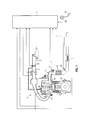
- FIG. 1 is a schematic configuration drawing of the purification apparatus of an exhaust gas of an engine according to an embodiment of the present invention.
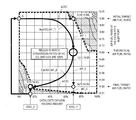
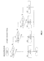
- FIG. 2 is a characteristic chart of conversion rates of NOx, HC, and CO relative to the catalyst's oxygen holding amount and the air fuel ratio at the catalyst's inlet port.
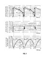
- FIG. 3 shows the timing charts each showing the change of the air fuel ratio at the catalyst's inlet port, the air fuel ratio at the catalyst's outlet port, and the catalyst's oxygen holding amount, respectively.
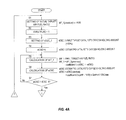
- FIG. 4A is a flow chart to explain the way how to calculate the target air fuel ratio and the estimated catalyst's oxygen holding amount.
- FIG. 4B is a flow chart to explain the way how to calculate the target air fuel ratio and the estimated catalyst's oxygen holding amount.
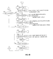
- FIG. 5 is a flow chart to explain the way how to calculate the air fuel ratio correcting coefficient.
- FIG. 1 shows a schematic configuration of the purification apparatus of the exhaust gas of the engine 1 .
- the engine 1 comprises the intake passage 2 , the throttle valve 3 , and the fuel injection valve 4 .
- the fuel injection valve 4 supplies a fuel to an intake port by injection thereof so as to give a prescribed air fuel ratio by a fuel injection signal from the engine controller 11 in accordance with an operation condition.
- the engine controller 11 receives signals that are sent from the crank angle sensor 12 , the air flow meter 13 , the accelerator sensor 14 , and the water temperature sensor 16 .
- the crank angle sensor 12 sends out a standard position signal and the unit angle signal of the crank angle.
- the air flow meter 13 sends out a signal of the intake air flow amount Qa.
- the accelerator sensor 14 sends out a signal of the depression amount (accelerator opening) of the acceleration pedal 15 .
- the water temperature sensor 16 sends out a signal of the temperature of the engine cooling water.
- the basic injection pulse width Tp 0 (ms) is calculated by the following equation from the engine rotation speed Ne that is detected by the crank angle sensor 12 and from the intake air flow amount Qa that is detected by the air flow meter 13 .
- Tp 0 K ⁇ Qa/Ne (1)
- Equation (2) the air amount that flows into a cylinder (combustion chamber) is deemed to respond in a linearly delayed fashion to the air amount that flows through the air flow meter position during transition period (during acceleration or deceleration), whereby obtaining the air fuel mixture having the theoretical air fuel ratio even to this air amount that flows into the cylinder.
- the catalysts 6 and 7 are arranged in the exhaust passage 5 of the engine 1 .
- the catalysts 6 and 7 are so-called three-way catalysts, wherein NOx, HC, and CO are purified at the maximum efficiency when the catalyst is in the atmosphere of the theoretical air fuel ratio.
- a mixture of cerium (Ce) with a precious metal (catalyst) such as platinum (Pt), palladium (Pd), and rhodium (Rh) is supported on a honeycomb structure that is coated with alumina.
- an oxygen in the exhaust gas is held (absorbed) by cerium under the condition that the air fuel ratio of the incoming exhaust gas is in the lean side of the theoretical air fuel ratio, whereby increasing the catalyst's oxygen holding amount.
- the three-way catalyst under the condition that the air fuel ratio of the incoming exhaust gas is in the rich side of the theoretical air fuel ratio, incoming components that are in the reduced state are oxidized by the oxygen held in the catalyst, whereby decreasing the catalyst's oxygen holding amount.
- the three-way catalyst has the function (oxygen holding capacity) to hold and release the oxygen in accordance with the air fuel ratio of the incoming exhaust gas.
- the front air fuel ratio sensor 17 which has a linear characteristic; and in the downstream side of the catalyst 6 is installed the rear O2 sensor 18 .
- the front air fuel ratio sensor 17 has a linear characteristic which responds to the oxygen concentration in the exhaust gas; and the rear O2 sensor 18 has a characteristic to be switched in a binary fashion at near the theoretical air fuel ratio.
- the air fuel ratio correction coefficient HOS (dimensionless quantity) is calculated based on the outputs of these sensors 17 and 18 .
- the afore-mentioned pulse width Tp which corresponds to the cylinder air amount is corrected, that is, by using the following equation the fuel injection pulse width Ti (ms) during the time of the sequential injection is calculated.
- Ti Tp ⁇ tFBYA ⁇ HOS ⁇ 2+ Ts (3)
- the fuel injection valve 4 installed in each cylinder opens by the time width which corresponds to this fuel injection pulse width Ti.
- the target equivalence ratio tFBYA of the Equation (3) is a value around 1.0 as the center thereof; and when this value is 1.0, the air fuel mixture having the theoretical air fuel ratio is obtained. On the other hand, if this value is more than 1.0, the air fuel mixture in the rich side of the theoretical air fuel ratio is obtained, whereas if this value is a positive value which is less than 1.0, the air fuel mixture in the lean side of the theoretical air fuel ratio is obtained.
- tFBYA shall be 1.0.
- the air fuel mixture having the theoretical air fuel ratio cannot be obtained thereby leading the air fuel ratio of the exhaust gas to the rich side or the lean side of the theoretical air fuel ratio; however, this is not considered here. In other words, it is considered that there is no detection error in the air flow meter 13 or variation in the flow characteristics of the fuel injection valve 4 .
- Content of the air fuel ratio correction coefficient HOS of the equation (3) is newly introduced in the present embodiment; and a detail explanation thereof will be given later.
- the conventional way used to control the air fuel ratio in the engine 1 having the catalyst 6 can be explained as follows; that is, the oxygen holding amount of the catalyst 6 is estimated, whereby the air fuel ratio of the exhaust gas is controlled so as to coincide this estimated catalyst's oxygen holding amount with a target value of the catalyst's oxygen holding amount.
- the oxygen holding amount of the catalyst 6 is called as “catalyst's oxygen holding amount”, the estimated value of the catalyst's oxygen holding amount as “estimated catalyst's oxygen holding amount”, and the target value of the catalyst's oxygen holding amount as “target catalyst's oxygen holding amount”.
- the catalyst's oxygen holding amount is expressed in terms of %, wherein the maximum catalyst's oxygen holding amount is taken as 100%, and the minimum catalyst's oxygen holding amount is taken as 0%.
- the estimated catalyst's oxygen holding amount is calculated from the difference between the theoretical air fuel ratio and the air fuel ratio at the inlet port of the catalyst 6 that is detected by the front air fuel ratio sensor 17 , the exhaust gas flow amount Qexh, and the excess or deficient oxygen concentration FO2 in the exhaust gas.
- the estimated catalyst's oxygen holding amount is reset at the minimum catalyst's oxygen holding amount (or the maximum catalyst's oxygen holding amount). That is, the estimated catalyst's oxygen holding amount is corrected.
- the estimated catalyst's oxygen holding amount is not corrected. That the estimated catalyst's oxygen holding amount is not corrected means that a discrepancy is generated between the estimated catalyst's oxygen holding amount and the actual catalyst's oxygen holding amount.
- the state that the exhaust gas cleaning performance of the catalyst 6 is low continues. For example, when the actual catalyst's oxygen holding amount becomes 0% whereby leading to the deficient state of oxygen to oxidize HC and CO in the exhaust gas, it is necessary to let the catalyst 6 take in oxygen by directing the air fuel ratio of the exhaust gas toward the lean side. At this time, unless the estimated catalyst's oxygen holding amount is 0%, the air fuel ratio of the exhaust gas cannot be directed toward the lean side so that HC and CO in the exhaust gas cannot be oxidized by the catalyst 6 .
- FIG. 2 the region in which conversion rate of NOx is 100% and the region in which conversion rates of HC and CO become 100% are interposed on a plane wherein the catalyst's oxygen holding amount is shown in a horizontal axis and the air fuel ratio (air fuel ratio in the exhaust gas) at the inlet port of the catalyst 6 is shown in a vertical axis.
- the region in which the air fuel ratio at the catalyst's inlet port is in the rich side (lower side in FIG. 2 ) of the theoretical air fuel ratio of 14.69 and the catalyst's oxygen holding amount is near to 0% is hatched.
- This hatched region in the lower left is the region in which conversion rates of HC and CO are less than 100% (namely, the region in which all of HC and CO in the exhaust gas cannot be cleaned by oxidation).
- the region in which the air fuel ratio at the catalyst's inlet port is in the lean side (upper side in FIG. 2 ) of the theoretical air fuel ratio of 14.69 and the catalyst's oxygen holding amount is near to 100% is also hatched.
- This hatched region in the upper right is the region in which conversion rate of NOx is less than 100% (namely, the region in which all of NOx in the exhaust gas cannot be cleaned by reduction). Therefore, the rest region (region enclosed by the dashed line) other than these two hatched regions in the lower left and the upper right is the region in which conversion rates of HC, CO, and NOx become 100%.
- control of the air fuel ratio shown in following (1) to (5) shall be carried out in the present embodiment.
- the changing rate of the first target air fuel ratio tAF_1 toward a richer side is determined based on the difference between the first target catalyst's oxygen holding amount tOSC_1 and the estimated catalyst's oxygen holding amount eOSC (first catalyst's oxygen holding amount).
- the estimated catalyst's oxygen holding amount eOSC (first catalyst's oxygen holding amount) that is used to calculate the first target air fuel ratio is calculated based on the difference between the theoretical air fuel ratio of 14.69 and the air fuel ratio rAF at the catalyst's inlet port that is detected by the front air fuel ratio sensor 17 .
- the changing rate of the second target air fuel ratio tAF_2 toward a richer side is determined based on the difference between this second target catalyst's oxygen holding amount tOSC_2 and the estimated catalyst's oxygen holding amount eOSC (second catalyst's oxygen holding amount).
- the estimated catalyst's oxygen holding amount eOSC (second catalyst's oxygen holding amount) that is used to calculate the second target air fuel ratio is calculated based on the difference between the theoretical air fuel ratio of 14.69 and the air fuel ratio rAF at the catalyst's inlet port that is detected by the front air fuel ratio sensor 17 .
- the final target air fuel ratio is given by the air fuel ratio obtained by subtracting the difference (0.19) between the initial target air fuel ratio of 14.88 and the theoretical air fuel ratio of 14.69 from the theoretical air fuel ratio of 14.69. That is, the changing width of the first target air fuel ratio tArF_1 changed in the lean side of the theoretical air fuel ratio of 14.69 is made to be the same as the changing width of the second target air fuel ratio tArF_2 changed in the rich side of the theoretical air fuel ratio of 14.69.
- the operation point is made to direct further toward a richer side from Point F.
- the air fuel ratio at the outlet port of the catalyst 6 is made to be judged in the rich side of the theoretical air fuel ratio of 14.69 by the output of the rear O2 sensor 18 . Therefore, the air fuel ratio directed toward a richer side from the final target air fuel ratio of 14.50 to Point H is calculated as the third air fuel ratio tAF_3.
- the third target air fuel ratio tAF_3 is made to change at a faster rate than the rate of the first target air fuel ratio tAF_1.
- the operation point is moved from Point A, to Point C, and then to Point F in the plane of the catalyst's oxygen holding amount and the air fuel ratio at the catalyst's inlet port as well as in the region in which the respective conversion rates of HC, CO, and NOx are 100%; and this cycle operation is repeated.
- the curve B is the track of the point which is determined by the estimated catalyst's oxygen holding amount eOSC and the first target air fuel ratio tAF_1.
- the curve E is the track of the point which is determined by the estimated catalyst's oxygen holding amount eOSC and the second target air fuel ratio tAF_2.
- the operation point is moved from Point F toward a richer side once, and after the air fuel ratio at the outlet port of the catalyst 6 is made to be judged in the rich side of the theoretical air fuel ratio by the output of the rear O2 sensor 18 , operation is moved back to Point A.
- the estimated catalyst's oxygen holding amount eOSC can be corrected in every cycle.
- the estimated catalyst's oxygen holding amount eOSC does not deviate largely from the actual catalyst's oxygen holding amount; and thus, continuation of the situation that the cleaning performance of the catalyst 6 as to the exhaust gas is deteriorated by the discrepancy can be avoided.
- the control method of the air fuel ratio is not limited to the case of FIG. 2 .
- the changing width of the first target air fuel ratio tArF_1 changed in the lean side of the theoretical air fuel ratio of 14.69 may be different from the changing width of the second target air fuel ratio tArF_2 changed in the rich side of the theoretical air fuel ratio of 14.69.
- the initial target air fuel ratio is not limited to 14.88, and the final target air fuel ratio is not limited to 14.50, so that they may be larger or smaller than these values.
- the initial target air fuel ratio of 14.84 may be selected.
- the maximum value of the catalyst's oxygen holding amount with which conversion rate of NOx can be kept at 100% with the initial target air fuel ratio of 14.84 becomes 75%, so that the first target catalyst's oxygen holding amount tOSC_1 may be set at 75%.
- the final target air fuel ratio of 14.54 may be selected.
- the minimum value of the catalyst's oxygen holding amount with which conversion rates of HC and CO can be kept at 100% with the final target air fuel ratio of 14.54 becomes about 15%, so that the second target catalyst's oxygen holding amount tOSC_2 may be set at 15%.
- the model to show how the air fuel ratio at the inlet port of the catalyst 6 , the air fuel ratio at the outlet port of the catalyst 6 , and the catalyst's oxygen holding amount change may be depicted in FIG. 3 .
- Point H, Point D, Point C, and Point G each corresponds to Point H, Point D, Point C, and Point G in FIG. 2 , respectively.
- the control is started at the timing of t 1 with setting the initial target air fuel ratio of 14.88.
- the first target air fuel ratio tAF_1 which becomes gradually richer from the initial target air fuel ratio of 14.88 to the theoretical air fuel ratio of 14.69 is calculated.
- the second target air fuel ratio tAF_2 which becomes gradually richer from the theoretical air fuel ratio of 14.69 to the final target air fuel ratio of 14.50 is calculated.
- the third target air fuel ratio tAF_3 is calculated as the air fuel ratio directing toward a richer side than the final target air fuel ratio of 14.50. From the timing of t 4 , the above operation is repeated.
- the air fuel ratio at the outlet port of the catalyst 6 is detected by an air fuel ratio sensor which has a linear characteristic, not by the rear O2 sensor 18 . Therefore, in the middle column of FIG. 3 , the rich judgment is made when the air fuel ratio at the outlet port of the catalyst 6 passes over the rich slice level (this is between 14.5 and 14.6) by the third target air fuel ratio tAF_3 at the timing of t 4 in the course of directing toward a richer side.
- the scenario is set so as to make the rich judgment by the output of the rear O2 sensor 18 in the course of the operation point directing toward a smaller side (richer side) than the final target air fuel ratio of 14.50; and thus, FIG.
- the first target catalyst's oxygen holding amount tOSC_1 is set at 70%
- the second target catalyst's oxygen holding amount tOSC_2 is set at 15%; namely these two target values are set.
- the estimated catalyst's oxygen holding amount eOSC is set at 0% as the initial setting at the timing of t 1
- the estimated catalyst's oxygen holding amount eOSC reaches the first target catalyst's oxygen holding amount tOSC_1 at the timing of t 2 .
- the estimated catalyst's oxygen holding amount eOSC is set at 0% again as the initial setting.
- the flow charts of FIG. 4A and FIG. 4B are for calculating the target air fuel ratio and the estimated catalyst's oxygen holding amount.
- the flow charts of FIG. 4A and FIG. 4B are to show the procedures; and these are not for execution at every constant interval (for example, in every 10 ms).
- the flow charts of FIG. 4A and FIG. 4B are based on the assumption that the situation is in the feedback control region of the air fuel ratio.
- the condition of the feedback control region of the air fuel ratio is fulfilled by activating the front air fuel ratio sensor 17 and the catalyst 6 .
- the rear O2 sensor 18 needs to be activated, too; however, because the rear O2 sensor 18 is located in the downstream side of the catalyst 6 , it is thought that the rear O2 sensor 18 is also activated at the timing when activation of the catalyst 6 is completed.
- the step S 1 to the step S 7 show the calculation parts of the target air fuel ratio (first target air fuel ratio) and the estimated catalyst's oxygen holding amount (first estimated catalyst's oxygen holding amount) from Point A to Point C of FIG. 2 .
- the initial target air fuel ratio of 14.88 is set.
- the first target air fuel ratio tAF_1 is the value which becomes gradually smaller from the initial target air fuel ratio of 14.88 to the theoretical air fuel ratio of 14.69, so that 14.88 is put in tAF_1 (previous), which is the previous value of the first target air fuel ratio.
- the first target catalyst's oxygen holding amount tOSC_1 is set at 70%. This amount of 70% is, as shown above, the maximum value of the catalyst's oxygen holding amount with which conversion rate of NOx can be kept at 100% with the initial target air fuel ratio of 14.88.
- the first target catalyst's oxygen holding amount tOSC_1 is not limited to 70%; and thus, it may be a value (prescribed value) less than 70%.
- the estimated catalyst's oxygen holding amount eOSC is set at 0%.
- the estimated catalyst's oxygen holding amount eOSC is calculated as a value for the present cycle which is obtained basically by counting to the previous value the increasing or decreasing amount of the catalyst's holding amount per the calculation cycle time.
- the estimated catalyst's oxygen holding amount eOSC is initialized at 0%. This means that the estimated catalyst's oxygen holding amount eOSC is corrected by resetting the estimated catalyst's oxygen holding amount eOSC at 0% at the timing when the output of the rear O2 sensor is judged to be rich.
- the first target air fuel ratio tAF_1 is calculated by the following equation.
- tAF _1 tAF _1(previous) ⁇ coefficient 1 ⁇ ( tOSC _1 ⁇ eOSC ) (4)
- the air fuel ratio directing toward a richer side from the initial target air fuel ratio of 14.88 to the theoretical air fuel ratio of 14.69 so as to coincide the estimated catalyst's oxygen holding amount eOSC with the first target catalyst's oxygen holding amount tOSC_1 is calculated as the first target air fuel ratio tAF_1.
- tAF_1 (previous) 14.88
- tOSC_1 70%
- eOSC 0%
- the first target air fuel ratio tAF_1 in the left-hand side of the equation (5) becomes smaller than the initial target air fuel ratio of 14.88 by the second member of the right-hand side of the equation (5).
- the air fuel ratio at the catalyst's inlet port is in the lean side of the theoretical air fuel ratio, so that the air fuel ratio rAF at the catalyst's inlet port that is detected by the front air fuel ratio sensor 17 is larger than the theoretical air fuel ratio of 14.69; and thus, the second member of the right-hand side of the equation (6) becomes plus.
- the second member of the right-hand side of the equation (6) is the value, in which a value obtained by multiplying the difference between the air fuel ratio rAF and the theoretical air fuel ratio of 14.69 by the flow amount of the exhaust gas Qexh and by the calculation cycle time t thereby converting to the oxygen amount (g), followed by dividing this value by the maximum catalyst's oxygen holding amount (g), that is, this is the increased amount of the catalyst's oxygen holding amount % per the calculation cycle time.
- the value obtained by adding this increased amount of the catalyst's oxygen holding amount % per the calculation cycle time is the estimated catalyst's oxygen holding amount eOSC.
- the flow amount of the exhaust gas Qexh in the equation (6) may be detected, but Qexh may be substituted by the intake air flow amount Qa that is detected by the air flow meter 13 . The same is applied to the later-mentioned equation (10).
- the operation proceeds to the step S 8 of FIG. 4B from the step S 7 .
- the step S 8 to the step S 14 show the calculation parts of the target air fuel ratio (second target air fuel ratio) and the estimated catalyst's oxygen holding amount (second estimated catalyst's oxygen holding amount) from Point C to Point F in FIG. 2 .
- the second target catalyst's oxygen holding amount tOSC_2 is set at 15%. This amount of 15% is, as shown above, the minimum value of the catalyst's oxygen holding amount with which conversion rates of HC and CO can be kept at 100% with the final target air fuel ratio of 14.50.
- the second target catalyst's oxygen holding amount tOSC_2 is not limited to 15%; and thus, it may be a value (prescribed value) more than 15%.
- the second target air fuel ratio tAF_2 is calculated by the following equation.
- tAF _2 tAF _2(previous) ⁇ coefficient 3 ⁇ ( eOSC ⁇ tOSC _2) (8)
- the air fuel ratio directing toward a richer side from the theoretical air fuel ratio of 14.69 to the final target air fuel ratio of 14.50 so as to coincide the estimated catalyst's oxygen holding amount eOSC with the second target catalyst's oxygen holding amount tSC_2 is calculated as the second target air fuel ratio tAF_2.
- eOSC 70%
- tOSC_2 15%
- the second target air fuel ratio tAF_2 in the left-hand side of the equation (9) becomes smaller than the previous value by the second member of the right-hand side of the equation (9).
- the estimated catalyst's oxygen holding amount eOSC (second estimated catalyst's oxygen holding amount) is calculated by the afore-mentioned equation (6).
- eOSC eOSC (previous)+coefficient 2 ⁇ ( rAF ⁇ 14.69) ⁇ Qexh ⁇ t/OSC max (10)
- the air fuel ratio at the catalyst's inlet port is in the rich side of the theoretical air fuel ratio, so that the air fuel ratio rAF at the catalyst's inlet port that is detected by the front air fuel ratio sensor 17 is smaller than the theoretical air fuel ratio of 14.69; and thus, the second member of the right-hand side of the equation (6) becomes minus.
- the second member of the right-hand side of the equation (6) is the value, in which a value obtained by multiplying the difference between the air fuel ratio rAF and the theoretical air fuel ratio of 14.69 by the flow amount of the exhaust gas Qexh and by the calculation cycle time t thereby converting to the oxygen amount (g), followed by dividing this value by the maximum catalyst's oxygen holding amount (g), that is, this is the decreased amount (minus value) of the catalyst's oxygen holding amount % per the calculation cycle time.
- the value obtained by counting this decreased amount (minus value) of the catalyst's oxygen holding amount % per the calculation cycle time is the estimated catalyst's oxygen holding amount eOSC.
- the output of the rear O2 sensor becomes a value near to 1.0 V
- the output of the rear O2 sensor becomes a value near to 0 V. Therefore, the slice level is set at near 500 mV; and when the output of the rear O2 sensor is less than this slice level, the air fuel ratio at the outlet port of the catalyst 6 can be judged in the lean side of the theoretical air fuel ratio of 14.69. Further, when the output of the rear O2 sensor passes over the slice level thereby becoming more than this slice level, the air fuel ratio at the outlet port of the catalyst 6 can be judged in the rich side of the theoretical air fuel ratio of 14.69.
- the operation returns to the step S 10 , and then the operations of steps S 10 , S 11 , and S 12 are executed. That is, during the time when the rich judgment is not made and the estimated catalyst's oxygen holding amount eOSC is larger than the second target catalyst's oxygen holding amount tOSC_2, the operations of steps S 10 , S 11 , and S 12 are repeated.
- the operation proceeds from the step S 13 to the steps that follow the step S 15 .
- the step S 15 to the step S 18 show the calculation parts of the target air fuel ratio (third target air fuel ratio) from Point F to Point H in FIG. 2 .
- the initial value of the tAF_3 (previous) in the right-hand side of the equation (11) is the final target air fuel ratio of 14.50; and thus, the equation (11) calculates, as the third target air fuel ratio, the value which is smaller (namely, toward a richer side) than the final target air fuel ratio of 14.50 by the prescribed value per the calculation cycle time.
- the prescribed value in the right-hand side of the equation (11) is set so as to let the third target air fuel ratio tAF_3 change at a faster rate than the rates of the first target air fuel ratio tAF_1 and the second target air fuel ratio tAF_2. The reason for this is as follows.
- the operation point passes through the hatched region in the lower left of FIG. 2 .
- the hatched region in the lower left of FIG. 2 is the region in which the catalyst's purification performance in oxidation of HC and CO is deteriorated. Therefore, when the operation point passes through the region in which the purification performance of the catalyst 6 in oxidation of HC and CO is deteriorated, in order to shorten the residence time in the region in which the purification performance of the catalyst 6 in oxidation of HC and CO is deteriorated, the changing rate of the air fuel ratio is accelerated.
- step S 18 whether the air fuel ratio at the outlet port of the catalyst 6 is in the rich side or not is checked based on the output of the rear O2 sensor.
- the operation returns to the step S 16 , and then the operations of steps S 16 and S 17 are repeated.
- the third target air fuel ratio tAF_3 moves toward a richer side.
- the first cycle is judged to be completed thereby returning to the step S 1 of FIG. 4A in order to execute the second cycle.
- the flow chart of FIG. 5 is to calculate the air fuel correction coefficient HOS which is used in the afore-mentioned equation (3); and this is executed at every constant interval (for example, in every 10 ms).
- the first flag is checked (this has been already set in the step S 2 of FIG. 4A ).
- the initial target air fuel ratio of 14.88 is set; and thereafter, the first target air fuel ratio tAF_1 directing toward a smaller side (richer side) thereof by taking the initial target air fuel ratio as the initial value is calculated.
- the operation proceeds to the step S 32 , wherein the air fuel ratio correction coefficient HOS (dimensionless quantity) is calculated by dividing the theoretical air fuel ratio of 14.69 by the first target air fuel ratio tAF_1 (this has already been calculated in the step S 5 of FIG. 4A ), namely, by the following equation.
- HOS 14.69/ tAF _1 (12)
- the air fuel ratio correction coefficient HOS is a smaller value than 1.0 from the equation (12).
- the pulse width Tp which corresponds to the cylinder air amount (fuel injection amount) is corrected to be smaller by the air fuel ratio correction coefficient HOS of the equation (12), whereby the air fuel ratio of the air-fuel mixture moves toward a smaller side from the initial target air fuel ratio of 14.88 to the theoretical air fuel ratio of 14.69.
- the air fuel ratio correction coefficient HOS is a larger value than 1.0 from the equation (13).
- the pulse width Tp fuel injection amount
- the air fuel ratio correction coefficient HOS of the equation (13) whereby the air fuel ratio of the air-fuel mixture moves toward a smaller side from the theoretical air fuel ratio of 14.69 to the final target air fuel ratio of 14.50.
- the air fuel ratio correction coefficient HOS is a larger value than 1.0 from the equation (14).
- the pulse width Tp fuel injection amount
- the air fuel ratio correction coefficient HOS of the equation (14) whereby the air fuel ratio of the air-fuel mixture moves toward a further smaller side (richer side) than the final target air fuel ratio of 14.50.
- the air fuel ratio correction coefficient HOS that is calculated from FIG. 5 is used in the afore-mentioned equation (3).
- the purification apparatus of an exhaust gas of an engine in the present embodiment includes the catalyst 6 having an oxygen holding capacity with which an oxygen in the exhaust gas discharged from the engine 1 is held and released in accordance with the air fuel ratio in the exhaust gas, the front air fuel ratio sensor 17 , and the rear O2 sensor 18 .
- a value (14.88) in the lean side of the theoretical air fuel ratio of 14.69 is taken as the initial target air fuel ratio, whereby the first target air fuel ratio tAF_1 directing toward a richer side from the initial target air fuel ratio of 14.88 to the theoretical air fuel ratio of 14.69 is calculated based on the first target catalyst's oxygen holding amount tOSC_1 and the estimated catalyst's oxygen holding amount eOSC (first estimated catalyst's oxygen holding amount) (see the step S 5 of FIG. 4A ).
- a fuel supply amount to the engine 1 is corrected so as to obtain the first target air fuel ratio tAF_1 (see the steps S 31 and S 32 of FIG.
- the estimated catalyst's oxygen holding amount eOSC (first estimated catalyst's oxygen holding amount) is calculated (see the step S 6 of FIG. 4A ). Until the estimated catalyst's oxygen holding amount eOSC (first estimated catalyst's oxygen holding amount) reaches the first target catalyst's oxygen holding amount tOSC_1, calculations of the first target air fuel ratio tAF_1 and of the estimated catalyst's oxygen holding amount eOSC (first estimated catalyst's oxygen holding amount) are continued (see the steps S 7 , S 5 , and S 6 of FIG. 4A ).
- the second target air fuel ratio tAF_2 directing toward a richer side from the theoretical air fuel ratio of 14.69 to this final target air fuel ratio of 14.50 is calculated based on the second target catalyst's oxygen holding amount tOSC_2 and the estimated catalyst's oxygen holding amount eOSC (second estimated catalyst's oxygen holding amount) (see the step S 7 of FIG. 4A and the step S 10 of FIG. 4B ).
- a fuel supply amount to the engine 1 is corrected so as to obtain the second target air fuel ratio tAF_2 (see the steps S 33 and S 34 of FIG. 5 , as well as equation (13) and equation (3)).
- the estimated catalyst's oxygen holding amount eOSC first estimated catalyst's oxygen holding amount
- the estimated catalyst's oxygen holding amount eOSC second estimated catalyst's oxygen holding amount
- the estimated catalyst's oxygen holding amount eOSC is calculated based on the theoretical air fuel ratio of 14.69 and the air fuel ratio rAF that is detected by the front air fuel ratio sensor 17 (see the step S 12 of FIG. 4B ).
- the air fuel ratio is moved from the initial target air fuel ratio of 14.88 to the theoretical air fuel ratio of 14.69, and then from the theoretical air fuel ratio of 14.69 to the final target air fuel ratio of 14.50, and also the estimated catalyst's oxygen holding amount eOSC (first estimated catalyst's oxygen holding amount) directing toward the first target catalyst's oxygen holding amount tOSC_1 is calculated, and further the estimated catalyst's oxygen holding amount eOSC (second estimated catalyst's oxygen holding amount) directing toward the second target catalyst's oxygen holding amount tOSC_2 is calculated; and thus, the air fuel ratio can be controlled more surely in the region in which the purification performance of the catalyst 6 as to the exhaust gas is not deteriorated as compared with the case that the target air fuel ratio is calculated
- the first target catalyst's oxygen holding amount tOSC_1 is set at the catalyst's oxygen holding amount with which conversion rate of NOx becomes a prescribed value at the initial target air fuel ratio of 14.88; and thus, the operation can be done in the region in which conversion rate of NOx is in the prescribed value.
- the above-mentioned prescribed value is 100%; and thus, the operation in the region in which conversion rate of NOx is less than 100% (hatched region in the upper right of FIG. 2 ) can be avoided without fail.
- the length of the control cycle, in which the operation is done from the lean air fuel ratio, to the theoretical air fuel ratio, and then to the rich air fuel ratio can be made longer as compared with the case in which the first target catalyst's oxygen holding amount tOSC_1 is set at a value less than 70%.
- the second target catalyst's oxygen holding amount tOSC_2 is set at the catalyst's oxygen holding amount with which conversion rates of HC and CO may become the prescribed value at the final target air fuel ratio of 14.50 (air fuel ratio obtained by subtracting the difference between the initial target air fuel ratio of 14.88 and the theoretical air fuel ratio of 14.69 from the theoretical air fuel ratio of 14.69); and thus, the operation can be done in the region in which conversion rates of HC and CO are in the prescribed value.
- the operation can be done in the region in which conversion rates of HC and CO are 100%.
- the second target catalyst's oxygen holding amount tOSC_2 is 15% (minimum value with which conversion rates of HC and CO can be kept at 100%); and thus, the length of the control cycle, in which the operation is done from the lean air fuel ratio, to the theoretical air fuel ratio, and then to the rich air fuel ratio, can be made longer as compared with the case in which the second target catalyst's oxygen holding amount tOSC_2 is set at a value more than 15%.
- the estimated catalyst's oxygen holding amount eOSC (second estimated catalyst's oxygen holding amount) reaches the second target catalyst's oxygen holding amount tOSC_2
- the third target air fuel ratio tAF_3directing toward a richer side at a prescribed changing rate is calculated (see the steps S 13 and S 16 of FIG. 4B ), so that the judgment that the air fuel ratio at the outlet port of the catalyst 6 is in the rich side is made without fail by means of the rear O2 sensor 18 ; and thus, the estimated catalyst's oxygen holding amount eOSC can be corrected regularly.
- the air fuel ratio at the inlet port of the catalyst 6 is the final target air fuel ratio of 14.50.
- the region in the rich side of this final target air fuel ratio of 14.50 is the region in which the purification performance of the catalyst 6 in oxidation of HC and CO is deteriorated.
- the third target air fuel ratio tAF_3 is made to change at a faster rate than the rates of the first target air fuel ratio tAF_1 and the second target air fuel ratio tAF_2; and thus, the residence time in the region in which the purification performance of the catalyst 6 in oxidation of HC and CO is deteriorated can be shortened.
Abstract
Description
Tp0=K×Qa/Ne (1)
-
- Here, K: constant value
Tp=Tp0×Fload+Tp(previous)×(1−Fload) (2)
-
- Here, Tp (previous): previous value of Tp
- Fload: weighted average coefficient
- Here, Tp (previous): previous value of Tp
Ti=Tp×tFBYA×HOS×2+Ts (3)
-
- Here,
- tFBYA: target equivalence ratio (dimensionless quantity)
- HOS: air fuel ratio correction coefficient
- Ts: ineffective injection pulse width (ms)
- Here,
tAF_1=tAF_1(previous)−coefficient 1×(tOSC_1−eOSC) (4)
-
- tAF_1 (previous): previous value of tAF_1
- tOSC_1: first target catalyst's oxygen holding amount
- coefficient 1: coefficient (positive number) with which the catalyst's oxygen holding amount is converted to the air fuel ratio
tAF_1=14.88−coefficient 1×70% (5)
eOSC=eOSC(previous)+
-
- eOSC (previous): previous value of eOSC
- 14.69: theoretical air fuel ratio
- rAF: air fuel ratio detected by the front air
fuel ratio sensor 17 - Qexh: flow amount of the exhaust gas (cc/s)
- t: calculation cycle time (s)
- OSCmax: maximum catalyst's oxygen holding amount (g)
- coefficient 2: coefficient (positive number) with which the air fuel ratio is converted to the oxygen concentration (g/cc)
eOSC=
tAF_2=tAF_2(previous)−coefficient 3×(eOSC−tOSC_2) (8)
-
- tAF_2 (previous): previous value of tAF_2
- tOSC_2: second target catalyst's oxygen holding amount
- coefficient 3: coefficient (positive number) with which the catalyst's oxygen holding amount is converted to the air fuel ratio
tAF_2=14.69−coefficient 3×(70−15)% (9)
eOSC=eOSC(previous)+
eOSC=70−coefficient 2×(rAF−14.69)×Qexh×t/OSCmax (10)
tAF_3=tAF_3(previous)−prescribed value (11)
-
- tAF_3 (previous): previous value of tAF_3
- prescribed value: constant value (positive number)
HOS=14.69/tAF_1 (12)
HOS=14.69/tAF_2 (13)
HOS=14.69/tAF_3 (14)
Claims (11)
Applications Claiming Priority (3)
| Application Number | Priority Date | Filing Date | Title |
|---|---|---|---|
| JP2012142142 | 2012-06-25 | ||
| JP2012-142142 | 2012-06-25 | ||
| PCT/JP2013/062392 WO2014002604A1 (en) | 2012-06-25 | 2013-04-26 | Exhaust gas purification device for engine and exhaust gas purification method |
Publications (2)
| Publication Number | Publication Date |
|---|---|
| US20150204260A1 US20150204260A1 (en) | 2015-07-23 |
| US9334822B2 true US9334822B2 (en) | 2016-05-10 |
Family
ID=49782778
Family Applications (1)
| Application Number | Title | Priority Date | Filing Date |
|---|---|---|---|
| US14/411,006 Active US9334822B2 (en) | 2012-06-25 | 2013-04-26 | Purification apparatus of engine exhaust gas and method for purification of exhaust gas |
Country Status (5)
| Country | Link |
|---|---|
| US (1) | US9334822B2 (en) |
| EP (1) | EP2873824B1 (en) |
| JP (1) | JP5930031B2 (en) |
| CN (1) | CN104302883B (en) |
| WO (1) | WO2014002604A1 (en) |
Cited By (1)
| Publication number | Priority date | Publication date | Assignee | Title |
|---|---|---|---|---|
| US10603634B1 (en) | 2018-10-17 | 2020-03-31 | Denso International America, Inc. | Emission control system |
Families Citing this family (5)
| Publication number | Priority date | Publication date | Assignee | Title |
|---|---|---|---|---|
| JP6337819B2 (en) * | 2015-03-30 | 2018-06-06 | トヨタ自動車株式会社 | Internal combustion engine |
| US10323594B2 (en) * | 2016-06-17 | 2019-06-18 | Ford Global Technologies, Llc | Methods and systems for treating vehicle emissions |
| JP6537148B2 (en) * | 2017-08-04 | 2019-07-03 | 株式会社Subaru | Catalyst abnormality diagnosis device and catalyst abnormality diagnosis method |
| FR3101110B1 (en) * | 2019-09-19 | 2022-03-04 | Renault Sas | METHOD FOR ADJUSTING THE RICHNESS OF AN INTERNAL COMBUSTION ENGINE WITH CONTROL IGNITION |
| CN112664342B (en) * | 2020-12-29 | 2022-09-13 | 东风汽车集团有限公司 | Three-way catalyst control method and system |
Citations (15)
| Publication number | Priority date | Publication date | Assignee | Title |
|---|---|---|---|---|
| JP2000320375A (en) | 1999-05-11 | 2000-11-21 | Unisia Jecs Corp | Oxygen storage quantity control device for three-way catalyst |
| US20010045089A1 (en) * | 2000-02-23 | 2001-11-29 | Hideaki Kobayashi | Engine air-fuel ratio controller |
| US20020040577A1 (en) * | 2000-10-06 | 2002-04-11 | Toyota Jidosha Kabushiki Kaisha | Air-fuel ratio control apparatus of internal combustion engine |
| US20020157379A1 (en) | 2000-02-16 | 2002-10-31 | Masatomo Kakuyama | Exhaust emission control for engine |
| US20020157380A1 (en) * | 2000-02-24 | 2002-10-31 | Masatomo Kakuyama | Engine exhaust purification device |
| US20020194840A1 (en) * | 2000-06-26 | 2002-12-26 | Toyota Jidosha Kabushiki Kaisha | Air-fuel ratio control apparatus of internal combustion engine |
| US20030019485A1 (en) * | 2001-07-27 | 2003-01-30 | Nissan Motor Co., Ltd. | Air/fuel ratio controller for internal combustion engine |
| JP2003065038A (en) | 2001-08-22 | 2003-03-05 | Toyota Motor Corp | Exhaust emission control device for internal combustion engine |
| US20030159434A1 (en) * | 2002-02-25 | 2003-08-28 | Denso Corporation | Emission control apparatus for engine |
| JP2004116295A (en) | 2002-09-24 | 2004-04-15 | Hitachi Unisia Automotive Ltd | Exhaust emission control device of internal combustion engine |
| JP2005127259A (en) | 2003-10-24 | 2005-05-19 | Hitachi Ltd | Control device for engine |
| US20100192543A1 (en) | 2007-11-21 | 2010-08-05 | Toyota Jidosha Kabushiki Kaisha | Control apparatus for internal combustion engine |
| WO2011048707A1 (en) * | 2009-10-23 | 2011-04-28 | トヨタ自動車株式会社 | Air/fuel ratio control device for internal-combustion engine |
| US20110179774A1 (en) * | 2010-01-22 | 2011-07-28 | Hitachi Automotive Systems, Ltd. | Control Diagnostic Apparatus for Internal Combustion Engine |
| US20130340410A1 (en) * | 2011-03-10 | 2013-12-26 | Toyota Jidosha Kabushiki Kaisha | Control apparatus for an internal combustion engine |
Family Cites Families (2)
| Publication number | Priority date | Publication date | Assignee | Title |
|---|---|---|---|---|
| JP2002349325A (en) * | 2001-03-19 | 2002-12-04 | Unisia Jecs Corp | Air-fuel ratio control device for internal combustion engine |
| WO2011024593A1 (en) * | 2009-08-26 | 2011-03-03 | 日産自動車株式会社 | Exhaust gas purifying device for internal combustion engine and method for determining nox purifying catalyst deterioration |
-
2013
- 2013-04-26 WO PCT/JP2013/062392 patent/WO2014002604A1/en active Application Filing
- 2013-04-26 CN CN201380025809.3A patent/CN104302883B/en active Active
- 2013-04-26 US US14/411,006 patent/US9334822B2/en active Active
- 2013-04-26 JP JP2014522469A patent/JP5930031B2/en active Active
- 2013-04-26 EP EP13809655.7A patent/EP2873824B1/en active Active
Patent Citations (18)
| Publication number | Priority date | Publication date | Assignee | Title |
|---|---|---|---|---|
| JP2000320375A (en) | 1999-05-11 | 2000-11-21 | Unisia Jecs Corp | Oxygen storage quantity control device for three-way catalyst |
| US20020157379A1 (en) | 2000-02-16 | 2002-10-31 | Masatomo Kakuyama | Exhaust emission control for engine |
| US20010045089A1 (en) * | 2000-02-23 | 2001-11-29 | Hideaki Kobayashi | Engine air-fuel ratio controller |
| US20020157380A1 (en) * | 2000-02-24 | 2002-10-31 | Masatomo Kakuyama | Engine exhaust purification device |
| US20020194840A1 (en) * | 2000-06-26 | 2002-12-26 | Toyota Jidosha Kabushiki Kaisha | Air-fuel ratio control apparatus of internal combustion engine |
| US20020040577A1 (en) * | 2000-10-06 | 2002-04-11 | Toyota Jidosha Kabushiki Kaisha | Air-fuel ratio control apparatus of internal combustion engine |
| US20030019485A1 (en) * | 2001-07-27 | 2003-01-30 | Nissan Motor Co., Ltd. | Air/fuel ratio controller for internal combustion engine |
| JP2003065038A (en) | 2001-08-22 | 2003-03-05 | Toyota Motor Corp | Exhaust emission control device for internal combustion engine |
| US20030159434A1 (en) * | 2002-02-25 | 2003-08-28 | Denso Corporation | Emission control apparatus for engine |
| JP2004116295A (en) | 2002-09-24 | 2004-04-15 | Hitachi Unisia Automotive Ltd | Exhaust emission control device of internal combustion engine |
| JP2005127259A (en) | 2003-10-24 | 2005-05-19 | Hitachi Ltd | Control device for engine |
| US20100192543A1 (en) | 2007-11-21 | 2010-08-05 | Toyota Jidosha Kabushiki Kaisha | Control apparatus for internal combustion engine |
| CN101868607A (en) | 2007-11-21 | 2010-10-20 | 丰田自动车株式会社 | Control apparatus for internal combustion engine |
| US8464522B2 (en) | 2007-11-21 | 2013-06-18 | Toyota Jidosha Kabushiki Kaisha | Control apparatus for internal combustion engine |
| WO2011048707A1 (en) * | 2009-10-23 | 2011-04-28 | トヨタ自動車株式会社 | Air/fuel ratio control device for internal-combustion engine |
| US20120227385A1 (en) * | 2009-10-23 | 2012-09-13 | Toyota Jidosha Kabushiki Kaisha | Air/fuel ratio control device for internal-combustion engine |
| US20110179774A1 (en) * | 2010-01-22 | 2011-07-28 | Hitachi Automotive Systems, Ltd. | Control Diagnostic Apparatus for Internal Combustion Engine |
| US20130340410A1 (en) * | 2011-03-10 | 2013-12-26 | Toyota Jidosha Kabushiki Kaisha | Control apparatus for an internal combustion engine |
Cited By (1)
| Publication number | Priority date | Publication date | Assignee | Title |
|---|---|---|---|---|
| US10603634B1 (en) | 2018-10-17 | 2020-03-31 | Denso International America, Inc. | Emission control system |
Also Published As
| Publication number | Publication date |
|---|---|
| CN104302883B (en) | 2016-02-03 |
| EP2873824B1 (en) | 2016-08-03 |
| WO2014002604A1 (en) | 2014-01-03 |
| EP2873824A1 (en) | 2015-05-20 |
| JPWO2014002604A1 (en) | 2016-05-30 |
| EP2873824A4 (en) | 2015-09-30 |
| CN104302883A (en) | 2015-01-21 |
| US20150204260A1 (en) | 2015-07-23 |
| JP5930031B2 (en) | 2016-06-08 |
Similar Documents
| Publication | Publication Date | Title |
|---|---|---|
| US9334822B2 (en) | Purification apparatus of engine exhaust gas and method for purification of exhaust gas | |
| US8001765B2 (en) | System operable to control exhaust gas emission of engine | |
| US9188072B2 (en) | Air-fuel ratio control apparatus for an internal combustion engine | |
| US9500110B2 (en) | Exhaust purifying apparatus for internal combustion engine | |
| US10267255B2 (en) | Control system of internal combustion engine | |
| JP2008303742A (en) | Device for diagnosing deterioration of catalyst | |
| US10774767B2 (en) | Catalyst diagnosis device | |
| US10837386B2 (en) | Exhaust purification system of internal combustion engine | |
| EP3266999B1 (en) | Exhaust purification system and catalyst regeneration method | |
| US10392985B2 (en) | Exhaust purification system | |
| KR102517209B1 (en) | Method and control unit for operating a particle filter | |
| EP3267002A1 (en) | Internal combustion engine control device | |
| US20180112573A1 (en) | Exhaust purification system, and control method for exhaust purification system | |
| JP5618092B2 (en) | Failure determination device for air-fuel ratio detection device | |
| CN106574565B (en) | The control system of internal combustion engine | |
| EP3192988B1 (en) | Exhaust purification system and control method of the same | |
| JP2013241867A (en) | Controller for internal combustion engine | |
| US7415818B2 (en) | Control device of internal combustion engine | |
| JP6657633B2 (en) | Control device for internal combustion engine, internal combustion engine, and control method for internal combustion engine | |
| JP5324295B2 (en) | Exhaust gas purification system for internal combustion engine | |
| JP2010071217A (en) | Exhaust emission control device for engine | |
| JP2010249113A (en) | Exhaust emission control system of internal combustion engine |
Legal Events
| Date | Code | Title | Description |
|---|---|---|---|
| AS | Assignment |
Owner name: NISSAN MOTOR CO., LTD., JAPAN Free format text: ASSIGNMENT OF ASSIGNORS INTEREST;ASSIGNORS:SHIMOJO, SHIGEMASA;TANI, MASAYUKI;REEL/FRAME:034591/0760 Effective date: 20141021 |
|
| STCF | Information on status: patent grant |
Free format text: PATENTED CASE |
|
| MAFP | Maintenance fee payment |
Free format text: PAYMENT OF MAINTENANCE FEE, 4TH YEAR, LARGE ENTITY (ORIGINAL EVENT CODE: M1551); ENTITY STATUS OF PATENT OWNER: LARGE ENTITY Year of fee payment: 4 |
|
| MAFP | Maintenance fee payment |
Free format text: PAYMENT OF MAINTENANCE FEE, 8TH YEAR, LARGE ENTITY (ORIGINAL EVENT CODE: M1552); ENTITY STATUS OF PATENT OWNER: LARGE ENTITY Year of fee payment: 8 |