US933124A - Boring-machine. - Google Patents
Boring-machine. Download PDFInfo
- Publication number
- US933124A US933124A US41255008A US1908412550A US933124A US 933124 A US933124 A US 933124A US 41255008 A US41255008 A US 41255008A US 1908412550 A US1908412550 A US 1908412550A US 933124 A US933124 A US 933124A
- Authority
- US
- United States
- Prior art keywords
- crane
- boring
- wheel
- machine
- chuck
- Prior art date
- Legal status (The legal status is an assumption and is not a legal conclusion. Google has not performed a legal analysis and makes no representation as to the accuracy of the status listed.)
- Expired - Lifetime
Links
- 230000007246 mechanism Effects 0.000 description 6
- 238000004804 winding Methods 0.000 description 4
- 241000252073 Anguilliformes Species 0.000 description 1
- 230000009471 action Effects 0.000 description 1
- 230000032683 aging Effects 0.000 description 1
- 230000008878 coupling Effects 0.000 description 1
- 238000010168 coupling process Methods 0.000 description 1
- 238000005859 coupling reaction Methods 0.000 description 1
- 238000000034 method Methods 0.000 description 1
- 230000004048 modification Effects 0.000 description 1
- 238000012986 modification Methods 0.000 description 1
- 230000007935 neutral effect Effects 0.000 description 1
- 230000008569 process Effects 0.000 description 1
- 241000894007 species Species 0.000 description 1
Images
Classifications
-
- B—PERFORMING OPERATIONS; TRANSPORTING
- B23—MACHINE TOOLS; METAL-WORKING NOT OTHERWISE PROVIDED FOR
- B23B—TURNING; BORING
- B23B5/00—Turning-machines or devices specially adapted for particular work; Accessories specially adapted therefor
- B23B5/28—Turning-machines or devices specially adapted for particular work; Accessories specially adapted therefor for turning wheels or wheel sets or cranks thereon, i.e. wheel lathes
-
- Y—GENERAL TAGGING OF NEW TECHNOLOGICAL DEVELOPMENTS; GENERAL TAGGING OF CROSS-SECTIONAL TECHNOLOGIES SPANNING OVER SEVERAL SECTIONS OF THE IPC; TECHNICAL SUBJECTS COVERED BY FORMER USPC CROSS-REFERENCE ART COLLECTIONS [XRACs] AND DIGESTS
- Y10—TECHNICAL SUBJECTS COVERED BY FORMER USPC
- Y10T—TECHNICAL SUBJECTS COVERED BY FORMER US CLASSIFICATION
- Y10T82/00—Turning
- Y10T82/18—Lathe for wheel or axle
Definitions
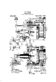
- FIG. 1 is a front elevation of a machine exemplifying my invention: Fig. 2 a side elevation of the same: Fig. 3 a plan of the same: Fig. 4 a rear elevation at a side portion of the body: and Fig. 5 a rear elevation of one of the reversing clutch devices.
- Fig. .3 is upon a reduced scale and Fig. 5 upon an enlarged scaleas compared with the other figures.
- the cross-shaft 10 will turn idly and the winding barrels will be at rest but locked by their worm gearing.
- the winding barrel of the given crane Will be drivenin the. hoisting direction, and by adjusting the same handle to an opposite position, the windingbarrel will be turnedin the lowering direction.
- Either crane maytherefore raise or lower its load by power and hold that load in any desired position.
- By appropriately manipulating both of the handles -both cranes may simultaneously lower their loads or simultaneously hoist their loads, or one crane may be hoisting its load whilethe other one is lowering its'load.
- a boring machine comprising, a body,
- a tool-bar mounted in the body and fitted for sli motion in the line of the axis of the chuc a first jib crane havpivoted on avertical axis at one side of t e chuck, a second jib crane having-its mast pivoted'on a vertical axis at the opposite side of the chuck, hoisting and lowering mechanism at each of said cranes, a power device for the actuation of sald hoisting and lowering mechanism, and coupling devices for connecting said power device with the hoisting and lowering mechanism of the two cranes alternatively or simultaneously, combined substantially as set forth.
- a boring machine comprising, a body, a chuck mounted thereon for rotation on a vertical axis, a tool-bar mounted in the body and'fitted for sliding motion in the line of the axis of the chuck, a first jib crane having its mast vertically pivoted on a vertical axis at one side of the chuck, a second jib crane having its mast pivoted on a vertical axis at the opposite side of the chuck, -hoisting and lowerlng mechanism at each of said cranes, a ower device for the actuation of said hoisting and lowering mechanism, and con ling devices for connecting said power device with the hoisting and lowering mechanism of the two cranes and adapted to hoist a load on one crane while lowering a load on the (Ethel? crane, combined substantially as set ort WILLARD T. SEARS.
Landscapes
- Engineering & Computer Science (AREA)
- Mechanical Engineering (AREA)
- Earth Drilling (AREA)
Description
W. T. SEARS.
BORING MACHINE.
APPLIOATION FILED umzs, 190s.
Patented Sept. 7, 1909.
W Mme-5m Inventor WW Lu e;
Attorney WILLARD '1. SEARS, 0F PHILADELPHIA, PENNSYIIVANIA, ASSIGNOR Tb NILES-BEMENT- POND COMPANY, OF JERSEY CITY, NEW JERSEY.
BORING-MACHINE.
Specification of Letters Patent.
Patented Sept. 7, 1909.
Application filed January 25, 1908. Serial No. 412,550.
To all whom it may concern:
Be it known that I, WILLARD T. SEARs, a citizen of the United States, residing at Philadelphia, Philadelphia county, Pennsylvania, have invented certain new and useful Improvements in Boring-Machines, of which the following is a specification.
This invention, pertaining to improvements in boring machines devised with special reference to the expeditious boring of car wheels, will be readily understood from the following description taken in connection with the accompanying drawing in which Figure 1 is a front elevation of a machine exemplifying my invention: Fig. 2 a side elevation of the same: Fig. 3 a plan of the same: Fig. 4 a rear elevation at a side portion of the body: and Fig. 5 a rear elevation of one of the reversing clutch devices. Fig. .3 is upon a reduced scale and Fig. 5 upon an enlarged scaleas compared with the other figures.
In the drawing :1, indicates the body of a car wheel boring machine of well known type: 2, the rotary chuck of the machine,
v mounted to turn on a vertical axis: 3, the
driving shaft: 4, the tool spindle mounted for vertical feeding motion in the body and having its axis in line with the axis of the chuck, all of the parts thus far considered being as usual in machines of this class and subject to the usual modifications: 5, a jib crane having its mast pivoted in brackets projecting from one side of the body of the machine, its jib being adapted to swing from a point well to one side of the machine to a point well within the margin of the chuck: 6, a crane similarly mounted upon the other side of the machine: 7, a worm-gear mounted in the lower bracket of each crane, each worm-wheel carryin a winding barrel: 8,.a hoisting chain, one for each crane, the chain passing from its winding barrel up the mast of the crane and over suitable sheaves and down from the jib sheave, the outer extremity of the chain being provided with the usual toggle to engage the bore of the car wheel to be handled by the crane: 9, a vertical shaft journaled in brackets carried by the body of the machine, one shaft to the rear of each crane, each of these shafts havin a worm en aging its appropriate one of the worm w eels: 10, a crossshaft journaled in the body of the machine near the upper ends of the worm-shafts: 11, a driving pulley fast on this cross-shaft: 12, bevel gears, one on each outer end of the cross-shaft: 13, a pair of bevel gears, one pair for each worm-shaft, these bevel gears engaging the bevel gears 12 of the cross-' shaft and being mounted loosely on their worm shafts, each of these bevel gears being provided with a clutch hub: 14, sliding clutches, one being mounted on each of the worm shafts and arranged tolook its shaft alternatively to either of the bevel gears 13 with which it cooperates: 15, a clutch-rod sliding in the upper end of each of the worm shafts and servingas means for shifting the sliding clutches: and 16, handles for operating these clutch-rods.
W'ith the sliding clutches 14 in neutral position, the cross-shaft 10 will turn idly and the winding barrels will be at rest but locked by their worm gearing. By properly adjusting one of the handles 16 the winding barrel of the given crane Will be drivenin the. hoisting direction, and by adjusting the same handle to an opposite position, the windingbarrel will be turnedin the lowering direction. Either crane maytherefore raise or lower its load by power and hold that load in any desired position. By appropriately manipulating both of the handles, -both cranes may simultaneously lower their loads or simultaneously hoist their loads, or one crane may be hoisting its load whilethe other one is lowering its'load.
In practice, while the machine is boring one wheel one of the cranes will be connected with a new wheel and hoist. that wheel to upper position, while the other crane is swung inward ready to deal with the wheel being bored. As soon as the boring of the wheel is completed, and the chuck released, the empty crane is engaged with it and the crane and bored wheel are swung aside, the other crane being immediately swung inward so as to deliver its Wheel upon the chuck, the boring of this new wheel being begun as soon as the crane can be released from it and the chuck tightened. lVhile the boring of the new wheel is in progress, the old bored wheel' may be lowered and disposed of and either of the cranes may receive and hoist a new wheel load for a repetition of the process. hen it is considered that in the rapid boring of a car wheel the handling of the work requires about as much time as the boring,
- ing is done.
a preciation will be given to'the possibilities oi the im roved mac ine which requires no extended-hoisting or lowering to be done while the machine waiting to receive or discharge a wheel.
Again, as representing perhaps the preferable practice, during the boring of a wheel ofie'ofthe cranes may be connected with the new wheel on the floor at the side of the machine and the other crane be swung inward ready to deal with the wheel being bored. When the wheel is completely bored and released from the chuck then the empty crane ma be en aged with it and swung outward with its w eel, whereupon both cranes may be set in motion, one crane lowering the old wheel while the other crane hoists the new immaterial, the chain and winder type illustrated bein merely exemplifyin ,and the same remar s a ply to the speci c mechanismillustrated or controlling the hoisting and lowering action of the cranes- .1 have simply explained the principle of. my machine and the best mode in which I'have contemplated applying that principle. .I claim 1. A boring machine comprising, a body,
ing its mast vertically a chuck. mounted thereon for rotation on a vertical axis, a tool-bar mounted in the body and fitted for sli motion in the line of the axis of the chuc a first jib crane havpivoted on avertical axis at one side of t e chuck, a second jib crane having-its mast pivoted'on a vertical axis at the opposite side of the chuck, hoisting and lowering mechanism at each of said cranes, a power device for the actuation of sald hoisting and lowering mechanism, and coupling devices for connecting said power device with the hoisting and lowering mechanism of the two cranes alternatively or simultaneously, combined substantially as set forth.
2. A boring machine comprising, a body, a chuck mounted thereon for rotation on a vertical axis, a tool-bar mounted in the body and'fitted for sliding motion in the line of the axis of the chuck, a first jib crane having its mast vertically pivoted on a vertical axis at one side of the chuck, a second jib crane having its mast pivoted on a vertical axis at the opposite side of the chuck, -hoisting and lowerlng mechanism at each of said cranes, a ower device for the actuation of said hoisting and lowering mechanism, and con ling devices for connecting said power device with the hoisting and lowering mechanism of the two cranes and adapted to hoist a load on one crane while lowering a load on the (Ethel? crane, combined substantially as set ort WILLARD T. SEARS.
Witnesses:
HERMAN J. RUoH, It. RAYMOND PORTER.
Priority Applications (1)
| Application Number | Priority Date | Filing Date | Title |
|---|---|---|---|
| US41255008A US933124A (en) | 1908-01-25 | 1908-01-25 | Boring-machine. |
Applications Claiming Priority (1)
| Application Number | Priority Date | Filing Date | Title |
|---|---|---|---|
| US41255008A US933124A (en) | 1908-01-25 | 1908-01-25 | Boring-machine. |
Publications (1)
| Publication Number | Publication Date |
|---|---|
| US933124A true US933124A (en) | 1909-09-07 |
Family
ID=3001547
Family Applications (1)
| Application Number | Title | Priority Date | Filing Date |
|---|---|---|---|
| US41255008A Expired - Lifetime US933124A (en) | 1908-01-25 | 1908-01-25 | Boring-machine. |
Country Status (1)
| Country | Link |
|---|---|
| US (1) | US933124A (en) |
-
1908
- 1908-01-25 US US41255008A patent/US933124A/en not_active Expired - Lifetime
Similar Documents
| Publication | Publication Date | Title |
|---|---|---|
| CN108928757A (en) | A kind of lifting machine and its construction method of packaged type | |
| US2703180A (en) | Crane | |
| CN112158719A (en) | Novel crane hoisting equipment | |
| US1428887A (en) | Portable crane | |
| KR20150032406A (en) | A winch system | |
| JP6128085B2 (en) | Lifting device and auxiliary drive unit | |
| CN106006377A (en) | Driving device for crane lifting mechanism | |
| CN104326383B (en) | Crane and its moment self balancing device and method | |
| CN209396787U (en) | Lifting mechanism of bridge crane | |
| JP2018104108A (en) | crane | |
| CN105271072B (en) | A kind of sliding machine interaction of 3D buildings printer is repeatedly lifted up device | |
| CN214359810U (en) | A walking trolley for a lifting device | |
| JP2014118214A (en) | Power supply device for crane lifting unit | |
| US909804A (en) | Crane mechanism. | |
| CN220684448U (en) | Crane lifting appliance for ocean platform | |
| JP2001019350A (en) | Container crane hoisting equipment | |
| CN112935326A (en) | Elevator traction accessory machining equipment and machining process thereof | |
| CN204079192U (en) | Elevator differential gear set | |
| CN104477787A (en) | Convenient maintenance machining center | |
| CN219009684U (en) | A terminal electric telescopic container spreader | |
| US1254203A (en) | Corn-shock-loading machine. | |
| CN114852923A (en) | Handling system for building material transportation operation | |
| US1295357A (en) | Combined lifting-jack and hoist. | |
| US1506341A (en) | Motor brake for electric hoists | |
| US717994A (en) | Electric crane. |