US9321373B2 - Vehicle seats - Google Patents

Vehicle seats Download PDF

Info

Publication number
US9321373B2
US9321373B2 US14/082,731 US201314082731A US9321373B2 US 9321373 B2 US9321373 B2 US 9321373B2 US 201314082731 A US201314082731 A US 201314082731A US 9321373 B2 US9321373 B2 US 9321373B2
Authority
US
United States
Prior art keywords
air chamber
airbag
peripheral wall
cushion
chambers
Prior art date
Legal status (The legal status is an assumption and is not a legal conclusion. Google has not performed a legal analysis and makes no representation as to the accuracy of the status listed.)
Expired - Fee Related, expires
Application number
US14/082,731
Other versions
US20140167465A1 (en
Inventor
Masaru Sakata
Mitsuko HAMA
Current Assignee (The listed assignees may be inaccurate. Google has not performed a legal analysis and makes no representation or warranty as to the accuracy of the list.)
Toyota Boshoku Corp
Original Assignee
Toyota Boshoku Corp
Priority date (The priority date is an assumption and is not a legal conclusion. Google has not performed a legal analysis and makes no representation as to the accuracy of the date listed.)
Filing date
Publication date
Application filed by Toyota Boshoku Corp filed Critical Toyota Boshoku Corp
Assigned to TOYOTA BOSHOKU KABUSHIKI KAISHA reassignment TOYOTA BOSHOKU KABUSHIKI KAISHA ASSIGNMENT OF ASSIGNORS INTEREST (SEE DOCUMENT FOR DETAILS). Assignors: HAMA, MITSUKO, SAKATA, MASARU
Publication of US20140167465A1 publication Critical patent/US20140167465A1/en
Application granted granted Critical
Publication of US9321373B2 publication Critical patent/US9321373B2/en
Expired - Fee Related legal-status Critical Current
Adjusted expiration legal-status Critical

Links

Images

Classifications

    • BPERFORMING OPERATIONS; TRANSPORTING
    • B60VEHICLES IN GENERAL
    • B60NSEATS SPECIALLY ADAPTED FOR VEHICLES; VEHICLE PASSENGER ACCOMMODATION NOT OTHERWISE PROVIDED FOR
    • B60N2/00Seats specially adapted for vehicles; Arrangement or mounting of seats in vehicles
    • B60N2/02Seats specially adapted for vehicles; Arrangement or mounting of seats in vehicles the seat or part thereof being movable, e.g. adjustable
    • B60N2/0284Adjustable seat-cushion length
    • B60N2/4415
    • B60N2/4495
    • BPERFORMING OPERATIONS; TRANSPORTING
    • B60VEHICLES IN GENERAL
    • B60NSEATS SPECIALLY ADAPTED FOR VEHICLES; VEHICLE PASSENGER ACCOMMODATION NOT OTHERWISE PROVIDED FOR
    • B60N2/00Seats specially adapted for vehicles; Arrangement or mounting of seats in vehicles
    • B60N2/62Thigh-rests
    • BPERFORMING OPERATIONS; TRANSPORTING
    • B60VEHICLES IN GENERAL
    • B60NSEATS SPECIALLY ADAPTED FOR VEHICLES; VEHICLE PASSENGER ACCOMMODATION NOT OTHERWISE PROVIDED FOR
    • B60N2/00Seats specially adapted for vehicles; Arrangement or mounting of seats in vehicles
    • B60N2/90Details or parts not otherwise provided for
    • B60N2/914Hydro-pneumatic adjustments of the shape
    • BPERFORMING OPERATIONS; TRANSPORTING
    • B60VEHICLES IN GENERAL
    • B60NSEATS SPECIALLY ADAPTED FOR VEHICLES; VEHICLE PASSENGER ACCOMMODATION NOT OTHERWISE PROVIDED FOR
    • B60N2/00Seats specially adapted for vehicles; Arrangement or mounting of seats in vehicles
    • B60N2/90Details or parts not otherwise provided for
    • B60N2/995Lower-leg-rests, e.g. calf-rests

Definitions

  • FIG. 6 s a cross-sectional side view of a part of a seat cushion with an ottoman having a first and second airbags therein;
  • the support member 45 extends downward from the front edge of the main body portion 14 a of the frame portion 14 .
  • the support member 45 has a surface 45 a directed in a forward direction.
  • a lower end bent portion 47 is formed at a distal end of the support member 45 .
  • the first and second airbags 51 and 55 are inflated.
  • the air chamber 56 is situated at a recess between the air chambers 52 and 53 .
  • a peripheral wall 56 a of the air chamber 56 supports a peripheral wall 53 a of the air chamber 53 from below.
  • the peripheral wall 56 a supports a peripheral wall 52 a of the air chamber 52 from behind. Back and lower portions of the peripheral wall 56 a are supported by the surface 46 and the lower end bent portion 47 .

Landscapes

  • Engineering & Computer Science (AREA)
  • Aviation & Aerospace Engineering (AREA)
  • Transportation (AREA)
  • Mechanical Engineering (AREA)
  • Seats For Vehicles (AREA)

Abstract

Embodiments of the present invention may include a vehicle seat having a seat cushion. The seat cushion may have a cushion frame, a cushion pad arranged on the cushion frame, and an airbag provided on a front portion of the seat cushion. The airbag preferably has a lower air chamber and an upper air chamber situated above the lower air chamber. The airbag is configured such that, when the upper and lower air chambers are at least partially filled with compressed air, the seat cushion is elongated while an upper portion of a peripheral wall of the lower air chamber supports a lower portion of a peripheral wall of the upper air chamber.

Description

This application claims priority to Japanese patent application serial number 2012-276911, the contents of which are incorporated herein by reference.
BACKGROUND OF THE INVENTION
1. Field of the Invention
Embodiments of the present invention relate to vehicle seats having a seat cushion with an adjustable length.
2. Description of the Related Art
Japanese Laid-Open Patent Publication No. 2008-142120 discloses a vehicle seat having a seat cushion with an adjustable length. The seat cushion has an airbag and a cushion frame with a front frame portion. The airbag is provided on the front side of the front frame portion. The airbag is inflated by being filled with compressed air in order to elongate the seat cushion. The airbag is deflated through release of the compressed air in order to shorten the seat cushion to the former length.
In this structure, it is not easy to increase the adjustable length of the seat cushion because the airbag will droop, for example, when the airbag is inflated in a forward direction.
Therefore, there is a need in the art for a vehicle seat equipped with a seat cushion having a large adjustable length.
SUMMARY OF THE INVENTION
According to an aspect of the invention, certain embodiments of the present invention include a vehicle seat having a seat cushion. The seat cushion has a cushion frame, a cushion pad arranged on the cushion frame, and an airbag provided on a front portion of the seat cushion. The airbag has a lower air chamber and an upper air chamber situated above the lower air chamber. The airbag is configured such that, when the upper and lower air chambers are at least partially filled with compressed air, the seat cushion is elongated while an upper portion of a peripheral wall of the lower air chamber supports a lower portion of a peripheral wall of the upper air chamber.
When the seat cushion is elongated, the upper and lower air chambers are filled with compressed air. The peripheral wall of the upper air chamber expands forward to elongate the seat cushion. At this time, the upper portion of the peripheral wall of the lower air chamber supports the lower portion of the peripheral wall of the upper air chamber. Thus, the peripheral wall of the upper air chamber expands forward in a stable manner. In this way, the adjustment length of the seat cushion may increase.
In another aspect of the invention, the upper air chamber may have a front upper air chamber and a rear upper air chamber situated behind the front upper air chamber. A recess or cleavage may be formed between lower portions of respective peripheral walls of the front and rear upper air chambers. The lower air chamber may have the upper portion of the peripheral wall supporting the lower portions of the respective peripheral walls of the front and rear upper air chambers from the recess below.
Thus, by virtue of the recess, the upper portion of the peripheral wall of the lower air chamber can support the respective lower portions of the peripheral walls of the front and the rear upper air chambers in a stable manner. As a result, the front and the rear upper air chambers can inflate in a stable manner, making it possible to efficiently increase the adjustable length of the seat cushion.
In another aspect of the invention, the airbag may have a first airbag having a first air chamber and a second airbag having a second air chamber. Thus, as compared with the construction in which every air chamber is formed by a single airbag, the air chambers can be formed more easily.
In another aspect of the invention, there may be provided a structure for individually controlling the injection amount and/or the discharge amount of compressed air with respect to each air chamber.
In another aspect of the invention, the cushion frame may have the front portion and/or a support member integrally or individually located within. The support member may support a lower portion of the peripheral wall of the lower air chamber. Thus, due to the support member, the airbag is supported in a stable manner. Further, the airbag can be inflated and deflated smoothly.
BRIEF DESCRIPTION OF THE DRAWINGS
FIG. 1 is a perspective view of a part of a vehicle seat's frame and first and second airbags mounted on a front frame portion of the frame;
FIG. 2 is a cross-sectional side view of a part of a seat cushion having the first and second airbags therein;
FIG. 3 is a cross-sectional side view of the part of the seat cushion in a situation that the first and second airbags are partially inflated;
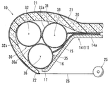
FIG. 4 is a cross-sectional side view of the part of the seat cushion in a situation that the first and second airbags are fully inflated;
FIG. 5 is a perspective view of a part of a vehicle seat frame having a front frame portion and a support member individually incorporated;
FIG. 6 s a cross-sectional side view of a part of a seat cushion with an ottoman having a first and second airbags therein; and
FIG. 7 is a cross-sectional side view of the part of the seat cushion of FIG. 6 in a situation where the first and second airbags are fully inflated.
DETAILED DESCRIPTION OF THE INVENTION
Each of the additional features and teachings disclosed above and below may be utilized separately or in conjunction with other features and teachings to provide improved vehicle seats. Representative examples of the present invention, which utilize many of these additional features and teachings both separately and in conjunction with one another, will now be described in detail with reference to the attached drawings. This detailed description is merely intended to teach a person of ordinary skill in the art further details for practicing preferred aspects of the present teachings and is not intended to limit the scope of the invention. Only the claims define the scope of the claimed invention. Therefore, combinations of features and steps disclosed in the following detailed description may not be necessary to practice the invention in the broadest sense, and are instead taught merely to particularly describe representative examples of the invention. Moreover, various features of the representative examples and the dependent claims may be combined in ways that are not specifically enumerated in order to provide additional useful configurations of the present teachings.
An embodiment of the present invention will be described with reference to FIGS. 1 to 4. As shown in FIGS. 1 and 2, a seat cushion 10 of a vehicle seat has a cushion frame 11, a cushion pad 20, and a skin member 21. The cushion pad 20 is formed of an elastic material such as urethane foam, and is arranged on the cushion frame 11. The skin member 21 covers the surface of the cushion pad 20. A front end 22 of the skin member 21 is connected to a take-up device 25. The take-up device 25 takes up and forces out the skin member 21 while maintaining it under a pre-set tension.
As shown in FIG. 1, the cushion frame 11 is of a rectangular configuration, and has side frame portions 12, a rear frame portion 13, and a front frame portion 14. Both the right and left side frame portions 12 are provided at a predetermined interval in a vehicle width direction. The rear frame portion 13 extends between rear portions of the side frame portions 12. The front frame portion 14 has a main body portion 14 a horizontally extending between front portions of the side frame portions 12, and a support member 15 extending downwardly forward from a front edge of the main body portion 14 a.
The support member 15 has an inclined surface 16 directed upwards. A lower end bent portion 17 is formed at a distal end of the support member 15.
As shown in FIGS. 1 and 2, an airbag (airbag assembly) 30 is arranged on the front frame portion 14. The airbag 30 is inflated by being filled with compressed air, and is deflated through release of the compressed air. The airbag 30 has a first airbag 31 situated on an upper side, and a second airbag 35 situated on the lower side of the first airbag 31. Distal portions 31 a and 35 a of the first and second airbags 31 and 35 are respectively fixed to an upper surface of the main body portion 14 a of the front frame portion 14. The first and second airbags 31 and 35 extend along the inclined surface 16 of the support member 15.
As shown in FIG. 2, the first airbag 31 has air chambers 32 and 33 as upper air chambers. The air chamber 32 extends in the vehicle width direction at a position corresponding to a front region of the support member 15. The air chamber 33 extends in the vehicle width direction at a position corresponding to a rear region of the support member 15. The air chambers 32 and 33 may partially communicate with each other.
The second airbag 35 has an air chamber 36 as a lower air chamber. The air chamber 36 extends in the vehicle width direction. The air chambers 32, 33, and 36 are connected to a compressor (not shown) via a selector valve. The compressor generates compressed air. The selector valve allows an individual supply of compressed air to the air chambers 32, 33, and 36.
As shown in FIG. 4, through filling of the air chambers 32, 33, and 36 with compressed air, the first airbag 31 and the second airbag 35 are inflated. The air chamber 36 is situated at a recess (or cleavage) between the air chambers 32 and 33. A peripheral wall 36 a of the air chamber 36 supports respective peripheral walls 32 a and 33 a of the air chambers 32 and 33 from below. Lower side and (rear) side portions of the peripheral wall 36 a of the air chamber 36 are supported by a lower portion of the inclined surface 16 of the support member 15 and by the lower end bent portion 17. A (rear) side portion of the peripheral wall 33 a of the air chamber 33 is supported by an upper portion of the inclined surface 16.
As shown in FIGS. 3 and 4, when the seat cushion 10 is elongated, the air chambers 32, 33, and 36 are inflated. A wire 26 of the take-up device 25 is forwardly forced out, with the tension applied to the skin member 21 being maintained at a predetermined magnitude. As a result, the seat cushion 10 is elongated forwardly in a stable manner.
The seat cushion 10 has a seat length corresponding, for example, to a region extending substantially horizontally. The front end of the seat length in FIG. 2 corresponds to the front end of the main body portion 14 a of the front frame portion 14. The front end of the seat length in FIG. 3 is situated above the support member 15. The front end of the seat length in FIG. 4 is situated forward at a front end of the support member 15.
As shown in FIGS. 3 and 4, when the seat cushion 10 is long, the upper portion of the peripheral wall 36 a of the air chamber 36 supports the lower portions of the peripheral walls 32 a and 33 a of the air chambers 32 and 33. Thus, the seat cushion 10 is elongated in a stable manner, and the adjustable length of the seat cushion 10 may increase.
As shown in FIG. 4, at the time of inflation of the airbags 31 and 35 (in particular, at the time of full inflation), a recess is formed between the lower portions of the peripheral walls 32 a and 33 a of the air chambers 32 and 33. The air chamber 36 is situated at the recess between the lower portions of the air chambers 32 and 33. The upper portion of the peripheral wall 36 a of the air chamber 36 supports the lower portions of the air chambers 32 and 33. As a result, the second airbag 35 can support the first airbag 31 in a stable manner. As a result of the inflation of the front and rear air chambers 32 and 33 of the airbag 31, the seat cushion 10 is elongated. Thus, it is possible to efficiently adjust the length of the seat cushion 10.
As shown in FIGS. 2 to 4, the airbag 30 has the first airbag 31 situated on the upper side and the second airbag 35 situated on the lower side. The first airbag 31 has the air chambers 32 and 33 longitudinally arranged with respect to each other. The second airbag 35 has the air chamber 36. Thus, the air chambers 32 and 33 situated on the upper side and the air chamber 36 situated on the lower side can be easily formed through separate formation.
The injection and discharge amounts of compressed air of the air chambers 32, 33, and 36 can be individually controlled. Thus, it is possible to elongate the seat cushion 10 in a stable manner.
As shown in FIG. 4, the lower portion of the peripheral wall 36 a of the air chamber 36 and the (rear) side wall portion thereof are supported by the lower portion of the inclined surface 16 of the support member 15 and by the lower end bent portion 17. Thus, the airbags 31 and 35 are supported in a stable manner, and can be inflated and deflated smoothly.
While the embodiments of invention have been described with reference to specific configurations, it will be apparent to those skilled in the art that many alternatives, modifications and variations may be made without departing from the scope of the present invention. Accordingly, embodiments of the present invention are intended to embrace all such alternatives, modifications and variations that may fall within the spirit and scope of the appended claims. For example, embodiments of the present invention should not be limited to the representative configurations, but may be modified, for example, as described below.
As shown in FIG. 4, the air chambers 32 and 33 may be provided in the first airbag 31, and the air chamber 36 may be provided in the second airbag 35. Alternatively, a plurality, for example more than two, of air chambers may be provided in a single airbag.
As shown in FIG. 4, the cushion frame 11 may have a front frame portion 14 and a support member 15 that are continuously integrated. Alternatively, as shown in FIG. 5, the cushion frame 11 may have a support member 115 and the front frame portion 14 individually constructed. The first and second airbags 31 and 35 may be mounted to the support member 115. The support member 115 may be mounted to the front frame portion 14. The support member 115 may be detachably attached to the front frame portion 14 by a mounting means such as a screw or a clip. As a result, the airbags 31 and 35 can be easily mounted to the cushion frame 11.
As shown in FIGS. 2 to 4, the seat cushion 10 may have the support member 15 and the air bag 30. Alternatively, as shown in FIGS. 6 and 7, the seat cushion 10 may have a support member 45 and an airbag 50. The support member 45 and airbag 50 elongate the front portion of the seat cushion 10 in a forward direction. Thus the front of the cushion 10 may be changed into an ottoman 40 for supporting the calves of a user sitting on the seat cushion 10.
As shown in FIGS. 6 and 7, the support member 45 extends downward from the front edge of the main body portion 14 a of the frame portion 14. The support member 45 has a surface 45 a directed in a forward direction. A lower end bent portion 47 is formed at a distal end of the support member 45.
As shown in FIGS. 6 and 7, an airbag (airbag assembly) 50 is situated on a front side of the support member 45. The airbag 50 has a first airbag 51 situated on a front side, and a second airbag 55 situated on a back side of the first airbag 51. Distal portions 51 a and 55 a of the first and second airbags 51 and 55 are fixed to the upper surface of the main body portion 14 a. The first airbag 51 has a front air chamber 52 and an upper air chamber 53. The air chambers 52 and 53 may partially communicate with each other. The second airbag 55 preferably has a lower air chamber 56.
As shown in FIGS. 6 and 7, through filling of the air chambers 52, 53, and 56 with compressed air, the first and second airbags 51 and 55 are inflated. The air chamber 56 is situated at a recess between the air chambers 52 and 53. A peripheral wall 56 a of the air chamber 56 supports a peripheral wall 53 a of the air chamber 53 from below. The peripheral wall 56 a supports a peripheral wall 52 a of the air chamber 52 from behind. Back and lower portions of the peripheral wall 56 a are supported by the surface 46 and the lower end bent portion 47.
As shown in FIGS. 6 and 7, when the air chambers 52, 53, and 56 are inflated, the front portion of the seat cushion 10 is elongated. The front portion extends forward such that an upper surface thereof extends forward and downward. Thus the front portion is used as the ottoman 40 for supporting the calves of the user. The take-up device 25 rolls out the wire 26. The skin member 21 moves forward and an end of the skin member 21 covers a space between an end of the cushion pad 20 and the lower end bent portion 47.
As shown in FIGS. 6 and 7, the ottoman 40 may include the air chambers 52, 53 and 56. Alternatively, the ottoman 40 may include two of the air chambers 52, 53 and 56; for example, the air chambers 53 and 56. Alternatively, the ottoman 40 may include more than three air chambers.

Claims (7)

This invention claims:
1. A vehicle seat comprising:
a wire;
a take-up device connected to the wire; and
a seat cushion including:
a cushion frame having a front portion and an upper surface;
a cushion pad arranged on the upper surface of the cushion frame; and
an airbag provided on the front portion of the cushion frame, the airbag including:
a lower air chamber having a peripheral wall with upper and lower portions; and
an upper air chamber having a peripheral wall with upper and lower portions, the upper air chamber being situated above the lower air chamber, wherein
the lower and upper air chambers are respectively attached to the upper surface of the cushion frame,
the cushion frame supports the lower portion of the peripheral wall of the lower air chamber and the upper portion of the peripheral wall of the lower air chamber supports the lower portion of the peripheral wall of the upper air chamber such that when the upper and lower chambers are at least partially filled with compressed air, the seat cushion is elongated in a stable manner, and
the wire is connected to a front end of a skin member of the seat cushion and configured such that when the air bag is at least partially filled with compressed air, the wire is forwardly forced out of the take-up device and applies tension to the skin member at a predetermined magnitude to forwardly elongate the seat cushion in the stable manner.
2. The vehicle seat of claim 1, wherein the upper air chamber further comprises:
a front upper air chamber including a peripheral wall; and
a rear upper air chamber including a peripheral wall, the rear upper air chamber being situated behind the front upper air chamber wherein
a recess is provided between lower portions of the respective peripheral walls of the front and rear upper air chambers, and
the upper portion of the peripheral wall of the lower air chamber supports the lower portions of the respective peripheral walls of the front and rear upper air chambers from the recess below.
3. The vehicle seat of claim 1, wherein the airbag further comprises:
a first airbag having a first air chamber; and
a second airbag having a second air chamber.
4. The vehicle seat of claim 1, wherein the cushion frame further comprises a support member, wherein
the support member is configured to support the lower portion of the peripheral wall of the lower air chamber.
5. The vehicle seat of claim 1, wherein the airbag is configured such that the compressed air is individually supplied to the lower and upper air chambers.
6. The vehicle seat of claim 1, the airbag further comprising:
a front air chamber including a peripheral wall, the front air chamber being situated in front of the upper and lower air chambers, wherein
a recess is provided between the respective peripheral walls of the front and upper air chambers, and
the peripheral wall of the lower air chamber supports the respective peripheral walls of the front and upper air chambers from the recess below.
7. The vehicle seat of claim 1, wherein the cushion frame further comprises a support member, the upper and lower air chambers are attached to the support member, and the support member is detachably mounted to the front portion of the cushion frame.
US14/082,731 2012-12-19 2013-11-18 Vehicle seats Expired - Fee Related US9321373B2 (en)

Applications Claiming Priority (2)

Application Number Priority Date Filing Date Title
JP2012-276911 2012-12-19
JP2012276911A JP5962490B2 (en) 2012-12-19 2012-12-19 Vehicle seat

Publications (2)

Publication Number Publication Date
US20140167465A1 US20140167465A1 (en) 2014-06-19
US9321373B2 true US9321373B2 (en) 2016-04-26

Family

ID=50878973

Family Applications (1)

Application Number Title Priority Date Filing Date
US14/082,731 Expired - Fee Related US9321373B2 (en) 2012-12-19 2013-11-18 Vehicle seats

Country Status (4)

Country Link
US (1) US9321373B2 (en)
JP (1) JP5962490B2 (en)
CN (1) CN203651544U (en)
DE (1) DE102013224197B4 (en)

Cited By (13)

* Cited by examiner, † Cited by third party
Publication number Priority date Publication date Assignee Title
US9610872B2 (en) * 2015-08-10 2017-04-04 Ford Global Technologies, Llc Thigh support providing full height auxiliary firmness for an unoccupied and unfolded, fold flat, air suspended seat
US10045623B2 (en) * 2015-02-09 2018-08-14 Faurecia Automotive Seating, Llc Variable-sized occupant support
US10246193B1 (en) * 2018-02-08 2019-04-02 B/E Aerospace, Inc. Passenger seat with articulated pneumatic seat cushion
US10449878B2 (en) * 2018-02-02 2019-10-22 GM Global Technology Operations LLC Seat trim management system for seat cushion length adjustment
US10773624B2 (en) 2017-09-28 2020-09-15 Faurecia Automotive Seating, Llc Cushion-length adjuster for vehicle seat
US11007964B2 (en) * 2018-07-31 2021-05-18 Toyoda Gosei Co., Ltd. Seat cushion airbag apparatus
US11021090B2 (en) * 2019-09-27 2021-06-01 Lear Corporation Seat assembly with leg support
US11364831B2 (en) * 2018-11-05 2022-06-21 Faurecia Autositze Gmbh Motor vehicle seat
US11554689B2 (en) 2020-08-31 2023-01-17 Deere & Company Seating arrangement
US11571998B2 (en) * 2018-10-29 2023-02-07 Volkswagen Aktiengesellschaft Vehicle seat for a motor vehicle
US11945515B2 (en) 2020-08-31 2024-04-02 Deere & Company Utility vehicle
US11964598B2 (en) 2020-08-31 2024-04-23 Deere & Company Utility vehicle
US20240253528A1 (en) * 2022-12-09 2024-08-01 Yanfeng International Seating Systems Co., Ltd. Seat for vehicle

Families Citing this family (45)

* Cited by examiner, † Cited by third party
Publication number Priority date Publication date Assignee Title
JP5966791B2 (en) * 2012-09-13 2016-08-10 トヨタ紡織株式会社 Method for manufacturing vehicle seat with side airbag
DE202013012342U1 (en) * 2012-09-20 2016-06-08 Faurecia Automotive Seating, Llc Seat cushion for a vehicle seat
US9399418B2 (en) 2013-01-24 2016-07-26 Ford Global Technologies, Llc Independent cushion extension and thigh support
US9415713B2 (en) 2013-01-24 2016-08-16 Ford Global Technologies, Llc Flexible seatback system
US9409504B2 (en) 2013-01-24 2016-08-09 Ford Global Technologies, Llc Flexible seatback system
US9016784B2 (en) * 2013-01-24 2015-04-28 Ford Global Technologies, Llc Thin seat leg support system and suspension
JP6197501B2 (en) * 2013-09-03 2017-09-20 トヨタ紡織株式会社 Cushion length variable seat
US9315131B2 (en) 2014-01-23 2016-04-19 Ford Global Technologies, Llc Suspension seat back and cushion system having an inner suspension panel
US9421894B2 (en) 2014-04-02 2016-08-23 Ford Global Technologies, Llc Vehicle seating assembly with manual independent thigh supports
EP2944510A1 (en) * 2014-05-14 2015-11-18 Lantal Textiles AG Vehicle seat with adjustable seating surface
US9789790B2 (en) 2014-10-03 2017-10-17 Ford Global Technologies, Llc Tuned flexible support member and flexible suspension features for comfort carriers
JP6468076B2 (en) 2015-05-26 2019-02-13 トヨタ紡織株式会社 Vehicle seat support device
US10046682B2 (en) 2015-08-03 2018-08-14 Ford Global Technologies, Llc Back cushion module for a vehicle seating assembly
US9994138B2 (en) * 2015-12-02 2018-06-12 Ford Global Technologies, Llc Seat with deployable plastic beam
US10035438B2 (en) 2016-02-22 2018-07-31 Ford Global Technologies, Llc Vehicle seat bottom with independently deployable devices
US9738187B1 (en) * 2016-02-22 2017-08-22 Ford Global Technologies, Llc Vehicle seat bottom with independently deployable devices
US9849817B2 (en) 2016-03-16 2017-12-26 Ford Global Technologies, Llc Composite seat structure
US10286818B2 (en) 2016-03-16 2019-05-14 Ford Global Technologies, Llc Dual suspension seating assembly
US9994135B2 (en) 2016-03-30 2018-06-12 Ford Global Technologies, Llc Independent cushion thigh support
US10220737B2 (en) 2016-04-01 2019-03-05 Ford Global Technologies, Llc Kinematic back panel
US9889773B2 (en) 2016-04-04 2018-02-13 Ford Global Technologies, Llc Anthropomorphic upper seatback
DE102016004206A1 (en) * 2016-04-06 2017-07-06 Daimler Ag Device for changing a contour of a vehicle seat and vehicle seat
US9802512B1 (en) 2016-04-12 2017-10-31 Ford Global Technologies, Llc Torsion spring bushing
CN105835732A (en) * 2016-05-16 2016-08-10 长春富维—江森自控汽车饰件系统有限公司 Automobile seat leg massage system
US9845029B1 (en) 2016-06-06 2017-12-19 Ford Global Technologies, Llc Passive conformal seat with hybrid air/liquid cells
US9834166B1 (en) 2016-06-07 2017-12-05 Ford Global Technologies, Llc Side airbag energy management system
US9849856B1 (en) 2016-06-07 2017-12-26 Ford Global Technologies, Llc Side airbag energy management system
US10166895B2 (en) 2016-06-09 2019-01-01 Ford Global Technologies, Llc Seatback comfort carrier
US10377279B2 (en) 2016-06-09 2019-08-13 Ford Global Technologies, Llc Integrated decking arm support feature
US10286824B2 (en) 2016-08-24 2019-05-14 Ford Global Technologies, Llc Spreader plate load distribution
US10279714B2 (en) 2016-08-26 2019-05-07 Ford Global Technologies, Llc Seating assembly with climate control features
US10391910B2 (en) 2016-09-02 2019-08-27 Ford Global Technologies, Llc Modular assembly cross-tube attachment tab designs and functions
US10239431B2 (en) 2016-09-02 2019-03-26 Ford Global Technologies, Llc Cross-tube attachment hook features for modular assembly and support
US10286825B2 (en) * 2016-09-08 2019-05-14 Ford Global Technologies, Llc Support assembly for a vehicle seat
US10059239B2 (en) * 2016-09-20 2018-08-28 Ford Global Technologies, Llc Air bladder with stacked cell system
US10220754B2 (en) * 2016-10-18 2019-03-05 Ford Global Technologies, Llc Inflatable member
US9914378B1 (en) 2016-12-16 2018-03-13 Ford Global Technologies, Llc Decorative and functional upper seatback closeout assembly
JP6825359B2 (en) * 2016-12-27 2021-02-03 トヨタ紡織株式会社 Vehicle seat
US10596936B2 (en) 2017-05-04 2020-03-24 Ford Global Technologies, Llc Self-retaining elastic strap for vent blower attachment to a back carrier
DE102018102596A1 (en) * 2018-02-06 2019-08-08 Adient Engineering and IP GmbH VEHICLE SEAT WITH ADJUSTABLE SIDE WALK
JP2019206240A (en) * 2018-05-29 2019-12-05 日本発條株式会社 Vehicle seat
US10765219B1 (en) * 2019-04-17 2020-09-08 Ka Group Ag Lounger having a pneumatic lounging system
US11097642B2 (en) * 2019-12-05 2021-08-24 Ford Global Technologies, Llc Vehicle seating assembly leg support with bladder
US11077817B1 (en) 2020-01-23 2021-08-03 Ford Global Technologies, Llc Airbag assembly inflatable from seat bottom
CN111791780B (en) * 2020-06-12 2023-03-24 廊坊市金色时光科技发展有限公司 Automobile seat with leg supporting function

Citations (25)

* Cited by examiner, † Cited by third party
Publication number Priority date Publication date Assignee Title
US3330598A (en) * 1966-02-14 1967-07-11 Whiteside George Harold Pneumatic seat
JPS61204553A (en) 1985-08-23 1986-09-10 Hitachi Chem Co Ltd Detecting method for combustion light of test-piece of plastic material
US4615563A (en) * 1984-11-09 1986-10-07 Tachikawa Spring Co., Ltd. Vehicle seat
US4699424A (en) * 1985-10-24 1987-10-13 Daimler-Benz Aktiengesellschaft Adjustable back support for motor vehicles
US4759543A (en) * 1986-10-27 1988-07-26 Feldman Susan M Passive exercise cushion
JPH02141233A (en) 1988-11-22 1990-05-30 Toyo Metaraijingu Kk Laminated transfer film for printed wiring board
US4965899A (en) * 1985-07-16 1990-10-30 Okamoto Industries,Inc. Air cushion for chair and chair utilizing the air cushion
US5082326A (en) * 1989-04-28 1992-01-21 Okamoto Industries, Inc. Vehicle seat with automatic adjustment mechanisms utilizing inflatable air bags
US5431112A (en) * 1994-03-31 1995-07-11 International Material Control Systems, Inc. Safety locking system for air-operated tilt tables
US5572933A (en) * 1994-03-31 1996-11-12 International Material Control Systems Inc. Safety locking system for air-operated tilt tables
US5658050A (en) * 1996-01-11 1997-08-19 Milsco Manufacturing Company Vehicle seat with inflatable bladder
US5904219A (en) * 1998-01-15 1999-05-18 General Motors Corporation Vehicle seat air bladder pressure sensor
US20030094841A1 (en) * 2001-11-16 2003-05-22 Mcmillen Robert Method and apparatus for lumbar support with integrated actuator housing
US20040174056A1 (en) * 2003-03-06 2004-09-09 Sears Manufacturing Company Inflatable seat cushion
US6851755B2 (en) * 2001-09-15 2005-02-08 Daimlerchrysler Ag Padding for seats, in particular vehicle seats
US20050046156A1 (en) * 2003-08-26 2005-03-03 Hiromichi Yoshikawa Occupant protection system
US20070158985A1 (en) * 2006-01-09 2007-07-12 L&P Property Management Company Lift wire lumbar
JP2008142120A (en) 2006-12-06 2008-06-26 Toyota Motor Corp Seat
US20080277985A1 (en) * 2006-01-17 2008-11-13 Jan Petzel Lumbar Support
US7556312B2 (en) * 2006-04-05 2009-07-07 Takata Corporation Motor vehicle seat, motor vehicle, and airbag module
US20100244504A1 (en) * 2009-03-26 2010-09-30 Renato Colja Zone lumbar massage system
JP2010279650A (en) 2009-06-08 2010-12-16 Honda Motor Co Ltd Vehicle seat device
US7857387B2 (en) * 2004-11-17 2010-12-28 Prospective Concepts Ag Pneumatic lordosis support
US7878589B2 (en) * 2005-10-28 2011-02-01 Takata Corporation Occupant restraint device
US8998320B2 (en) * 2009-02-24 2015-04-07 GM Global Technology Operations LLC Using resting load to augment active material actuator demand in power seats

Family Cites Families (3)

* Cited by examiner, † Cited by third party
Publication number Priority date Publication date Assignee Title
JPS61204553U (en) * 1985-06-12 1986-12-23
JPH0614595Y2 (en) * 1989-04-28 1994-04-20 オカモト株式会社 Vehicle seat
AT502779A1 (en) 2005-10-27 2007-05-15 Hoerbiger Automatisierungstech SYSTEM FOR THE AUTOMATIC ADJUSTMENT OF THE SEAT CONTOUR AND SEAT, ESPECIALLY VEHICLE SEAT FOR AUTOMOBILE, AIRPLANES OR THE LIKE

Patent Citations (25)

* Cited by examiner, † Cited by third party
Publication number Priority date Publication date Assignee Title
US3330598A (en) * 1966-02-14 1967-07-11 Whiteside George Harold Pneumatic seat
US4615563A (en) * 1984-11-09 1986-10-07 Tachikawa Spring Co., Ltd. Vehicle seat
US4965899A (en) * 1985-07-16 1990-10-30 Okamoto Industries,Inc. Air cushion for chair and chair utilizing the air cushion
JPS61204553A (en) 1985-08-23 1986-09-10 Hitachi Chem Co Ltd Detecting method for combustion light of test-piece of plastic material
US4699424A (en) * 1985-10-24 1987-10-13 Daimler-Benz Aktiengesellschaft Adjustable back support for motor vehicles
US4759543A (en) * 1986-10-27 1988-07-26 Feldman Susan M Passive exercise cushion
JPH02141233A (en) 1988-11-22 1990-05-30 Toyo Metaraijingu Kk Laminated transfer film for printed wiring board
US5082326A (en) * 1989-04-28 1992-01-21 Okamoto Industries, Inc. Vehicle seat with automatic adjustment mechanisms utilizing inflatable air bags
US5431112A (en) * 1994-03-31 1995-07-11 International Material Control Systems, Inc. Safety locking system for air-operated tilt tables
US5572933A (en) * 1994-03-31 1996-11-12 International Material Control Systems Inc. Safety locking system for air-operated tilt tables
US5658050A (en) * 1996-01-11 1997-08-19 Milsco Manufacturing Company Vehicle seat with inflatable bladder
US5904219A (en) * 1998-01-15 1999-05-18 General Motors Corporation Vehicle seat air bladder pressure sensor
US6851755B2 (en) * 2001-09-15 2005-02-08 Daimlerchrysler Ag Padding for seats, in particular vehicle seats
US20030094841A1 (en) * 2001-11-16 2003-05-22 Mcmillen Robert Method and apparatus for lumbar support with integrated actuator housing
US20040174056A1 (en) * 2003-03-06 2004-09-09 Sears Manufacturing Company Inflatable seat cushion
US20050046156A1 (en) * 2003-08-26 2005-03-03 Hiromichi Yoshikawa Occupant protection system
US7857387B2 (en) * 2004-11-17 2010-12-28 Prospective Concepts Ag Pneumatic lordosis support
US7878589B2 (en) * 2005-10-28 2011-02-01 Takata Corporation Occupant restraint device
US20070158985A1 (en) * 2006-01-09 2007-07-12 L&P Property Management Company Lift wire lumbar
US20080277985A1 (en) * 2006-01-17 2008-11-13 Jan Petzel Lumbar Support
US7556312B2 (en) * 2006-04-05 2009-07-07 Takata Corporation Motor vehicle seat, motor vehicle, and airbag module
JP2008142120A (en) 2006-12-06 2008-06-26 Toyota Motor Corp Seat
US8998320B2 (en) * 2009-02-24 2015-04-07 GM Global Technology Operations LLC Using resting load to augment active material actuator demand in power seats
US20100244504A1 (en) * 2009-03-26 2010-09-30 Renato Colja Zone lumbar massage system
JP2010279650A (en) 2009-06-08 2010-12-16 Honda Motor Co Ltd Vehicle seat device

Non-Patent Citations (1)

* Cited by examiner, † Cited by third party
Title
Official Action, with English-language translation thereof, for JP Appl. No. 2012-276911 mailed on Mar. 8, 2016.

Cited By (13)

* Cited by examiner, † Cited by third party
Publication number Priority date Publication date Assignee Title
US10045623B2 (en) * 2015-02-09 2018-08-14 Faurecia Automotive Seating, Llc Variable-sized occupant support
US9610872B2 (en) * 2015-08-10 2017-04-04 Ford Global Technologies, Llc Thigh support providing full height auxiliary firmness for an unoccupied and unfolded, fold flat, air suspended seat
US10773624B2 (en) 2017-09-28 2020-09-15 Faurecia Automotive Seating, Llc Cushion-length adjuster for vehicle seat
US10449878B2 (en) * 2018-02-02 2019-10-22 GM Global Technology Operations LLC Seat trim management system for seat cushion length adjustment
US10246193B1 (en) * 2018-02-08 2019-04-02 B/E Aerospace, Inc. Passenger seat with articulated pneumatic seat cushion
US11007964B2 (en) * 2018-07-31 2021-05-18 Toyoda Gosei Co., Ltd. Seat cushion airbag apparatus
US11571998B2 (en) * 2018-10-29 2023-02-07 Volkswagen Aktiengesellschaft Vehicle seat for a motor vehicle
US11364831B2 (en) * 2018-11-05 2022-06-21 Faurecia Autositze Gmbh Motor vehicle seat
US11021090B2 (en) * 2019-09-27 2021-06-01 Lear Corporation Seat assembly with leg support
US11554689B2 (en) 2020-08-31 2023-01-17 Deere & Company Seating arrangement
US11945515B2 (en) 2020-08-31 2024-04-02 Deere & Company Utility vehicle
US11964598B2 (en) 2020-08-31 2024-04-23 Deere & Company Utility vehicle
US20240253528A1 (en) * 2022-12-09 2024-08-01 Yanfeng International Seating Systems Co., Ltd. Seat for vehicle

Also Published As

Publication number Publication date
US20140167465A1 (en) 2014-06-19
JP5962490B2 (en) 2016-08-03
CN203651544U (en) 2014-06-18
JP2014118114A (en) 2014-06-30
DE102013224197B4 (en) 2020-04-23
DE102013224197A1 (en) 2014-06-26

Similar Documents

Publication Publication Date Title
US9321373B2 (en) Vehicle seats
US12059986B2 (en) Seat backrest
CN104442677B (en) Side airbag assembly for vehicle seat
EP3055163B1 (en) A seat structure
US7621596B2 (en) Lumbar support
US8033603B2 (en) Vehicle seat neck protection device
US8851511B1 (en) Shaped airbag
JP5604142B2 (en) Vehicle seat device
EP2292463A1 (en) Seat structure of vehicle
CN107472096B (en) Side airbag energy management system
US8702175B2 (en) Vehicle seat
EP2607157A1 (en) Vehicle seat
CN110027447A (en) Vehicle seat
GB2512136A (en) Seat apparatus for a vehicle
CN106335418A (en) Vehicle seat
EP2607158A1 (en) Vehicle seat
US11142110B2 (en) Airbag and support device
JP5809958B2 (en) Vehicle seat
US11712986B2 (en) Seat adjustment device
JP6053657B2 (en) Neck support device for vehicle seat
JP5139937B2 (en) Car interior massage device
KR101603422B1 (en) Seat
US12071056B2 (en) Seat structure
US20220111814A1 (en) Side airbag device and seat for vehicle provided with the same
KR20120002496U (en) Auxiliary Support Apparatus for Car Seat

Legal Events

Date Code Title Description
AS Assignment

Owner name: TOYOTA BOSHOKU KABUSHIKI KAISHA, JAPAN

Free format text: ASSIGNMENT OF ASSIGNORS INTEREST;ASSIGNORS:SAKATA, MASARU;HAMA, MITSUKO;REEL/FRAME:031623/0004

Effective date: 20131023

STCF Information on status: patent grant

Free format text: PATENTED CASE

FEPP Fee payment procedure

Free format text: MAINTENANCE FEE REMINDER MAILED (ORIGINAL EVENT CODE: REM.); ENTITY STATUS OF PATENT OWNER: LARGE ENTITY

LAPS Lapse for failure to pay maintenance fees

Free format text: PATENT EXPIRED FOR FAILURE TO PAY MAINTENANCE FEES (ORIGINAL EVENT CODE: EXP.); ENTITY STATUS OF PATENT OWNER: LARGE ENTITY

STCH Information on status: patent discontinuation

Free format text: PATENT EXPIRED DUE TO NONPAYMENT OF MAINTENANCE FEES UNDER 37 CFR 1.362

FP Lapsed due to failure to pay maintenance fee

Effective date: 20200426