US931992A - Pocket saw-jointer. - Google Patents
Pocket saw-jointer. Download PDFInfo
- Publication number
- US931992A US931992A US43302208A US1908433022A US931992A US 931992 A US931992 A US 931992A US 43302208 A US43302208 A US 43302208A US 1908433022 A US1908433022 A US 1908433022A US 931992 A US931992 A US 931992A
- Authority
- US
- United States
- Prior art keywords
- file
- saw
- jointer
- sides
- Prior art date
- Legal status (The legal status is an assumption and is not a legal conclusion. Google has not performed a legal analysis and makes no representation as to the accuracy of the status listed.)
- Expired - Lifetime
Links
- 210000005224 forefinger Anatomy 0.000 description 2
- 239000002184 metal Substances 0.000 description 2
- 239000012858 resilient material Substances 0.000 description 2
- 210000003813 thumb Anatomy 0.000 description 2
- 230000000284 resting effect Effects 0.000 description 1
Images
Classifications
-
- B—PERFORMING OPERATIONS; TRANSPORTING
- B23—MACHINE TOOLS; METAL-WORKING NOT OTHERWISE PROVIDED FOR
- B23D—PLANING; SLOTTING; SHEARING; BROACHING; SAWING; FILING; SCRAPING; LIKE OPERATIONS FOR WORKING METAL BY REMOVING MATERIAL, NOT OTHERWISE PROVIDED FOR
- B23D63/00—Dressing the tools of sawing machines or sawing devices for use in cutting any kind of material, e.g. in the manufacture of sawing tools
- B23D63/001—Devices for positioning the dressing tool with respect to the saw blade
Definitions
- This invention relates to saw jointers adapted to level and even up the teeth of saws after they have become worn, and the invention has for its particular object to provide a novel device for holding the file by which the jointing operation is accomplished, all as will be more fully hereinafter described and then pointed out in the claim.
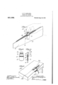
- Figure 1 is a perspective view of a portion of a saw showing the manner in which my improved saw jointer is used
- Fig. 2 is a side view of the file-holder;
- Fig. 3 is substantially a section on the line x-:c,
- Fig. 1 Fig. 4 shows the manner in which the device may be used as a gage.
- My improved jointer is formed of a single piece of sheet metal which is bent into the desired shape.
- the completed jointer or file-holder is formed with the two arms or side pieces 3 which form between them a space to receive the saw 4 and each of which is bent outwardly at 5 to form the file-receiving opening or ocket 6.
- the two sides of the jointer are bent into close proximity with each other and then are shaped to form the rounded portion 8 which constitutes a pencil-receiving recess.
- the device is made of resilient material.
- a file 10 preferably a three-cornered file
- a file-receiving pocket 6 as shown in Figs. 1 and 3, the two faces of the file resting against the fiat sides of the pocket and the ,third face of the file standing square across the jointer in position to act on the ends of the saw teeth.
- the file After the file has thus been inserted into the holder, it is placed over the saw, the two side pieces 3 embracing the sides of the saw and acting to guide the j ointer in its movement over the saw.
- the operator grasps the two sides with the thumb and fore finger, as shown in dotted lines Fig. 1, and allows the palm of the hand to rest on the top of the file. In this way the file may be held in its proper position and yet sufficient pressure may be a plied thereto to properly accomplish the esired object.
- the sides thereof will be resilient at the point 7 above the file-receiving pocket and again at the point immediately below the file-receiving pocket, so that files of different sizes may be readily used. If a larger file than that shown in the drawings is used, the resiliency of the sides permits the portions 3 to be closed onto the sidgs of the saw, so as to properly guide the too My improved device is also ca able of use as a gage, as shown in Fig. 4.
- the file is removed and a pencil 20 is inserted into the encil-receiving recess 11, and the sides of t 1e device may then be grasped by the operator with his thumb and fore finger and pinched together, thus causing the pencil to be gripped firmly.
- the edge of the holder may then be brought against the corner or edge of a block or board 12 on which a mark 13 is to-be made parallel to the edge and by passing the device along the edge of the block in a manner similar to that in which a gage is operated, the desired line 13 will be made.
- edges of the device may be notched where the file-receiving pocket 6 terminates, and this notch makes a convenient guide to engage the edge of the board.
- My improved device is comparatively fiat and thin and is constructed without sharp corners so that it can be readily carried in a persons pocket without inconvenience and without injuring the clothing.
Landscapes
- Engineering & Computer Science (AREA)
- Mechanical Engineering (AREA)
- Details Of Garments (AREA)
Description
E. W. GAMPAGNA.
POCKET SAW JOINTER.
APPLICATION 31mm MAY 15, 190B.
Patented Aug. 24, 1909.
EUGENE W. GAMPAG-NA, OF RANDOLPH, MASSACHUSETTS.
POCKET SAW-JOINTER.
Specification of Letters Patent.
Application filed. May 15, 1908.
Patented Aug. 24, 1909. Serial No. 433,022.
To all whom it may concern:
Be it known that I, EUGENE W. CAM- PAGNA, a citizen of the United States, residing at Randolph, county of Norfolk, and State of Massachusetts, have invented an Improvement in Pocket Saw-Jointers, of which the following description, in connection with the accompanying drawing, is a specification, like figures on the drawing representing like parts.
This invention relates to saw jointers adapted to level and even up the teeth of saws after they have become worn, and the invention has for its particular object to provide a novel device for holding the file by which the jointing operation is accomplished, all as will be more fully hereinafter described and then pointed out in the claim.
The drawings sli'ow a saw jointer embodying my invention and the manner in which it is used.
Figure 1 is a perspective view of a portion of a saw showing the manner in which my improved saw jointer is used Fig. 2 is a side view of the file-holder; Fig. 3 is substantially a section on the line x-:c, Fig. 1 Fig. 4 shows the manner in which the device may be used as a gage.
My improved jointer is formed of a single piece of sheet metal which is bent into the desired shape. The completed jointer or file-holder is formed with the two arms or side pieces 3 which form between them a space to receive the saw 4 and each of which is bent outwardly at 5 to form the file-receiving opening or ocket 6. Immediately above the file-receivlng pocket 6 the two sides of the jointer are bent into close proximity with each other and then are shaped to form the rounded portion 8 which constitutes a pencil-receiving recess.
The device is made of resilient material. In using it as a saw jointer, a file 10, preferably a three-cornered file, is inserted into the file-receiving pocket 6, as shown in Figs. 1 and 3, the two faces of the file resting against the fiat sides of the pocket and the ,third face of the file standing square across the jointer in position to act on the ends of the saw teeth. After the file has thus been inserted into the holder, it is placed over the saw, the two side pieces 3 embracing the sides of the saw and acting to guide the j ointer in its movement over the saw.
In using the device, the operator grasps the two sides with the thumb and fore finger, as shown in dotted lines Fig. 1, and allows the palm of the hand to rest on the top of the file. In this way the file may be held in its proper position and yet sufficient pressure may be a plied thereto to properly accomplish the esired object.
Owing to the fact that the device is made of resilient material, the sides thereof will be resilient at the point 7 above the file-receiving pocket and again at the point immediately below the file-receiving pocket, so that files of different sizes may be readily used. If a larger file than that shown in the drawings is used, the resiliency of the sides permits the portions 3 to be closed onto the sidgs of the saw, so as to properly guide the too My improved device is also ca able of use as a gage, as shown in Fig. 4. hen used in this way, the file is removed and a pencil 20 is inserted into the encil-receiving recess 11, and the sides of t 1e device may then be grasped by the operator with his thumb and fore finger and pinched together, thus causing the pencil to be gripped firmly. The edge of the holder may then be brought against the corner or edge of a block or board 12 on which a mark 13 is to-be made parallel to the edge and by passing the device along the edge of the block in a manner similar to that in which a gage is operated, the desired line 13 will be made.
If desired the edges of the device may be notched where the file-receiving pocket 6 terminates, and this notch makes a convenient guide to engage the edge of the board.
My improved device is comparatively fiat and thin and is constructed without sharp corners so that it can be readily carried in a persons pocket without inconvenience and without injuring the clothing.
Having fully described my invention, what I claim as new and desire to secure by Let- V ters Patent is A saw jointer made from a single piece of resilient sheet metal doubled on itself to present two sides adapted to embrace a saw} name to this specification, in the presence of and else to dreslint a pincil-receivinglportion Q two subscribing Witnesses. 11, eaci s1 e eing ent outward y at 5 thereby to form a file-receiving pocket said EUGENE CAMPAGNA' 5 sides being resilient at points both above and Witnesses:
below the file-receiving pocket. l EMILY O. HODGES,
In testimony whereof, I have signed my i FREDERICK S. GREENLEAF.
Priority Applications (1)
| Application Number | Priority Date | Filing Date | Title |
|---|---|---|---|
| US43302208A US931992A (en) | 1908-05-15 | 1908-05-15 | Pocket saw-jointer. |
Applications Claiming Priority (1)
| Application Number | Priority Date | Filing Date | Title |
|---|---|---|---|
| US43302208A US931992A (en) | 1908-05-15 | 1908-05-15 | Pocket saw-jointer. |
Publications (1)
| Publication Number | Publication Date |
|---|---|
| US931992A true US931992A (en) | 1909-08-24 |
Family
ID=3000416
Family Applications (1)
| Application Number | Title | Priority Date | Filing Date |
|---|---|---|---|
| US43302208A Expired - Lifetime US931992A (en) | 1908-05-15 | 1908-05-15 | Pocket saw-jointer. |
Country Status (1)
| Country | Link |
|---|---|
| US (1) | US931992A (en) |
Cited By (1)
| Publication number | Priority date | Publication date | Assignee | Title |
|---|---|---|---|---|
| US3762046A (en) * | 1971-05-03 | 1973-10-02 | P Kolomick | Hand tool for edging gypsum board |
-
1908
- 1908-05-15 US US43302208A patent/US931992A/en not_active Expired - Lifetime
Cited By (1)
| Publication number | Priority date | Publication date | Assignee | Title |
|---|---|---|---|---|
| US3762046A (en) * | 1971-05-03 | 1973-10-02 | P Kolomick | Hand tool for edging gypsum board |
Similar Documents
| Publication | Publication Date | Title |
|---|---|---|
| US1462714A (en) | Pencil-holding clip | |
| US2753105A (en) | Package opener | |
| US1724069A (en) | Tailor's kit | |
| US922954A (en) | Device for facilitating the dealing of cards. | |
| US2475021A (en) | T-square holding clip | |
| US945771A (en) | Blade holder and sharpener. | |
| US523380A (en) | Combined gage and finger-guard | |
| US2879778A (en) | Shaving guide for trimming sideburns | |
| US4500221A (en) | Marker holder apparatus | |
| US2693384A (en) | Philatelic tool | |
| US2535170A (en) | Bobby pin opener | |
| US1965814A (en) | Stamping element | |
| US2198530A (en) | Woodworking plane | |
| US1538227A (en) | Crosscut-saw jointer | |
| US1380410A (en) | Finger fence and protector | |
| US4040184A (en) | Cutting instrument | |
| US1521908A (en) | Tool guide | |
| US487239A (en) | Blotter | |
| US1383627A (en) | Safety-razor-blade holder | |
| US822553A (en) | Combination-tool. | |
| US3365011A (en) | Letter balance | |
| US935670A (en) | Clasp. | |
| US773782A (en) | Knife. | |
| US689940A (en) | Dental finger-guard. | |
| US1744856A (en) | Feeler gauge |