US931771A - Hanger for trolley-wires. - Google Patents
Hanger for trolley-wires. Download PDFInfo
- Publication number
- US931771A US931771A US44291808A US1908442918A US931771A US 931771 A US931771 A US 931771A US 44291808 A US44291808 A US 44291808A US 1908442918 A US1908442918 A US 1908442918A US 931771 A US931771 A US 931771A
- Authority
- US
- United States
- Prior art keywords
- hanger
- trolley
- wires
- secured
- portions
- Prior art date
- Legal status (The legal status is an assumption and is not a legal conclusion. Google has not performed a legal analysis and makes no representation as to the accuracy of the status listed.)
- Expired - Lifetime
Links
Images
Classifications
-
- H—ELECTRICITY
- H02—GENERATION; CONVERSION OR DISTRIBUTION OF ELECTRIC POWER
- H02G—INSTALLATION OF ELECTRIC CABLES OR LINES, OR OF COMBINED OPTICAL AND ELECTRIC CABLES OR LINES
- H02G7/00—Overhead installations of electric lines or cables
- H02G7/18—Devices affording mechanical protection in the event of breakage of a line or cable, e.g. net for catching broken lines
Definitions
- This invention relates to hangers for supporting trolley wires from guy or supportmg wires.
- the object of the invention is to provide a hanger of this character designed, in the event of the breakage of the trolley wires supported thereby, to automatically cut out the broken portion of the wire from the circuit and thus prevent injury such as often results from the breaking of wires.
- Another object is to provide a hanger which is simple and durable in construction, which can be readily substituted for the hangers ordinarily used and which is comparatively cheap to manufacture.
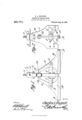
- Figure l is a side elevation of a hanger embodying the present improvements, a portion thereof being shown in section and one of the positions of one of the movable contacts being indicated by dotted lines.
- Fig. 2 is a front elevation of the hanger.
- the head of the same having a longitudinal groove in one face thereof as indicated at 2, said groove being designed to receive a guy A which may be fastened within the groove in any preferred manner as by means of a set screw 3 threaded into the upper end of the head 1.
- the lower end of the head is forked as shown at 4 and embraces, and is bolted or otherwise secured to the body 5 of the hanger which body is preferably formed of fiber or other strong non-conducting material.
- This body may be of any pre ferred contour and secured to one face thereof adjacent one side edge is a bracket 6 while another bracket 7 is secured upon the other face of'the body ad acent its other side edge.
- Each of these brackets has its outer end forked as shown at 8, the forked portions being disposed in alineinent but insulated from each other by the body
- a lever 9 is fulcrumed in the forked end of each bracket 67 and the lower ends of these levers are enlarged as indicated at 10, said enlarged portions being formed with alining grooves 11 and disposed adjacent a recess 12 formed in the lower end of body 5 and into which the enlarged portions are designed to swing.
- a plug 13 constituting a fixed contact extends through body 5 above the brackets 6 and the ends of this plug are designed to be contacted by buttons or enlargements 14 formed at the upper ends of levers 9.
- the trolley wire D is made up of sect-ions, the length of each section being equal to the distance between the bodies 5 of two adjoining hangers.
- the ends of the trolley sections B are seated within the grooves 11 and held in place therein by clenching the walls of the grooves thereonto or in any other preferred manner.
- Each section B is sufficiently taut to hold the levers 9 to which it is attached normally in contact with their plugs 13 and it will be seen therefore that when all of the sections of a trolley wire have been placed in this manner a current of electricity passing through them must necessarily pass through the levers 9 and the plugs 13 in order to complete a circuit.
- hanger herein described is not restricted for use in connection with trolley wires only, as it can be employed for supporting electrical conductors used for any purposes.
- a hanger comprising a flat non-conducting body having an arched lower end, a conducting plug extending through the body and beyond opposite faces thereof, nonalining brackets secured to opposite faces of the body and at opposite sides of the arch, contacts pivotally mounted within the Patented Aug. 24., 1909.
- brackets spaced Wires secured to the lower portions of the contacts and normally holding the upper portions of said contacts in position upon the conducting plug, the lower portions of said movable contacts Lbeing spaced apart, the upper portion of the arch of the body constituting a stop for the contacts in the event of the breakage of a Wire section or sections, a head secured to the body 10 and having a guy-receiving groove in one face thereof, and means within the head for binding a guy Within the groove.
Landscapes
- Particle Accelerators (AREA)
Description
G. A. KRAYNIK.
HANG-EB FOR TROLLEY WIRES. APPLIOATION FILED JULY 10, 1908.
Patented Aug. 24, 1909.
CHARLES A. KRAYNIK, 0F RAGINE, WISCONSIN.
HANGER FOR TROLLEY-WIRE S.
Specification of Letters Patent.
Application filed July 10, 1908. Serial N 0. 442,918.
To all whom it may concern:
Be it known that I, CHARLES A. KRAYNIK, a citizen of the United States, residing at Racine, in the county of Racine and State of lVisconsin, have invented a new and useful Hanger for TrolleydVires, of which the following is a specification.
This invention relates to hangers for supporting trolley wires from guy or supportmg wires.
The object of the invention is to provide a hanger of this character designed, in the event of the breakage of the trolley wires supported thereby, to automatically cut out the broken portion of the wire from the circuit and thus prevent injury such as often results from the breaking of wires.
Another object is to provide a hanger which is simple and durable in construction, which can be readily substituted for the hangers ordinarily used and which is comparatively cheap to manufacture.
ith these and other objects in View the invention consists in certain novel features of construction and combinations of parts which will be hereinafter more fully described and pointed out in the claim.
In the accompanying drawings is shown the preferred form of the invention.
In said drawings: Figure l is a side elevation of a hanger embodying the present improvements, a portion thereof being shown in section and one of the positions of one of the movable contacts being indicated by dotted lines. Fig. 2 is a front elevation of the hanger.
Referring to the figures by characters of reference, 1
designates the head of the same having a longitudinal groove in one face thereof as indicated at 2, said groove being designed to receive a guy A which may be fastened within the groove in any preferred manner as by means of a set screw 3 threaded into the upper end of the head 1. The lower end of the head is forked as shown at 4 and embraces, and is bolted or otherwise secured to the body 5 of the hanger which body is preferably formed of fiber or other strong non-conducting material. This body may be of any pre ferred contour and secured to one face thereof adjacent one side edge is a bracket 6 while another bracket 7 is secured upon the other face of'the body ad acent its other side edge. Each of these brackets has its outer end forked as shown at 8, the forked portions being disposed in alineinent but insulated from each other by the body A lever 9 is fulcrumed in the forked end of each bracket 67 and the lower ends of these levers are enlarged as indicated at 10, said enlarged portions being formed with alining grooves 11 and disposed adjacent a recess 12 formed in the lower end of body 5 and into which the enlarged portions are designed to swing. A plug 13 constituting a fixed contact extends through body 5 above the brackets 6 and the ends of this plug are designed to be contacted by buttons or enlargements 14 formed at the upper ends of levers 9.
In using the hanger herein described the same is placed with a guy wire A seated within groove 2 and held therein by set screw 3. The trolley wire D is made up of sect-ions, the length of each section being equal to the distance between the bodies 5 of two adjoining hangers. The ends of the trolley sections B are seated within the grooves 11 and held in place therein by clenching the walls of the grooves thereonto or in any other preferred manner. Each section B is sufficiently taut to hold the levers 9 to which it is attached normally in contact with their plugs 13 and it will be seen therefore that when all of the sections of a trolley wire have been placed in this manner a current of electricity passing through them must necessarily pass through the levers 9 and the plugs 13 in order to complete a circuit. Should one of the sections B break from any cause and fall to the ground the weight of the broken portions will be sutficient to swing the levers to which they are connected out of contact with their plugs 13 and the broken sectionswill therefore be promptly cut out of circuit and danger of injury therefrom eliminated.
It is of course to be understood that the hanger herein described is not restricted for use in connection with trolley wires only, as it can be employed for supporting electrical conductors used for any purposes.
What is claimed is:
A hanger comprising a flat non-conducting body having an arched lower end, a conducting plug extending through the body and beyond opposite faces thereof, nonalining brackets secured to opposite faces of the body and at opposite sides of the arch, contacts pivotally mounted within the Patented Aug. 24., 1909.
brackets, spaced Wires secured to the lower portions of the contacts and normally holding the upper portions of said contacts in position upon the conducting plug, the lower portions of said movable contacts Lbeing spaced apart, the upper portion of the arch of the body constituting a stop for the contacts in the event of the breakage of a Wire section or sections, a head secured to the body 10 and having a guy-receiving groove in one face thereof, and means within the head for binding a guy Within the groove.
lnitestinionythat I claim the foregoing as my own, I have hereto afiixed my signature inathe presence of tWo Witnesses.
CHARLES A. KRAYNIK.
\Vitnesses:
J OI-IN H. LIEGLER, ALBERT E. ANDERSON.
Priority Applications (1)
| Application Number | Priority Date | Filing Date | Title |
|---|---|---|---|
| US44291808A US931771A (en) | 1908-07-10 | 1908-07-10 | Hanger for trolley-wires. |
Applications Claiming Priority (1)
| Application Number | Priority Date | Filing Date | Title |
|---|---|---|---|
| US44291808A US931771A (en) | 1908-07-10 | 1908-07-10 | Hanger for trolley-wires. |
Publications (1)
| Publication Number | Publication Date |
|---|---|
| US931771A true US931771A (en) | 1909-08-24 |
Family
ID=3000195
Family Applications (1)
| Application Number | Title | Priority Date | Filing Date |
|---|---|---|---|
| US44291808A Expired - Lifetime US931771A (en) | 1908-07-10 | 1908-07-10 | Hanger for trolley-wires. |
Country Status (1)
| Country | Link |
|---|---|
| US (1) | US931771A (en) |
Cited By (1)
| Publication number | Priority date | Publication date | Assignee | Title |
|---|---|---|---|---|
| US3582585A (en) * | 1968-06-25 | 1971-06-01 | Guy Otis Stenstrom Jr | Safety of electric transmission and distribution |
-
1908
- 1908-07-10 US US44291808A patent/US931771A/en not_active Expired - Lifetime
Cited By (1)
| Publication number | Priority date | Publication date | Assignee | Title |
|---|---|---|---|---|
| US3582585A (en) * | 1968-06-25 | 1971-06-01 | Guy Otis Stenstrom Jr | Safety of electric transmission and distribution |
Similar Documents
| Publication | Publication Date | Title |
|---|---|---|
| US1398005A (en) | Trolley-wire protector | |
| US470382A (en) | Safety cut-out | |
| US746437A (en) | Hanger for trolley-wires. | |
| US1248728A (en) | Trolley-hanger for grade-crossing bridges. | |
| US398661A (en) | Insulating-support for electric conductors | |
| US622618A (en) | System for overhead electric wires | |
| US799726A (en) | Insulator. | |
| US426203A (en) | munsie | |
| US1181477A (en) | Trolley-conductor. | |
| US760305A (en) | Coupling for electric wires. | |
| US770962A (en) | Insulator. | |
| US1034888A (en) | Section-insulator for overhead structures. | |
| US469253A (en) | Automatic disconnector | |
| US303483A (en) | Teeeitoey | |
| US945972A (en) | Catenary suspension for trolley-wires and the like. | |
| US476828A (en) | Circuit-breaking insulator | |
| US497104A (en) | Automatic switch for mast-arms | |
| US435098A (en) | Automatic disconnector for overhead conductors | |
| US774534A (en) | Trolley. | |
| US519519A (en) | Trolley-wire crossing | |
| US575952A (en) | Frank hoover | |
| US866646A (en) | Contact device. | |
| US1100614A (en) | Wire-tapper. | |
| US725044A (en) | Insulator. | |
| US1580047A (en) | Disconnecting switch |