US9316082B2 - Well cap assembly - Google Patents
Well cap assembly Download PDFInfo
- Publication number
- US9316082B2 US9316082B2 US13/815,156 US201313815156A US9316082B2 US 9316082 B2 US9316082 B2 US 9316082B2 US 201313815156 A US201313815156 A US 201313815156A US 9316082 B2 US9316082 B2 US 9316082B2
- Authority
- US
- United States
- Prior art keywords
- plate
- clamping plate
- gaskets
- cap assembly
- top plate
- Prior art date
- Legal status (The legal status is an assumption and is not a legal conclusion. Google has not performed a legal analysis and makes no representation as to the accuracy of the status listed.)
- Active, expires
Links
Images


Classifications
-
- E—FIXED CONSTRUCTIONS
- E21—EARTH DRILLING; MINING
- E21B—EARTH DRILLING, e.g. DEEP DRILLING; OBTAINING OIL, GAS, WATER, SOLUBLE OR MELTABLE MATERIALS OR A SLURRY OF MINERALS FROM WELLS
- E21B33/00—Sealing or packing boreholes or wells
- E21B33/02—Surface sealing or packing
- E21B33/03—Well heads; Setting-up thereof
- E21B33/04—Casing heads; Suspending casings or tubings in well heads
-
- E—FIXED CONSTRUCTIONS
- E21—EARTH DRILLING; MINING
- E21B—EARTH DRILLING, e.g. DEEP DRILLING; OBTAINING OIL, GAS, WATER, SOLUBLE OR MELTABLE MATERIALS OR A SLURRY OF MINERALS FROM WELLS
- E21B33/00—Sealing or packing boreholes or wells
- E21B33/02—Surface sealing or packing
Definitions
- This invention relates to an assembly for sealing the open end of a pipe. More specifically, the invention relates to a well cap assembly for sealing the top end of a well casing, which is used to extract a fluid from the ground.
- the assembly of the present invention was designed to seal the top end of a well casing at a landfill site, it will be appreciated that the assembly can be used on other pipes or conduits such as the casings of oil or gas wells.
- a literature search discloses a variety of pipe seals including those described in U.S. Pat. No. 3,494,504, issued to J. C. Jackson on Feb. 10, 1970; U.S. Pat. No. 3,667,640, issued to Joseph. G. Morrow on Jun. 6, 1972; U.S. Pat. No. 3,901,167, issued to Dale C. Reese on Aug. 26, 1975; U.S. Pat. No. 4,175,671 issued to Harold H. Holl et al on Nov. 27, 1979; U.S. Pat. No. 4,303,101, issued to James W. T noir on Dec. 1, 1981; U.S. Pat. No. 4,415,005, issued to Harlo W. Jahzen on Nov. 15, 1983; U.S. Pat.
- the cap assembly of the present invention provides a solution to the above-identified problems. Moreover, the cap assembly of the present invention is structurally simple and easy and inexpensive to manufacture.
- the cap assembly of the present invention includes:
- a thick top plate for mounting on the top end of a well casing or on the open end of another pipe
- a plurality of sleeves extend between the upper and lower clamping plates for maintaining a fixed spacing between the clamping plates
- the top plate moves towards the upper clamping plate to compress the first gasket causing it to expand radially outwardly to create a seal at the top end of the casing
- the bottom plate moves toward the lower clamping plate to compress the second gasket, causing it to expand radially outwardly to create a seal at a location beneath and spaced part from such lop end of the casing.
- the well cap assembly seals the top end of a casing at two separate spaced apart locations, one immediately beneath the top end and the other a short distance beneath such top end of the casing.
- FIG. 1 is an isometric view of a well cap assembly in accordance with the present invention
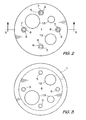
- FIG. 2 is top view of the well cap assembly of FIG. 1 ;
- FIG. 3 is a bottom view of the well cap assembly of FIGS. 1 and 2 ;
- FIG. 4 is a side view of the well cap assembly of FIGS. 1 to 3 mounted on a well casing;
- FIG. 5 is a cross section of the well cap assembly taken generally along line 5 - 5 of FIG. 1 .
- the well cap assembly of the present invention includes a thick top plate 1 for mounting on the top end 2 of a well casing 3 ( FIGS. 4 and 5 ).
- the top plate 1 is formed of powder coated or stainless steel, and has a diameter larger than the outside diameter of the casing 3 on which it is mounted.
- a thinner, steel bottom plate 4 is connected to the top plate 1 by bolts 5 , washers 6 and nuts 7 .
- the bolts 5 extend upwardly through the bottom plate 4 , a pair of expansible lower gaskets 9 , a lower clamping plate 10 , steel spacer sleeves 11 , an upper clamping plate 12 , three expansible upper gaskets 13 and the top plate 1 .
- the gaskets 9 and 13 are formed of a synthetic rubber such as nitrile or EPDM (ethylene propylene diene monomer) rubber.
- the reason for using a plurality of thin gaskets 9 and 13 is that the durometer rating (hardness) of such gaskets is consistent over the entire area of the gaskets which is not always the case with a thick gasket.
- a single thick gasket could be used, it is preferable to use a plurality of thin, expansible gaskets sandwiched together.
- Access openings 15 are provided in the top and bottom plates 1 and 4 , respectively and in the gaskets 9 and 13 .
- the openings are intended to receive pipes (not shown) for removing fluid from the well, sampling, pressure monitoring and other purposes. If the cap assembly is used solely to seal the top end of a well casing or the open end of another pipe, there are no openings 15 in the various layers of the assembly.
- the preferred dimensions of the various elements of the cap assembly are as follows: the top plate 1 has a diameter of 5 inches and a thickness of 0.375 inch; each of the bottom plate 4 , the gaskets 9 and 13 , and the clamping plates 10 and 12 has a diameter of 3.73 inches and a thickness of 25 inch; and each spacer sleeve 11 has a length of 2 inches.
- the preferred dimensions of the elements of the cap assembly are as follows: the top plate has a diameter of 7.125 inches and a thickness of 0.375 inch; each of the bottom plate 4 and the clamping plates 10 and 12 has a diameter of 5.636 inches and a thickness of 0.25 inch; each of the gaskets 9 and 13 has a diameter of 5.64 inches and a thickness of 0.25 inch; and each spacer sleeve 11 has a length of 2 inches.
- the preferred dimensions of the elements of the cap assembly are as follows: the top plate has a diameter of 9.125 inches and a thickness of 0.375 inch; each of the bottom plate 4 , the gaskets 9 and 13 and the clamping plates 10 and 12 has a diameter of 7.49 inches and a thickness of 0.25 inch; and each spacer sleeve 11 has a length of 2 inches.
- the assembly In use, the assembly is placed on the top end 2 of the well casing 3 or in the open end of any other pipe (not shown) to be sealed.
- the nuts 7 are tightened on the bolts 5 , causing the top plate 1 to move towards the clamping plate 12 , and the bottom plate 4 , to move towards the clamping plate 10 .
- the clamping plates 10 and 12 cannot move relative to each other. The result is that the expansible gaskets 9 and 13 are compressed, causing them to expand radially against the interior wall of the casing 3 and to seal against the bolts 5 .
- the top plate 1 , the bottom plate 4 , the clamping plates 10 and 12 and the gaskets 9 and 13 contain openings 15 with pipes therein, the gaskets 9 and 13 also seal against the pipes.
Abstract
Description
Claims (3)
Priority Applications (1)
| Application Number | Priority Date | Filing Date | Title |
|---|---|---|---|
| US13/815,156 US9316082B2 (en) | 2013-02-05 | 2013-02-05 | Well cap assembly |
Applications Claiming Priority (1)
| Application Number | Priority Date | Filing Date | Title |
|---|---|---|---|
| US13/815,156 US9316082B2 (en) | 2013-02-05 | 2013-02-05 | Well cap assembly |
Publications (2)
| Publication Number | Publication Date |
|---|---|
| US20140216716A1 US20140216716A1 (en) | 2014-08-07 |
| US9316082B2 true US9316082B2 (en) | 2016-04-19 |
Family
ID=51258299
Family Applications (1)
| Application Number | Title | Priority Date | Filing Date |
|---|---|---|---|
| US13/815,156 Active 2033-12-25 US9316082B2 (en) | 2013-02-05 | 2013-02-05 | Well cap assembly |
Country Status (1)
| Country | Link |
|---|---|
| US (1) | US9316082B2 (en) |
Families Citing this family (2)
| Publication number | Priority date | Publication date | Assignee | Title |
|---|---|---|---|---|
| GB2554935A (en) * | 2016-10-14 | 2018-04-18 | Mcgarian Bruce | An apparatus for sealing a pipe |
| WO2024007462A1 (en) * | 2022-07-06 | 2024-01-11 | 昊星宇(天津)科技发展有限公司 | Isolation packer device of novel sealing structure for heavy oil thermal recovery well |
Citations (6)
| Publication number | Priority date | Publication date | Assignee | Title |
|---|---|---|---|---|
| US2090213A (en) * | 1936-11-25 | 1937-08-17 | Fairbanks Morse & Co | Well seal |
| US3568769A (en) * | 1969-07-07 | 1971-03-09 | Herbert W Maass | Well casing cap |
| US5111879A (en) * | 1990-06-06 | 1992-05-12 | Amtrol Inc. | Sanitary locking lip split well seal |
| US5437309A (en) * | 1994-03-15 | 1995-08-01 | Timmons; Robert D. | Lockable well cap |
| US5664626A (en) * | 1995-06-06 | 1997-09-09 | Watts, Iii; William F. | Mechanical plug device |
| US20130048312A1 (en) * | 2011-08-24 | 2013-02-28 | Francis Walls | Pipe End Plug Apparatus and Method |
-
2013
- 2013-02-05 US US13/815,156 patent/US9316082B2/en active Active
Patent Citations (6)
| Publication number | Priority date | Publication date | Assignee | Title |
|---|---|---|---|---|
| US2090213A (en) * | 1936-11-25 | 1937-08-17 | Fairbanks Morse & Co | Well seal |
| US3568769A (en) * | 1969-07-07 | 1971-03-09 | Herbert W Maass | Well casing cap |
| US5111879A (en) * | 1990-06-06 | 1992-05-12 | Amtrol Inc. | Sanitary locking lip split well seal |
| US5437309A (en) * | 1994-03-15 | 1995-08-01 | Timmons; Robert D. | Lockable well cap |
| US5664626A (en) * | 1995-06-06 | 1997-09-09 | Watts, Iii; William F. | Mechanical plug device |
| US20130048312A1 (en) * | 2011-08-24 | 2013-02-28 | Francis Walls | Pipe End Plug Apparatus and Method |
Also Published As
| Publication number | Publication date |
|---|---|
| US20140216716A1 (en) | 2014-08-07 |
Similar Documents
| Publication | Publication Date | Title |
|---|---|---|
| EP2994682B1 (en) | Coupling for range of pipe diameters | |
| RU2697585C2 (en) | Sealing device | |
| US20170036830A1 (en) | Vacuum System And Seal | |
| US9316082B2 (en) | Well cap assembly | |
| KR102162670B1 (en) | Pipe connecting device for piping | |
| CA2883456C (en) | Seal assembly for a casing hanger | |
| US4268070A (en) | Orifice flange clamp | |
| CA2804699C (en) | Well cap assembly | |
| US7527299B1 (en) | Container discharge and fill port fitting | |
| KR200446817Y1 (en) | A metal ring of piping with gasket groove | |
| KR101854780B1 (en) | Vacuum pipe support apparatus for semiconductor and display manufacturing device | |
| RU105712U1 (en) | WELL FOR OBSERVING THE WORK OF THE PIPELINE AND ITS EQUIPMENT | |
| CN103939447B (en) | A kind of double seal bolt | |
| KR20150001579U (en) | Gasket for high pressure pipe | |
| KR20140004390U (en) | Packing Jig for Pipe Air Test | |
| RU2731006C1 (en) | Fastening elements on pipe | |
| KR20200137094A (en) | Pipe coupling easy installed | |
| KR101836447B1 (en) | Manhole improved ability of watertightness | |
| RU2010113160A (en) | HIGH PRESSURE FLANGE CONNECTION WITH DIELECTRIC PIPELINE CONNECTOR | |
| JP6428239B2 (en) | Electromagnetic flow meter | |
| US11054155B2 (en) | Resin-coated aluminum pipe connector for air conditioner outdoor unit | |
| JP3195805U (en) | Pipe end face seal | |
| CN205118504U (en) | Flange that leakproofness is good | |
| CN205013909U (en) | Can prevent steel pipe connection that flexible rubber hose drops | |
| RU160831U1 (en) | HEAD |
Legal Events
| Date | Code | Title | Description |
|---|---|---|---|
| STCF | Information on status: patent grant |
Free format text: PATENTED CASE |
|
| AS | Assignment |
Owner name: ATZ APPLIED TECHNOLOGIES INC., CANADA Free format text: ASSIGNMENT OF ASSIGNORS INTEREST;ASSIGNOR:NIELSEN, CHRISTOPHER;REEL/FRAME:040674/0026 Effective date: 20161130 Owner name: ATZ APPLIED TECHNOLOGIES INC., CANADA Free format text: ASSIGNMENT OF ASSIGNORS INTEREST;ASSIGNOR:NIELSEN, CHRISTOPHER;REEL/FRAME:040817/0918 Effective date: 20161130 |
|
| AS | Assignment |
Owner name: Q.E.D. ENVIRONMENTAL SYSTEMS, INC., MICHIGAN Free format text: ASSIGNMENT OF ASSIGNORS INTEREST;ASSIGNOR:ATZ APPLIED TECHNOLOGIES INC.;REEL/FRAME:043575/0728 Effective date: 20161222 |
|
| FEPP | Fee payment procedure |
Free format text: ENTITY STATUS SET TO UNDISCOUNTED (ORIGINAL EVENT CODE: BIG.); ENTITY STATUS OF PATENT OWNER: LARGE ENTITY |
|
| MAFP | Maintenance fee payment |
Free format text: PAYMENT OF MAINTENANCE FEE, 4TH YEAR, LARGE ENTITY (ORIGINAL EVENT CODE: M1551); ENTITY STATUS OF PATENT OWNER: LARGE ENTITY Year of fee payment: 4 |
|
| MAFP | Maintenance fee payment |
Free format text: PAYMENT OF MAINTENANCE FEE, 8TH YEAR, LARGE ENTITY (ORIGINAL EVENT CODE: M1552); ENTITY STATUS OF PATENT OWNER: LARGE ENTITY Year of fee payment: 8 |