US9313014B2 - Radio communication system, radio communication method, radio base station apparatus and user terminal - Google Patents
Radio communication system, radio communication method, radio base station apparatus and user terminal Download PDFInfo
- Publication number
- US9313014B2 US9313014B2 US14/234,438 US201214234438A US9313014B2 US 9313014 B2 US9313014 B2 US 9313014B2 US 201214234438 A US201214234438 A US 201214234438A US 9313014 B2 US9313014 B2 US 9313014B2
- Authority
- US
- United States
- Prior art keywords
- base station
- radio base
- station apparatus
- user terminal
- cells
- Prior art date
- Legal status (The legal status is an assumption and is not a legal conclusion. Google has not performed a legal analysis and makes no representation as to the accuracy of the status listed.)
- Active, expires
Links
- 238000004891 communication Methods 0.000 title claims description 63
- 238000000034 method Methods 0.000 title claims description 51
- 230000005540 biological transmission Effects 0.000 claims abstract description 141
- 230000011664 signaling Effects 0.000 claims description 30
- 238000012545 processing Methods 0.000 description 29
- 230000008569 process Effects 0.000 description 26
- 238000010586 diagram Methods 0.000 description 20
- 238000013507 mapping Methods 0.000 description 13
- 230000004931 aggregating effect Effects 0.000 description 8
- 230000002776 aggregation Effects 0.000 description 6
- 238000004220 aggregation Methods 0.000 description 6
- 239000000969 carrier Substances 0.000 description 6
- 239000013256 coordination polymer Substances 0.000 description 5
- 125000004122 cyclic group Chemical group 0.000 description 5
- 238000012937 correction Methods 0.000 description 4
- 239000000284 extract Substances 0.000 description 4
- 230000003044 adaptive effect Effects 0.000 description 3
- 238000006243 chemical reaction Methods 0.000 description 3
- 238000003780 insertion Methods 0.000 description 3
- 230000037431 insertion Effects 0.000 description 3
- 101000741965 Homo sapiens Inactive tyrosine-protein kinase PRAG1 Proteins 0.000 description 2
- 102100038659 Inactive tyrosine-protein kinase PRAG1 Human genes 0.000 description 2
- 239000013307 optical fiber Substances 0.000 description 2
- 238000013468 resource allocation Methods 0.000 description 2
- 230000008901 benefit Effects 0.000 description 1
- 230000008878 coupling Effects 0.000 description 1
- 238000010168 coupling process Methods 0.000 description 1
- 238000005859 coupling reaction Methods 0.000 description 1
- 238000005562 fading Methods 0.000 description 1
- 230000007774 longterm Effects 0.000 description 1
- 238000007726 management method Methods 0.000 description 1
- 230000007246 mechanism Effects 0.000 description 1
- 238000012986 modification Methods 0.000 description 1
- 230000004048 modification Effects 0.000 description 1
- 230000003287 optical effect Effects 0.000 description 1
- 230000003595 spectral effect Effects 0.000 description 1
Images


Classifications
-
- H—ELECTRICITY
- H04—ELECTRIC COMMUNICATION TECHNIQUE
- H04L—TRANSMISSION OF DIGITAL INFORMATION, e.g. TELEGRAPHIC COMMUNICATION
- H04L5/00—Arrangements affording multiple use of the transmission path
- H04L5/0091—Signaling for the administration of the divided path
-
- H—ELECTRICITY
- H04—ELECTRIC COMMUNICATION TECHNIQUE
- H04J—MULTIPLEX COMMUNICATION
- H04J11/00—Orthogonal multiplex systems, e.g. using WALSH codes
- H04J11/0023—Interference mitigation or co-ordination
- H04J11/005—Interference mitigation or co-ordination of intercell interference
- H04J11/0053—Interference mitigation or co-ordination of intercell interference using co-ordinated multipoint transmission/reception
-
- H—ELECTRICITY
- H04—ELECTRIC COMMUNICATION TECHNIQUE
- H04L—TRANSMISSION OF DIGITAL INFORMATION, e.g. TELEGRAPHIC COMMUNICATION
- H04L5/00—Arrangements affording multiple use of the transmission path
- H04L5/0001—Arrangements for dividing the transmission path
- H04L5/0003—Two-dimensional division
- H04L5/0005—Time-frequency
- H04L5/0007—Time-frequency the frequencies being orthogonal, e.g. OFDM(A), DMT
- H04L5/001—Time-frequency the frequencies being orthogonal, e.g. OFDM(A), DMT the frequencies being arranged in component carriers
-
- H—ELECTRICITY
- H04—ELECTRIC COMMUNICATION TECHNIQUE
- H04L—TRANSMISSION OF DIGITAL INFORMATION, e.g. TELEGRAPHIC COMMUNICATION
- H04L5/00—Arrangements affording multiple use of the transmission path
- H04L5/003—Arrangements for allocating sub-channels of the transmission path
- H04L5/0032—Distributed allocation, i.e. involving a plurality of allocating devices, each making partial allocation
- H04L5/0035—Resource allocation in a cooperative multipoint environment
-
- H—ELECTRICITY
- H04—ELECTRIC COMMUNICATION TECHNIQUE
- H04L—TRANSMISSION OF DIGITAL INFORMATION, e.g. TELEGRAPHIC COMMUNICATION
- H04L5/00—Arrangements affording multiple use of the transmission path
- H04L5/003—Arrangements for allocating sub-channels of the transmission path
- H04L5/0053—Allocation of signaling, i.e. of overhead other than pilot signals
-
- H—ELECTRICITY
- H04—ELECTRIC COMMUNICATION TECHNIQUE
- H04B—TRANSMISSION
- H04B7/00—Radio transmission systems, i.e. using radiation field
- H04B7/02—Diversity systems; Multi-antenna system, i.e. transmission or reception using multiple antennas
- H04B7/022—Site diversity; Macro-diversity
- H04B7/024—Co-operative use of antennas of several sites, e.g. in co-ordinated multipoint or co-operative multiple-input multiple-output [MIMO] systems
-
- H—ELECTRICITY
- H04—ELECTRIC COMMUNICATION TECHNIQUE
- H04W—WIRELESS COMMUNICATION NETWORKS
- H04W36/00—Hand-off or reselection arrangements
- H04W36/0005—Control or signalling for completing the hand-off
- H04W36/0055—Transmission or use of information for re-establishing the radio link
- H04W36/0069—Transmission or use of information for re-establishing the radio link in case of dual connectivity, e.g. decoupled uplink/downlink
- H04W36/00692—Transmission or use of information for re-establishing the radio link in case of dual connectivity, e.g. decoupled uplink/downlink using simultaneous multiple data streams, e.g. cooperative multipoint [CoMP], carrier aggregation [CA] or multiple input multiple output [MIMO]
Definitions
- the present invention relates to a radio communication system, a radio communication method, a radio base station apparatus and a user terminal. More particularly, the present invention relates to a radio communication system, a radio communication method, a radio base station apparatus and a user terminal that perform coordinated multiple point (CoMP) transmission/reception in a system band that is formed by aggregating a plurality of fundamental frequency blocks.
- CoMP coordinated multiple point
- UMTS Universal Mobile Telecommunications System
- W-CDMA Wideband Code Division Multiple Access
- HSDPA High Speed Downlink Packet Access
- HSUPA High Speed Uplink Packet Access
- LTE long-term evolution
- the third-generation system it is possible to achieve a transmission rate of maximum approximately 2 Mbps on the downlink by using a fixed band of approximately 5 MHz. Meanwhile, in a system of the LTE scheme, it is possible to achieve a transmission rate of about maximum 300 Mbps on the downlink and about 75 Mbps on the uplink by using a variable band which ranges from 1.4 MHz to 20 MHz. Furthermore, in the UMTS network, for the purpose of achieving further broadbandization and higher speed, successor systems of LTE have been under study (for example, LTE-Advanced (LTE-A system)).
- LTE-A system LTE-Advanced
- the LTE-A system In the LTE-A system, aggregating a plurality of fundamental frequency blocks (component carriers (CCs)) of varying frequency bands for broadbandization (carrier aggregation (CA)) is under study. Also, in the LTE-A system, there is an agreement to make the fundamental frequency blocks a frequency band that can be used in the LTE system (for example, 20 MHz), in order to realize broadbandization while maintaining backward compatibility with the LTE system. For example, when five fundamental frequency blocks are aggregated, the system band becomes 100 MHz.
- CCs component carriers
- CA carrier aggregation
- inter-cell orthogonalization In the LTE-A system, intra-cell orthogonalization is made possible by orthogonal multiple access on both the uplink and the downlink. That is to say, on the downlink, orthogonalization is provided between user terminals (user equipment) in the frequency domain. However, between cells, like in W-CDMA, interference randomization by one-cell frequency reuse is fundamental.
- coordinated multiple-point transmission/reception In the 3GPP (3rd Generation Partnership Project), coordinated multiple-point transmission/reception (CoMP) is under study as a technique to realize inter-cell orthogonalization.
- CoMP transmission/reception a plurality of cells coordinate and perform signal processing for transmission and reception for one user terminal (UE) or for a plurality of user terminals (UEs).
- CoMP transmission/reception it is necessary to apply the same frequency band between cells that perform coordinated multiple-point transmission with respect to a user terminal.
- CoMP transmission/reception is applied between cells of different radio base station apparatuses, in a system band that is formed with a plurality of fundamental frequency blocks, the control for CoMP transmission/reception becomes complex.
- CoMP transmission/reception is applied to a configuration to perform data transmission with respect to a single limited fundamental frequency block, although it is possible to improve received quality in user terminals, it then becomes not possible to realize sufficient broadbandization.
- the present invention has been made in view of the above, and it is therefore an object of the present invention to provide a radio communication system, a radio communication method, a radio base station apparatus and a user terminal whereby, in a system band that is formed with a plurality of fundamental frequency blocks, it is possible to apply CoMP transmission/reception flexibly, improve received quality in user terminals, and also widen the system band.
- a radio communication system has: a first radio base station apparatus that transmits downlink data to a user terminal using a plurality of cells that respectively correspond to fundamental frequency blocks of varying frequency bands; and a second radio base station apparatus that transmits downlink data to the user terminal using a cell that corresponds to fundamental frequency block of a same frequency band as one of the plurality of cells, and, in this radio communication system: the user terminal receives the downlink data in a system band that is formed with cells that are selected respectively from the first radio base station apparatus and the second radio base station apparatus; and the first radio base station apparatus and the second radio base station apparatus perform coordinated multiple-point transmission for the user terminal, between the cells corresponding to a same fundamental frequency block, and also report information about a combination of cells that perform the coordinated multiple-point transmission to the user terminal.
- Another radio communication system has: a first radio base station apparatus that transmits downlink data to a user terminal using a plurality of cells that respectively correspond to fundamental frequency blocks of varying frequency bands; and a plurality of second radio base station apparatuses that have lower transmission power than the first radio base station apparatus and that also have coverage areas that are each included in a coverage area of the first radio base station apparatus, and, in this radio communication system: the plurality of the second radio base station apparatuses transmit downlink data to the user terminal by performing coordinated multiple-point transmission using cells that correspond to fundamental frequency blocks of a same frequency band; and the user terminal receives the downlink data transmitted from the plurality of the second radio base station apparatuses by coordinated multiple-point transmission.
- a radio communication method includes the steps of: at a first radio base station apparatus, transmitting downlink data to a user terminal using a plurality of cells that respectively correspond to fundamental frequency blocks of varying frequency bands; at a second radio base station apparatus, transmitting downlink data to the user terminal using a cell that corresponds to fundamental frequency block of a same frequency band as one of the plurality of cells; and at the user terminal, receiving the downlink data in a system band that is formed with cells that are selected respectively from the first radio base station apparatus and the second radio base station apparatus, and, in this radio communication method, the first radio base station apparatus and the second radio base station apparatus perform coordinated multiple-point transmission for the user terminal, between cells corresponding to a same fundamental frequency block, and also report information about a combination of cells that perform the coordinated multiple-point transmission to the user terminal.
- a radio base station apparatus is radio base station apparatus that transmits downlink data to a user terminal using a plurality of cells that respectively correspond to fundamental frequency blocks of varying frequency bands, and this radio base station apparatus has: a transmission control section that executes coordinated multiple-point transmission with the user terminal, between a predetermined cell selected from the plurality of cells, and a cell of another radio base station apparatus corresponding to a fundamental frequency block of a same frequency band as the predetermined cell; and an information generating section that generates information about a combination of cells that perform the coordinated multiple-point transmission.
- a user terminal is a user terminal that receives data transmitted from a plurality of radio base station apparatuses using a system band that is formed with a plurality of fundamental frequency blocks, and this user terminal has: a reception control section that receives downlink data that is transmitted from a plurality of radio base station apparatuses by coordinated multiple-point transmission between cells corresponding to fundamental frequency blocks of a same frequency band; and a determining section that demodulates the data transmitted from the plurality of radio base station apparatuses and determines a combination of cells that perform the coordinated multiple-point transmission.
- FIG. 1 provides diagrams to explain coordinated multiple points
- FIG. 2 provides diagrams to explain configurations of radio base station apparatuses
- FIG. 3 is a diagram showing a layered bandwidth configuration defined in LTE-A
- FIG. 4 provides diagrams to show an example of a configuration of a radio communication system according to the present embodiment
- FIG. 5 provides diagrams to show examples of a CIF that is used in cross-carrier scheduling in an LTE-A system
- FIG. 6 provides diagrams to show examples of data transmission when dynamic cell selection is adopted in a radio communication system according to the present embodiment
- FIG. 7 provides diagrams to show examples of data transmission when joint transmission is adopted in a radio communication system according to the present embodiment
- FIG. 8 is a diagram to show a case where CoMP is applied between low transmission power base stations in a radio communication system according to the present embodiment
- FIG. 9 provides diagrams to show an example of a configuration of a radio communication system according to the present embodiment.
- FIG. 10 is a diagram to explain a configuration of a radio communication system according to the present embodiment.
- FIG. 11 is a functional block diagram to show an overall configuration of a radio base station apparatus according to the present embodiment.
- FIG. 12 is a functional block diagram to show an overall configuration of a user terminal according to the present embodiment.
- FIG. 13 is a functional block diagram of a baseband processing section provided in a radio base station apparatus according to the present embodiment, and part of higher layers;
- FIG. 14 is a functional block diagram of a baseband processing section provided in a user terminal according to the present embodiment.
- Downlink CoMP transmission includes coordinated scheduling/coordinated beamforming, and joint processing.
- Coordinated scheduling/coordinated beamforming refers to a method of transmitting from only one cell to one UE, and allocating radio resources in the frequency/space domain by taking into account interference from other cells and interference against other cells.
- joint processing refers to simultaneous transmission by a plurality of cells where precoding is applied, and includes joint transmission to transmit from a plurality of cells to one UE as shown in FIG. 1A , and dynamic cell selection to select cells dynamically as shown in FIG. 1B .
- FIG. 2A there are a configuration (centralized control based on a remote radio equipment configuration) to include a radio base station apparatus (radio base station apparatus eNB) and a plurality of remote radio equipment (RREs) that are connected with the radio base station apparatus eNB by an optical remote configuration (optical fiber) and a configuration of a radio base station apparatus (radio base station apparatus eNB) (autonomous distributed control based on an independent base station configuration), as shown in FIG. 2B .
- the radio communication system and the radio communication method according to, the present embodiment are applicable in either of the above configurations.
- remote radio equipment RRE 1 and RRE 2 are controlled in a centralized fashion in a radio base station apparatus eNB.
- the radio base station apparatus eNB central base station
- each cell that is, RRE
- the problems of signaling delay and overhead between radio base station apparatuses, which become problems in an independent base station configuration, are insignificant, and a high-speed radio resource control between cells becomes relatively easy. Consequently, in the RRE configuration, on the downlink, it is suitable for adopting a method to use fast signal processing between cells such as simultaneous transmission by a plurality of cells.
- a radio resource allocation control such as scheduling is performed in each of a plurality of radio base station apparatus eNBs (or RREs).
- radio resource allocation information such as timing information and scheduling is transmitted to one of the radio base station apparatuses when necessary, thereby coordinating between the cells.
- CA carrier aggregation
- FIG. 3 is a diagram showing a layered bandwidth configuration defined in LTE-A.
- the example shown in FIG. 3 illustrates a layered bandwidth configuration where an LTE system to perform radio communication using a variable system band and an LTE-A system to perform radio communication using a variable system band, where the system band can be switched by adding or removing the fundamental frequency blocks, using the system band of the LTE system (for example, the maximum system band) as a fundamental unit (fundamental frequency block) coexist.
- the system band of the LTE system for example, the maximum system band
- fundamental unit fundamental frequency block
- radio communication is performed in a variable system bandwidth of 100 MHz or lower, and, in the LTE system, radio communication is performed in a variable system bandwidth of 20 MHz or lower.
- the system band for the LTE-A system is at least one fundamental frequency block, where the system band of the LTE system is one unit.
- a fundamental frequency block is referred to as a “component carrier” (CC).
- user terminal UE #1 is a user terminal to support the LTE-A system (and also support the LTE system), and is able to support a system band up to 100 MHz.
- UE #3 is a user terminal to support the LTE system (and not support the LTE-A system), and is able to support a system band up to 20 MHz (base band).
- a radio base station apparatus transmits downlink data in fundamental frequency block units, using a plurality of cells corresponding to respective fundamental frequency blocks.
- a user terminal receives downlink data in a system band that is formed by cells selected at the radio base station apparatus. In this way, a user terminal performs data transmission with a radio base station apparatus in a plurality of cells corresponding to different fundamental frequency blocks, so that it is possible to realize widening of the system band.
- CoMP transmission/reception it is necessary to apply the same frequency band between cells that perform coordinated multiple-point transmission to user terminals.
- CoMP transmission/reception is adopted in a system band formed with a plurality of fundamental frequency blocks
- CoMP transmission/reception is performed between cells that correspond to fundamental frequency blocks of the same frequency band, in different radio base station apparatuses.
- each radio base station apparatus has to control the fundamental frequency blocks to select and the fundamental frequency blocks to apply CoMP transmission/reception to, and, furthermore, needs to report such pieces of information to user terminals, and, consequently, the controls in the radio base station apparatuses become complex.
- a configuration is employed in which, when CoMP transmission/reception is adopted, data transmission is performed only in a single limited fundamental frequency block, although it is possible to improve received quality in user terminals, it then becomes not possible to achieve sufficient broadbandization.
- the present inventor has arrived at conceiving of forming, upon CoMP transmission/reception, a system band by selecting cells that at least correspond to fundamental frequency blocks of the same frequency band from different radio base station apparatuses, and executing coordinated multiple-point transmission between cells corresponding to the same fundamental frequency blocks.
- the present inventor has arrived at the present invention upon conceiving of executing CoMP transmission/reception using the mechanism of carrier aggregation, by selecting cells from a plurality of radio base station apparatuses and allowing carrier aggregation to use fundamental frequency blocks of the same frequency band.
- a system band is formed with cells that at least correspond to fundamental frequency blocks of the same frequency band, and coordinated multiple-point transmission is executed between cells corresponding to the same fundamental frequency blocks.
- coordinated multiple-point transmission is executed between cells corresponding to the same fundamental frequency blocks.
- a predetermined cell of the first radio base station apparatus which serves as a serving point
- the cell of a second radio base station apparatus which serves as a coordinated cell (CoMP transmission point)
- Scell secondary cell
- FIG. 4 provides diagrams to show a configuration of a radio communication system according to the present embodiment.
- FIG. 4A shows a case where a first radio base station apparatus 20 A and a second radio base station apparatus 20 B perform data transmission with a user terminal 10 , from a plurality of cells, in fundamental frequency block units.
- FIG. 4B shows the relationship between the frequency band of fundamental frequency blocks corresponding to the cells which the first radio base station apparatus 20 A uses for downlink data transmission, and the frequency band of fundamental frequency blocks corresponding to the cells which the second radio base station apparatus 20 B uses for downlink data transmission.
- the first radio base station apparatus 20 A transmits downlink data to the user terminal 10 in fundamental frequency block units, using a plurality of cells (three cells, namely Pcell, Scell #1 and Scell #2) corresponding to fundamental frequency blocks of varying frequency bands respectively. Also, the second radio base station apparatus 20 B transmits downlink data to the user terminal 10 in fundamental frequency block units, using a plurality of cells (two cells, namely Scell #3 and Scell #4) corresponding to fundamental frequency blocks of varying frequency bands respectively.
- the first radio base station apparatus 20 A and the second radio base station apparatus 20 B perform coordinated multiple-point transmission with the user terminal 10 , between cells corresponding to fundamental frequency blocks of the same frequency band (in FIG. 4 , between Pcell and Scell #3, and/or between Scell #1 and Scell #4).
- the user terminal 10 is located on a cell edge, it is still possible to improve received quality in the user terminal 10 .
- the user terminal 10 receives downlink data in a system band that is formed by aggregating a plurality of fundamental frequency blocks that respectively correspond to a plurality of cells of the first radio base station apparatus 20 A (Pcell, Scell #1, Scell #2) and a plurality of cells of the second radio base station apparatus 20 B (Scell #3 and Scell #4). That is to say, cells are selected from a plurality of radio base station apparatuses, and carrier aggregation to use fundamental frequency blocks of the same frequency band is allowed.
- downlink data that is transmitted by coordinated multiple-point transmission is received from cells corresponding to fundamental frequency blocks of the same frequency band (Pcell and Scell #3, and/or Scell #1 and Scell #4).
- one primary cell which is to be defined in carrier aggregation, is selected from a plurality of cells of the first radio base station apparatus 20 A and the second radio base station apparatus 20 B.
- FIG. 4 shows a case where the first radio base station apparatus 20 A selects three cells (Pcell, Scell #1 and Scell #2) that respectively correspond to three CCs and the second radio base station apparatus 20 B selects two cells (Scell #3 and Scell #4) that respectively correspond to two CCs, and where the first radio base station apparatus 20 A and the second radio base station apparatus 20 B perform data transmission with the user terminal 10 using a system band formed with the selected cells, the numbers and combinations of cells to use are not limited to these.
- the first radio base station apparatus 20 A and/or the second radio base station apparatus 20 B reports information about the combination of cells to execute coordinated multiple-point transmission (here, the combination of Pcell and Scell #3 and/or Scell #1 and Scell #4) to the user terminal 10 .
- the user terminal 10 receives the information about the combination of cells, and, by this means, is able to identify the cells performing coordinated multiple-point transmission among a plurality of cells.
- the method of reporting cell-combination information may adopt a method of including cell-combination information in downlink control information (DCI) and reporting this to user terminals (dynamic signaling), or may adopt a method of including cell-combination information in higher layer signaling and reporting this to user terminals (semi-static signaling).
- DCI downlink control information
- dynamic signaling dynamic signaling
- static signaling a method of including cell-combination information in higher layer signaling and reporting this to user terminals
- cell-combination information When including cell-combination information in downlink control information, it is possible to report this to user terminals on a per subframe basis, so that it is possible to control CoMP transmission/reception dynamically. Meanwhile, from the perspective of reducing the overhead of downlink control channels, it is preferable to adopt higher layer signaling.
- higher layer signaling it is possible to include cell-combination information in, for example, broadcast information, RRC (Radio Resource Control) signaling and so on.
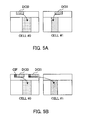
- the radio communication system it is possible to adopt a method of controlling scheduling on a per cell basis, by transmitting, from each cell, separately, downlink control information (DCI) for controlling the demodulation of each cell's downlink data (see FIG. 5A ), and a method of controlling scheduling by aggregating and transmitting downlink control information in predetermined cells (cross-carrier scheduling) (see FIG. 5B ).
- DCI downlink control information
- cross-carrier scheduling cross-carrier scheduling
- downlink control information for controlling the demodulation of the downlink data that is transmitted from each cell is transmitted from each cell using a PDCCH.
- downlink control information (DCI 0 and DCI 1) is transmitted separately, from cell #0 and cell #1, using each cell's PDCCH.
- downlink control information for controlling the downlink data that is transmitted from each cell is transmitted using the PDCCH of a predetermined cell (for example, Pcell).
- downlink control information (DCI 0 and DCI 1) for cell #0 and cell #1 is transmitted using the PDCCH of cell #0.
- a carrier indicator field for identifying the cell to which the downlink control information belongs is added to the PDCCH of the predetermined cell.
- CIF carrier indicator field
- the first radio base station apparatus 20 A and the second radio base station apparatus 20 B when transmitting downlink control information from each cell separately, separately transmit downlink control information using the PDCCH of each cell (Pcell, Scell #1, Scell #2, Scell #3 and Scell #4).
- the first radio base station apparatus 20 A and the second radio base station apparatus 20 B transmit downlink control information using the PDCCH of Pcell, instead of transmitting downlink control information from a plurality of cells (Pcell, Scell #1, Scell #2, Scell #3, Scell #4) separately.
- a CIF is attached to the PDCCH of Pcell used to transmit downlink control information.
- the first radio base station apparatus 20 A is a macro base station having a relatively large coverage area and the second radio base station apparatus 20 B is a micro base station having a relatively narrow coverage area.
- Each cell's coverage area and the number of radio base station apparatuses are by no means limited to these.
- the coverage area of the first radio base station apparatus 20 A includes the coverage area of the second radio base station apparatus 20 B, this is by no means limiting, and a configuration in which the coverage areas of the first radio base station apparatus 20 A and the second radio base station apparatus 20 B partly overlap is also possible.
- FIG. 6 provides diagrams to show examples of data transmission when dynamic cell selection to select cells dynamically is adopted in the radio communication system according to the present embodiment.
- FIG. 6A shows a case of executing cross-carrier scheduling
- FIG. 6B shows a case of transmitting downlink control information from each cell separately.
- the first radio base station apparatus 20 A transmits a downlink control signal and downlink data to the user terminal 10 using Pcell.
- the second radio base station apparatus 20 B transmits downlink data to the user terminal 10 using Scell #3. Also, downlink control information to be used to control the demodulation of that downlink data is transmitted from the first radio base station apparatus 20 A to the user terminal 10 using Pcell. In this case, a CIF to identify the cell to which the downlink control information belongs is attached to the PDCCH allocated to Pcell.
- the transmission power of the second radio base station apparatus 20 B is low compared to the first radio base station apparatus 20 A, interference from the first radio base station apparatus 20 A increases as the user terminal 10 moves farther from the second radio base station 20 B.
- the possibility that the downlink control information from the second radio base station apparatus 20 B cannot be received correctly increases.
- by transmitting downlink control information for demodulating the downlink data of the second radio base station apparatus 20 B from the cell of the first radio base station apparatus 20 A it becomes possible to correctly receive downlink control information at the user terminal 10 .
- downlink control information is transmitted from the first radio base station apparatus 20 A that performs data transmission using Pcell.
- cell-combination information is included in downlink control information and reported to user terminals (dynamic signaling), the cell-combination information is also transmitted from Pcell.
- the first radio base station apparatus 20 A transmits data to the user terminal 10 using other cells (Scell #1 and Scell #2 in FIG. 4 ) in addition to Pcell, it is possible to execute cross-carrier scheduling between Pcell and Scell #1 and Scell #2, as between Pcell and Pcell #3.
- downlink control information to control the downlink data transmitted from Scell #1 and Scell #2 is allocated to the PDCCH of Pcell, and also a CIF is attached to this PDCCH.
- FIG. 6B when downlink control information is transmitted from each cell, a downlink control signal and downlink data are transmitted to the user terminal 10 , from each cell which the first radio base station apparatus 20 A and the second radio base station apparatus 20 B use. That is to say, downlink control information to control each cell's downlink data is transmitted using each cell's PDCCH.
- FIG. 6A and FIG. 6B can also be made configurations to execute controls with various adequate changes taking into account the position of the user terminal 10 and so on.
- FIG. 7 provides diagram to show examples of data transmission when joint transmission to transmit from a plurality of cells to one UE is adopted in the radio communication system according to the present embodiment.
- FIG. 7A shows a case of executing cross-carrier scheduling
- FIG. 7B shows a case of transmitting downlink control information from each cell separately.
- downlink control information to control downlink data that is transmitted from each cell is transmitted using a predetermined cell (in FIG. 7A , Pcell of the first radio base station apparatus 20 A). That is, the first radio base station apparatus 20 A transmits a downlink control signal and downlink data to the user terminal 10 using Pcell, and the second radio base station apparatus 20 B transmits downlink data to the user terminal 10 using Scell #3.
- the downlink data that is transmitted from Scell #3 is demodulated using the downlink control information that is transmitted using the PDCCH of Pcell. Also, a CIF to identify the cell to which downlink control information belongs is attached to the PDCCH of Pcell.
- a downlink control signal and downlink data are transmitted to the user terminal 10 from each cell which the first radio base station apparatus 20 A and the second radio base station apparatus 20 B use. That is to say, downlink control information to control each cell's downlink data is transmitted using each cell's PDCCH.
- downlink data is transmitted from a plurality of transmission points to one UE (see FIG. 7 ), it is possible to transmit the same downlink data or transmit different downlink data to the user terminal 10 from different cells that perform multiple-point transmission (for example, Pcell and Scell #3).
- the method of reporting cell information in which downlink control information to be used to decode downlink data may adopt a method of including and reporting in downlink control information to the user terminal (dynamic signaling), or may adopt a method of including and reporting in higher layer signaling to the user terminal 10 (semi-static signaling).
- downlink control information is transmitted selectively from Pcell, and also information to decode data based on the downlink control information of Pcell is reported.
- downlink control information is transmitted selectively from Scell #1, and, based on the downlink control information of Scell #1, information for data decoding is reported.
- a plurality of cells which a plurality of radio base station apparatus use respectively, are aggregated, and the system band is formed with CCs that correspond to these cells. Consequently, for example, as shown in FIG. 8 , a configuration may be possible in which the first radio base station apparatus 20 A and the second radio base station apparatus 20 B each use a combination of cells that correspond to five CCs (Pcell, and Scell #1 to Scell #9).
- the number of CIF bits for identifying the cells to which downlink control information corresponds is made bigger than three bits (for example, four bits).
- the user terminals 10 and the radio base station apparatuses 20 support LTE-A.
- the radio communication system 1 is configured to include radio base station apparatuses 20 A and 20 B and a plurality of user terminals 10 A and 10 B that communicate with these radio base station apparatuses 20 A and 20 B.
- the radio base station apparatuses 20 A and 20 B are connected with a higher station apparatus 30 , and this higher station apparatus 30 is connected with a core network 40 .
- the radio base station apparatuses 20 A and 20 B are connected with each other by wire connection or by wireless connection.
- the user terminals 10 A and 10 B are able to communicate with the radio base station apparatuses 20 A and 20 B in cells C1 and C2, respectively.
- the higher station apparatus 30 includes, for example, an access gateway apparatus, a radio network controller (RNC), a mobility management entity (MME) and so on, but is by no means limited to these.
- RNC radio network controller
- MME mobility management entity
- the user terminals 10 A and 10 B may be either LTE terminals or LTE-A terminals, the following description will be given simply with respect to user terminals, unless specified otherwise.
- OFDMA Orthogonal Frequency Division Multiple Access
- SC-FDMA Single-Carrier Frequency-Division Multiple Access
- OFDMA is a multi-carrier transmission scheme to perform communication by dividing a frequency band into a plurality of narrow frequency bands (sub carriers) and mapping data to each subcarrier.
- SC-FDMA is a single carrier transmission scheme to reduce interference between terminals by dividing, per user terminal, the system band into bands formed with one or continuous resource blocks, and allowing a plurality of terminals to use mutually different bands.
- Downlink communication channels include a downlink data channel (PDSCH) that is used by user terminals 10 A and 10 B on a shared basis, and downlink L1/L2 control channels (including the PDCCH, PCFICH and PHICH). Downlink data and higher control signals are transmitted by the PDSCH. Scheduling information (downlink control information) for the PDSCH and the PUSCH and so on are transmitted by the PDCCH. The number of OFDM symbols to use for the PDCCH is transmitted by the PCFICH (Physical Control Format Indicator Channel). HARQ ACK/NACK for the PUSCH are transmitted by the PHICH (Physical Hybrid-ARQ Indicator Channel).
- PCFICH Physical Control Format Indicator Channel
- HARQ ACK/NACK for the PUSCH are transmitted by the PHICH (Physical Hybrid-ARQ Indicator Channel).
- Uplink communication channels include a PUSCH (Physical Uplink Shared CHannel), which is an uplink data channel to be used by each user terminal on a shared basis, and a PUCCH (Physical Uplink Control CHannel), which is an uplink control channel.
- PUSCH Physical Uplink Shared CHannel
- PUCCH Physical Uplink Control CHannel
- transmission data and higher control information are transmitted.
- CQI downlink channel quality information
- ACK/NACK ACK/NACK and so on are transmitted by the PUCCH.
- radio base station apparatuses 20 A and 20 B have the same configuration and therefore hereinafter will be described simply as “radio base station apparatus 20 .”
- user terminals 10 A and 10 B have the same configuration and therefore hereinafter will be described simply as “user terminal 10 .”
- the radio base station apparatus 20 has a plurality of transmitting/receiving antennas 201 , amplifying sections 202 , transmitting/receiving sections 203 , a baseband signal processing section 204 , a call processing section 205 and a transmission path interface 206 .
- Transmission data to be transmitted from the radio base station apparatus 20 to the user terminal 10 on the downlink is input from the higher station apparatus 30 , into the baseband signal processing section 204 , via the transmission path interface 206 .
- a downlink data channel signal is subjected to a PDCP layer process, division and coupling of transmission data, RLC (Radio Link Control) layer transmission processes such as an RLC retransmission control transmission process, MAC (Medium Access Control) retransmission control, including, for example, an HARQ transmission process, scheduling, transport format selection, channel coding, an inverse fast Fourier transform (IFFT) process, and a precoding process.
- RLC Radio Link Control
- MAC Medium Access Control
- HARQ transmission process scheduling, transport format selection, channel coding, an inverse fast Fourier transform (IFFT) process
- IFFT inverse fast Fourier transform
- the baseband signal processing section 204 reports control information for allowing each user terminal 10 to perform radio communication with the radio base station apparatus 20 , to the user terminals 10 connected to the same cell, by a broadcast channel.
- Information for communication in the cell includes, for example, the uplink or downlink system bandwidth, identification information of a root sequence (root sequence index) for generating random access preamble signals in the PRACH, and so on.
- the transmitting/receiving sections 203 convert baseband signals, which are subjected to precoding and output from the baseband signal processing section 204 on a per antenna basis, into a radio frequency band.
- the amplifying sections 202 amplify the radio frequency signals subjected to frequency conversion, and output the results through the transmitting/receiving antennas 201 .
- the transmitting/receiving sections 203 each constitute a receiving section that receives CoMP candidate cell information, and a transmission control section that transmits transmission power information, CoMP cell information, neighboring cell information, and that also executes CoMP transmission of transmission signals.
- radio frequency signals that are received in the transmitting/receiving antennas 201 are each amplified in the amplifying sections 202 , converted into baseband signals by frequency conversion in the transmitting/receiving sections 203 , and input in the baseband signal processing section 204 .
- the baseband signal processing section 204 applies, to the transmission data included in the baseband signals received as input, an FFT process, an IDFT process, error correction decoding, a MAC retransmission control receiving process, and RLC layer and PDCP layer receiving processes.
- the decoded signals are transferred to the higher station apparatus 30 through the transmission path interface 206 .
- the call processing section 205 performs call processes such as setting up and releasing communication channels, manages the state of the radio base station apparatus 20 and manages the radio resources.
- the user terminal 10 has a plurality of transmitting/receiving antennas 101 , amplifying sections 102 , transmitting/receiving sections 103 , a baseband signal processing section 104 and an application section 105 .
- radio frequency signals that are received in a plurality of transmitting/receiving antennas 101 are amplified in the amplifying sections 102 , and subjected to frequency conversion and converted into baseband signals in the transmitting/receiving sections 103 .
- These baseband signals are subjected to receiving processes such as an FFT process, error correction decoding and retransmission control, in the baseband signal processing section 104 .
- downlink user data is transferred to the application section 105 .
- the application section 105 performs processes related to higher layers above the physical layer and the MAC layer. Also, in the downlink data, broadcast information is also transferred to the application section 105 .
- uplink transmission data is input from the application section 105 into the baseband signal processing section 104 .
- the baseband signal processing section 104 performs a mapping process, a retransmission control (HARQ) transmission process, channel coding, a DFT process, and an IFFT process.
- a baseband signal that is output from the baseband signal processing section 104 is converted into a radio frequency band in the transmitting/receiving sections 103 , and, after that, amplified in the amplifying sections 102 and transmitted from the transmitting/receiving antennas 101 .
- HARQ retransmission control
- FIG. 13 is a functional block diagram of a baseband signal processing section 204 provided in the radio base station apparatus 20 according to the present embodiment and part of the higher layers, and primarily illustrates the function blocks for transmission processes in the baseband signal processing section 204 .
- Transmission data for user terminals 10 under the radio base station apparatus 20 is transferred from the higher station apparatus 30 to the radio base station apparatus 20 .
- FIG. 13 shows an example of the first radio base station apparatus 20 A and the second radio base station apparatus 20 B that perform data transmission by an X2 interface. Also, a case in which the first radio base station apparatus 20 A uses cells (Pcell, Scell #1 and Scell #2) that respectively correspond to three CCs, and a case in which the second radio base station apparatus 20 B uses cells (Scell #3 and Scell #4) that respectively correspond to two CCs, are shown. Obviously, the number of radio base station apparatuses 20 and the number of cells which each radio base station apparatus uses are not limited to these. Also, the first radio base station apparatus 20 A and the second radio base station apparatus 20 B may have the same configuration.
- a control information generating section 300 generates higher control information to report to user terminals by higher layer signaling, in user terminal units.
- information about the combinations of cells for example, Pcell and Scell #3, and/or Scell #1 and Scell #4
- the cell-combination information is generated in the control information generating section 300 .
- downlink control information is transmitted from one of different cells that transmit the same downlink data, if the cell information in which that downlink control information is allocated is reported to user terminals using higher layer signaling, that information is generated in the control information generating section 300 .
- the data generating section 301 outputs transmission data transferred from the higher station apparatus 30 as user data, on a per user terminal basis, separately.
- the component carrier selection section 302 selects component carriers to be used for radio communication with the user terminals 10 , on a per user basis. An increase/decrease of component carriers is reported from the radio base station apparatus 20 to the user terminals 10 by higher layer signaling, and a message of completion of application is received from the user terminals 10 .
- the scheduling section 310 controls the allocation of component carriers to the user terminals 10 under control, according to the overall communication quality of the system band. Also, the scheduling section 310 schedules LTE terminal users and LTE-A terminal users separately. The scheduling section 310 receives as input the transmission data and retransmission commands from the higher station apparatus 30 , and also receives as input the channel estimation values and resource block CQIs from the receiving section having measured uplink signals.
- the scheduling section 310 schedules the downlink control channel signal and downlink shared channel signal, with reference to the retransmission commands, channel estimation values and CQIs that are received as input.
- a propagation path in radio communication varies differently per frequency, due to frequency selective fading. So, the scheduling section 310 designates resource blocks (mapping positions) of good communication quality, on a per subframe basis, with respect to the downlink data for each user terminal 10 (which is referred to as “adaptive frequency scheduling”). In adaptive frequency scheduling, a user terminal 10 of good propagation path quality is selected for each resource block. Consequently, the scheduling section 310 designates resource blocks (mapping positions), using the CQI of each resource block, fed back from each user terminal 10 .
- the scheduling section 310 designates resource blocks (mapping positions) of good communication quality, on a per subframe basis, with respect to control information that is transmitted by the PDCCH and so on, by adaptive frequency scheduling. Consequently, the scheduling section 310 designates the resource blocks (mapping positions) using the CQI of each resource block, fed back from each user terminal 10 . Also, the MCS (coding rate and modulation scheme) that fulfills a predetermined block error rate with the allocated resource blocks is determined. Parameters that satisfy the MCS (coding rate and modulation scheme) determined by the scheduling section 310 are set in channel coding sections 303 and 308 , and modulation sections 304 and 309 .
- the baseband signal processing section 204 has channel coding sections 303 , modulation sections 304 , and a mapping section 305 to match the maximum number of users to be multiplexed, N, in one component carrier.
- the channel coding sections 303 perform channel coding of the shared data channel (PDSCH), formed with downlink data (including part of higher control signals) that is output from the data generating section 301 , on a per user basis.
- the modulation sections 304 modulate user data having been subjected to channel coding, on a per user basis.
- the mapping section 305 maps the modulated user data to radio resources.
- the baseband signal processing section 204 has a downlink control information generating section 306 that generates downlink control information, channel coding sections 308 and modulation sections 309 .
- a downlink control information generating section 306 that generates downlink control information, channel coding sections 308 and modulation sections 309 .
- an uplink shared data channel control information generating section 306 b generates uplink scheduling grants (UL Grants) for controlling the uplink data channel (PUSCH).
- the uplink scheduling grants are generated on a per user basis.
- a downlink shared data channel control information generating section 306 c generates downlink scheduling assignments (DL assignments) for controlling the downlink data channel (PDSCH). The downlink scheduling assignments are generated on a per user basis. Also, a shared channel control information generating section 306 a generates shared control channel control information, which is downlink control information that is common between users.
- the cell-combination information is generated in the downlink control information generating section 306 .
- the cell-combination information is generated in the downlink shared data channel control information generating section 306 c .
- the cell-combination information is generated in the uplink shared data channel control information generating section 306 b.
- the cell information in which the downlink control information is allocated is included in the downlink control information and transmitted to user terminals, that information is generated in the downlink control information generating section 306 .
- Control information that is modulated on a per user basis in the modulation sections 309 is multiplexed in the control channel multiplexing section 314 and furthermore interleaved in an interleaving section 315 .
- a control signal that is output from the interleaving section 315 and user data that is output from the mapping section 305 are input in an IFFT section 316 as a downlink channel signal.
- a downlink reference signal is input in the IFFT section 316 .
- the IFFT section 316 converts the downlink channel signal and the downlink reference signal from a frequency domain signal into time sequence signals by performing an inverse fast Fourier transform.
- a cyclic prefix insertion section 317 inserts cyclic prefixes in the time sequence signal of the downlink channel signal. Note that a cyclic prefix functions as a guard interval for cancelling the differences in multipath propagation delay.
- the transmission data, to which cyclic prefixes have been added, is transmitted to the transmitting/receiving sections
- FIG. 13 shows the configuration shown in above FIG. 2B (autonomous distributed control based on an independent base station configuration) as the first radio base station apparatus 20 A and the second radio base station apparatus 20 B
- the configuration shown in above FIG. 2A centralized control based on remote radio equipment configuration
- the first radio base station apparatus 20 A be a radio base station apparatus eNB
- the second radio base station apparatus 20 B be remote radio equipment (RRE).
- RRE remote radio equipment
- FIG. 14 is a functional block diagram of a baseband signal processing section 104 provided in a user terminal 10 , illustrating function blocks of an LTE-A terminal which supports LTE-A.
- a downlink signal that is received as received data from the radio base station apparatus 20 has the CPs removed in a CP removing section 401 .
- the downlink signal, from which the CPs have been removed, is input in an FFT section 402 .
- the FFT section 402 performs a fast Fourier transform (FFT) on the downlink signal, converts the time domain signal into a frequency domain signal and inputs this signal in a demapping section 403 .
- the demapping section 403 demaps the downlink signal, and extracts, from the downlink signal, multiplex control information in which a plurality of pieces of control information are multiplexed, user data and higher control signals.
- FFT fast Fourier transform
- the demapping process by the demapping section 403 is performed based on higher control signals that are received as input from the application section 105 .
- the multiplex control information output from the demapping section 403 is deinterleaved in a deinterleaving section 404 .
- the baseband signal processing section 104 has a downlink control information demodulation section 405 that demodulates downlink control information, a data demodulation section 406 that demodulates downlink shared data, and a channel estimation section 407 .
- the downlink control information demodulation section 405 has a shared channel control information demodulation section 405 a that demodulates downlink shared control channel control information from multiplex control information, an uplink shared data channel control information demodulation section 405 b that demodulates uplink shared data channel control information from multiplex control information, and a downlink shared data channel control information demodulation section 405 c that demodulates downlink shared data channel control information from multiplex control information.
- the shared channel control information demodulation section 405 a extracts shared control channel control information, which is control information that is common between users, by the blind decoding process, demodulation process, channel decoding process and so on of the common search space of the downlink control channel (PDCCH).
- the shared control channel control information includes downlink channel quality information (CQI), and therefore is input in a mapping section 415 and mapped as part of transmission data for the radio base station apparatus 20 .
- CQI downlink channel quality information
- the uplink shared data channel control information demodulation section 405 b extracts uplink shared data channel control information (for example, the UL grant) by the blind decoding process, demodulation process, channel decoding process and so on of the user-specific search space of the downlink control channel (PDCCH).
- the demodulated uplink shared data channel control information is input in the mapping section 415 and is used to control the uplink shared data channel (PUSCH).
- the downlink shared data channel control information demodulation section 405 c extracts user-specific downlink shared data channel control information (for example, DL assignment) by the blind decoding process, demodulation process, channel decoding process and so on of the user-specific search space of the downlink control channel (PDCCH).
- the demodulated downlink shared data channel control information is input in the data demodulation section 406 , is used to control the downlink shared data channel (PDSCH), and is input in the downlink shared data demodulation section 406 a.
- the downlink control information demodulation section 405 when information about the combinations of cells that perform coordinated multiple-point transmission is included in downlink control information and reported to user terminals (dynamic signaling), the downlink control information demodulation section 405 functions as a determining section to demodulate downlink control information and determine the combinations of cells to perform coordinated multiple-point transmission.
- the downlink control information demodulation section 405 when transmitting downlink control information from one of different cells that transmit the same downlink data, if the cell information in which the downlink control information is allocated is included in the downlink control information and transmitted to user terminals, the downlink control information demodulation section 405 functions as a determining section to demodulate the received downlink control information and determine the cell where the downlink control signal to use to demodulate the downlink data is allocated.
- these pieces of information are demodulated in the downlink shared data channel control information demodulation section 405 c , and, when these pieces of information are included in a UL grant, these pieces of information are demodulated in the uplink shared data channel control information demodulation section 405 b.
- the data demodulation section 406 includes a downlink shared data demodulation section 406 a that demodulates user data and higher control signals, and a downlink shared channel data demodulation section 406 b that demodulates downlink shared channel data.
- the downlink shared data demodulation section 406 a acquires the user data, higher control information and so on, based on the downlink shared data channel control information that is received as input from the downlink shared data channel control information demodulation section 405 c .
- the downlink shared channel data demodulation section 406 b demodulates the downlink shared channel data based on the uplink shared data channel control information that is received as input from the uplink shared data channel control information demodulation section 405 b.
- the downlink shared data demodulation section 406 a functions as a determining section to determine the combinations of cells to perform coordinated multiple-point transmission.
- the downlink shared data demodulation section 406 a when transmitting downlink control information from one of different cells that transmit the same downlink data, if the cell information in which the downlink control information is allocated is reported to user terminals using higher layer signaling, the downlink shared data demodulation section 406 a functions as a determining section to determine the cell where the downlink control signal to use to demodulate the downlink data is allocated.
- the channel estimation section 407 performs channel estimation using user-specific reference signals (DM-RSs) or cell-specific reference signals (CRSs).
- DM-RSs user-specific reference signals
- CRSs cell-specific reference signals
- the estimated channel variation is output to the shared channel control information demodulation section 405 a , the uplink shared data channel control information demodulation section 405 b , the downlink shared data channel control information demodulation section 405 c and the downlink shared data demodulation section 406 a .
- the demodulation process is performed using the estimated channel variation and the reference signals for demodulation.
- the baseband signal processing section 104 has, as function blocks of the transmission processing system, a data generating section 411 , a channel coding section 412 , a modulation section 413 , a DFT section 414 , a mapping section 415 , an IFFT section 416 and a CP insertion section 417 .
- the data generating section 411 generates transmission data from bit data that is received as input from the application section 105 .
- the channel coding section 412 applies channel coding processes such as error correction to transmission data, and the modulation section 413 modulates the transmission data after channel coding by QPSK and so on.
- the DFT section 414 performs a discrete Fourier transform on the modulated transmission data.
- the mapping section 415 maps the frequency components of the data symbol after the DFT to subcarrier positions designated by the radio base station apparatus 20 .
- the IFFT section 416 converts the input data to match the system band into time to sequence data by performing an inverse fast Fourier transform, and the CP insertion section 417 inserts cyclic prefixes in the time sequence data per data division.
Landscapes
- Engineering & Computer Science (AREA)
- Signal Processing (AREA)
- Computer Networks & Wireless Communication (AREA)
- Mobile Radio Communication Systems (AREA)
Applications Claiming Priority (3)
| Application Number | Priority Date | Filing Date | Title |
|---|---|---|---|
| JP2011167567 | 2011-07-29 | ||
| JP2011-167567 | 2011-07-29 | ||
| PCT/JP2012/068925 WO2013018639A1 (ja) | 2011-07-29 | 2012-07-26 | 無線通信システム、無線通信方法、無線基地局装置及びユーザ端末 |
Publications (2)
| Publication Number | Publication Date |
|---|---|
| US20140140316A1 US20140140316A1 (en) | 2014-05-22 |
| US9313014B2 true US9313014B2 (en) | 2016-04-12 |
Family
ID=47629164
Family Applications (1)
| Application Number | Title | Priority Date | Filing Date |
|---|---|---|---|
| US14/234,438 Active 2033-01-06 US9313014B2 (en) | 2011-07-29 | 2012-07-26 | Radio communication system, radio communication method, radio base station apparatus and user terminal |
Country Status (5)
| Country | Link |
|---|---|
| US (1) | US9313014B2 (ja) |
| EP (1) | EP2739083A4 (ja) |
| JP (1) | JP5612770B2 (ja) |
| CN (2) | CN103718599A (ja) |
| WO (1) | WO2013018639A1 (ja) |
Families Citing this family (10)
| Publication number | Priority date | Publication date | Assignee | Title |
|---|---|---|---|---|
| CN107104776B (zh) | 2011-09-30 | 2021-02-12 | 三星电子株式会社 | 用于发送和接收数据的方法、接收器和发送器 |
| JP6251292B2 (ja) * | 2013-03-27 | 2017-12-20 | エルジー エレクトロニクス インコーポレイティド | 無線通信システムにおいて干渉除去のための方法及びそのための装置 |
| CN105122676B (zh) * | 2013-04-05 | 2018-07-03 | Lg电子株式会社 | 在无线接入系统中发送上行链路控制信息的方法及其设备 |
| WO2015061987A1 (en) * | 2013-10-30 | 2015-05-07 | Qualcomm Incorporated | Cross-carrier indication of uplink/downlink subframe configurations |
| US9531512B2 (en) * | 2013-11-25 | 2016-12-27 | Qualcomm Incorporated | Techniques for downlink coordinated multi-point (CoMP) communications using unlicensed radio frequency spectrum band |
| US9729283B2 (en) * | 2014-05-08 | 2017-08-08 | Intel IP Corporation | Systems, methods and devices for flexible retransmissions |
| WO2016114561A1 (ko) * | 2015-01-12 | 2016-07-21 | 엘지전자 주식회사 | 무선 통신 시스템에서 단말의 동작 방법 및 장치 |
| CN107211419B (zh) * | 2015-01-29 | 2021-06-01 | 株式会社Ntt都科摩 | 用户终端、无线基站及无线通信方法 |
| CN109076584B (zh) | 2016-06-29 | 2021-05-18 | 华为技术有限公司 | 通信方法、装置和系统 |
| WO2018127145A1 (zh) | 2017-01-06 | 2018-07-12 | 华为技术有限公司 | 通信方法、装置和系统 |
Citations (11)
| Publication number | Priority date | Publication date | Assignee | Title |
|---|---|---|---|---|
| US20110170496A1 (en) * | 2010-01-11 | 2011-07-14 | Research In Motion Limited | Control Channel Interference Management and Extended PDCCH for Heterogeneous Network |
| US20110312328A1 (en) * | 2010-06-18 | 2011-12-22 | Infineon Technologies Ag | Communication terminal, communication device, method for data communication, and method for frequency allocation |
| US20120063321A1 (en) * | 2010-03-17 | 2012-03-15 | Texas Instruments Incorporated | CFI Signaling for Heterogeneous Networks with Multiple Component Carriers in LTE-Advanced |
| US20120230272A1 (en) * | 2011-03-11 | 2012-09-13 | Samsung Electronics Co., Ltd. | Harq method and apparatus for communication system |
| US8280389B1 (en) * | 2011-04-12 | 2012-10-02 | Renesas Mobile Corporation | Sensing configuration in carrier aggregation scenarios |
| US20130051355A1 (en) * | 2010-05-03 | 2013-02-28 | Pantech Co., Ltd. | Apparatus and method for transmitting control information in a multi-component carrier system |
| US20130058245A1 (en) * | 2010-04-12 | 2013-03-07 | Samsung Electronics Co. Ltd. | Handover with carrier aggregation |
| US20130094456A1 (en) * | 2010-04-06 | 2013-04-18 | Nec Corporation | Method of configuring cross-carrier cfi |
| US20130201930A1 (en) * | 2010-04-28 | 2013-08-08 | Kyocera Corporation | Radio communication system, radio base station, radio terminal, and radio communication method |
| US8780833B2 (en) * | 2009-02-23 | 2014-07-15 | Lg Electronics Inc. | Control channel monitoring apparatus in multi-carrier system and method thereof |
| US8843168B2 (en) * | 2010-05-03 | 2014-09-23 | Intel Corporation | Allocating a control channel for carrier aggregation |
Family Cites Families (2)
| Publication number | Priority date | Publication date | Assignee | Title |
|---|---|---|---|---|
| CN101873671B (zh) * | 2009-04-23 | 2012-10-03 | 电信科学技术研究院 | 一种确定参与CoMP的小区的方法、系统和装置 |
| US9014138B2 (en) * | 2009-08-07 | 2015-04-21 | Blackberry Limited | System and method for a virtual carrier for multi-carrier and coordinated multi-point network operation |
-
2012
- 2012-07-26 EP EP12819953.6A patent/EP2739083A4/en not_active Withdrawn
- 2012-07-26 CN CN201280038267.9A patent/CN103718599A/zh active Pending
- 2012-07-26 CN CN201710367432.XA patent/CN107196729B/zh active Active
- 2012-07-26 JP JP2013526854A patent/JP5612770B2/ja active Active
- 2012-07-26 WO PCT/JP2012/068925 patent/WO2013018639A1/ja active Application Filing
- 2012-07-26 US US14/234,438 patent/US9313014B2/en active Active
Patent Citations (11)
| Publication number | Priority date | Publication date | Assignee | Title |
|---|---|---|---|---|
| US8780833B2 (en) * | 2009-02-23 | 2014-07-15 | Lg Electronics Inc. | Control channel monitoring apparatus in multi-carrier system and method thereof |
| US20110170496A1 (en) * | 2010-01-11 | 2011-07-14 | Research In Motion Limited | Control Channel Interference Management and Extended PDCCH for Heterogeneous Network |
| US20120063321A1 (en) * | 2010-03-17 | 2012-03-15 | Texas Instruments Incorporated | CFI Signaling for Heterogeneous Networks with Multiple Component Carriers in LTE-Advanced |
| US20130094456A1 (en) * | 2010-04-06 | 2013-04-18 | Nec Corporation | Method of configuring cross-carrier cfi |
| US20130058245A1 (en) * | 2010-04-12 | 2013-03-07 | Samsung Electronics Co. Ltd. | Handover with carrier aggregation |
| US20130201930A1 (en) * | 2010-04-28 | 2013-08-08 | Kyocera Corporation | Radio communication system, radio base station, radio terminal, and radio communication method |
| US20130051355A1 (en) * | 2010-05-03 | 2013-02-28 | Pantech Co., Ltd. | Apparatus and method for transmitting control information in a multi-component carrier system |
| US8843168B2 (en) * | 2010-05-03 | 2014-09-23 | Intel Corporation | Allocating a control channel for carrier aggregation |
| US20110312328A1 (en) * | 2010-06-18 | 2011-12-22 | Infineon Technologies Ag | Communication terminal, communication device, method for data communication, and method for frequency allocation |
| US20120230272A1 (en) * | 2011-03-11 | 2012-09-13 | Samsung Electronics Co., Ltd. | Harq method and apparatus for communication system |
| US8280389B1 (en) * | 2011-04-12 | 2012-10-02 | Renesas Mobile Corporation | Sensing configuration in carrier aggregation scenarios |
Non-Patent Citations (5)
| Title |
|---|
| 3GPP TR 25.912 V7.1.0; "3rd Generation Partnership Project; Technical Specification Group Radio Access Network; Feasibility study for evolved Universal Terrestrial Radio Access (UTRA) and Universal Terrestrial Radio Access Network (UTRAN) (Release 7);" Sep. 2006 (57 pages). |
| Decision to Grant a Patent in corresponding Japanese application No. 2013-526854, mailed Aug. 26, 2014 (4 pages). |
| International Search Report for corresponding International Application No. PCT/JP2012/068925, mailed Sep. 4, 2012 (1 page). |
| Nokia Siemens Networks et al.; "Cell aggregation: A unified approach to CoMP and carrier aggregation;" 3GPP TSG-RAN WG1 Meeting #65, R1-111737; Barcelona, Spain; May 9-13, 2011 (3 pages). |
| Office Action in counterpart Japanese Patent Application No. 2013-526854, mailed Jun. 10, 2014 (3 pages). |
Also Published As
| Publication number | Publication date |
|---|---|
| JPWO2013018639A1 (ja) | 2015-03-05 |
| EP2739083A1 (en) | 2014-06-04 |
| CN103718599A (zh) | 2014-04-09 |
| CN107196729A (zh) | 2017-09-22 |
| US20140140316A1 (en) | 2014-05-22 |
| CN107196729B (zh) | 2019-05-28 |
| JP5612770B2 (ja) | 2014-10-22 |
| WO2013018639A1 (ja) | 2013-02-07 |
| EP2739083A4 (en) | 2015-04-08 |
Similar Documents
| Publication | Publication Date | Title |
|---|---|---|
| US9756633B2 (en) | Radio base station apparatus, mobile terminal apparatus, radio communication system and radio communication method | |
| US9634808B2 (en) | Radio communication system, radio communication method, user terminal and radio base station | |
| US9380570B2 (en) | Radio base station apparatus, user terminal, radio communication system and radio communication method | |
| US9979454B2 (en) | Radio communication system and method for feeding back a plurality of pieces of channel state information under coordinated multi-point transmission | |
| US9313014B2 (en) | Radio communication system, radio communication method, radio base station apparatus and user terminal | |
| US9742534B2 (en) | Radio communication method, radio communication system, radio base station and user terminal | |
| US20140133418A1 (en) | Channel state information reporting method, radio base station apparatus, user terminal and radio communication system | |
| US9801159B2 (en) | Base station apparatus, mobile terminal apparatus and communication control method | |
| US9467989B2 (en) | Base station apparatus, mobile terminal apparatus, communication system and communication method | |
| EP2849496A1 (en) | Wireless communication system, wireless base station device, user terminal and communication control method | |
| US9439181B2 (en) | Radio communication system, radio base station apparatus, user terminal, and radio communication method | |
| US9439182B2 (en) | Radio communication system, radio base station apparatus, user terminal and radio communication method | |
| US20140192758A1 (en) | Communication system, base station apparatus, mobile terminal apparatus and communication method | |
| US9337975B2 (en) | Radio communication system, radio communication method, radio base station apparatus and user terminal | |
| US20150071200A1 (en) | Communication system, base station apparatus and communication method | |
| US20170237473A1 (en) | Radio communication system, radio base station apparatus and retransmission control method |
Legal Events
| Date | Code | Title | Description |
|---|---|---|---|
| AS | Assignment |
Owner name: NTT DOCOMO, INC., JAPAN Free format text: ASSIGNMENT OF ASSIGNORS INTEREST;ASSIGNORS:NAGATA, SATOSHI;ABE, TETSUSHI;KISHIYAMA, YOSHIHISA;AND OTHERS;REEL/FRAME:032121/0606 Effective date: 20131226 |
|
| STCF | Information on status: patent grant |
Free format text: PATENTED CASE |
|
| MAFP | Maintenance fee payment |
Free format text: PAYMENT OF MAINTENANCE FEE, 4TH YEAR, LARGE ENTITY (ORIGINAL EVENT CODE: M1551); ENTITY STATUS OF PATENT OWNER: LARGE ENTITY Year of fee payment: 4 |
|
| MAFP | Maintenance fee payment |
Free format text: PAYMENT OF MAINTENANCE FEE, 8TH YEAR, LARGE ENTITY (ORIGINAL EVENT CODE: M1552); ENTITY STATUS OF PATENT OWNER: LARGE ENTITY Year of fee payment: 8 |