US9296293B1 - Vehicle load management structure - Google Patents

Vehicle load management structure Download PDF

Info

Publication number
US9296293B1
US9296293B1 US14/547,834 US201414547834A US9296293B1 US 9296293 B1 US9296293 B1 US 9296293B1 US 201414547834 A US201414547834 A US 201414547834A US 9296293 B1 US9296293 B1 US 9296293B1
Authority
US
United States
Prior art keywords
elongate
cross
members
vehicle
fuel tank
Prior art date
Legal status (The legal status is an assumption and is not a legal conclusion. Google has not performed a legal analysis and makes no representation as to the accuracy of the status listed.)
Expired - Fee Related, expires
Application number
US14/547,834
Inventor
Mohamed Ridha Baccouche
Rahul Arora
Horst Heribert Lanzerath
Carsten Tragsdorf
Current Assignee (The listed assignees may be inaccurate. Google has not performed a legal analysis and makes no representation or warranty as to the accuracy of the list.)
Ford Global Technologies LLC
Original Assignee
Ford Global Technologies LLC
Priority date (The priority date is an assumption and is not a legal conclusion. Google has not performed a legal analysis and makes no representation as to the accuracy of the date listed.)
Filing date
Publication date
Application filed by Ford Global Technologies LLC filed Critical Ford Global Technologies LLC
Priority to US14/547,834 priority Critical patent/US9296293B1/en
Assigned to FORD GLOBAL TECHNOLOGIES, LLC reassignment FORD GLOBAL TECHNOLOGIES, LLC ASSIGNMENT OF ASSIGNORS INTEREST (SEE DOCUMENT FOR DETAILS). Assignors: ARORA, RAHUL, BACCOUCHE, MOHAMED RIDHA, LANZERATH, HORST HERIBERT, TRAGSDORF, CARSTEN
Priority to DE102015221820.1A priority patent/DE102015221820A1/en
Priority to RU2015148168A priority patent/RU2692023C2/en
Priority to MX2015015884A priority patent/MX374135B/en
Priority to CN201510799554.7A priority patent/CN105599812A/en
Application granted granted Critical
Publication of US9296293B1 publication Critical patent/US9296293B1/en
Expired - Fee Related legal-status Critical Current
Adjusted expiration legal-status Critical

Links

Images

Classifications

    • BPERFORMING OPERATIONS; TRANSPORTING
    • B62LAND VEHICLES FOR TRAVELLING OTHERWISE THAN ON RAILS
    • B62DMOTOR VEHICLES; TRAILERS
    • B62D21/00Understructures, i.e. chassis frame on which a vehicle body may be mounted
    • B62D21/09Means for mounting load bearing surfaces
    • BPERFORMING OPERATIONS; TRANSPORTING
    • B62LAND VEHICLES FOR TRAVELLING OTHERWISE THAN ON RAILS
    • B62DMOTOR VEHICLES; TRAILERS
    • B62D25/00Superstructure or monocoque structure sub-units; Parts or details thereof not otherwise provided for
    • BPERFORMING OPERATIONS; TRANSPORTING
    • B60VEHICLES IN GENERAL
    • B60KARRANGEMENT OR MOUNTING OF PROPULSION UNITS OR OF TRANSMISSIONS IN VEHICLES; ARRANGEMENT OR MOUNTING OF PLURAL DIVERSE PRIME-MOVERS IN VEHICLES; AUXILIARY DRIVES FOR VEHICLES; INSTRUMENTATION OR DASHBOARDS FOR VEHICLES; ARRANGEMENTS IN CONNECTION WITH COOLING, AIR INTAKE, GAS EXHAUST OR FUEL SUPPLY OF PROPULSION UNITS IN VEHICLES
    • B60K15/00Arrangement in connection with fuel supply of combustion engines or other fuel consuming energy converters, e.g. fuel cells; Mounting or construction of fuel tanks
    • B60K15/03Fuel tanks
    • B60K15/063Arrangement of tanks
    • B60K15/067Mounting of tanks
    • B60K15/07Mounting of tanks of gas tanks
    • BPERFORMING OPERATIONS; TRANSPORTING
    • B60VEHICLES IN GENERAL
    • B60KARRANGEMENT OR MOUNTING OF PROPULSION UNITS OR OF TRANSMISSIONS IN VEHICLES; ARRANGEMENT OR MOUNTING OF PLURAL DIVERSE PRIME-MOVERS IN VEHICLES; AUXILIARY DRIVES FOR VEHICLES; INSTRUMENTATION OR DASHBOARDS FOR VEHICLES; ARRANGEMENTS IN CONNECTION WITH COOLING, AIR INTAKE, GAS EXHAUST OR FUEL SUPPLY OF PROPULSION UNITS IN VEHICLES
    • B60K15/00Arrangement in connection with fuel supply of combustion engines or other fuel consuming energy converters, e.g. fuel cells; Mounting or construction of fuel tanks
    • B60K15/03Fuel tanks
    • B60K15/063Arrangement of tanks
    • B60K15/067Mounting of tanks
    • BPERFORMING OPERATIONS; TRANSPORTING
    • B62LAND VEHICLES FOR TRAVELLING OTHERWISE THAN ON RAILS
    • B62DMOTOR VEHICLES; TRAILERS
    • B62D25/00Superstructure or monocoque structure sub-units; Parts or details thereof not otherwise provided for
    • B62D25/20Floors or bottom sub-units
    • BPERFORMING OPERATIONS; TRANSPORTING
    • B62LAND VEHICLES FOR TRAVELLING OTHERWISE THAN ON RAILS
    • B62DMOTOR VEHICLES; TRAILERS
    • B62D25/00Superstructure or monocoque structure sub-units; Parts or details thereof not otherwise provided for
    • B62D25/20Floors or bottom sub-units
    • B62D25/2009Floors or bottom sub-units in connection with other superstructure subunits
    • B62D25/2027Floors or bottom sub-units in connection with other superstructure subunits the subunits being rear structures
    • BPERFORMING OPERATIONS; TRANSPORTING
    • B60VEHICLES IN GENERAL
    • B60KARRANGEMENT OR MOUNTING OF PROPULSION UNITS OR OF TRANSMISSIONS IN VEHICLES; ARRANGEMENT OR MOUNTING OF PLURAL DIVERSE PRIME-MOVERS IN VEHICLES; AUXILIARY DRIVES FOR VEHICLES; INSTRUMENTATION OR DASHBOARDS FOR VEHICLES; ARRANGEMENTS IN CONNECTION WITH COOLING, AIR INTAKE, GAS EXHAUST OR FUEL SUPPLY OF PROPULSION UNITS IN VEHICLES
    • B60K15/00Arrangement in connection with fuel supply of combustion engines or other fuel consuming energy converters, e.g. fuel cells; Mounting or construction of fuel tanks
    • B60K15/03Fuel tanks
    • B60K15/063Arrangement of tanks
    • B60K2015/0634Arrangement of tanks the fuel tank is arranged below the vehicle floor
    • BPERFORMING OPERATIONS; TRANSPORTING
    • B60VEHICLES IN GENERAL
    • B60KARRANGEMENT OR MOUNTING OF PROPULSION UNITS OR OF TRANSMISSIONS IN VEHICLES; ARRANGEMENT OR MOUNTING OF PLURAL DIVERSE PRIME-MOVERS IN VEHICLES; AUXILIARY DRIVES FOR VEHICLES; INSTRUMENTATION OR DASHBOARDS FOR VEHICLES; ARRANGEMENTS IN CONNECTION WITH COOLING, AIR INTAKE, GAS EXHAUST OR FUEL SUPPLY OF PROPULSION UNITS IN VEHICLES
    • B60K15/00Arrangement in connection with fuel supply of combustion engines or other fuel consuming energy converters, e.g. fuel cells; Mounting or construction of fuel tanks
    • B60K15/03Fuel tanks
    • B60K15/063Arrangement of tanks
    • B60K2015/0638Arrangement of tanks the fuel tank is arranged in the rear of the vehicle
    • BPERFORMING OPERATIONS; TRANSPORTING
    • B60VEHICLES IN GENERAL
    • B60YINDEXING SCHEME RELATING TO ASPECTS CROSS-CUTTING VEHICLE TECHNOLOGY
    • B60Y2306/00Other features of vehicle sub-units
    • B60Y2306/01Reducing damages in case of crash, e.g. by improving battery protection

Definitions

  • the present disclosure relates to vehicle body structures.
  • An emergency response vehicle may be placed under enhanced loads in comparison to standard vehicles. Energy associated with the loads may be absorbed by managing structural deflection. The amount of space available for deflection of the structure may influence required stiffness values for relevant vehicle load bearing structures. In vehicle environments having components in an efficient package space, clearance between components is minimized. Emergency response vehicles may benefit from structural countermeasures to manage non-standard loads.
  • a vehicle structure in at least one embodiment, includes a first member extending obliquely beneath an outer surface of an underbody component, and a second member extending at an acute angle to the first member.
  • the second member is arranged to form an apex near an end of the first member.
  • the vehicle structure also includes an interconnecting member connected to both the first and second members at locations offset from the apex. The first member, the second member, and the interconnecting member cooperate to enclose a portion of the underbody component.
  • a vehicle structure in at least one embodiment, includes a pair of opposing longitudinal rails extending forward from a rear bumper beam. A first cross-member connectedly spans across the rails forward of the bumper beam. Similarly, a second cross-member connectedly spans across the rails forward of the first cross-member.
  • the vehicle structure also includes a fuel tank disposed between the rails, and between the first and second cross-members.
  • the vehicle structure further includes an elongate first member connectedly extending from the first cross-member to the second cross-member at an oblique angle, and an elongate second member connectedly extending from the first cross-member at an acute angle relative to the first elongate member.
  • the elongate second member is arranged to form an apex proximate to the first cross-member.
  • the vehicle structure further includes at least one interconnecting member joining the first elongate member to the second elongate member. Collectively the elongate first and second members enclose a lower portion of the vehicle fuel tank.
  • FIG. 1 is a rear perspective view of a vehicle body.
  • FIG. 2 is a bottom view of the vehicle of FIG. 1 .
  • FIG. 3 is a bottom view of a portion of a sub-structure of the vehicle of FIG. 1 .
  • FIG. 4 is a rear perspective view of a portion of a vehicle sub-structure.
  • FIG. 5 is an exploded view of a load management truss structure.
  • a rear portion 12 of a vehicle 10 is depicted.
  • a rear bumper surface 14 covers an underlying structure, such as a bumper beam for example.
  • a fuel tank, a spare tire, as well as various other components may be disposed at a lower rear portion forward of the rear bumper.
  • a trunk storage compartment 16 near the rear portion 12 provides storage for equipment and various other cargo.
  • a passenger compartment is located forward of the trunk storage compartment 16 and above the fuel tank.
  • FIG. 2 is a bottom view of the underside of the rear portion 12 of the vehicle 10 .
  • An arrow denoted by “REAR” indicates the rear direction of the vehicle 10 .
  • the vehicle body includes an underbody structure 18 .
  • the underbody structure 18 comprises two longitudinal rear rails 20 that are laterally spaced from each other to be opposing sides of the vehicle 10 .
  • the rear rails 20 are interconnected by a series of laterally extending cross-members.
  • a rear bumper beam 22 extends laterally at a rear most portion of the vehicle 10 beneath the outer rear bumper surface 16 .
  • a first lateral cross-member 24 spans across the space between the pair of rear rails 20 at a distance forwardly spaced from the rear bumper beam 22 .
  • a second lateral cross-member 26 spans across the space between the pair of rear rails 20 at a distance forwardly spaced from the first lateral cross-member 24 .
  • An open portion is defined between each pair of the adjacent lateral members.
  • a first open portion 28 is defined between the rear bumper beam 22 and the first lateral cross-member 24 .
  • a second open portion 30 is defined between the first lateral cross-member 24 and the second lateral cross-member 26 .
  • a lower portion of the rear trunk compartment 16 extends down into the first open portion 28 between the rear bumper beam 22 and the first lateral cross-member 24 .
  • a recess 32 or “tire tub,” may be formed for example to house a vehicle spare tire below the main area of the trunk compartment. In this way, volume of the trunk storage compartment 16 may be maximized in an area above the vehicle spare tire.
  • Other components may similarly extend downwardly into the various open portions between the body sub-frame members to optimize package space.
  • a fuel tank 34 may be packaged in the second open portion 30 between the first lateral cross-member 24 and the second lateral cross-member 26 .
  • the fuel tank 34 may have an amorphous shape to take best advantage of the available space and maximize fuel tank volume.
  • an exhaust pipe 35 extends longitudinally near a center line of the vehicle body.
  • the fuel tank 34 includes two main portions, each straddled on opposing sides of the exhaust pipe 35 .
  • a first main portion 36 and a second main portion 38 each include an internal volume and together comprise an overall fuel tank volume.
  • Components are arranged having a close proximity with respect to each other to increase package efficiency, and available crush space for the vehicle structure to absorb energy during impact may be reduced. Additionally, high performance vehicles may encounter more severe loads as compared to conventional passenger vehicles. For example, law enforcement vehicles may undergo a higher intensity of loading. Also, law enforcement and other emergency response vehicles may commonly carry a large amount of equipment in the trunk storage compartment. Filling the trunk storage compartment with rigid or semi-rigid materials may further reduce the available crush space of the rear vehicle structure. Therefore additional measures may aid in managing rear crash loads through the vehicle structure.
  • the fuel tank 34 may be formed from plastic or other malleable material to allow for deformation during impact while maintaining the integrity of the internal fuel tank volume. Design limits may be set for example, to limit strain, volume, or other design criteria to enhance performance. Since the geometry of the fuel tank 34 includes the first main portion 36 and the second main portion 38 on opposing sides of the vehicle, it may be advantageous to independently shield each main portion of the fuel tank 34 .
  • a cage structure is provided to enclose at least a portion of the fuel tank.
  • each of a pair of truss structures encloses one of the main portions 36 , 38 of the fuel tank 34 .
  • a truss structure according to the present disclosure may be suitable to enclose a portion of a number of different underbody components as required.
  • the first elongate member 42 and the second elongate member 46 are arranged to form an apex 48 near an end of the members.
  • the apex 48 is proximate to a rearward end of each of the members and adjacent to the first lateral cross-member 24 .
  • the apex 48 is depicted near a rear end by way of example, it should be appreciated that the relationship between the first elongate member 42 and the second elongate member 46 may be reversed such that an acute angle between the components defines an apex near a forward end.
  • Each of the truss systems 40 further include an interconnecting member 50 joining the first elongate member 42 to the second elongate member 46 at locations offset from the apex 48 .
  • the interconnecting member 50 is attached to the first elongate member 42 and the second elongate member 46 near a middle portion. The interconnecting member 50 helps to complete a portion of a triangular truss to allow for primarily axial loading of each of the elongate members as compared to bending loads.
  • the elongate first and second members 42 , 46 may be comprised of high strength tubular elements.
  • the interconnecting member 50 may comprise a third tubular member.
  • the members may be formed from high-strength low-alloy (HSLA) steel such as HSLA 350 or HSLA 550.
  • HSLA high-strength low-alloy
  • ultra high-strength steel such as Usibor® 1500 may allow for additional weight savings through a reduction in material thickness while maintaining the overall stiffness properties of the truss structure.
  • the tubular members may employ any number of suitable cross section shapes, including various polygonal closed cross sections.
  • open cross sections such as C-beam cross sections or I-beam cross sections for example, may also provide suitable structure.
  • an arrangement of elongate members into a truss assembly may efficiently manage rear impact loads associated with a high-performance vehicle.
  • each of the elongate members may be shaped to conform to the lower shape of the fuel tank 34 .
  • the structure of the truss system 40 may include a series of bends to create an upright portion near a front end, a generally horizontal portion near a middle portion, and an upright portion near an opposing rear end of the truss structure 40 .
  • the truss structures of the present disclosure may be employed to manage severe rear impact loads associated with a high-performance vehicle. Conversely, a standard series variant of the same vehicle may not require the supplemental structure, as it generally experiences less severe loads.
  • the truss system 40 is provided as a structural enhancement bolt-on upgrade to a standard series variant.
  • bolted attachment may be employed at the terminal ends of the elongate members.
  • Rearward bolted attachments 52 may be secured to the first lateral cross-member 24 aft of the fuel tank 34 .
  • forward bolted attachments 54 may be secured to the second lateral cross-member 26 on the forward side of the fuel tank 34 . In this way, a truss structure according to the present disclosure may be selectively equipped on a vehicle without the need for expensive fixtures and tooling.

Landscapes

  • Engineering & Computer Science (AREA)
  • Chemical & Material Sciences (AREA)
  • Combustion & Propulsion (AREA)
  • Transportation (AREA)
  • Mechanical Engineering (AREA)
  • Life Sciences & Earth Sciences (AREA)
  • Sustainable Development (AREA)
  • Sustainable Energy (AREA)
  • Body Structure For Vehicles (AREA)
  • Cooling, Air Intake And Gas Exhaust, And Fuel Tank Arrangements In Propulsion Units (AREA)

Abstract

A vehicle structure includes a first member extending obliquely beneath an outer surface of an underbody component, and a second member extending at an acute angle to the first member. The second member is arranged to form an apex near an end of the first member. The vehicle structure also includes an interconnecting member connected to both the first and second members at locations offset from the apex. The first member, the second member, and the interconnecting member cooperate to enclose a portion of the underbody component.

Description

TECHNICAL FIELD
The present disclosure relates to vehicle body structures.
BACKGROUND
An emergency response vehicle may be placed under enhanced loads in comparison to standard vehicles. Energy associated with the loads may be absorbed by managing structural deflection. The amount of space available for deflection of the structure may influence required stiffness values for relevant vehicle load bearing structures. In vehicle environments having components in an efficient package space, clearance between components is minimized. Emergency response vehicles may benefit from structural countermeasures to manage non-standard loads.
SUMMARY
In at least one embodiment, a vehicle structure includes a first member extending obliquely beneath an outer surface of an underbody component, and a second member extending at an acute angle to the first member. The second member is arranged to form an apex near an end of the first member. The vehicle structure also includes an interconnecting member connected to both the first and second members at locations offset from the apex. The first member, the second member, and the interconnecting member cooperate to enclose a portion of the underbody component.
In at least one embodiment, a vehicle structure includes a pair of opposing longitudinal rails extending forward from a rear bumper beam. A first cross-member connectedly spans across the rails forward of the bumper beam. Similarly, a second cross-member connectedly spans across the rails forward of the first cross-member. The vehicle structure also includes a fuel tank disposed between the rails, and between the first and second cross-members. The vehicle structure further includes an elongate first member connectedly extending from the first cross-member to the second cross-member at an oblique angle, and an elongate second member connectedly extending from the first cross-member at an acute angle relative to the first elongate member. The elongate second member is arranged to form an apex proximate to the first cross-member. The vehicle structure further includes at least one interconnecting member joining the first elongate member to the second elongate member. Collectively the elongate first and second members enclose a lower portion of the vehicle fuel tank.
In at least one embodiment, a vehicle load management system includes an underbody frame having a pair of longitudinal rails connected by laterally extending cross-members. The vehicle load management system also includes a fuel tank disposed between the pair of longitudinal rails and between two adjacent laterally extending cross-members. A pair of truss structures connectedly spans the underbody frame beneath a portion of the fuel tank to carry load.
BRIEF DESCRIPTION OF THE DRAWINGS
FIG. 1 is a rear perspective view of a vehicle body.
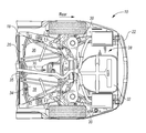
FIG. 2 is a bottom view of the vehicle of FIG. 1.
FIG. 3 is a bottom view of a portion of a sub-structure of the vehicle of FIG. 1.
FIG. 4 is a rear perspective view of a portion of a vehicle sub-structure.
FIG. 5 is an exploded view of a load management truss structure.
DETAILED DESCRIPTION
As required, detailed embodiments of the present invention are disclosed herein; however, it is to be understood that the disclosed embodiments are merely exemplary of the invention that may be embodied in various and alternative forms. The figures are not necessarily to scale; some features may be exaggerated or minimized to show details of particular components. Therefore, specific structural and functional details disclosed herein are not to be interpreted as limiting, but merely as a representative basis for teaching one skilled in the art to variously employ the present invention.
Referring to FIG. 1, a rear portion 12 of a vehicle 10 is depicted. A rear bumper surface 14 covers an underlying structure, such as a bumper beam for example. A fuel tank, a spare tire, as well as various other components may be disposed at a lower rear portion forward of the rear bumper. A trunk storage compartment 16 near the rear portion 12 provides storage for equipment and various other cargo. In at least one embodiment, a passenger compartment is located forward of the trunk storage compartment 16 and above the fuel tank.
FIG. 2 is a bottom view of the underside of the rear portion 12 of the vehicle 10. An arrow denoted by “REAR” indicates the rear direction of the vehicle 10. The vehicle body includes an underbody structure 18. The underbody structure 18 comprises two longitudinal rear rails 20 that are laterally spaced from each other to be opposing sides of the vehicle 10. The rear rails 20 are interconnected by a series of laterally extending cross-members. A rear bumper beam 22 extends laterally at a rear most portion of the vehicle 10 beneath the outer rear bumper surface 16. A first lateral cross-member 24 spans across the space between the pair of rear rails 20 at a distance forwardly spaced from the rear bumper beam 22. A second lateral cross-member 26 spans across the space between the pair of rear rails 20 at a distance forwardly spaced from the first lateral cross-member 24. An open portion is defined between each pair of the adjacent lateral members. A first open portion 28 is defined between the rear bumper beam 22 and the first lateral cross-member 24. A second open portion 30 is defined between the first lateral cross-member 24 and the second lateral cross-member 26. Certain vehicle components are recessed downward and packaged within the open portions to optimize package utilization in the vertical direction.
In at least one embodiment, a lower portion of the rear trunk compartment 16 extends down into the first open portion 28 between the rear bumper beam 22 and the first lateral cross-member 24. A recess 32, or “tire tub,” may be formed for example to house a vehicle spare tire below the main area of the trunk compartment. In this way, volume of the trunk storage compartment 16 may be maximized in an area above the vehicle spare tire. Other components may similarly extend downwardly into the various open portions between the body sub-frame members to optimize package space.
A fuel tank 34 may be packaged in the second open portion 30 between the first lateral cross-member 24 and the second lateral cross-member 26. Related to packaging of other longitudinal underbody components, the fuel tank 34 may have an amorphous shape to take best advantage of the available space and maximize fuel tank volume. In at least one embodiment, an exhaust pipe 35 extends longitudinally near a center line of the vehicle body. The fuel tank 34 includes two main portions, each straddled on opposing sides of the exhaust pipe 35. A first main portion 36 and a second main portion 38 each include an internal volume and together comprise an overall fuel tank volume.
Components are arranged having a close proximity with respect to each other to increase package efficiency, and available crush space for the vehicle structure to absorb energy during impact may be reduced. Additionally, high performance vehicles may encounter more severe loads as compared to conventional passenger vehicles. For example, law enforcement vehicles may undergo a higher intensity of loading. Also, law enforcement and other emergency response vehicles may commonly carry a large amount of equipment in the trunk storage compartment. Filling the trunk storage compartment with rigid or semi-rigid materials may further reduce the available crush space of the rear vehicle structure. Therefore additional measures may aid in managing rear crash loads through the vehicle structure.
The fuel tank 34 may be formed from plastic or other malleable material to allow for deformation during impact while maintaining the integrity of the internal fuel tank volume. Design limits may be set for example, to limit strain, volume, or other design criteria to enhance performance. Since the geometry of the fuel tank 34 includes the first main portion 36 and the second main portion 38 on opposing sides of the vehicle, it may be advantageous to independently shield each main portion of the fuel tank 34. In at least one embodiment, a cage structure is provided to enclose at least a portion of the fuel tank. In a preferred embodiment, each of a pair of truss structures encloses one of the main portions 36, 38 of the fuel tank 34. Additionally, a truss structure according to the present disclosure may be suitable to enclose a portion of a number of different underbody components as required.
Referring to FIGS. 3 and 4, certain components of the vehicle underbody structure are hidden to illustrate certain aspects of a load management structure of the present disclosure. An example truss system 40 is provided on either side of the vehicle 10 to transfer longitudinal loads caused by a rear impact. Each truss system 40 encloses a lower part of one of the main portions 36, 38 of the fuel tank 34. A first elongate member 42 extends at an oblique angle along an outer surface 44 below the fuel tank 34. A second elongate member 46 also extends along the outer surface 44 below the fuel tank at an acute angle relative to the first elongate member 42. The first elongate member 42 and the second elongate member 46 are arranged to form an apex 48 near an end of the members. In one example, the apex 48 is proximate to a rearward end of each of the members and adjacent to the first lateral cross-member 24. Although the apex 48 is depicted near a rear end by way of example, it should be appreciated that the relationship between the first elongate member 42 and the second elongate member 46 may be reversed such that an acute angle between the components defines an apex near a forward end.
Each of the truss systems 40 further include an interconnecting member 50 joining the first elongate member 42 to the second elongate member 46 at locations offset from the apex 48. In at least one embodiment, the interconnecting member 50 is attached to the first elongate member 42 and the second elongate member 46 near a middle portion. The interconnecting member 50 helps to complete a portion of a triangular truss to allow for primarily axial loading of each of the elongate members as compared to bending loads.
The elongate first and second members 42, 46 may be comprised of high strength tubular elements. Similarly, the interconnecting member 50 may comprise a third tubular member. In one example, the members may be formed from high-strength low-alloy (HSLA) steel such as HSLA 350 or HSLA 550. In further examples, ultra high-strength steel such as Usibor® 1500 may allow for additional weight savings through a reduction in material thickness while maintaining the overall stiffness properties of the truss structure.
The tubular members may employ any number of suitable cross section shapes, including various polygonal closed cross sections. Alternatively, open cross sections, such as C-beam cross sections or I-beam cross sections for example, may also provide suitable structure. Generally, an arrangement of elongate members into a truss assembly may efficiently manage rear impact loads associated with a high-performance vehicle.
Referring to FIG. 4, each of the elongate members may be shaped to conform to the lower shape of the fuel tank 34. Related to the depth of the lower position of the fuel tank, the structure of the truss system 40 may include a series of bends to create an upright portion near a front end, a generally horizontal portion near a middle portion, and an upright portion near an opposing rear end of the truss structure 40. By packaging on the underside of the fuel tanks, bulky reinforcements that intrude into the passenger compartment may be avoided.
As discussed above, the truss structures of the present disclosure may be employed to manage severe rear impact loads associated with a high-performance vehicle. Conversely, a standard series variant of the same vehicle may not require the supplemental structure, as it generally experiences less severe loads. In at least one embodiment, the truss system 40 is provided as a structural enhancement bolt-on upgrade to a standard series variant. For example, bolted attachment may be employed at the terminal ends of the elongate members. Rearward bolted attachments 52 may be secured to the first lateral cross-member 24 aft of the fuel tank 34. Similarly, forward bolted attachments 54 may be secured to the second lateral cross-member 26 on the forward side of the fuel tank 34. In this way, a truss structure according to the present disclosure may be selectively equipped on a vehicle without the need for expensive fixtures and tooling.
FIG. 5 is an exploded view of an alternate embodiment truss system 140. An interconnecting member 150 comprises a pair of opposing plates. An upper plate 156 and a lower plate 158 each define interface portions 160 that are shaped to conform to outer surfaces 162, 166 of the first elongate member 142 and the second elongate member 146, respectively. The upper plate 156 and the lower plate 158 further include mating portions 168 to join to each other such that the corresponding interface portions 160 enclose a portion of each of the first member 142 and the second member 146. In at least one embodiment, the mating portions 168 comprise mating flanges that are arranged to be joined by welding, bonding, riveting, bolts, or other structural joining means. In further alternative embodiments, a single flat plate may be joined to a single side of the first elongate member 142 and the second elongate member 146 without an opposing plate.
While various embodiments are described above, it is not intended that these embodiments describe all possible forms of the invention. Rather, the words used in the specification are words of description rather than limitation, and it is understood that various changes may be made without departing from the spirit and scope of the invention. Additionally, the features of various implementing embodiments may be combined to form further embodiments of the invention.

Claims (16)

What is claimed is:
1. A vehicle structure comprising:
a first member extending obliquely beneath an outer surface of an underbody component;
a second member extending at an acute angle to the first member and forming an apex near an end of the first member; and
an interconnecting member connected to both the first and second members at locations offset from the apex,
wherein the first member, the second member, and the interconnecting member cooperate to enclose a portion of the underbody component.
2. The vehicle structure of claim 1 wherein each of the first member and the second member define terminal ends that are bolted to a rear underbody portion of the vehicle.
3. The vehicle structure of claim 1 wherein the interconnecting member comprises a pair of opposing plates clamped to each other to enclose a portion of each of the first member and the second member.
4. The vehicle structure of claim 1 wherein the first member and the second member are elongate tubular members.
5. The vehicle structure of claim 4 wherein each of the tubular members include a series of bends to conform to an outer surface of the underbody component.
6. The vehicle structure of claim 1 wherein the apex between the first member and the second member is adjacent to a rear end of the first and second members.
7. The vehicle structure of claim 1 wherein the underbody component comprises a fuel tank.
8. A vehicle structure comprising:
a pair of opposing longitudinal rails extending forward from a rear bumper beam;
a first cross-member connectedly spanning across the rails forward of the bumper beam;
a second cross-member connectedly spanning across the rails forward of the first cross-member;
a fuel tank disposed between the rails, and between the first and second cross-members;
an elongate first member connectedly extending from the first cross-member to the second cross-member at an oblique angle;
an elongate second member connectedly extending from the first cross-member at an acute angle relative to the first elongate member and forming an apex proximate to the first cross-member; and
at least one interconnecting member joining the first elongate member to the second elongate member, wherein the elongate first and second members enclose a lower portion of the vehicle fuel tank.
9. The vehicle structure of claim 8 wherein the interconnecting member comprises a pair of opposing plates clamped to each other to enclose a portion of each of the elongate first and second members.
10. The vehicle structure of claim 8 wherein the elongate first and second members are tubular members shaped to conform to an underside surface of the fuel tank.
11. The vehicle structure of claim 8 wherein terminal ends of each of the elongate first member and the elongate second member are bolted to the first cross-member and the second cross-member respectively.
12. A vehicle load management system comprising:
an underbody frame including a pair of longitudinal rails connected by laterally extending cross-members;
a fuel tank disposed between the pair of longitudinal rails and between two adjacent laterally extending cross-members; and
a pair of truss structures connectedly spanning the underbody frame beneath a portion of the fuel tank.
13. The vehicle load management system of claim 12 wherein each of the pair of truss structures is shaped to conform to a lower surface of the fuel tank.
14. The vehicle load management system of claim 12 wherein each of the pair of truss structures includes
a first elongate member connecting two adjacent laterally extending cross-members at an oblique angle,
a second elongate member connecting two adjacent laterally extending cross-members at an acute angle relative to the first elongate member and forming an apex proximate to one cross-member, and
at least one interconnecting member joining the first elongate member to the second elongate member near a middle portion.
15. The vehicle load management system of claim 14 wherein at least one of the first elongate member and the second elongate member are bolted to two adjacent laterally extending cross-members.
16. The vehicle load management system of claim 14 wherein the at least one interconnecting member comprises a pair of opposing plates joined to each other to clamp a portion of the first elongate member and the second elongate member.
US14/547,834 2014-11-19 2014-11-19 Vehicle load management structure Expired - Fee Related US9296293B1 (en)

Priority Applications (5)

Application Number Priority Date Filing Date Title
US14/547,834 US9296293B1 (en) 2014-11-19 2014-11-19 Vehicle load management structure
DE102015221820.1A DE102015221820A1 (en) 2014-11-19 2015-11-06 Vehicle load management structure
RU2015148168A RU2692023C2 (en) 2014-11-19 2015-11-09 Vehicle structure (versions) and vehicle load control system
MX2015015884A MX374135B (en) 2014-11-19 2015-11-18 VEHICLE LOAD MANAGEMENT STRUCTURE.
CN201510799554.7A CN105599812A (en) 2014-11-19 2015-11-19 Vehicle load management structure

Applications Claiming Priority (1)

Application Number Priority Date Filing Date Title
US14/547,834 US9296293B1 (en) 2014-11-19 2014-11-19 Vehicle load management structure

Publications (1)

Publication Number Publication Date
US9296293B1 true US9296293B1 (en) 2016-03-29

Family

ID=55537341

Family Applications (1)

Application Number Title Priority Date Filing Date
US14/547,834 Expired - Fee Related US9296293B1 (en) 2014-11-19 2014-11-19 Vehicle load management structure

Country Status (5)

Country Link
US (1) US9296293B1 (en)
CN (1) CN105599812A (en)
DE (1) DE102015221820A1 (en)
MX (1) MX374135B (en)
RU (1) RU2692023C2 (en)

Cited By (4)

* Cited by examiner, † Cited by third party
Publication number Priority date Publication date Assignee Title
US20160090124A1 (en) * 2014-09-26 2016-03-31 Honda Motor Co., Ltd. Vehicle body rear structure
US20190276093A1 (en) * 2018-03-09 2019-09-12 Honda Motor Co., Ltd. Vehicle rear structure
CN110816669A (en) * 2019-10-31 2020-02-21 江麓机电集团有限公司 Light crawler-type unmanned vehicle body with protection capability
CN118928538A (en) * 2024-08-19 2024-11-12 东风汽车集团股份有限公司 Chassis structure and vehicle

Citations (16)

* Cited by examiner, † Cited by third party
Publication number Priority date Publication date Assignee Title
EP0982160A1 (en) 1998-08-21 2000-03-01 Sörensen Hydraulik, Zweigniederlassung, Ulfborg, Filial af Sörensen Hydraulik GmbH, Tyskland Vehicle chassis with crash protection
WO2000063061A1 (en) 1999-04-16 2000-10-26 Daimlerchrysler Ag Supporting structure for a motor vehicle
US6431641B2 (en) 2000-03-15 2002-08-13 Nissan Motor Co., Ltd. Frame structure for vehicle
EP1415896B1 (en) 2002-11-01 2006-06-28 Fuji Jukogyo Kabushiki Kaisha Rear structure of vehicle body
US20070257519A1 (en) * 2006-05-05 2007-11-08 Textron Inc. Floorboard for light-weight vehicle
US20080258498A1 (en) 2007-04-20 2008-10-23 Honda Motor Co., Ltd. Truss structure for pickup bed area
DE102009039973A1 (en) 2009-09-03 2011-03-10 Audi Ag Motor vehicle for use with tail or central engine, has body structure, which has multiple carrier elements connected in knot ranges
US20110095573A1 (en) * 2009-10-23 2011-04-28 Dr. Ing. H.C. F. Porsche Aktiengesellschaft Subframe
CN102076530A (en) 2008-07-03 2011-05-25 本田技研工业株式会社 Bumper beam with gussets to prevent underride
US20110278881A1 (en) * 2009-09-08 2011-11-17 Toyota Jidosha Kabushiki Kaisha Vehicle underbody structure
US20120256446A1 (en) * 2009-12-16 2012-10-11 Honda Motor Co., Ltd. Vehicle body floor structure
US20120274100A1 (en) * 2011-04-29 2012-11-01 GM Global Technology Operations LLC Diagonal reinforcement for a motor vehicle floor structure
US20120306238A1 (en) * 2011-05-31 2012-12-06 Ford Global Technologies Llc Attachment bracket for connecting peripheral devices to a vehicle
WO2013094133A1 (en) 2011-12-20 2013-06-27 マツダ株式会社 Vehicle underbody structure for vehicle
US8534748B1 (en) * 2012-06-26 2013-09-17 Ford Global Technologies, Llc Safety cross-brace structure for vehicles
US20140191498A1 (en) 2013-01-09 2014-07-10 Erin Marie SHIPP Truck fuel tank system for improved crashworthiness

Family Cites Families (8)

* Cited by examiner, † Cited by third party
Publication number Priority date Publication date Assignee Title
JP3182938B2 (en) * 1992-11-02 2001-07-03 トヨタ自動車株式会社 Reinforcement structure of car floor tunnel
BR9812918A (en) * 1997-10-16 2000-08-08 Cosma Int Inc Spatial structure for a motor vehicle, and process for shaping the spatial structure for a motor vehicle
JP4977067B2 (en) * 2007-08-21 2012-07-18 本田技研工業株式会社 Rear body structure of automobile
JP4878646B2 (en) * 2009-05-28 2012-02-15 本田技研工業株式会社 Car body rear structure
RU106210U1 (en) * 2011-02-28 2011-07-10 Юрий Васильевич Костюкович CAR
JP6035916B2 (en) * 2012-07-05 2016-11-30 スズキ株式会社 Car body rear structure
JP5728524B2 (en) * 2013-04-17 2015-06-03 本田技研工業株式会社 Body structure
DE102014004166A1 (en) * 2014-03-22 2015-09-24 Audi Ag Motor vehicle and rear module for this

Patent Citations (16)

* Cited by examiner, † Cited by third party
Publication number Priority date Publication date Assignee Title
EP0982160A1 (en) 1998-08-21 2000-03-01 Sörensen Hydraulik, Zweigniederlassung, Ulfborg, Filial af Sörensen Hydraulik GmbH, Tyskland Vehicle chassis with crash protection
WO2000063061A1 (en) 1999-04-16 2000-10-26 Daimlerchrysler Ag Supporting structure for a motor vehicle
US6431641B2 (en) 2000-03-15 2002-08-13 Nissan Motor Co., Ltd. Frame structure for vehicle
EP1415896B1 (en) 2002-11-01 2006-06-28 Fuji Jukogyo Kabushiki Kaisha Rear structure of vehicle body
US20070257519A1 (en) * 2006-05-05 2007-11-08 Textron Inc. Floorboard for light-weight vehicle
US20080258498A1 (en) 2007-04-20 2008-10-23 Honda Motor Co., Ltd. Truss structure for pickup bed area
CN102076530A (en) 2008-07-03 2011-05-25 本田技研工业株式会社 Bumper beam with gussets to prevent underride
DE102009039973A1 (en) 2009-09-03 2011-03-10 Audi Ag Motor vehicle for use with tail or central engine, has body structure, which has multiple carrier elements connected in knot ranges
US20110278881A1 (en) * 2009-09-08 2011-11-17 Toyota Jidosha Kabushiki Kaisha Vehicle underbody structure
US20110095573A1 (en) * 2009-10-23 2011-04-28 Dr. Ing. H.C. F. Porsche Aktiengesellschaft Subframe
US20120256446A1 (en) * 2009-12-16 2012-10-11 Honda Motor Co., Ltd. Vehicle body floor structure
US20120274100A1 (en) * 2011-04-29 2012-11-01 GM Global Technology Operations LLC Diagonal reinforcement for a motor vehicle floor structure
US20120306238A1 (en) * 2011-05-31 2012-12-06 Ford Global Technologies Llc Attachment bracket for connecting peripheral devices to a vehicle
WO2013094133A1 (en) 2011-12-20 2013-06-27 マツダ株式会社 Vehicle underbody structure for vehicle
US8534748B1 (en) * 2012-06-26 2013-09-17 Ford Global Technologies, Llc Safety cross-brace structure for vehicles
US20140191498A1 (en) 2013-01-09 2014-07-10 Erin Marie SHIPP Truck fuel tank system for improved crashworthiness

Cited By (8)

* Cited by examiner, † Cited by third party
Publication number Priority date Publication date Assignee Title
US20160090124A1 (en) * 2014-09-26 2016-03-31 Honda Motor Co., Ltd. Vehicle body rear structure
US9604672B2 (en) * 2014-09-26 2017-03-28 Honda Motor Co., Ltd. Vehicle body rear structure
US20190276093A1 (en) * 2018-03-09 2019-09-12 Honda Motor Co., Ltd. Vehicle rear structure
CN110239628A (en) * 2018-03-09 2019-09-17 本田技研工业株式会社 Vehicle rear structure
US10889334B2 (en) * 2018-03-09 2021-01-12 Honda Motor Co., Ltd. Vehicle rear structure
CN110239628B (en) * 2018-03-09 2021-10-22 本田技研工业株式会社 Vehicle rear structure
CN110816669A (en) * 2019-10-31 2020-02-21 江麓机电集团有限公司 Light crawler-type unmanned vehicle body with protection capability
CN118928538A (en) * 2024-08-19 2024-11-12 东风汽车集团股份有限公司 Chassis structure and vehicle

Also Published As

Publication number Publication date
RU2015148168A (en) 2017-05-11
RU2015148168A3 (en) 2019-02-27
MX2015015884A (en) 2016-07-08
CN105599812A (en) 2016-05-25
MX374135B (en) 2025-03-05
DE102015221820A1 (en) 2016-05-19
RU2692023C2 (en) 2019-06-19

Similar Documents

Publication Publication Date Title
US10780923B2 (en) Vehicle platform
US8651564B2 (en) Polygonal cross-sectional frame, and rear vehicle body structure
JP5953887B2 (en) Vehicle front structure
CN111469925B (en) Rear chassis module for a vehicle
US8714635B2 (en) Front body of vehicle
CN100436229C (en) Body structure
JP6421766B2 (en) Frame car skeleton structure
US8870224B2 (en) Engine cradle with deflector device
US8991906B2 (en) Rear vehicle body structure
CN103339020B (en) Front body structure
CN109383637A (en) Vehicle rear structure
RU2548203C2 (en) Car body bed structure
CN111605617A (en) Vehicle rear structure
US9296293B1 (en) Vehicle load management structure
JP6137105B2 (en) Battery drive battery mounting structure
CN106985910A (en) Vehicle body rear part structure
CN213799900U (en) Side wall assembly and vehicle
CN100453385C (en) Vehicle body lower structure
JP6137354B2 (en) Vehicle front structure
CN108407898A (en) A kind of preceding floor cage beam frame structure
US9580106B2 (en) Automotive frame rail reinforcing member to manage an offset, frontal applied load
WO2020059248A1 (en) Vehicle lower body structure
CN102267489B (en) Front carriage for vehicle
CN104648483A (en) Cabin skeleton for vehicle and body structure with cabin skeleton and vehicle
JP6065993B2 (en) Vehicle front structure

Legal Events

Date Code Title Description
AS Assignment

Owner name: FORD GLOBAL TECHNOLOGIES, LLC, MICHIGAN

Free format text: ASSIGNMENT OF ASSIGNORS INTEREST;ASSIGNORS:BACCOUCHE, MOHAMED RIDHA;ARORA, RAHUL;LANZERATH, HORST HERIBERT;AND OTHERS;SIGNING DATES FROM 20141118 TO 20141119;REEL/FRAME:034211/0854

STCF Information on status: patent grant

Free format text: PATENTED CASE

FEPP Fee payment procedure

Free format text: MAINTENANCE FEE REMINDER MAILED (ORIGINAL EVENT CODE: REM.); ENTITY STATUS OF PATENT OWNER: LARGE ENTITY

LAPS Lapse for failure to pay maintenance fees

Free format text: PATENT EXPIRED FOR FAILURE TO PAY MAINTENANCE FEES (ORIGINAL EVENT CODE: EXP.); ENTITY STATUS OF PATENT OWNER: LARGE ENTITY

STCH Information on status: patent discontinuation

Free format text: PATENT EXPIRED DUE TO NONPAYMENT OF MAINTENANCE FEES UNDER 37 CFR 1.362

FP Lapsed due to failure to pay maintenance fee

Effective date: 20200329