US928362A - Window-sash support. - Google Patents
Window-sash support. Download PDFInfo
- Publication number
- US928362A US928362A US40263407A US1907402634A US928362A US 928362 A US928362 A US 928362A US 40263407 A US40263407 A US 40263407A US 1907402634 A US1907402634 A US 1907402634A US 928362 A US928362 A US 928362A
- Authority
- US
- United States
- Prior art keywords
- sash
- window
- guide channels
- trunnions
- sashes
- Prior art date
- Legal status (The legal status is an assumption and is not a legal conclusion. Google has not performed a legal analysis and makes no representation as to the accuracy of the status listed.)
- Expired - Lifetime
Links
Images
Classifications
-
- E—FIXED CONSTRUCTIONS
- E06—DOORS, WINDOWS, SHUTTERS, OR ROLLER BLINDS IN GENERAL; LADDERS
- E06B—FIXED OR MOVABLE CLOSURES FOR OPENINGS IN BUILDINGS, VEHICLES, FENCES OR LIKE ENCLOSURES IN GENERAL, e.g. DOORS, WINDOWS, BLINDS, GATES
- E06B3/00—Window sashes, door leaves, or like elements for closing wall or like openings; Layout of fixed or moving closures, e.g. windows in wall or like openings; Features of rigidly-mounted outer frames relating to the mounting of wing frames
- E06B3/32—Arrangements of wings characterised by the manner of movement; Arrangements of movable wings in openings; Features of wings or frames relating solely to the manner of movement of the wing
- E06B3/50—Arrangements of wings characterised by the manner of movement; Arrangements of movable wings in openings; Features of wings or frames relating solely to the manner of movement of the wing with more than one kind of movement
- E06B3/5054—Arrangements of wings characterised by the manner of movement; Arrangements of movable wings in openings; Features of wings or frames relating solely to the manner of movement of the wing with more than one kind of movement where the sliding and rotating movements are independent of each other
- E06B3/5063—Arrangements of wings characterised by the manner of movement; Arrangements of movable wings in openings; Features of wings or frames relating solely to the manner of movement of the wing with more than one kind of movement where the sliding and rotating movements are independent of each other the vertical sliding wings having the possibility of an additional rotational movement
Definitions
- My present invention has for its especial object to provide a window with improved means for adjustably supporting the sash thereof, but the novel features of construction therein involved are capable of more general use in connection with closures for openings, such as window and door openlugs.
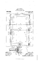
- Figure 1 is a view in elevation, with some parts broken away and some parts sectioned, looking at the inner side of a window and showing the sashes thereof supported in accordance with my invention.
- Fig. 2 is a fragmentary view in horizontal section approximately on the line 50 r of Fig. 1, but showing the upper sash lowered and in section, said parts being shown on a larger scale than in Fig. 1.
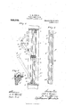
- Fig. 3 is a vertical section taken on the line a x of Fig. 1.
- Fig. 4- is a view in elevation corresponding to the direction in which it is observed in Fig. 3, but showing only the parallel sash-guiding channels; and
- Fig. 5 is a detail in section on the line 00 m of Fig. 1, the parts being shown on a larger scale than said Fig. 1.
- the numeral 1 indicates a window frame of the usual construction having outer stop strips 2, a weight box 3, inner casing 4: and inner stop strips 5.
- the upper sash is indicated by the numeral 6 and the lower sash by the numeral 7, and these two sashes are arranged to move vertically in close engagement with each other.
- the upper sash 6 is provided at its upper edge with an inset rod 8 and at its lower edge with an inset rod 9, while the lower sash is provided at its upper edge with an inset rod 10 and at its lower edge with an inset rod 11.
- the saidrods project beyond the side edges of the respective sash and form trunnions, but the trun nions formed by the rods 9 and 11 project farther than the trunnions formed by the rods 8 and 10 so as to afford the proper clear ance for cords 12 independently attached to the trunnions 9 and 11.
- the said cords 12 extend over the usual guide pulleys (not shown) and are provided with the usual window weights 13 that work in the cus tomary way within the boxes 3.
- the trunnions 8 and 9 of the upper sash are arranged to slide vertically in guide channels 14:, while the trunnions 10 and 11 of the lower sash are arranged to slide vertically in guide channels 15.
- the guide channels 14 and 15 are arranged in pairs and are secured closely together in parallel arrangement to the vertical portions of the window frame 1, between the outer stop strips 2 and inner stop strips 5. All of these guide channels 1d and 15 are preferably constructed of sheet metal folded into channel form with grooves 14; and 15 respectively, that extend from top to bottom thereof. The lower portions of the weight cords 12 work one in each of the said guide channels.
- the'inner flange of the inner guide channel 1a is provided at its intermedlate portion with a notch or trunnion passage 16, while the inner flanges of the outer guide channels 15 are provided with notches or trunnion passages 17 that aline with notches or trunnion passages 18 and 19, respectively, in the outer and inner flanges of the inner guide channels 1 1.
- the guide channels 14 and 15 are provided, respectively, in their boxes, with perforations or look bolt seats 20 and 21, also best shown in Fig. 4.
- the said sectional rods 9 and 11. are moved inward and out of engagement with the cooperating lock seats they leave the sashes free for vertical sliding movements.
- the inner ends of the sections thereof are preferably pivotally connected.
- the sashes 6 and 7 are adapted to be swung inward at their upper edges clear of the inner stop cleats 5.
- the upper trunnions 8 of the upper sash are located above the trunnion passages 17 18 and 19 and within the cooperating slots 15 of the guide channels 15, so that the upper sash is locked in its vertical position or against lateral swinging movement, and normally the upper trunnions 10 of the lower sash are below the trunnion passages 16 of the guide channels 1% and, hence, are held within the slots let so that the lower sash cannot be swung laterally inward.
- laterally movable stop strips 25 are seated between the said lower sash and the fixed stop cleats 5.
- Light bowed leaf springs 26 placed between the stop springs 25 and their seats in the window frame yieldingly press said strips outward in the position shown in Figs. 1 and 2, so that they overlap the sash 7.
- the sash-holding device comprises a pair of perforated segments 30 that are hinged at 31 to the window casings e1, so that when out of use they are adapted to be folded over against the casings, or inside wall, and when desired for use may be turned outward into a position at a right angle to the casing.
- a rod 32 is adapted to be passed through any of the alined perforations of the two segments 30 to hold the cooperating sash in any desired angular position; or, in other words, to open to any desired extent.
- arms 33 are pivoted to bearings 31 on the window casings and are perforated at their outer ends to permit the ends of the rod to be passed there through. These arms 33 also serve to hold the lock segments 30 in their out-turned or operative positions.
- Sashes mounted as above described may be opened to any desired extent so as to give the proper ventilation without so opening the window that drafts will be produced in the room.
- the same features of construction may be applied to many devices other than window sashes. It may find quite general utility as a closure for windows, doorways and other openings.
Description
N. H. CONGER.
WINDOW SASH SUPPORT. APPLIOAIIONIILED NOV. 11a, 1907.
928,362. Patented July 20,1909.
mums-SHEET 1.
N. H. GONGER.
I WINDOW SASH SUPPORT. APPLIGAT'IONIILED Nov. 18, 1907.
ILL? 5.
Patented July '20, 1909.
zgmmawmm 2.
;' "vim new. a. Emma 60.. PiKITo-LIINOGRAFNIRS. wAsmnGTou. u. c,
NOBLE H. GONGER, OF MINNEAPOLIS, MINNESOTA.
WINDQW-SASI'I SUPPORT.
Specification of Letters Patent.
Patented July 2c, 1909.
Application filed November 18, 1907. Serial No. 402,63.
To all whom it may concern:
Be it known that I, NOBLE H. CoNonR, a citizen of the United States, residing at Minneapolis, in the county of Hennepin and ffi'tate of Minnesota, have invented certain new and useful Improvements in Window- Sash Supports; and I do hereby declare the followingto be a full, clear, and exact description of the invention, such as will enable others skilled in the art to which it appertains to make and use the same.
My present invention has for its especial object to provide a window with improved means for adjustably supporting the sash thereof, but the novel features of construction therein involved are capable of more general use in connection with closures for openings, such as window and door openlugs.
The invention consists of the novel devices and combinations of devices hereinafter described and defined in the claims.
In the accompanying drawings which illustrate the invention, like characters indicate like parts throughout the several views.
Referring to the drawings, Figure 1 is a view in elevation, with some parts broken away and some parts sectioned, looking at the inner side of a window and showing the sashes thereof supported in accordance with my invention. Fig. 2 is a fragmentary view in horizontal section approximately on the line 50 r of Fig. 1, but showing the upper sash lowered and in section, said parts being shown on a larger scale than in Fig. 1. Fig. 3 is a vertical section taken on the line a x of Fig. 1. Fig. 4- is a view in elevation corresponding to the direction in which it is observed in Fig. 3, but showing only the parallel sash-guiding channels; and Fig. 5 is a detail in section on the line 00 m of Fig. 1, the parts being shown on a larger scale than said Fig. 1.
The numeral 1 indicates a window frame of the usual construction having outer stop strips 2, a weight box 3, inner casing 4: and inner stop strips 5. The upper sash is indicated by the numeral 6 and the lower sash by the numeral 7, and these two sashes are arranged to move vertically in close engagement with each other. The upper sash 6 is provided at its upper edge with an inset rod 8 and at its lower edge with an inset rod 9, while the lower sash is provided at its upper edge with an inset rod 10 and at its lower edge with an inset rod 11. The saidrods project beyond the side edges of the respective sash and form trunnions, but the trun nions formed by the rods 9 and 11 project farther than the trunnions formed by the rods 8 and 10 so as to afford the proper clear ance for cords 12 independently attached to the trunnions 9 and 11. The said cords 12 extend over the usual guide pulleys (not shown) and are provided with the usual window weights 13 that work in the cus tomary way within the boxes 3. The trunnions 8 and 9 of the upper sash are arranged to slide vertically in guide channels 14:, while the trunnions 10 and 11 of the lower sash are arranged to slide vertically in guide channels 15. The guide channels 14 and 15 are arranged in pairs and are secured closely together in parallel arrangement to the vertical portions of the window frame 1, between the outer stop strips 2 and inner stop strips 5. All of these guide channels 1d and 15 are preferably constructed of sheet metal folded into channel form with grooves 14; and 15 respectively, that extend from top to bottom thereof. The lower portions of the weight cords 12 work one in each of the said guide channels.
As best shown in Fig. l, the'inner flange of the inner guide channel 1a is provided at its intermedlate portion with a notch or trunnion passage 16, while the inner flanges of the outer guide channels 15 are provided with notches or trunnion passages 17 that aline with notches or trunnion passages 18 and 19, respectively, in the outer and inner flanges of the inner guide channels 1 1. The guide channels 14 and 15 are provided, respectively, in their boxes, with perforations or look bolt seats 20 and 21, also best shown in Fig. 4.
The heretofore noted trunnion-forming rods 9 and 11, in order that they may also constitute lock bolts, are made each in two sections, the said sections being free for limited sliding movements, so that when they are moved outward they are adapted to be inserted in one or the other of the cooperating seats 20 and 21, respectively, and when thus engaged lock the respective sashes 6 and 7 against sliding movements and to support the same with freedom for pivotal move ments. When the said sectional rods 9 and 11. are moved inward and out of engagement with the cooperating lock seats they leave the sashes free for vertical sliding movements. To provide for the above noted sliding movements of the rods 9 and 11 the inner ends of the sections thereof are preferably pivotally connected. to small bell crank levers 22 intermediately pivoted to the lower transverse bar portions of the respective sash and subject to approximately diamondshaped cam blocks 28 connected to the said bars for limited vertical sliding movements and preferably provided with projecting finger pieces 2- The said levers 22 and cam blocks 23 are set into seats formed within the lower bars of the respective sashes. As is evident, when the cam blocks are lowered as shown in Fig. 1, the sections of the rods 9 and 11 will be forced outward and when said cam blocks are raised the said rod sections will be moved inward. Furthermore, gravity tends to hold the cam blocks 23 in their lowered positions and, hence, the outer or trunnion acting ends of said rod sections 9 and 11 engage with one or the other of the lock seats 20 and 21. In Fig. 1 the upper sash is shown as locked in its uppermost position, and the lower sash is shown as locked in its lowermost position by the trunnions or projecting ends of the rods 9 and 11.
The sashes 6 and 7 are adapted to be swung inward at their upper edges clear of the inner stop cleats 5. Normally, however, the upper trunnions 8 of the upper sash are located above the trunnion passages 17 18 and 19 and within the cooperating slots 15 of the guide channels 15, so that the upper sash is locked in its vertical position or against lateral swinging movement, and normally the upper trunnions 10 of the lower sash are below the trunnion passages 16 of the guide channels 1% and, hence, are held within the slots let so that the lower sash cannot be swung laterally inward.
To form close joints between the inner vertical portions of the lower sash 7 and the window frame, laterally movable stop strips 25 are seated between the said lower sash and the fixed stop cleats 5. Light bowed leaf springs 26 placed between the stop springs 25 and their seats in the window frame yieldingly press said strips outward in the position shown in Figs. 1 and 2, so that they overlap the sash 7. To the ends of the springs 26 are attached small finger pieces 27 having beveled lock shoulders 28, which, when pressed inward, will engage loclr pins 29 secured to the adjacent stop cleats 5, as best shown in Figs. 1 and 5. lVhen the finger pieces 27 are thus engaged by the lock pins 29 they hold the springs 26 out of action so that the stop strips 25, when pressed inward, will remain in their innermost positions and thereby permit the outward swinging movement of the lower sash.
it must be lowered so that its upper trunnions 8 will be alined with and may be moved laterally inward through the trunnion passages 17, 1S and 19. When the lower sash is to be swung inward, as indicated by dotted lines in Fig. 3, it must be raised until its upper trunnions 10 are alined with and may be moved laterally inward through the trunnion passages 16. 1 preferably also provide devices for holding the upper and lower sash in different oblique in-turned positions, but in the drawings this device is shown as applied only for use in connection with the upper sash, while in practice the same device may be applied also to the lower sash. The sash-holding device, as shown in the drawings, comprises a pair of perforated segments 30 that are hinged at 31 to the window casings e1, so that when out of use they are adapted to be folded over against the casings, or inside wall, and when desired for use may be turned outward into a position at a right angle to the casing. A rod 32 is adapted to be passed through any of the alined perforations of the two segments 30 to hold the cooperating sash in any desired angular position; or, in other words, to open to any desired extent. Also as shown in the drawings, arms 33 are pivoted to bearings 31 on the window casings and are perforated at their outer ends to permit the ends of the rod to be passed there through. These arms 33 also serve to hold the lock segments 30 in their out-turned or operative positions.
Sashes mounted as above described may be opened to any desired extent so as to give the proper ventilation without so opening the window that drafts will be produced in the room. The same features of construction may be applied to many devices other than window sashes. It may find quite general utility as a closure for windows, doorways and other openings.
For convenience 1 have in the claims used the term sash, but this expression is not used in any way as a limitation to frames having glass panes therein, nor to devices for closing windows.
In the window construction above described itis important to note that the sashes be turned pivotally outer side in, so that the glass may be washed away from the interior of the room.
What 1 claim is:
1. The combination with a frame, of two pairs of laterally spaced vertical guide channels, upper and lower sashes having upper and lower projecting trunnions arranged to slide in said guide channels, certain of said trunnions being arranged for endwise movement for interlocking engagement with said guide channels, trunnion passages extending laterally through the inner flange of the inner guide channels whereby the lower or inner sash may be swung laterally when slid to a certain position, and lateral trunnion passages in the inner flanges of theouter guide channels and in the inner and outer flanges of said inner guide channels, whereby the upper or outer sash may be swung laterally inward when slid to a certain position, substantially as described.
2. The combination with a frame, of vertical guide channels secured therein, a window sash having projecting upper and lower trunnions arranged to slide in said guide channels, the lower of said trunnions having endwise movement for engagement with lock seats in said guide channels, and a fingeractuated device for simultaneously imparting endwise movements to said lower trunnions, substantially as described.
3. The combination with a frame, of vertical guide channels secured therein, a window sash having upper and lower trunnions arranged to slide in said guide channels, said guide channels having lateral trunnion passages permitting said sash to be swung laterally when slid to a certain position, and laterally movable stop strips mounted in said frame and adapted when moved outward to lock said sash against swinging movements, substantially as described.
l. The combination with a frame, of a sash 30 NOBLE H. CONGER. Witnesses H. D. KILGORE, F. D. MERCHANT.
Priority Applications (1)
| Application Number | Priority Date | Filing Date | Title |
|---|---|---|---|
| US40263407A US928362A (en) | 1907-11-18 | 1907-11-18 | Window-sash support. |
Applications Claiming Priority (1)
| Application Number | Priority Date | Filing Date | Title |
|---|---|---|---|
| US40263407A US928362A (en) | 1907-11-18 | 1907-11-18 | Window-sash support. |
Publications (1)
| Publication Number | Publication Date |
|---|---|
| US928362A true US928362A (en) | 1909-07-20 |
Family
ID=2996788
Family Applications (1)
| Application Number | Title | Priority Date | Filing Date |
|---|---|---|---|
| US40263407A Expired - Lifetime US928362A (en) | 1907-11-18 | 1907-11-18 | Window-sash support. |
Country Status (1)
| Country | Link |
|---|---|
| US (1) | US928362A (en) |
-
1907
- 1907-11-18 US US40263407A patent/US928362A/en not_active Expired - Lifetime
Similar Documents
| Publication | Publication Date | Title |
|---|---|---|
| US928362A (en) | Window-sash support. | |
| US752348A (en) | Hinge and automatic catch for awning-blinds | |
| US270309A (en) | la rue harrison | |
| US1024837A (en) | Hinge. | |
| US345694A (en) | Gboege hayes | |
| US589359A (en) | Sash-holder | |
| US846804A (en) | Gate-latch. | |
| US1294189A (en) | Window construction. | |
| US1343284A (en) | Window-shade | |
| US631484A (en) | Metallic window-shutter. | |
| US601680A (en) | Detachable sash | |
| US711082A (en) | Window. | |
| US358773A (en) | Ole flagstad | |
| US741457A (en) | Window. | |
| US790535A (en) | Window-guad. | |
| US983434A (en) | Sash-window. | |
| US802116A (en) | Sash-frame and sash. | |
| US230024A (en) | Hebman knubppel | |
| US1487767A (en) | Building ventilator construction | |
| US519333A (en) | Margaret e | |
| US595724A (en) | Adjustable window-screen | |
| US617482A (en) | engqvst | |
| US537207A (en) | Folding door | |
| US722533A (en) | Window. | |
| US960552A (en) | Window-sash. |