US928126A - Counterbalanced bearing for rotary journals. - Google Patents
Counterbalanced bearing for rotary journals. Download PDFInfo
- Publication number
- US928126A US928126A US46432208A US1908464322A US928126A US 928126 A US928126 A US 928126A US 46432208 A US46432208 A US 46432208A US 1908464322 A US1908464322 A US 1908464322A US 928126 A US928126 A US 928126A
- Authority
- US
- United States
- Prior art keywords
- load
- rotatable member
- bearing
- fluid
- pressure
- Prior art date
- Legal status (The legal status is an assumption and is not a legal conclusion. Google has not performed a legal analysis and makes no representation as to the accuracy of the status listed.)
- Expired - Lifetime
Links
- 239000012530 fluid Substances 0.000 description 73
- 238000010276 construction Methods 0.000 description 5
- 101100536354 Drosophila melanogaster tant gene Proteins 0.000 description 2
- 208000036366 Sensation of pressure Diseases 0.000 description 2
- 238000005192 partition Methods 0.000 description 2
- 241000257303 Hymenoptera Species 0.000 description 1
- 101150029237 Il11 gene Proteins 0.000 description 1
- 241001435619 Lile Species 0.000 description 1
- 230000007547 defect Effects 0.000 description 1
- 230000000694 effects Effects 0.000 description 1
- 239000002360 explosive Substances 0.000 description 1
- 239000007788 liquid Substances 0.000 description 1
- 230000013707 sensory perception of sound Effects 0.000 description 1
Images
Classifications
-
- F—MECHANICAL ENGINEERING; LIGHTING; HEATING; WEAPONS; BLASTING
- F04—POSITIVE - DISPLACEMENT MACHINES FOR LIQUIDS; PUMPS FOR LIQUIDS OR ELASTIC FLUIDS
- F04C—ROTARY-PISTON, OR OSCILLATING-PISTON, POSITIVE-DISPLACEMENT MACHINES FOR LIQUIDS; ROTARY-PISTON, OR OSCILLATING-PISTON, POSITIVE-DISPLACEMENT PUMPS
- F04C15/00—Component parts, details or accessories of machines, pumps or pumping installations, not provided for in groups F04C2/00 - F04C14/00
- F04C15/0042—Systems for the equilibration of forces acting on the machines or pump
Definitions
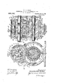
- Figure 1 represents in vertical section one form of a rotary engine embodying my invention, the section being taken on ine X-X of Fig. 2;
- Fig. 2 is a transverse vertical section on the line YY of Fig. 1.;
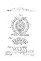
- Fig. 3 shows a different application of. my invention; and
- Figs. 4 and 5 show details of construction;
- I refer to counterbalance the load by means 0 the pressure of the fluid which exerts said load, so as to substitute to a great extent afiuid bearing for a mechanical frictional bearing, and to also cause the rotatable member on which the load is exerted to automatically varythe direction and amount of the ciounterbalancing pressure, but the prac- 8 in Fig. 2, so as to revolve in unison.
- Fig. 1, 1 indicates the casing of the engine provided with an entrance port 2 for the fluid under pressure, such as steam.
- 3 and 4 are rotatable elements or members fixed to their respective shafts 5 and 6, and may be geared together as indicated at 7
- Il11(l e rotatable member 4 is provided with a projection 9 extending outwardly from the axis of rotation and which I call a piston, and the rotatable member 3 with a cutaway portion 10 to receive the piston and, when in the proper position, to connect the entrance port 2 with the chamber 11 so as to admit steam I behindthe piston to drive the same and ro- 12 is an exhaust port connecting with the space between the casing and rotatable member 4 ahead of the iston.
- the rotating members are rovided with annular extensions indicated by 13 to 16, which fit closely in corresponding annular recesses surrounding the sides of the fixed members 20 and 26
- the steam which is in chamber 11 behind the piston exerts a heavy radial load upon the rotatable member 4 after thesteam is admitted, and as this member. rotates the resultant load will vary both in radial direction and in amount.
- the resultant will have advanced. one-halfthat distance, and when the rotatable mem ber has advanced 180 degrees, the resultant will have advanced 90 degrees, etc.-
- the load will obviously vary in amount due to the expansion of the steam and the increase of the area of the rotatable member which is exposed to the steam, and the resultant fricchamber 10 durin length of the beforementioned chord.
- I have preferably provided a series of chambers 30 31 locatedin the periphery of the fixed member 26- se arated by artitions 7'0 which-are preferab ly arranged diagonally.
- Figs. 4 and 5 show details of construction, Fig. 4 representing an enlarged portion of the rotatable member 4 and fixed member 26.
- Fig. 5 is a plan view of a portion of member 4 to show the preferred diagonal arrange ment of the chambers. It is desirable, on account of the speed-of the rotating member of a rotary engine and the appreciable time which it takes for the steam to pass through the passageways in member 4 and enter the countcrbalancing chambers, to lead the resultant of the countcrbalancing; ressure slightly ahead of the resultant of tie load, and in. order to do this I have formed the counterbalancing chambers (such for example as 80 31) as shown in Fig.
- the counterbalancing chambers such for example as 80 31
- the counterbalancing chambers are subs/initially closed against escape of the countcrbalancingz fluid, except through the passageways which communicate with the source of fluid supply.
- the chambers 19 and 22 in Fig. 1 are closed by the rotatable member 3, and although a very slight quantity of steam might leak beyond them, they would still be substantially closed.
- 1 may provide checks, one of which is indicated, for
- r is constant or whether that I do not confine myself to providing these auxiliary devices.
- a rotatable memberfa' fixed bearing member means for exerting a compressed-fluid radial load upon said rotatable member, means applying said compressed-fluid between said members in o 1 position to said load, and means automatic sultants ofthe. load 'and counterbalancing pressure to travel forward at substantially pne ha-lf the speed of's'aid rotatable member.
- a rotatable member a .ed bearing member, means for exerting a compressed-fluid radial load upon said rotatable. member, means applying said compressed-fluid between said members in 0 ppo-- sition to said load, means automaticallv causing the radial direction of the resultant s.
- a rotatable-member a 'fixed radial bearing for the same, means for exerting a fluid pressure on such an area of said rotatable member as results in a load toward said bearing,'means for exerting said fluid pressure between said member and jbearing on-an area of said rotatable member means for after-ward relieving said fluid res- I 4 sure therefrom, during one revolution 0 said esame in opposition to said lead, and mea'ns con .trolled by the movement of said rotatable member for simultaneously increasingboth said areasand afterward relieving-said fluid pressure therefrom during one revolution of; said rotatable member.”
- a casing a rotatablemember therein forming onesideoi a chamher in saidcasi-ng, a fixed radialbearing for said rotatable member, means for admitt ng a compressed-fluid to sa1d chamber and on suchan'area ofsaid-rotatablemember as re- .sults m a load toward said bearing, means pressures from said areas.
- a rotatable member in combination, a rotatable member, a fixed radial bearing for the same, meansior exerting a com ressed-iluid pressure on such anarea of sai rotatable member as results in a load toward said bearing, means for increasing such area, a series of substantially non-communicatii'ig spaces between said bearingand rotatable member, and meansfor introducing said. compressed fluid into said spaces in succession as saidarea is increased, said spaces beingso located thatthe resultant pressuretherein upon said rotatable member 0 poses the resultant pressure on said rotatab emember toward said bearmg. v v
- fixed radial bearing for these-me means for exerting a compressed-fluid pressure. on such an area of said rotatable member as results in a load toward said bearing, means for exciting sa1d fluid pressure between saidmember and -'beariug on an area of said rotatable member in'opposition to said load, and means'for r0 tating said member by the same fluid as exerts said load and thereby, simultaneously increasing both said areas.
- arotatable member surface at each side of said member, a '.il?. il,
- a fixed radial bearing .said rotatable member being arranged so i that the movement of the same increases both said areas in the direction of rotation, andmeans for thereafter relieving said pressures, all said operations occurring during one revolution of said rotatable member.
- a rotatablemember having axial extensions'which form a bearing surface at each side of said member, a fixed radial bearing for each extension, means for exerting a fluid pressure on such an area of said rotatable member as results in a load toward said fixed bearings, means for exerting, said fluid pressure between said fixed bearing and each-extension on such areas of said rotatable member as result in pressures in o osition to saidload, and means operated hy the rotation of said member for simultaneously increasing all said areas, and means for afterward relieving said pressures.
- a rotatable member for the same, means for exerting a steam pressure to rotate said member and on such an area of said rotatable member as results in a load toward said bearing, means for increasing such area in the direction of rotation as said member advances, a series of substantially non-communieating spaces between said bearing and rotatable member, passageways for the fluid which rotates said member to said spaces and operated by the rotation of said member as it advances for introducing steam which rotates said member into said said passageways being so arranged that at least one of said passage- Waysis in communication with each space at all times during said increase of area, said spaces being so located that the advancing resultant pressure therein u on said rotata ble m'ember opposes the a vancing result,-
- a rotatable member a fixed bearing member, means for exerting a compressed-fluid radial load upon said r0- tat'able member, means applying said com pressed fluid between sai members in opposition to said lead, means automatically chan ing the amount and radial direction of the oad and counterbalancing pressure whereby the fluid which exerts said lead also 0 poses said load during such changes, said changes being automatically controlled bysaid rotatable member at each revolution.
- a casing a rotatable member therein, apiston carried-by said rotatable member, means for introducing 'acompressed fluid into said casing. to act on one side of said piston and thereby rotate said member and to exert a radial fluid-pres sure load on one side of said rotatable member, a fixed bearing member, a series of chambers in the face of one of said members and closed by said other member, and means operated by said rotatable member for opening communication between said casing and said chambers in succession, said chambers being located to oppose the chan ing direction and amount of the radial Ioad upon said rotatable member.
- a casing a-rotatable member therein, a piston carried by. said rotatable member, means for. introducing a compressed fluid into said casing to act on one side of said piston and thereby rotate said member and to exert a radial'fluid-pressure load on one side of said rotatable member, a fixed bearing member, a series of chambers in the face of said fixed member and closed by said rotatable member, and means operated by said rotatable member for opening communication between said casin and said chambers in succession, said -munication between said casing and said 19 chambers in succession, said chambers be'v ing located to oppose the changing direction and amount'of the radial load upon said rotatable member.
- a. rotatable member having a central web and annular extensions at opposite sides thereof, a relatively fixed member inclosing the rotatablemember and recessed to receive the said extensions, chambers at opposite sides of the web between the faces of the fixed and rotatable members, means to introduce a co'unterbaL ancing fluid into such chambers, and means having fixed and rotafor increasing the area acted upon by such counterbalancing fluid.
- a rotatable pisto n-a rotatable member a fixed radial bearing for thesame, means for exerting a fluid pressure on such an area of said rotatable member as results in a load towardsaid bearing, means for exerting said fluid pressure between said member and bearing on an area of said rotatable member in opposition to said load, and means for simultaneously increasing both said areas.
- a rotatable member In combination, a rotatable member,
- a device of the class described the combination with a casing, of a fixed member longitudinally therein cylindrical in form a rotary member having a cylindrical portion surrounding said fixed member and rovided with perforations, separate cham ers being formed between said members throughout the circumference substantially "equal to the exposed outer area of said rotary member, a projection on. said'rotary member,
- the combination with a cylindrical casing and means for supplving afluid under pressure, of a rotary member therein carried y a central shaft, annular extensions upon 0 posite sides of said member, a fixed membeili annular recesses in which said extensions fit closely leaving the central outer part of the rotary member exposed to said fluid under pressure, chambers formed between said aving fixed and rotary members extending beneath said annular extensions beyond said exposed surface thesaid outer member being formed with passages leading from its outer exposed surface to said chambers, whereby the fluid under pressure will be admitted to said chambers and exert its force outwardly load upon said rotatable member w ich varies in area and direction.
- a relatively fixed member partitions on said fixed member extending bodily about as well as along the axis of said member forming separated chambers between said members, the said rotary member having passages therethrough communicating with chamber, and means for exerting a radial fluid pressure load upon said rotatable member which-varies in area and direction.
- central fixed bearing member fitting within said cylindrical portion.
Landscapes
- Engineering & Computer Science (AREA)
- Mechanical Engineering (AREA)
- General Engineering & Computer Science (AREA)
- Hydraulic Motors (AREA)
Description
G. P. HERRIGK.
GOUNTERBALANGED BEARING FOR ROTARY JOURNALS.
APPLICATION FILED NOV. 24, 1908.
Q Q I Am fim w m; M WA Wm 0 r HE H 0 Jw fit M2 J8 w z m M db m mm P. HERRIOK. BEARING FOR ROTARY JOURNALS.
N FILED NOV. 2
Patented July 13, 1909.
2 3HEETS-BHEET 2- GERARDUS POST HERRICK,"QF NEW YORK, N. Y.
COUNTERBALANCEII BEARING FOR ROTARY JOURNALS.
Specification of Letters Patent.
Patented July 13, 1909.
Application filed November 24, 1908. Serial No. 464,322.
load which would otherwise be exerted upon a frictional radial bearing, in order to obviate to a great extent the friction which would otherwise take place between the fixed and rotatable members of saidbearing.
While my invention may be applicable in a great variet of ways, it was primarily designed to obv1ate,to a reat extent, the friction between the rotata le andfix ed members of a radialbearing in which a load is exerted upon one side of the rotatable member, and W ich in some cases varies both in radial direction and amount.
In the drawings: Figure 1 represents in vertical section one form of a rotary engine embodying my invention, the section being taken on ine X-X of Fig. 2; Fig. 2 is a transverse vertical section on the line YY of Fig. 1.; Fig. 3 shows a different application of. my invention; and Figs. 4 and 5 show details of construction;
p In a rotary engine, that load which is the result of the ressure which is perpendicular to the axis 0 rotation on the rotatablemem ber, exerted by the steam which also rotates said member, varies both in direction and amount as the said member rotates. Such radial load has in most rotary engines resulted in an excessive loss of power due to mechanical friction between the bearings, re-' sulting in impairing the durability and efliciency in horse-power delivered by the engine. By my invention I have been enabled to counterbalance the greater part of the resultant load and so obviate the defects of such engines due to the'excessive loss from friction. I refer to counterbalance the load by means 0 the pressure of the fluid which exerts said load, so as to substitute to a great extent afiuid bearing for a mechanical frictional bearing, and to also cause the rotatable member on which the load is exerted to automatically varythe direction and amount of the ciounterbalancing pressure, but the prac- 8 in Fig. 2, so as to revolve in unison.
tate the moving elements.
Y around which they revolve.
tical use of my invention has shown that this is not necessary in all cases.
For the purpose of illustrating one application of my invention I have shown it in Figs. 1 to 5 in connection with a particular. type of rotary en ine, butit has no necessary imitation to such type and is applicable to other structures where it is desired to avoid the losses resulting from loads acting radiallyeither constant or variableto thrust one member axially toward another.
Referrlng to Fig. 1, 1 indicates the casing of the engine provided with an entrance port 2 for the fluid under pressure, such as steam. 3 and 4 are rotatable elements or members fixed to their respective shafts 5 and 6, and may be geared together as indicated at 7 Il11(l e rotatable member 4 is provided with a projection 9 extending outwardly from the axis of rotation and which I call a piston, and the rotatable member 3 with a cutaway portion 10 to receive the piston and, when in the proper position, to connect the entrance port 2 with the chamber 11 so as to admit steam I behindthe piston to drive the same and ro- 12 is an exhaust port connecting with the space between the casing and rotatable member 4 ahead of the iston. It will be obvious that as the memer 4 rotates in the direction of the arrow, the piston will enter the recess 10, and, as soon as the recess connectswith port 2, steam will be admitted behind the piston and soon thereafter be cutoff, and the steam in cham ber 11 behind the piston will then continue to rotate the same, and such steam be export 12.
In the particular embodiment of my invention shown in Figs. 1 and 2, the rotating members are rovided with annular extensions indicated by 13 to 16, which fit closely in corresponding annular recesses surrounding the sides of the fixed members 20 and 26 It will be obvious that the steam which is in chamber 11 behind the piston exerts a heavy radial load upon the rotatable member 4 after thesteam is admitted, and as this member. rotates the resultant load will vary both in radial direction and in amount.
.hausted'when the piston passes the exhaust Other. things bcin equal, the direction of the drawn fro the point indicated by 17 toKthe point on the rotatable member 4 indicated y 18, where the rear face of the piston meets the surface of the member 4. It will be obvious that such perpendicular would change its direction as the member rotates and that this perpendicular ,or resultant would advance in the direction of rotation at a less speed than (in the resent embodiment at one-half the speed or) the speed of the rotatable member 4. For example, when the rotatablememberhas-advanced 90 degrees,
the resultant will have advanced. one-halfthat distance, and when the rotatable mem ber has advanced 180 degrees, the resultant will have advanced 90 degrees, etc.- The load will obviously vary in amount due to the expansion of the steam and the increase of the area of the rotatable member which is exposed to the steam, and the resultant fricchamber 10 durin length of the beforementioned chord.
v and practically "constant in amount. radia tional load would correspond to the varying This load would therefore exert upon the bearing of the rotatable member 4 a radial load which varies both-in direction and amount,
unlesssaidload. is cbun-ter-balanced in some way. The pressure of the steam passing through the entrance port' 2 also obviously exerts a fluid pressure upon the outer face of the memberB'Which is constant in direction,
load exerted by the steam inchamber 11 upon the member 3 will obviously be constant in direction, butwill vary in amount due to the variation of the pressure of the fluid in chamber 11; 'As there is steam in the'greater part of the revolution of mem er 3, this steam will obviously exert a radial load upon the member .3 which varies both in direction andamount on account of its rotation and the reduction of the steam pressure. These loads have insurmounta member relatively fixed with relation thereto'(such as the caring of therotatable member) so as to exert 'u on said rotatable .member a fluid-pressure w liich is opposed to the direction of the radial-load whether this load is constant in direction or varies, and
whether it is constant in amount or not. In. the embodiment shown in the drawings 1' have preferred to accomplish this by providing one or more chambers between the bear- The fix 11 and-22 so thatthe steam from. chamber 11 will enter chamber 22. It will be obvious ingfaces of the rotatable and fixed members, said chamber or chambers being so. located, and the fluid being so introduced, as to automatically and effectively counterbalance the load. "In such :constructions as shown in Fig. 1 such chamber may be in-the'face of the rotatable member or; in the face of the fixed member, depending upon what condition is present. In most cases, however, I prefer to locate this chamberv or chambers in the face of the fixed member as shown. 19 is one'of such chambers in the face of the fixed member 20 opposite the port 2. It will'be obvious that-if steam under boiler pressure is admitted to this chamber 19, it will oppose the radial had upon member 3 which is exerted at the entrance port 2. I prefer to ro' vide a passageway 2-1 through the edmember 20 and between the source of supply 2 and the chamber 19, so that steam ma readily pass thereto to counterbalance this erly proportioned. to this end; In the con struct on shown the chamber -.19 is divided into two sections on opposite sides of the central web of the member 3. 22 represents another chamber or chambers in the .fiXed member 20- opposite the upper end of chamber 11, and 23 is a passageway in the ed member and connecting said chambers that-the steam in chamber 22 will vary in pressure as the steam in chamber ll-varies, and therefore will counterbalance the vary ing radial load at this point. This load is constant-in direction.
In order to counterbalance the loader:- erted by the steam in the recess-10, I have provided a'chamber 24 which in this case is in the face of the rotatable member and which will therefore rotate with the recess 10. The passageway 25 connects these two chambers.
In order to counterbalance the radial load on therotatingmember 4, I have preferably provided a series of chambers 30 31 locatedin the periphery of the fixed member 26- se arated by artitions 7'0 which-are preferab ly arranged diagonally. It will be obvioils that as the parts rotate the' piston will pass exhaust port .12 and there Wlll then-be -load, the area of the chamber 19 being prop practically no steam load upon the member 5 4, but'as the piston enters recess-10 and moves farther on ;to the osition indicated by dotted lines at 27 (who e recesslO has just established communication between the in,- let port and the chamber behind the iston) steam will'immediately be admitted t rough the assag'eways 28, 29 to the chambers 30 31 in t e fixed member 26, and the ressure of steam will therefore be exerte in those chambers in opposition to the radial load exerted by the steam in the chamber 11 behip d 'thepiston. As seen in Fig. 2, I prefera ly have a series of such coun'terbalancing chambers in the periphery of each hub of the fixed member. As the combined area of the chambers to which the steam is admitted from the chamber 11, is substantially equal to the effective exterior area of the rotatable member 4, which is behind the piston at any given time, the radial load at any given time will be substantially counterbalanced. As the member 4 continues to rotate thepiston will move from the dotted line position toward the position shown in full lines, and as the rotatable member is provided with a succession of passageways through it, which communicate successively with the counterbalancing chambers, the advance (in the direction of rotation) of the resultant steam pressure load will be automatically counteralanced by the similarly advancing resultant counterbalancing steam pressure. It will be observed that in the embodiment shown in the drawings the resultant of the load on the outside of the rotatable member and the resultant of the counterbalancing pressure will both advance in the direction of the rotation and at a less speed than (in the resent embodiment at one-half the spee of) the s )eed of the rotatable member. In the en. o iment shown the supply of steam is cut off when the piston is moved a short distance from its dotted line position, and thereafter the steam is used expansive-1y, reducing in pressure as the piston progresses, and as the counterbalancing chambers are successively opened to the space behind the piston and the pressure in the chambers istherefore equal, the varying direction and amount of the radial load is automatically counterbalanced. 7
It will be observed that when steam is first admitted to the chamber formed behind the piston, steam pressure is exerted on such an area of said rotatable member as results in a load toward. the bearing, and that as the steam enters through the passageways into the counterbalancing space the pressure is also exerted between the rotatable member and the bearing on such an area of the retatable member as results in a pressure in oposition to said load, and that as the rotatable member and piston advance both said areas will be simultaneously increased be cause the outside area exposed to the steam will be increased and the area of the r9tatable member exposed to the internalnountcrbalancing pressure will also be increased. In order to accomplish this increase of area exposed to the counterbalancing pressure I prefer to provide a succession of chambers as shown, but this may not be necessary in all cases. As for example, only to have them part wayaround, or as in Fig. 3, forexample, which shows a form of rotatable member 34 which may be substituted for the member 4, it is notnecessary to provide a series of from chamber 38 by passageway 39 to this counterbalancing chamber 36, and so counterbalance the varying direction and amount of the load, substantially the same as inthe series of chambers shown in F ig. 1. V
It will be observed that in Fig. 3 and also -in the lower half of Figs. 1 and 2, the passage ways are all 1n the rotatable member, but 1n the upper half of Figs. and 2 the passageways indicated by 21 and 23 are stationarily located and are formed in the fixed members.
Figs. 4 and 5 show details of construction, Fig. 4 representing an enlarged portion of the rotatable member 4 and fixed member 26. Fig. 5 is a plan view of a portion of member 4 to show the preferred diagonal arrange ment of the chambers. It is desirable, on account of the speed-of the rotating member of a rotary engine and the appreciable time which it takes for the steam to pass through the passageways in member 4 and enter the countcrbalancing chambers, to lead the resultant of the countcrbalancing; ressure slightly ahead of the resultant of tie load, and in. order to do this I have formed the counterbalancing chambers (such for example as 80 31) as shown in Fig. 5; This will lead the steam slightly ahead of the rear of the piston and so compensate for the delay in exerting effective pressure in the counterbalancing chambers. In order to keep the counterbalancing chambers which are behind the piston in communication at all times with that part of the chamber 11 formed bohind the piston, I have preferably spaced the passageways through the member 4 a dis tance apart such. that the distance between centers of any two adjacent passageways will be substantially equal to the width of a cross section of a chambm', as indicated in Fig. 4. It will therefore be evident that each cminterbalancing chamber behind the piston at any time will be in communication through at least one passageway with the chamber 11 behind the piston, and the pres- .srncsthefii'nwill therefore be substantially equal at all times. The counterbalancing chambers are subs/initially closed against escape of the countcrbalancingz fluid, except through the passageways which communicate with the source of fluid supply. For example, the chambers 19 and 22 in Fig. 1 are closed by the rotatable member 3, and although a very slight quantity of steam might leak beyond them, they would still be substantially closed. If desired, 1 may provide checks, one of which is indicated, for
example, as a spring-pressed check 40 to prevent passage of any leak of steam be ally. causing theradml direction of the retween chamber 19 and chamber 22. I also may provide recesses 41 and 42 which may open to the atmosphere, if desired, so'that any steam leaking tothem will be prevented frompassing beyond such escape ports and perhaps otherwise exerting an undesirable Y steamprossure. Itwill be obvious,however,
r is constant or whether that I do not confine myself to providing these auxiliary devices.
It will be observed from the foregoing that I have provided constructions by which a counterbalancing effect may be produced either by the fluid which exerts the load or which is independent thereof, and Whether the direction and amount of the radial load both vary or only one varies.
While I have particularly referred to steam as the motor and counterbalancing fluid, my invention is applicable to engines operated by steam, and to explosive as well as ex ansion engines,- and in other apparatus w ere other fluids or liquids are used. j
From the foregoing it will be seen that my invention is applicable to different structures Where there is normally friction resulting from the rotation of one member upon or in respect to another member, and whether the friction results from the rotation of. a loaded shaft (as the shaft 5 or 6 1) in its hearings, or additionally Wherefriction would otherwise result from the wear of the shafts causing the members carried by the shafts to be brought frictionally against other parts of the structure.
. While I have described abovefone embodiment of my invention, it will be obvious that it may be embodied in widely varied forms and is applicable to widely varying conditions, and I therefore do not limit myself to the applications 'or to, the particular constructions or arrangements which I have described and illustrated.
. What I claim is: 1 'v 1. In combination, a'rotatablemember, a
' fixedbearing member, means for exerting a causin compressed-fluid radial load upon said rota table ,member, means applyingsaid com pressed-fluid between sair members-in opposition tosaid load, and means automatically the radial direction of the result .ants o the load and countcrbalancing pressure to travel'forward at a less speed'than that of said rotatable member.
2. In combination, a rotatable memberfa' fixed bearing member, means for exerting a compressed-fluid radial load upon said rotatable member, means applying said compressed-fluid between said members in o 1 position to said load, and means automatic sultants ofthe. load 'and counterbalancing pressure to travel forward at substantially pne ha-lf the speed of's'aid rotatable member. 3. In. combinatiom a rotatable member, a 1
pressed-fluid between said members in oppo-.
sition to said load, and means automatically causing the radial direction of the resultants of the load and counterbalancing pressure to travel forward at a'less speed than that of said rotatable member, and means for relieving both said pressures.
5. In combination, a rotatable member, a .ed bearing member, means for exerting a compressed-fluid radial load upon said rotatable. member, means applying said compressed-fluid between said members in 0 ppo-- sition to said load, means automaticallv causing the radial direction of the resultant s.
of the load and counterbalancing pressure to travel forward at substantially one-half the speed ofsaid rotatable member, said changes being automatically controlled by said rota- 4 table member, and means for exhausting said loadand 'counterbalanemg pressure, all said operations takmg place during one revolution of said rotatable me'mber.- i 6. In combination, a rotatable member, a
fixed radial bearing for the same, means for exerting a fluid pressure on such an area of said rotatable member as results in a load toward said bearing, means for exerting said fluid pressure between said member and bearing on an area of said rotatable member in 0 position to said load, and means for simu taneously increasing both said areas.
7. Incombination, a rotatable member, a fixed radial bearing for the same, means for.
exerting a fluid pressure. on such an area'of said rotatable member asresults in a load toward said bearing,-mea11s for exerting said fluid pressure between said member and bearing on an area of said rotatable member in opposition. to said lead, means for simultaneously increasmg both sald areas, and
rotatable member.
8. In combination, a rotatable-member, a 'fixed radial bearing for the same, means for exerting a fluid pressure on such an area of said rotatable member as results in a load toward said bearing,'means for exerting said fluid pressure between said member and jbearing on-an area of said rotatable member means for after-ward relieving said fluid res- I 4 sure therefrom, during one revolution 0 said esame in opposition to said lead, and mea'ns con .trolled by the movement of said rotatable member for simultaneously increasingboth said areasand afterward relieving-said fluid pressure therefrom during one revolution of; said rotatable member." I
9. ln combination a rotatable member, a fxed radial bearing'forthesame, means for exerting a fluid pressurebn such an area ofsaid rotatable member as 're'sultsina load toward said bearing, means for exerting said fluid pressure between saidniember and bearing on an area of said rotatable memberino positlon to sa1d load,'and'- means'for,
" simu taneously increasing both said areas during one revolution; of said r'otat-able'memher, and means for relieving said fluid presher in said casing, a fixedradial bearing for said-rotatable member, means for admitting v a compressed-fluid to said cham'ber and on such an areazof .said rotatable member as results in a'load toward said bearing, means for exerting said fluid pressure between said member and bearing on an area of said rotatable member opposition tol said load, and means for simultaneousl increasing both said areas, c
12. Inconibination, a casing, a rotatablemember therein forming onesideoi a chamher in saidcasi-ng, a fixed radialbearing for said rotatable member, means for admitt ng a compressed-fluid to sa1d chamber and on suchan'area ofsaid-rotatablemember as re- .sults m a load toward said bearing, means pressures from said areas.
for exertingusaid fluid pressure between said member and bearing on an area of said rotatable member in opposition tosaid load,
means for simultaneously increasing both sa1d areas, and means for relieving sa1d fluid -13. in combination, a rotatable member, a fixed radial bearing for the same, meansior exerting a com ressed-iluid pressure on such anarea of sai rotatable member as results in a load toward said bearing, means for increasing such area, a series of substantially non-communicatii'ig spaces between said bearingand rotatable member, and meansfor introducing said. compressed fluid into said spaces in succession as saidarea is increased, said spaces beingso located thatthe resultant pressuretherein upon said rotatable member 0 poses the resultant pressure on said rotatab emember toward said bearmg. v v
14. In combination, a rotatable member, a
l fixed radial bearing for the same, meansfor exerting a com ressed-fluid pressure on such an area of sa1 rotatable member as results in a load towardsaid bearing, means for increasing such area aseries of substantially non-communicating spaces between said bearing and rotatable member, and means comprising a-passageway'to each chamberopened by saidrot-at'able member as it advances for introducing said compressed fluid mto sa1d spaces n succession as sa1d area 18 increased; sa1d spaces bemg so located that the resultant pressure therein uponsaid ro-, tatable member op oses the resultant pressure on said rotata ,le member-toward said b a 15. Inlcombination, a-rotatable member, a
fixed radial bearingffor the same, means for exerting a compressed fluid pressure on such an area of said rotatable member as results ina load toward said bearing, means for in.- creasing sucharea, a series of substantially non-communicating spaces between said bearingand rotatablemember, and, means for introducing sa1d compressed fluid sa1d spaces in successlon as sa1d area 1s mcreased, said spaces being so located that the resultantvpressure therein 11 on said rotatable .1
member, 0 oses the resu tant pressure on i said rotata lile member toward. said bearing,
and means for-relieving said fluid pressure from both said member and said spaces.
' 16: In combination, arotatable member, a.
fixed radial bearing for the same, means'for exerting a compressed-fluid pressure on such 'anarea of said rotatable member as results -1I1 a load toward sa1d bearing, means for mcreasing such area, a series cit-substantially non-communicating spaces m the face of said flxed bearing member-and closed by said ro-. tatable member, and means for introducing said compressed fluid into said spacesin sucsession as said area is increased, said spaces being-so located that .the resultant pressure therein u on said rotatable member opposes" the resu tant pressure on said rotatable member toward said bearing.
17. In combination, a rotatable member, a
. fixed radial bearing for these-me, means for exerting a compressed-fluid pressure. on such an area of said rotatable member as results in a load toward said bearing, means for exciting sa1d fluid pressure between saidmember and -'beariug on an area of said rotatable member in'opposition to said load, and means'for r0 tating said member by the same fluid as exerts said load and thereby, simultaneously increasing both said areas.
.18. In combination, arotatable member surface at each side of said member, a '.il?. il,
. having axialextensions which form a bearing radial bearing for such extension, means for exerting a fluid pressure on such an area of said rotatable member as results in a load toward said fixed bearin s, means for exerting said fluid pressure bearing and each extension on such areas of said rotatable member as result in pressures 1 mwopposition to said load, and means for sitat'ab e member and said piston, means for introducing steam into said chamber and thereby exerting a load on said rotatable member toward saidbearing and on the piston to rotate the same, means for introducing steam from said chamber between said rotatable member and bearing on an area of said rotatable member to oppose said. load,
My... Man. 1 i
. a fixed radial bearing .said rotatable member being arranged so i that the movement of the same increases both said areas in the direction of rotation, andmeans for thereafter relieving said pressures, all said operations occurring during one revolution of said rotatable member.
20. In combination, a rotatablemember having axial extensions'which form a bearing surface at each side of said member, a fixed radial bearing for each extension, means for exerting a fluid pressure on such an area of said rotatable member as results in a load toward said fixed bearings, means for exerting, said fluid pressure between said fixed bearing and each-extension on such areas of said rotatable member as result in pressures in o osition to saidload, and means operated hy the rotation of said member for simultaneously increasing all said areas, and means for afterward relieving said pressures.
21. In combination, a rotatable member, for the same, means for exerting a steam pressure to rotate said member and on such an area of said rotatable member as results in a load toward said bearing, means for increasing such area in the direction of rotation as said member advances, a series of substantially non-communieating spaces between said bearing and rotatable member, passageways for the fluid which rotates said member to said spaces and operated by the rotation of said member as it advances for introducing steam which rotates said member into said said passageways being so arranged that at least one of said passage- Waysis in communication with each space at all times during said increase of area, said spaces being so located that the advancing resultant pressure therein u on said rotata ble m'ember opposes the a vancing result,-
etween said fixed pressed fiuid'between said members in opposition to said load, means automatically changing the amount and radial direction of the load and counterbalancing pressure whereby the fiuidwhich exerts said load also ,opposes said load-during such changes, said changes beingautomatlcally controlled by said rotatable member. 1
23. In combination, a rotatable member, a fixed bearing member, means for exerting a compressed-fluid radial load upon said r0- tat'able member, means applying said com pressed fluid between sai members in opposition to said lead, means automatically chan ing the amount and radial direction of the oad and counterbalancing pressure whereby the fluid which exerts said lead also 0 poses said load during such changes, said changes being automatically controlled bysaid rotatable member at each revolution.-
24. In combination, a casing, a rotatable member therein, apiston carried-by said rotatable member, means for introducing 'acompressed fluid into said casing. to act on one side of said piston and thereby rotate said member and to exert a radial fluid-pres sure load on one side of said rotatable member, a fixed bearing member, a series of chambers in the face of one of said members and closed by said other member, and means operated by said rotatable member for opening communication between said casing and said chambers in succession, said chambers being located to oppose the chan ing direction and amount of the radial Ioad upon said rotatable member.
25. In combination, a casing, a-rotatable member therein, a piston carried by. said rotatable member, means for. introducing a compressed fluid into said casing to act on one side of said piston and thereby rotate said member and to exert a radial'fluid-pressure load on one side of said rotatable member, a fixed bearing member, a series of chambers in the face of said fixed member and closed by said rotatable member, and means operated by said rotatable member for opening communication between said casin and said chambers in succession, said -munication between said casing and said 19 chambers in succession, said chambers be'v ing located to oppose the changing direction and amount'of the radial load upon said rotatable member.
27. In combination, a casing, a rotatable member therein, a piston carried by said rotatable member, means for introducing a compressed fluid into said casing to act on one side of said. piston and thereby rotate said member and to exert a radial fluid-pres sure loadon one side of said rotatable member, a fixed bearing member, aseries of,
chambersin the face of saidrelatively fixed member and closed by said rotatablemem- -ber, and a series of ports in said rotatable member for opening communication between sa d casing and said chambers m successlon, said chambers being located tooppose the changing direction and amount of theradial load upon said rotatable member.
28. In combination, a rotatable member,.-
a relatively fixed member, means for exertmg a radial fluid-pressure load upon said rotatable member which vanes in direction,
, means'for introducing a ,counterbalancing means resulting in'a load upon oneside of the fluid-pressure between said members in advance of said load as the direction changes and'maintaining the same in 'opposition'to said load. a
means for accumulating such'load and counterbalancing pressure after thefirst application of such pressure. I
30. In a bearing table members, means whereby a pressure is applied to one side of the center of the bearing to rotate the rotatable member, and a chamber at the same side of the'axis of rotation, means for admitting fluid pressure thereto to counterbalance the motor pressure, and means for thereafter accumulating both saidpressures. g
31. In a bearing a. rotatable member having a central web and annular extensions at opposite sides thereof, a relatively fixed member inclosing the rotatablemember and recessed to receive the said extensions, chambers at opposite sides of the web between the faces of the fixed and rotatable members, means to introduce a co'unterbaL ancing fluid into such chambers, and means having fixed and rotafor increasing the area acted upon by such counterbalancing fluid. I 1
32 In combination, a rotatable pisto n-a rotatable member, a fixed radial bearing for thesame, means for exerting a fluid pressure on such an area of said rotatable member as results in a load towardsaid bearing, means for exerting said fluid pressure between said member and bearing on an area of said rotatable member in opposition to said load, and means for simultaneously increasing both said areas. 33. In combination, a rotatable member,
a fixed member, means forexerting a radial fluid-pressure load upon said rotatable member which varies in dlrectlon, means for 1ntroducing a counterbalancing fluid-pressurebetween said members in advance of said load as the direction changes "and maintaining the'same in opposition to said'load. v
, 34. In a device of the class described, the combination with a casing, of a fixed member longitudinally therein, a rotary member surrounding said fixed member,-a projection on said rotary member, means forconfining a fluid under pressure in said casing behind said projection between it and a fixed point I of the casing to drive said rotary member, and means for admitting the said fluid under piessure between said members fromsaid ed point to said projection at all points of the revolution the. area to which it is ad-- mitted being at all times substantially equal to the area of the outer surface of said rotary memberbetween said fixed point and pro is jection and being so proportioned as to equalize the ressure. I I
' 35:; n a device of the class described, the combination with a casing, of a fixed member longitudinally therein cylindrical in form a rotary member having a cylindrical portion surrounding said fixed member and rovided with perforations, separate cham ers being formed between said members throughout the circumference substantially "equal to the exposed outer area of said rotary member, a projection on. said'rotary member,
means for confining a fluid under ressure in said casing behind'said projection etween it and a fixed point of the casing whereby the rotary member will be driven and the axial" ressure on its outer surface will be equalized y the counteracting pressure within the chambers. f 36. Ina deviceof the class described, the combination with a cylindrical casing and means for supplving afluid under pressure, of a rotary member therein carried y a central shaft, annular extensions upon 0 posite sides of said member, a fixed membeili annular recesses in which said extensions fit closely leaving the central outer part of the rotary member exposed to said fluid under pressure, chambers formed between said aving fixed and rotary members extending beneath said annular extensions beyond said exposed surface thesaid outer member being formed with passages leading from its outer exposed surface to said chambers, whereby the fluid under pressure will be admitted to said chambers and exert its force outwardly load upon said rotatable member w ich varies in area and direction. a 38. In combination, a rotatable member,
a relatively fixed member, partitions on said fixed member extending bodily about as well as along the axis of said member forming separated chambers between said members, the said rotary member having passages therethrough communicating with chamber, and means for exerting a radial fluid pressure load upon said rotatable member which-varies in area and direction.
39. In combination, a rotatable member,
2 a relatively fixed member, diagonal partitions on said fixed member spaced e ual distances apart forming separated cham ers between said members, the said rotary member having passages therethrough communicating wlth said chambers, spaced apart distances equal to the fwidtliof said chambers and at the advance end of said diagonal artitions, and means for ex'e'rtinga radial i uid pressure load upon said rotatable member which variesin area and direction.-
40. In a device of the class described, the combination with'a casing, 'of a rotary mem' ber having a cylindrical portion fitting therein and'having in its outer surface a central longitudinal recess to; which 'fluid'under pressure is admitted and in its under surface a corresponding recess extending beyond the'end of said outer recess, a passage,
ther'ethrough connecting said recesses, and a.
central fixed bearing member fitting within said cylindrical portion.
41. In a device of the class described, the
combination with a casing of arotary mem her having a cylindrical outer surface including an annular extension on each. side fitting said therein, the said member bein With'a central longitudinal flui pressurechamber in its outer surface extending part way into said annular extcnsions and the under surfaces of said extensions being provided with chambers corresponding in radial position to the outer chamber, but extending beyond the ends thereof, and the said extensions having passages therethrough joining said chambers and afixed bearing member containing oppositely disposed cylindrical portions fitting within saidannular extensions.
42. In a device of the class described, the combination with a casing having a cylindrical opening therein, of a rotary member within said casing having annular extensions beyond the edge of said casing, fixed bearing members secured to said casing upon opposite sides and having annular grooves to fit and receive said extensions, means for supplying fluid under presfsureto the outer surface of said rotaryminber at its central portion throughout a part of the outer circumference, and means for admitting said fluid under pressure beneath said extensions to such an area as to balance said pressure on the outer circumference. I
43. In combination, a rotatable member, a
provided fixed bearing member, means for exertinga fluid pressure load toward said bearing member, upon an area of said rotatable member, means for applying a fluid under ressure upon an areaof said rotatable mem-' ber "between said members in opposition to said load, and means forincreasing both said areas pressureload upon an area of said rotatable member toward said fixed membcr,:-means' for exerting 1a fluid pressure loadin opposition thereto upon said rotatable member between said members, means for increasing the area" acted upon by said first mentioned dead andvarying the amount of said opposin load.
a, n testimony whereof I aflix my signature in presence of two witnesses.
GERARDUS POST HERRIQK. Witnesses CHARLES FOSTER, ARTH R L. BRYANT.
44. In combination, a rotatable member, a fixed member, means, for exerting a fluid
Priority Applications (1)
| Application Number | Priority Date | Filing Date | Title |
|---|---|---|---|
| US46432208A US928126A (en) | 1908-11-24 | 1908-11-24 | Counterbalanced bearing for rotary journals. |
Applications Claiming Priority (1)
| Application Number | Priority Date | Filing Date | Title |
|---|---|---|---|
| US46432208A US928126A (en) | 1908-11-24 | 1908-11-24 | Counterbalanced bearing for rotary journals. |
Publications (1)
| Publication Number | Publication Date |
|---|---|
| US928126A true US928126A (en) | 1909-07-13 |
Family
ID=2996552
Family Applications (1)
| Application Number | Title | Priority Date | Filing Date |
|---|---|---|---|
| US46432208A Expired - Lifetime US928126A (en) | 1908-11-24 | 1908-11-24 | Counterbalanced bearing for rotary journals. |
Country Status (1)
| Country | Link |
|---|---|
| US (1) | US928126A (en) |
Cited By (1)
| Publication number | Priority date | Publication date | Assignee | Title |
|---|---|---|---|---|
| US2960039A (en) * | 1954-04-15 | 1960-11-15 | Phivretveit Karsten Alfred | Rotary fluid pumps and motors and the like |
-
1908
- 1908-11-24 US US46432208A patent/US928126A/en not_active Expired - Lifetime
Cited By (1)
| Publication number | Priority date | Publication date | Assignee | Title |
|---|---|---|---|---|
| US2960039A (en) * | 1954-04-15 | 1960-11-15 | Phivretveit Karsten Alfred | Rotary fluid pumps and motors and the like |
Similar Documents
| Publication | Publication Date | Title |
|---|---|---|
| US2255785A (en) | Fluid pressure device | |
| US2335284A (en) | Rotary fluid pressure device | |
| US3170297A (en) | Hydrostatic thrust bearing device | |
| US2658456A (en) | Fluid displacement device | |
| US2255787A (en) | Fluid pressure device and system | |
| US2255783A (en) | Fluid pressure device and system | |
| US2937294A (en) | Dynamoelectric device with fluid supported rotor | |
| US2845941A (en) | Plate valve for rotary units | |
| US3932073A (en) | Screw rotor machine with spring and fluid biased balancing pistons | |
| GB1273246A (en) | Pressure loaded gear pump or motor | |
| US2158933A (en) | Rotary compressor | |
| GB1069874A (en) | Variable ratio transmission | |
| US2173432A (en) | Hydraulic pump or motor | |
| US2962972A (en) | Power transmission | |
| US3289606A (en) | Axial piston pump or motor arrangement | |
| US928126A (en) | Counterbalanced bearing for rotary journals. | |
| US1967167A (en) | Fluid compression apparatus | |
| JPS61142372A (en) | vane motor device | |
| US2022610A (en) | Pump | |
| US2319238A (en) | Fluid pressure device | |
| GB743088A (en) | Improvements relating to rotary pumps and motors | |
| US1924629A (en) | Hydraulic pump and motor | |
| US1642095A (en) | Fluid dynamometer | |
| US2255784A (en) | Fluid pressure device | |
| US2975716A (en) | Rotary engine, in particular fluid transmission |