US9254446B2 - Suspended play structure - Google Patents
Suspended play structure Download PDFInfo
- Publication number
- US9254446B2 US9254446B2 US14/322,218 US201414322218A US9254446B2 US 9254446 B2 US9254446 B2 US 9254446B2 US 201414322218 A US201414322218 A US 201414322218A US 9254446 B2 US9254446 B2 US 9254446B2
- Authority
- US
- United States
- Prior art keywords
- suspended
- play structure
- support
- sidewall
- floor
- Prior art date
- Legal status (The legal status is an assumption and is not a legal conclusion. Google has not performed a legal analysis and makes no representation as to the accuracy of the status listed.)
- Active
Links
- 239000000463 material Substances 0.000 claims description 16
- 239000004677 Nylon Substances 0.000 claims description 7
- 229920001778 nylon Polymers 0.000 claims description 7
- 239000002184 metal Substances 0.000 claims description 3
- 229910052751 metal Inorganic materials 0.000 claims description 3
- 229920000728 polyester Polymers 0.000 claims description 2
- 239000004033 plastic Substances 0.000 claims 1
- 238000000034 method Methods 0.000 description 11
- 230000008901 benefit Effects 0.000 description 2
- 238000012986 modification Methods 0.000 description 2
- 230000004048 modification Effects 0.000 description 2
- 238000009958 sewing Methods 0.000 description 2
- 238000003466 welding Methods 0.000 description 2
- 229910000831 Steel Inorganic materials 0.000 description 1
- 229910052782 aluminium Inorganic materials 0.000 description 1
- XAGFODPZIPBFFR-UHFFFAOYSA-N aluminium Chemical compound [Al] XAGFODPZIPBFFR-UHFFFAOYSA-N 0.000 description 1
- 238000005266 casting Methods 0.000 description 1
- 239000000470 constituent Substances 0.000 description 1
- 238000002788 crimping Methods 0.000 description 1
- 238000005520 cutting process Methods 0.000 description 1
- 238000005553 drilling Methods 0.000 description 1
- 230000000694 effects Effects 0.000 description 1
- 239000006260 foam Substances 0.000 description 1
- 238000005242 forging Methods 0.000 description 1
- 238000004519 manufacturing process Methods 0.000 description 1
- 239000000843 powder Substances 0.000 description 1
- 239000007787 solid Substances 0.000 description 1
- 239000010959 steel Substances 0.000 description 1
- 238000007514 turning Methods 0.000 description 1
Images


Classifications
-
- A—HUMAN NECESSITIES
- A63—SPORTS; GAMES; AMUSEMENTS
- A63H—TOYS, e.g. TOPS, DOLLS, HOOPS OR BUILDING BLOCKS
- A63H33/00—Other toys
- A63H33/008—Playhouses, play-tents, big enough for playing inside
Definitions
- the field of the invention generally relates to play structures. More specifically, the invention relates to a play structure designed to be suspended from a support.
- the hanging chair can only support a single child, while the present invention is intended to support multiple children simultaneously.
- top and bottom rings that are affixed to straps support the structures of the present invention to provide support for the additional weight.
- the cushion used in the present invention is inserted within an internal floor pocket and is secured with a zipper closure.
- the larger structure of the present invention permits the addition of a window opening that is not present in the smaller hanging chair.
- the optional lights can add further decorativeness and usefulness in a dark or night environment of the present invention.
- a suspended play structure that can be used indoors and outdoors, is enclosed, can support more than one child, is thrilling and exciting, and can be produced at low cost.
- a suspended play structure that includes a removable cushion, reinforced nylon strapping, a built in door flap, one or more windows, and removable lights.
- the invention relates to various exemplary embodiments, including articles, structures, play structures, and various methods of using the same.
- FIG. 1 is a perspective view of the suspended play structure.
- FIG. 2 is a front perspective side view of the suspended play structure of FIG. 1 .
- FIG. 3 is a perspective side view of the suspended play structure of FIG. 1 .
- FIG. 4 is a back perspective back to side view of the suspended play structure of FIG. 1 .
- FIG. 5 is a perspective side view of the suspended play structure of FIG. 1 .
- FIG. 6 is a perspective side view of the suspended play structure of FIG. 1 .
- FIG. 7 is a perspective side view of the suspended play structure of FIG. 1 .
- FIG. 8 is a perspective top view of the suspended play structure of FIG. 1 .
- FIG. 9 is a perspective bottom view of the suspended play structure of FIG. 1 .
- FIG. 10 is a close-up view of the hanging ring of the suspended play structure of FIG. 1 .
- FIG. 11 is a perspective view of string lights.
- FIG. 12 is a perspective view of two arc-shaped pieces that come together to form the internal support rings.
- FIG. 13 is a perspective view of a plain first end of an arc-shaped piece.
- FIG. 14 is a perspective view of a tubular receptacle of an arc-shaped piece.
- FIG. 15 is a perspective view of a tubular receptacle of an arc-shaped piece.
- FIG. 16 is a perspective view of the bottom ring from inside the suspended play structure of FIG. 1 .
- FIG. 17 is a perspective view of the bottom ring from inside the suspended play structure of FIG. 1 .
- FIG. 18 is a perspective view of the internal pocket and zipper closure of the suspended play structure of FIG. 1 .
- FIG. 19 is a perspective view of the top layer of the floor from inside the suspended play structure of FIG. 1 .
- FIG. 20 is a perspective view of the roof from inside the suspended play structure of FIG. 1 .
- FIG. 21 is a perspective view of the doorway and door flap of the suspended play structure of FIG. 1 .
- FIG. 22 is a perspective view of a portion of the doorway and door flap of the suspended play structure of FIG. 1 .
- FIG. 23 is a perspective view of a portion of the doorway and door flap of the suspended play structure of FIG. 1 .
- FIG. 24 is a perspective view of the doorway and door flap of the suspended play structure of FIG. 1 .
- FIG. 25 is a perspective view of the doorway and door flap of the suspended play structure of FIG. 1 .
- FIG. 26 is a perspective view of the door flap of the suspended play structure of FIG. 1 .
- FIG. 27 is a perspective view of the door flap of the suspended play structure of FIG. 1 .
- FIG. 28 is a perspective view of the roof from inside the suspended play structure of FIG. 1 .
- FIG. 29 is a perspective view of the top ring from inside the suspended play structure of FIG. 1 .
- FIG. 30 is a perspective view of the top ring from inside the suspended play structure of FIG. 1 .
- FIG. 31 is a perspective view of the top ring from inside the suspended play structure of FIG. 1 .
- FIG. 32 is a perspective view of a window from inside the suspended play structure of FIG. 1 .
- FIG. 33 is a perspective view of the roof from inside the suspended play structure of FIG. 1 .
- FIG. 34 is a perspective view of a window from inside the suspended play structure of FIG. 1 .
- FIG. 35 is a perspective view of a window and the roof from inside the suspended play structure of FIG. 1 .
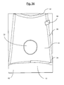
- FIG. 36 is a perspective view of a window from inside the suspended play structure of FIG. 1 .
- FIG. 37 is a perspective view of the string lights and attachment points from inside the suspended play structure of FIG. 1 .
- the suspended play structure 10 includes a floor 12 , a sidewall 14 , and a roof 16 .
- the floor 12 , sidewall 14 , and roof 16 may individually and collectively be made from one or many pieces of material.
- the sidewall 14 is made from several pieces of material attached together through sewing.
- the suspended play structure 10 may include support straps 30 embedded within, or attached to, the floor 12 , sidewall 14 , and/or roof 16 .
- the set of support straps 30 may loop around a hanging ring 18 and continue down the roof 16 , down the sidewall 14 , and to the floor 12 .
- the support straps 30 may connect to one another within or near the floor 12 .
- the suspended play structure 10 may be suspended from an external support.
- the external support 20 may include any support strong enough to support the suspended play structure 10 and any occupants thereof.
- Exemplary external supports 20 include tree limbs, a stand, a ceiling (e.g., a hook securely attached to joists above the ceiling), or other supports.
- the stand may be a powder-coated stand that can be supported on the ground.
- the play structure 10 may be hung from one or more support points by nylon straps and S hooks.
- the sidewall 14 may include one or more windows 22 .
- Each window 22 may include a cutout or other hole in the sidewall 14 located approximately 6′′ to 10′′ from where the sidewall 14 meets the floor 12 .
- Each window 22 may be oval shaped.
- the sidewall 14 may also include a doorway 24 through which an individual may enter the interior space of the suspended play structure 10 .
- the doorway 24 may be teardrop shaped as shown, while other doorway shapes are within the scope of the invention.
- the doorway 24 may include a door flap 26 .
- the door flap 26 may be secured to the sidewall 14 on one side and may be secured in place over the doorway 24 through the use of hook and loop fasteners.
- the suspended play structure 10 may include a top ring 32 and a bottom ring 34 .
- the top ring 32 and bottom ring 34 may be made of a strong material, such as metal (e.g., steel, aluminum, or others), and may be substantially covered in a cushioning material, such as foam.
- the top ring 32 and bottom ring 34 assist in providing additional structural support to the suspended play structure 10 .
- the top ring 32 may be of a narrower diameter than the bottom ring 34 .
- the top ring 32 and bottom ring 34 may be positioned such that the support straps 30 interact with the outer circumferences of the top ring 32 and bottom ring 34 (i.e., the support straps 30 are located farther outside of the center of the suspended play structure 10 than the top ring 32 and bottom ring 34 .)
- the top ring 32 may be pre-installed and may be a single, solid piece.
- the bottom ring 34 may be installable by an end user and may come in multiple pieces.
- the bottom ring 34 is made of four separable arc-shaped pieces 36 that attach together end-to-end.
- Each separable arc-shaped piece has a plain first end 38 and a second end with a tubular receptacle 40 sized to fit around the plain first end 38 of an adjacent arc-shaped piece 36 .
- the tubular receptacle includes a set screw 42 configured to provide additional friction to the plain first end of the adjacent arc-shaped piece when the bottom ring 34 is fully assembled.
- the bottom ring 34 may fit within a set of sleeves located on the inner side of the sidewall 14 or the inner side of the floor 12 .
- the sleeves may include permanent sleeves having openings on a first end and a second end, but otherwise being permanently sewn or otherwise attached to the suspended play structure 10 .
- the sleeves may also include openable sleeves, the openable sleeves being formed of one or more pieces of material having hook and loop fasteners thereon and being able to be positioned around the bottom ring 34 and secured in place with opposing hook and loop fasteners located on either the inner side of the sidewall 14 or the inner side of the floor 12 .
- the floor 12 includes a bottom layer 60 and a top layer 62 , thus forming an internal pocket.
- the internal pocket may be accessible through a zipper closure 28 .
- the internal pocket may be configured to contain an internal cushion 50 .
- the internal cushion 50 may only be accessible through the zipper closure 28 . Therefore, when inside suspended play structure 10 , the internal cushion 50 would provide support for a user through the top layer 62 of the floor 12 .
- attachment points 80 may be located on the sidewall 14 or roof 16 and may be located at the intersection of the sidewall 14 and the roof 16 .
- the attachment points 80 may be made from a loop of hook and loop fastener material that interacts with hook and loop fastener material sewn or otherwise attached to the sidewall 14 and/or roof 16 . In this fashion, the attachment points 80 may be used to removably secure accessories.
- the attachment points 80 are used to suspend a set of string lights 90 .
- the string lights 90 may include a battery power pack 92 , an on/off switch, and a set of LED lights 94 .
- the suspended play structure 10 may include an accessory pocket 96 into which the battery power pack 92 may be placed and/or secured.
- the floor 12 , sidewall 14 , and roof 16 of the suspended play structure 10 may be made from canvas, or from approximately 100% nylon and may have trim reinforced with nylon.
- the support straps 30 may be made from nylon webbing.
- the internal cushion 50 may include approximately 100% polyester filling (e.g., polyfill).
- the suspended play structure 10 may be capable of holding up to approximately 250 lbs.
- the play structure has dimensions of about 54′′H ⁇ 44′′W, the stand is about 48′′W ⁇ 48′′D ⁇ 84′′H, and the strap is about 100′′L ⁇ 11 ⁇ 2′′W.
- FIGS. 3-6 show another view of the suspended play structure 10 of the present invention.
- window 22 is shown in FIG. 3 to be opposite the doorway 24 , deployed in a circular shape.
- Other shapes of windows are also within the scope of the invention.
- Hanging ring 18 is shown suspended from hanging support 20 .
- the play structure 10 includes roof 16 , sidewall 14 , and floor 12 .
- a second window 22 is shown in FIGS. 4-6 , as a single or multiple windows 22 may be deployed with the invention.
- FIG. 7 also shows the suspended play structure 10 suspended from a hanging support 20 by hanging ring 18 .
- the play structure 10 includes roof 16 , sidewall 14 , and floor 12 .
- the floor 12 can be observed more readily within the structure 10 when the door flap 26 that normally covers the doorway 24 is held in an open position.
- the top layer 62 of the floor 12 can be seen in this view.
- the top layer 62 is designed to support one or more children.
- FIG. 8 shows a top view of the suspended play structure 10 to provide details of the hanging ring 18 , the roof 16 , the sidewall 14 , and a window 22 .
- the roof 16 and sidewall 14 are generally made of canvas or similar material.
- FIG. 9 shows a bottom view of the play structure 10 to provide a detailed view of the floor 12 , including the bottom layer 60 of the floor 12 .
- the zipper 28 for opening the internal pocket (not shown) is seen as well.
- FIG. 10 shows a view of the roof 16 of the play structure, including the hanging ring 18 attached thereto by support strap 30 that loops around hanging ring 18 .
- the hanging ring 18 is then fastened to a support structure 20 to support the play structure.
- FIG. 11 shows a string of lights 90 that can be used with the play structure of the present invention.
- the string lights 90 may include a battery power pack 92 , an on/off switch, and a set of LED lights 94 .
- FIGS. 12-16 show the arc-shaped pieces 36 that can be used to form the rings used in the present invention.
- one of the rings can be made of four separable arc-shaped pieces 36 that attach together end-to-end.
- Each separable arc-shaped piece has a plain first end 38 comprising a male attachment end and a second end with a tubular receptacle 40 comprising a female attachment end sized to fit around the plain first end 38 of an adjacent arc-shaped piece 36 .
- the tubular receptacle includes a set screw 42 configured to provide additional friction to the plain first end of the adjacent arc-shaped piece 36 when the bottom ring 34 is fully assembled.
- FIG. 16 shows the bottom ring 34 deployed within sidewall 14 through an openable sleeve.
- FIG. 17 shows another view of the bottom ring 34 from inside the play structure.
- the arc-shaped pieces 36 are seen between the openable sleeves fit together to form the ring 34 .
- the top layer 62 of the floor 12 is seen with the openable sleeves around the edge to hold the bottom ring 34 .
- a support strap 30 is shown running up the side of the play structure within the wall.
- FIG. 18 shows the internal pocket between the top layer and the bottom layer 60 of the floor 12 .
- the internal cushion can be supported within this pocket.
- the top layer 62 of the floor 12 is shown in FIG. 19 , where the internal cushion 50 would be located under the top layer 62 .
- Support straps 30 are also shown within the walls 14 of the structure.
- a window 22 is shown in a portion of the wall.
- the support ring 34 and internal cushion 50 are located within or under other layers and cannot actually be seen in this view.
- FIG. 20 shows a view of the roof 16 of the play structure from inside.
- Four support straps 30 are shown to support the play structure. They run from the top of the structure down to the bottom ring.
- the top ring 32 is shown within a sleeve between the roof 16 and the walls that include a window 22 .
- FIGS. 21-27 show a doorway 24 that is covered by a flap 26 .
- the doorway 24 can be opened or closed for ingress or egress to the inside of the play structure.
- Hook-and-loop fasteners shown in FIGS. 23 and 26 - 27
- FIG. 24 shows the flap 26 partially opened to provide a view of the floor 12 within the play structure
- FIG. 25 shows the flap 26 secured in the open position to show the top layer 62 of the floor 12 within the play structure.
- FIGS. 28-31 and 34 show the inside of the play structure.
- attachment points 80 may be located on the sidewall 14 or roof 16 and may be located at the intersection of the sidewall 14 and the roof 16 .
- the attachment points 80 may be made from a loop of hook-and-loop fastener material that interacts with hook-and-loop fastener material sewn or otherwise attached to the sidewall 14 and/or roof 16 . In this fashion, the attachment points 80 may be used to removably secure accessories.
- the top ring 32 is shown supporting the roof 16 and the sidewall 14 .
- the top ring 32 is removably secured inside sleeves using hook-and-loop fasteners.
- the attachment points 80 are attached to the sleeves.
- An accessory pocket 96 as described above, is shown in FIG. 36 .
- FIGS. 32-33 and 35 show various features of the suspended play structure from the inside.
- a window 22 is shown in the sidewall 14 .
- the top ring 32 and the bottom ring 34 support the structure.
- Support straps 30 run from the top of the structure to the bottom ring 34 .
- the internal cushion 50 is located under the top layer 62 of the floor 12 .
- An attachment point 80 for accessories is located near the roof 16 .
- FIG. 37 shows the support structure implemented with internal lighting.
- a battery power pack 92 is held within accessory pocket 96 .
- a string of LED lights 94 runs along the top ring 32 at the top of the structure between the roof 16 and the sidewall 14 . The string is held in place at the attachment points. The string will provide lighting within the support structure so that the structure can be used at night or in dark conditions for activities that require light, such as reading.
Abstract
Description
Claims (15)
Priority Applications (2)
| Application Number | Priority Date | Filing Date | Title |
|---|---|---|---|
| US14/322,218 US9254446B2 (en) | 2013-07-03 | 2014-07-02 | Suspended play structure |
| US14/977,909 US9630119B2 (en) | 2013-07-03 | 2015-12-22 | Suspended play structure |
Applications Claiming Priority (2)
| Application Number | Priority Date | Filing Date | Title |
|---|---|---|---|
| US201361842742P | 2013-07-03 | 2013-07-03 | |
| US14/322,218 US9254446B2 (en) | 2013-07-03 | 2014-07-02 | Suspended play structure |
Related Child Applications (1)
| Application Number | Title | Priority Date | Filing Date |
|---|---|---|---|
| US14/977,909 Continuation-In-Part US9630119B2 (en) | 2013-07-03 | 2015-12-22 | Suspended play structure |
Publications (2)
| Publication Number | Publication Date |
|---|---|
| US20150018108A1 US20150018108A1 (en) | 2015-01-15 |
| US9254446B2 true US9254446B2 (en) | 2016-02-09 |
Family
ID=52277510
Family Applications (1)
| Application Number | Title | Priority Date | Filing Date |
|---|---|---|---|
| US14/322,218 Active US9254446B2 (en) | 2013-07-03 | 2014-07-02 | Suspended play structure |
Country Status (1)
| Country | Link |
|---|---|
| US (1) | US9254446B2 (en) |
Cited By (8)
| Publication number | Priority date | Publication date | Assignee | Title |
|---|---|---|---|---|
| US9988824B2 (en) | 2016-02-11 | 2018-06-05 | Canaima Outdoors, Inc. | Treepod assembly |
| USD821110S1 (en) * | 2016-10-21 | 2018-06-26 | Nicholas McDonald | Suspended chair |
| USD827080S1 (en) | 2017-02-10 | 2018-08-28 | Canaima Outdoors, Inc. | Hanging pod |
| USD828697S1 (en) * | 2016-12-13 | 2018-09-18 | Worldwide Creations, LLC | Cylindrical hanging chair |
| USD831749S1 (en) | 2017-08-08 | 2018-10-23 | Canaima Outdoors, Inc. | Hanging tent structure |
| USD845656S1 (en) * | 2016-10-31 | 2019-04-16 | Nicholas McDonald | Suspended chair |
| USD902610S1 (en) * | 2020-06-04 | 2020-11-24 | Yuli Sun | Hammock |
| US11185149B2 (en) | 2019-02-06 | 2021-11-30 | 0950300 B.C. Ltd. | Inflatable portable ledge apparatus |
Families Citing this family (22)
| Publication number | Priority date | Publication date | Assignee | Title |
|---|---|---|---|---|
| CN204245635U (en) * | 2014-11-03 | 2015-04-08 | 杭州兆世进出口有限公司 | A kind of hanging basket chair |
| USD820609S1 (en) | 2016-07-28 | 2018-06-19 | Worldwide Creations, LLC | Hanging chair |
| USD821109S1 (en) | 2016-07-28 | 2018-06-26 | Worldwide Creations, LLC | Hanging chair |
| USD819349S1 (en) | 2016-07-28 | 2018-06-05 | Worldwide Creations, LLC | Hanging chair |
| USD827317S1 (en) | 2016-07-28 | 2018-09-04 | Worldwide Creations, LLC | Hanging chair |
| USD804835S1 (en) * | 2016-07-28 | 2017-12-12 | Worldwide Creations, LLC | Hanging chair |
| USD820608S1 (en) | 2016-07-28 | 2018-06-19 | Worldwide Creations, LLC | Hanging chair |
| RU2682287C2 (en) * | 2017-05-17 | 2019-03-18 | Гульнара Зуфаровна Андрианова | Frameless suspended rocking chair |
| USD865383S1 (en) | 2017-06-21 | 2019-11-05 | Worldwide Creations, LLC | Football-shaped hanging chair |
| USD829454S1 (en) | 2017-06-21 | 2018-10-02 | Worldwide Creations, LLC | Football-shaped hanging chair |
| USD871785S1 (en) | 2018-02-01 | 2020-01-07 | Worldwide Creations, LLC | Spherical-shaped hanging chair |
| USD917908S1 (en) | 2019-04-26 | 2021-05-04 | Worldwide Creations, LLC | Chair |
| USD899112S1 (en) | 2019-05-06 | 2020-10-20 | Worldwide Creations, LLC | Chair |
| USD898397S1 (en) | 2019-05-06 | 2020-10-13 | Worldwide Creations, LLC | Chair |
| USD938179S1 (en) | 2019-11-27 | 2021-12-14 | Worldwide Creations, LLC | Chair |
| USD968143S1 (en) | 2020-02-12 | 2022-11-01 | Worldwide Creations, LLC | Chair with legs |
| USD985321S1 (en) | 2020-04-28 | 2023-05-09 | Worldwide Creations, LLC | Chair |
| USD982853S1 (en) * | 2021-08-23 | 2023-04-04 | Shaoming Huang | Outdoor cat tower |
| USD971526S1 (en) * | 2021-08-23 | 2022-11-29 | Shaoming Huang | Outdoor pet playpen tent |
| USD994992S1 (en) * | 2021-11-03 | 2023-08-08 | Yongquan Yu | Pet playpen |
| USD994230S1 (en) * | 2021-11-03 | 2023-08-01 | Yongquan Yu | Pet playpen |
| USD988454S1 (en) * | 2023-01-19 | 2023-06-06 | Jiali Chen | Round shaped baby play mat |
Citations (7)
| Publication number | Priority date | Publication date | Assignee | Title |
|---|---|---|---|---|
| US2661010A (en) * | 1948-10-29 | 1953-12-01 | Powers & Company | Tent |
| US3545461A (en) | 1968-08-20 | 1970-12-08 | Everett R Carlson | Tree suspended enclosure |
| US4526307A (en) | 1984-07-06 | 1985-07-02 | Parker Ronald J | Portable combination tent and backpack |
| US4825578A (en) * | 1988-05-27 | 1989-05-02 | Robinson James L | Portable blind apparatus |
| US6088953A (en) | 1998-02-20 | 2000-07-18 | Morgan; Wayne | Collapsible protective plant cover |
| US7455427B1 (en) * | 2005-06-27 | 2008-11-25 | Paul Freeman | Lighted tent apparatus and system |
| WO2009007740A1 (en) | 2007-09-13 | 2009-01-15 | Live Life Outdoors International Limited | Suspendable tent |
-
2014
- 2014-07-02 US US14/322,218 patent/US9254446B2/en active Active
Patent Citations (7)
| Publication number | Priority date | Publication date | Assignee | Title |
|---|---|---|---|---|
| US2661010A (en) * | 1948-10-29 | 1953-12-01 | Powers & Company | Tent |
| US3545461A (en) | 1968-08-20 | 1970-12-08 | Everett R Carlson | Tree suspended enclosure |
| US4526307A (en) | 1984-07-06 | 1985-07-02 | Parker Ronald J | Portable combination tent and backpack |
| US4825578A (en) * | 1988-05-27 | 1989-05-02 | Robinson James L | Portable blind apparatus |
| US6088953A (en) | 1998-02-20 | 2000-07-18 | Morgan; Wayne | Collapsible protective plant cover |
| US7455427B1 (en) * | 2005-06-27 | 2008-11-25 | Paul Freeman | Lighted tent apparatus and system |
| WO2009007740A1 (en) | 2007-09-13 | 2009-01-15 | Live Life Outdoors International Limited | Suspendable tent |
Non-Patent Citations (8)
| Title |
|---|
| Alavi, Farima, Daily Delight: Nestrest Hammock, Blog Post, May 12, 2012, http://blog.hgtv.com/design/2012/05112/daily-delight-nestrest-hammock/. |
| Black Diamond Equipment, Cliff Cabana Double Portaledge, Webpage Capture, Jul. 3, 2013, http://blackdiamonequipment.com/en/big-wall-climbing/cliff-cabana-double-portaledge-BD8104510000ALL1.html#q=portaledge&start=2. |
| DEDON, Nestrest Fact Sheet, PDF Download, Jul. 2, 2013, http://www.dedon.de. |
| Hang-In-Out LLP, Cacoon by hang-in-out, Webpage Capture, Jul. 2, 2014, http://www.hang-in-out.com/. |
| Hearthsong, HugglePod(TM) Hanging Chair, Webpage Capture, Jun. 25, 2014, http://www.hearthsong.com/room-play-spaces/hugglepod-indooroutdoor-canvas-hanging-chair.htm. |
| Hearthsong, HugglePod™ Hanging Chair, Webpage Capture, Jun. 25, 2014, http://www.hearthsong.com/room-play-spaces/hugglepod-indooroutdoor-canvas-hanging-chair.htm. |
| Sesungguhnya, Nylon Canvas HugglePodTMHangOut with LED Lights, Blog Post, Jul. 3, 2012, jukardeseman32.blogspot.com/2012/07/nylon-canyas-hugglepodtmhangout-with.html. |
| Tentsile, Tentsile Stingray, Webpage Capture, Jul. 2, 2013, http://www.tentsile.com. |
Cited By (9)
| Publication number | Priority date | Publication date | Assignee | Title |
|---|---|---|---|---|
| US9988824B2 (en) | 2016-02-11 | 2018-06-05 | Canaima Outdoors, Inc. | Treepod assembly |
| USD821110S1 (en) * | 2016-10-21 | 2018-06-26 | Nicholas McDonald | Suspended chair |
| USD845656S1 (en) * | 2016-10-31 | 2019-04-16 | Nicholas McDonald | Suspended chair |
| USD828697S1 (en) * | 2016-12-13 | 2018-09-18 | Worldwide Creations, LLC | Cylindrical hanging chair |
| USD848753S1 (en) * | 2016-12-13 | 2019-05-21 | Worldwide Creations, LLC | Cylindrical hanging chair |
| USD827080S1 (en) | 2017-02-10 | 2018-08-28 | Canaima Outdoors, Inc. | Hanging pod |
| USD831749S1 (en) | 2017-08-08 | 2018-10-23 | Canaima Outdoors, Inc. | Hanging tent structure |
| US11185149B2 (en) | 2019-02-06 | 2021-11-30 | 0950300 B.C. Ltd. | Inflatable portable ledge apparatus |
| USD902610S1 (en) * | 2020-06-04 | 2020-11-24 | Yuli Sun | Hammock |
Also Published As
| Publication number | Publication date |
|---|---|
| US20150018108A1 (en) | 2015-01-15 |
Similar Documents
| Publication | Publication Date | Title |
|---|---|---|
| US9254446B2 (en) | Suspended play structure | |
| US9630119B2 (en) | Suspended play structure | |
| US6244486B1 (en) | Article carrier | |
| US10952522B2 (en) | Veteran support backpack | |
| US9580928B1 (en) | Adaptable tent system with interconnecting member | |
| CN103945688B (en) | Animal enclosures | |
| US4526307A (en) | Portable combination tent and backpack | |
| US7228820B1 (en) | Expandable animal kennel | |
| WO2010068711A2 (en) | Bag | |
| EP3024991A1 (en) | Hanging structures having zome geometry | |
| JP2005248698A (en) | Tent with window having inner shelf | |
| US10070712B2 (en) | Utility backpack | |
| US20140274430A1 (en) | Swing System and Method of Use | |
| US20100123341A1 (en) | Baby swing car seat system | |
| US20120167484A1 (en) | Storage Device and methods of assembling and Utilizing the Same | |
| WO2008121341A2 (en) | Portable sheltered environments | |
| US4239135A (en) | Multipurpose rucksack | |
| US10781965B2 (en) | Portable storage assembly | |
| KR200471475Y1 (en) | Roof top tent accessories | |
| US20170159320A1 (en) | Tent System and Method | |
| US20230022893A1 (en) | Ice chest liner | |
| US20090137183A1 (en) | Portable puppet theater, stage, or playhouse apparatus and methods | |
| KR101260413B1 (en) | Tent of interior space extension type | |
| WO2015031618A1 (en) | Convertible shelter and tent structure | |
| EP2275627A1 (en) | A self-deployable tunnel tent and a method of packing it |
Legal Events
| Date | Code | Title | Description |
|---|---|---|---|
| AS | Assignment |
Owner name: PLOW & HEARTH LLC, VIRGINIA Free format text: ASSIGNMENT OF ASSIGNORS INTEREST;ASSIGNORS:LACY, AMANDA T;FRIES, BEVERLY;XU, TING;SIGNING DATES FROM 20140630 TO 20140701;REEL/FRAME:033231/0837 |
|
| AS | Assignment |
Owner name: WELLS FARGO BANK, NATIONAL ASSOCIATION, MASSACHUSE Free format text: SECOND SUPPLEMENT TO GRANT OF SECURITY INTEREST IN UNITED STATES PATENTS;ASSIGNOR:PLOW & HEARTH, LLC;REEL/FRAME:034280/0588 Effective date: 20141031 |
|
| STCF | Information on status: patent grant |
Free format text: PATENTED CASE |
|
| AS | Assignment |
Owner name: PLOW & HEARTH, LLC, VIRGINIA Free format text: PARTIAL RELEASE OF SECURITY INTEREST IN PATENTS;ASSIGNOR:WELLS FARGO BANK, NATIONAL ASSOCIATION;REEL/FRAME:045850/0009 Effective date: 20171231 |
|
| AS | Assignment |
Owner name: CHILDREN'S GROUP, LLC, VIRGINIA Free format text: ASSIGNMENT OF ASSIGNORS INTEREST;ASSIGNOR:PLOW & HEARTH, LLC;REEL/FRAME:046342/0501 Effective date: 20180101 |
|
| FEPP | Fee payment procedure |
Free format text: MAINTENANCE FEE REMINDER MAILED (ORIGINAL EVENT CODE: REM.); ENTITY STATUS OF PATENT OWNER: LARGE ENTITY |
|
| FEPP | Fee payment procedure |
Free format text: SURCHARGE FOR LATE PAYMENT, LARGE ENTITY (ORIGINAL EVENT CODE: M1554); ENTITY STATUS OF PATENT OWNER: LARGE ENTITY |
|
| MAFP | Maintenance fee payment |
Free format text: PAYMENT OF MAINTENANCE FEE, 4TH YEAR, LARGE ENTITY (ORIGINAL EVENT CODE: M1551); ENTITY STATUS OF PATENT OWNER: LARGE ENTITY Year of fee payment: 4 |
|
| FEPP | Fee payment procedure |
Free format text: ENTITY STATUS SET TO SMALL (ORIGINAL EVENT CODE: SMAL); ENTITY STATUS OF PATENT OWNER: SMALL ENTITY |
|
| MAFP | Maintenance fee payment |
Free format text: PAYMENT OF MAINTENANCE FEE, 8TH YR, SMALL ENTITY (ORIGINAL EVENT CODE: M2552); ENTITY STATUS OF PATENT OWNER: SMALL ENTITY Year of fee payment: 8 |
|
| AS | Assignment |
Owner name: TIGER CAPITAL GROUP, LLC, MASSACHUSETTS Free format text: ASSIGNMENT OF ASSIGNORS INTEREST;ASSIGNOR:CHILDREN'S GROUP, LLC;REEL/FRAME:066650/0791 Effective date: 20240220 |
|
| AS | Assignment |
Owner name: REGAL GAMES LLC, ILLINOIS Free format text: ASSIGNMENT OF ASSIGNORS INTEREST;ASSIGNOR:TIGER CAPITAL GROUP, LLC;REEL/FRAME:066668/0125 Effective date: 20240304 |