US3545461A - Tree suspended enclosure - Google Patents
Tree suspended enclosure Download PDFInfo
- Publication number
- US3545461A US3545461A US754026A US3545461DA US3545461A US 3545461 A US3545461 A US 3545461A US 754026 A US754026 A US 754026A US 3545461D A US3545461D A US 3545461DA US 3545461 A US3545461 A US 3545461A
- Authority
- US
- United States
- Prior art keywords
- enclosure
- section
- attached
- rope
- ropes
- Prior art date
- Legal status (The legal status is an assumption and is not a legal conclusion. Google has not performed a legal analysis and makes no representation as to the accuracy of the status listed.)
- Expired - Lifetime
Links
- 238000012856 packing Methods 0.000 description 12
- 239000000725 suspension Substances 0.000 description 11
- 241000238631 Hexapoda Species 0.000 description 4
- 238000010276 construction Methods 0.000 description 4
- 238000012986 modification Methods 0.000 description 3
- 230000004048 modification Effects 0.000 description 3
- 241000272525 Anas platyrhynchos Species 0.000 description 2
- 241001465754 Metazoa Species 0.000 description 2
- 230000009194 climbing Effects 0.000 description 2
- 238000005034 decoration Methods 0.000 description 2
- 238000000034 method Methods 0.000 description 2
- 125000006850 spacer group Chemical group 0.000 description 2
- 241001069836 Childrena Species 0.000 description 1
- 241000255925 Diptera Species 0.000 description 1
- 241001446467 Mama Species 0.000 description 1
- 239000002775 capsule Substances 0.000 description 1
- AWZOLILCOUMRDG-UHFFFAOYSA-N edifenphos Chemical compound C=1C=CC=CC=1SP(=O)(OCC)SC1=CC=CC=C1 AWZOLILCOUMRDG-UHFFFAOYSA-N 0.000 description 1
- 238000009434 installation Methods 0.000 description 1
- 230000000284 resting effect Effects 0.000 description 1
Images


Classifications
-
- E—FIXED CONSTRUCTIONS
- E04—BUILDING
- E04H—BUILDINGS OR LIKE STRUCTURES FOR PARTICULAR PURPOSES; SWIMMING OR SPLASH BATHS OR POOLS; MASTS; FENCING; TENTS OR CANOPIES, IN GENERAL
- E04H15/00—Tents or canopies, in general
- E04H15/02—Tents combined or specially associated with other devices
- E04H15/04—Tents combined or specially associated with other devices suspended type, e.g. from trees or from cantilever supports
-
- Y—GENERAL TAGGING OF NEW TECHNOLOGICAL DEVELOPMENTS; GENERAL TAGGING OF CROSS-SECTIONAL TECHNOLOGIES SPANNING OVER SEVERAL SECTIONS OF THE IPC; TECHNICAL SUBJECTS COVERED BY FORMER USPC CROSS-REFERENCE ART COLLECTIONS [XRACs] AND DIGESTS
- Y10—TECHNICAL SUBJECTS COVERED BY FORMER USPC
- Y10S—TECHNICAL SUBJECTS COVERED BY FORMER USPC CROSS-REFERENCE ART COLLECTIONS [XRACs] AND DIGESTS
- Y10S135/00—Tent, canopy, umbrella, or cane
- Y10S135/901—Hunting blind or ice-fishing shelter
Definitions
- the present invention relates to a collapsible tentlike structure that is means to be supported in three positions.
- the first position would be in an upright position suspended from a tree limb or other point above the surface of the ground. When thus suspended it provides a shelter free of ground conditions or marauding animals for a sportsman.
- a second position of support would be in an upright position resting on the ground. When in this position it could serve as a duck blind or other shelter from the elements for use by a person seated therein.
- a third position would be supported horizontally between a number of trees or other vertical supports wherein the flexible tentlike structure could then serve as a hammock providing protection from insects and rain.
- the device folds compactly onto its supporting base and is strapped thereto so that it may be. carried on the back of the user.
- the shelter is extremely portable and can be carried by a hunter or hiker.
- other supplies may be enclosed within the flaps so as to provide a single carrying device for both the shelter and such supplies.
- the device also readily lends itself to use as a toy-by children, since in its supported position on takeoff, it would represent a rocket prior to launch and in its suspended position above the ground it would simulate a rocket shortly after takeoff, and similarly the horizontal position could represent the rocket in flight.
- a simple change in the exterior decoration of the tent to simulate a rocket would enhance the appeal of the device as such a toy.
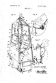
- FIG. 1 is a perspective view of the device suspended above the ground for use as a vantage point or protected enclosure.
- FIG. 2 is a perspective view of the device supported in a horizontal position for use as a hammock.
- FIG. 3 is an enlarged cutaway perspective view of the device showing the details of construction.
- FIG. 4 is an enlarged cutaway perspective of one of the upper corners of the device showing the rolled up flap and other details of construction.
- FIG. 5 is a perspective view of the base of the device showing the hinge points and backpacking straps as well as the packing flaps.
- FIG. 6 is a perspective view of the device partially folded up into a backpack.
- FIG. 7 is a side elevational view partly in section of the device completely folded and carried on the back of a user.
- FIG. 8 is a perspective view of the device with outside decoration resembling that of a space capsule for use by children as a toy.
- the numeral 10 generally designates the enclosure.
- the enclosure is comprised of two main parts, the framework 12 and the tentlike covering 14 which covers the frame thereby producing the enclosure.
- the framework 12 hasa main suspension rope 1 6' which is fixed at one end to the four free ends of two main comer support ropes or lines 18, which extend under the enclosure, by a knot 20 or other such fastening means.
- a rigid upper brace 22 is substantially square in shape and has a hole 24 at the four comers thereof.
- the corner ropes 18 are threaded through the holes in the brace 22 thereby providing a spacer for the ropes and rigid support for the tentlike covering.
- Four knots 26 are tied in each of the corner ropes to support the brace 22 in the proper position.
- the links 28,28 are shorter than the links 30,30 and are mounted on the front and back of the comer ropes, while the longer links 30,30 are mounted on the sides thereof.
- the links have apertures in the ends thereof through which are threaded the comer ropes 18.
- a knot 32 is tied in each of the comer ropes at the same distance from the upper knots 26 to space the four links at the proper height.
- the four links being thus disposed to extend and brace the corner ropes 18, while providing a framework on which to support a sling seat 34.
- the sling seat 34 has a main web 36 that is attached to the side links 30,30 and a rear web 38 which is mounted at one end to the rear link 28 and at the free end thereof is attached to the midpoint of the main web 36.
- a bottom or floor assembly 40 lies in a plane parallel to the planes determined by the links 28,28 and 30,30 and the plane defined by the rigid upper brace 22.
- the floor assembly 49 compriser a large front floor section 42 and a smaller rear floor section 44, and the two sections being hinged together along a common side 45 by the hinges 46.
- the hinges are located on the underside of the sections and when opened out the sections form a rectangle.
- a hole 48 is located adjacent each corner thereof, and an externally extending loop 50 is located at each corner of the assembly.
- the corner ropes 18 then extend downwardly from the knots 32 and through the holes in the floor assembly 48.
- the two forward corner ropes 18 form a loop under the front edge of the front floor section 42 and are protected from chafing and wear by a U-shaped channel section 52 which extends across the width of the floor assembly between the holes 48.
- the rear two comer ropes form a loop under the rear edge of the rear floor section 44 of the floor assembly and are similarly protected by a channel 52 thereon. Since the hinges 46 are on the underside of the floor assembly, 'any weight placed on the top of the floor assembly would further rigidify the floor assembly and would not c-ollapse it. This arrangement of the hinge and floor sections 42 and 44 permits a large rectangular floor area when the enclosure is in use and permits the floor assembly to fold into a smaller area for back packing or storage.
- the packing apparatus 58 is attached to the underside of the rigid base or floor assembly. At the front edge of the floor section 42 a large flap 60 is attached across the width thereof inside of the channel 52 and the rope ladder 56. A flap 62 of the same size and configuration as the front flap 60 is attached to the rear of the floor assembly along the edge of floor section 44 also within the U-shaped channel 52 attached thereto. Two side flaps 64 are attached along the sides of floor detachable 42 from the hinge point to the front edge thereof. Four packing straps 66 are attached to the floor assembly in spaced relation, one pair behind each side flap 64 along the side of the front floor section 42.
- each opposed pair of straps has a buckle 68 thereon to facilitate the strapping down of the collapsed enclosure and other supplies that may be desired to be attached to the folded floor assembly.
- a shoulder harness 70 is attached to the underside of section 42 of the floor assembly, and comprises two pair of straps 72 extending in parallel relationship to the long sides of the section 42 and adapted to receive the arms of the person carrying it therethrough.
- a large weighted book 74 is mounted on the end of the suspension rope 16 to provide a convenient means to throw the rope over the limb of a tree and form a loop around the trunk of a tree, as shown in FIG. 1.
- the tentlike covering 14 is adapted to slip over the framework 12.
- the top of the tentlike structure is composed of four equal triangular panels or sections 76. Since the rigid upper brace 22 is square in cross section the panels 76 form a pyramidlike structure with their angular seams meeting along the ropes 18 and their lower edges coinciding with the brace 22.
- a front panel or section 78 of the tentlike structure is adapted to be attached to the lower edge of a panel 76 and extend downward to the rigid platform.
- a zipper 80 is attached to the middle. of the front panel 78 and extends from a point slightly above the front link 28 down to the lower edge of the panel so that when opened it provide easy access into the interior of the enclosure for a person climbing up the ladder 56.
- the lower edge of the panel 78 has a loop 79 sewn therein on each side of the zipper whose function will be described hereinafter.
- a long zipper 82 is arranged in a U-shape to begin at the upper edge of the panel 78 and run parallel to the edge thereof and extend across the width of the section slightly above the end of zipper 82 and then up the opposite edge of the panel 78 to terminate at a point parallel to the original point of the zipper.
- the zipper 82 thus forms a U-shaped flap 84 on the upper half of the front panel 78.
- the flap 84 has a window 86 on the lower half thereof which may have a screened insert so that the window may be opened from the inside and air allowed to circulate therethrough without insects being permitted into the interior.
- a strap 88 is attached near the upper edge of the front section 78, its attaching point being parallel to the ends of the zipper 82, and the strap hangs down in parallel relation to the sides of the zipper.
- a rear panel or section 90 of the tentlike structure is substantially the same in size as the front panel 78 and is similarly attached to the lower edge of a triangular panel 76.
- the only difference between the front panel 78 and the rear panel 90 is that there is no need for the zipper on the rear panel.
- the lower edge of the panel 90 adjacent the rigid platform 40 is hemmed so as to form a closed loop therealong.
- a side panel or section 92 of the tentlike structure is adapted at its upper edge to attach to a lower edge of a triangular section 76 and extend downwardly to a lower edge adjacent the rigid platform 40, with the side edges thereof attached on one side to the front section 78 and on the opposite side to be connected to the rear section 90.
- the side section 92 has an elongated zipper 94 which begins at a point near the upper edge of the section and extends parallel to a side thereof to a point adjacent the lower edge of the flap 86 on the front section 78, where the zipper then extends across the section 92 and upward along the opposite side thereof to a point where it ends adjacent the beginning of the zipper.
- the zipper 94 thus forms a U-shaped flap 96 similar to the flaps in the front and rear sections.
- a window 98 is located in the lower portion of flap 96 and is held therein by a zipper 100.
- a screened insert is normally provided in such windows in tents so that the window may be lowered into the interior of the tent with the screened insert left therein to prevent insects from getting in.
- the lower edge of the section 92 is hemmed to form a closed loop 102 like the loop along the lower edge of the front section 78 and the rear section 90.
- a strap 104 is attached in the same relative position as the strap 88 on the front section 78 and is attached at its upper edge near the end of the zipper 94.
- the flap 96 can be rolled upwardly and the strap 104 extended around the roll and fastened on the interior of the tent between the upper brace 22 and the section 92. While one side section 92 has been described it is understood that the two side sections are identical. Having thus been described, the tentlike structure is shown as providing an outline substantially conforming to the outline of the supporting framework.
- the lower edges of the front section 78 and the two side sections 92 and the rear section have a loop thereon forming a loop along the lower edges of the four sides thereof.
- a rope 106 is threaded through this loop, and the rope is used as a drawstring so that when the tentlike structure is arranged over the frame the loop with the rope therein extends just below the surface of the rigid floor assembly 40, and when the drawstring or rope 106 is pulled tightly the tentlike structure will be attached thereon.
- a rubber rain stop 108 is provided on the top of the enclosure.
- the rubber rain stop 108 is conicalshaped with a hole 110 through the apex thereof which is smaller in circumference than the thickness of the main suspension rope l6.
- auxiliary ropes 112 are attached to the external eyelets 50 at the exterior comers of the rigid floor assembly 40 to aid in the maintaining of the enclosure in a stable condition when it is erected for use.
- FIG. 1 the enclosure is shown suspended by the main suspension rope 16 mounted over the limb of a tree and fastened to the trunk to raise the enclosure off the ground.
- the four auxiliary ropes 112 are stretched radially outward from the base to maintain the enclosure in a steady position.
- the ladder is then extended to the ground to provide access to the enclosure.
- the enclosure provides an elevated vantage point or could serve to get above damp or marshy ground, or provide safety from marauding animals.
- a second mounting position is possible in this configuration.
- the rope can be allowed to slip over the branch until the rigid floor section of the enclosure is in contact with the ground. In this position the enclosure is much like that of an ordinary tent. In this configuration, however, the guy ropes 112 would be stretched out along the surface of the ground to maintain the enclosure in a stable position, while the tension on the main support rope 16 would be maintained to hold the framework in an erected position.
- FIG. 2 A third mounting position is shown in FIG. 2 wherein the enclosure is used as a hammock with full protection being afforded therein from mosquitoes or the elements, much like a jungle tent.
- the main support rope 16 is secured to the trunk of one tree while the auxiliary ropes 112 on the front surface of the enclosure are attached in spaced relation on one tree and the auxiliary ropes 112 on the rear of the enclosure are attached to another tree in spaced relation.
- the side link 30 which would now be orientated on the lower surface of the hammock, is removed or slid upward on the comer ropes 18 so as tqbe out of the way of a person reclining on the side section 92 of the hammock.
- the zipper 80 when opened, provides easy access into and out of the enclosure in this hammock mounting position.
- the folding of the enclosure for back packing or storage thereof can be readily is folded by referring to FIG. 6.
- the main support rope 16 is detached from wherever mounted and the rigid floor assembly 40 is folded with the section 44 thereof being folded under the section 42 and laid on the or other articles usually carried by a person utilizing this device may then be deposited on the top of the pile.
- the front and rear flaps, 60 and 62 respectively,,and the sidetflaps 64 are then folded upwardly over the pile created therebetween.
- the packing straps 66 are, then engaged and firmly drawn down tightly thereon. This creates a tight bundle or pack as isshown in FIG. 7.
- the enclosure has been-disclosed as a vantage point for sportsmen or hammock to be usedoutldoors, it can readily be seen from the configuration inFlG. 8 that the enclosure has great meritas a toy or amusement device for children.
- the structure remains basically the same except that suitable indicia or designs would be applied to the four sides of r the tentlike structure.
- the four flaps that hang down from the rigid floor assembly could be configured to representflamessuch as would be the exhaust ofa rocket.
- the device as configured could be mounted in anyone of the three aforementioned positions to be utilized by childrenrepresenting in the second position mentioned above arocket shortly before launching.
- the first position mentioned above would represent the rocket shortly after blastoff, while the third or hammock position mentioned above could represent the rocket in flight.
- the device would be utilized by childrenas'a tree house, tent on the ground, or hammock tosleep in.
- the various uses of such a configuration would be limited only by the imagination of h enclosure may be expanded or contracted as the needs of the user require by simple and obvious modification of the basic structure disclosed herein.
- a suspendedenclosure comprising: a base member, a collapsible frame assembly attached to said base member, suspension means to suspend said frame assemblyfrom an outside object, a flexible cover to enclose the space defined by rigid angular platform, said frame assembly comprising-first v and second elongated flexible members engaging the platform at their midpoint with the free ends thereof joined together to form a suspension point, and including a; rigid brace adapted to, engage and spreadthe elongated flexible members near the free ends thereof, said frame assembly further including a link assembly adapted to engage and spread the eiongated flexible members between the platform and the rigid brace, said link assembly including a flexible seat suspended therefrom.
- each panel has a zippered closure therein and means to hold said closure in an open position.
- a suspended enclosure comprising: a base member, a collapsible frame assembly attached to i said base member, suspension means to suspend said frame assembly from an outside object, a flexible cover to enclose the space defined by the base member and the frame assembly, said base member comprising first and secondsections hinged together to form a rigid rectangular platform, said platform having packing means attached to the underside thereof to enable the enclosure, when collapsed to be secured.
- said packing means including flexible flaps fixed along the three sides of said first section forming a portion of the periphery of saidplatform, a flexible flap I fixed along the side of said second section remote from said the base member and the frame assembly, saidbase member comprising first and second sections hinged together to form a downwardly opening cover closed at its upper end and draped hinge point, and cooperating fastening means fixed along the sides of the first section adjacent the hinge point thereof to fasten-said collapsed enclosure on said first section.
- a suspended enclosure comprising a lower horizontal base platform, an upper horizontal frame spaced vertically above said platformand suspended from said support member, a plurality of upstanding elongated flexible suspension members having the upper ends thereof anchored to peripherally spaced portions of said platform in elevated position from said support member, a i
- suspension members being free of direct connection with said cover.
Landscapes
- Engineering & Computer Science (AREA)
- Architecture (AREA)
- Civil Engineering (AREA)
- Structural Engineering (AREA)
- Tents Or Canopies (AREA)
Description
mama m mm 3545461 SHEET 1 OF 3 I BY @Mm PATENTEU DEC 8 I970 SHEET 2 OF 3 Fig. 3
INVENTOR.
TREE SUSPENDED ENCLOSURE I-Ieretofore shelters that sportsmen could carry on their backs were limited to small tents that were pitched on the ground. In order to insulate against the coldness of the ground or dampness from rain, etc. heavy waterproof insulating ground cloths were required to be carried along with the portable closure. Also, such tents would not readily lend themselves to use as a blind or similar protection.
The present inventionrelates to a collapsible tentlike structure that is means to be supported in three positions. The first position would be in an upright position suspended from a tree limb or other point above the surface of the ground. When thus suspended it provides a shelter free of ground conditions or marauding animals for a sportsman. A second position of support would be in an upright position resting on the ground. When in this position it could serve as a duck blind or other shelter from the elements for use by a person seated therein. A third position would be supported horizontally between a number of trees or other vertical supports wherein the flexible tentlike structure could then serve as a hammock providing protection from insects and rain. The device folds compactly onto its supporting base and is strapped thereto so that it may be. carried on the back of the user. Thus the shelter is extremely portable and can be carried by a hunter or hiker. When car ried on the back of the sportsman other supplies may be enclosed within the flaps so as to provide a single carrying device for both the shelter and such supplies. The device also readily lends itself to use as a toy-by children, since in its supported position on takeoff, it would represent a rocket prior to launch and in its suspended position above the ground it would simulate a rocket shortly after takeoff, and similarly the horizontal position could represent the rocket in flight. A simple change in the exterior decoration of the tent to simulate a rocket would enhance the appeal of the device as such a toy.
It is therefore an object of this invention to provide a simple but unique portable enclosure for sportsmen.
It is a further'object of this invention to provide a portable enclosure to protect sportsmen that can be easily transported by the user.
It is a further object of this invention to provide a portable enclosure for sportsmen that can be supported above the ground to protect the user from undesirable ground conditions.
It is a further object of this invention to provide a portable enclosure that can be supported on the ground for use as a duck blind. i
It is a further object of this invention to provide a portable enclosure for sportsmen that can be utilized as a hammock to protect the user from the elements and insects.
It is a still further object of this invention to provide a portable enclosure for sportsmen that can be utilized as a container for supplies when carried on the back.
These together with other objects and advantages which will become subsequently apparent reside in the details of construction and operation as more fully hereinafter described and claimed, reference being had to the accompanying drawings forming a part hereof, wherein like numerals refer to like parts throughout, and in which:
FIG. 1 is a perspective view of the device suspended above the ground for use as a vantage point or protected enclosure.
FIG. 2 is a perspective view of the device supported in a horizontal position for use as a hammock.
FIG. 3 is an enlarged cutaway perspective view of the device showing the details of construction.
FIG. 4 is an enlarged cutaway perspective of one of the upper corners of the device showing the rolled up flap and other details of construction.
FIG. 5 is a perspective view of the base of the device showing the hinge points and backpacking straps as well as the packing flaps.
FIG. 6 is a perspective view of the device partially folded up into a backpack.
FIG. 7 is a side elevational view partly in section of the device completely folded and carried on the back of a user.
FIG. 8 is a perspective view of the device with outside decoration resembling that of a space capsule for use by children as a toy.
Referring now to the drawings, the numeral 10 generally designates the enclosure. The enclosure is comprised of two main parts, the framework 12 and the tentlike covering 14 which covers the frame thereby producing the enclosure. The framework 12 hasa main suspension rope 1 6' which is fixed at one end to the four free ends of two main comer support ropes or lines 18, which extend under the enclosure, by a knot 20 or other such fastening means. A rigid upper brace 22 is substantially square in shape and has a hole 24 at the four comers thereof. The corner ropes 18 are threaded through the holes in the brace 22 thereby providing a spacer for the ropes and rigid support for the tentlike covering. Four knots 26 are tied in each of the corner ropes to support the brace 22 in the proper position. Also mounted on the comer ropes are two pairs of spacer links 28,28 and30,30. The links 28,28 are shorter than the links 30,30 and are mounted on the front and back of the comer ropes, while the longer links 30,30 are mounted on the sides thereof. The links have apertures in the ends thereof through which are threaded the comer ropes 18. A knot 32 is tied in each of the comer ropes at the same distance from the upper knots 26 to space the four links at the proper height. The four links being thus disposed to extend and brace the corner ropes 18, while providing a framework on which to support a sling seat 34. The sling seat 34 has a main web 36 that is attached to the side links 30,30 and a rear web 38 which is mounted at one end to the rear link 28 and at the free end thereof is attached to the midpoint of the main web 36.
A bottom or floor assembly 40 lies in a plane parallel to the planes determined by the links 28,28 and 30,30 and the plane defined by the rigid upper brace 22. The floor assembly 49 compriser a large front floor section 42 and a smaller rear floor section 44, and the two sections being hinged together along a common side 45 by the hinges 46. The hinges are located on the underside of the sections and when opened out the sections form a rectangle. With the floor sections 42 and 44 opened out to form the rectangular floor assembly, a hole 48 is located adjacent each corner thereof, and an externally extending loop 50 is located at each corner of the assembly. The corner ropes 18 then extend downwardly from the knots 32 and through the holes in the floor assembly 48. The two forward corner ropes 18 form a loop under the front edge of the front floor section 42 and are protected from chafing and wear by a U-shaped channel section 52 which extends across the width of the floor assembly between the holes 48. Similarly, the rear two comer ropes form a loop under the rear edge of the rear floor section 44 of the floor assembly and are similarly protected by a channel 52 thereon. Since the hinges 46 are on the underside of the floor assembly, 'any weight placed on the top of the floor assembly would further rigidify the floor assembly and would not c-ollapse it. This arrangement of the hinge and floor sections 42 and 44 permits a large rectangular floor area when the enclosure is in use and permits the floor assembly to fold into a smaller area for back packing or storage. There are two holes 54 drilled through the front edge of the floor section 42 spaced inwardly of the holes 48 along the front edge thereof, for the attachment of a rope ladder 56 to provide access to the enclosure when it is suspended abovethe ground. The rope ladder 56 thereby provides access for the enclosure when suspended without the need to carry any other climbing apparatus and could be detachable therefrom to be used for other situations.
The packing apparatus 58 is attached to the underside of the rigid base or floor assembly. At the front edge of the floor section 42 a large flap 60 is attached across the width thereof inside of the channel 52 and the rope ladder 56. A flap 62 of the same size and configuration as the front flap 60 is attached to the rear of the floor assembly along the edge of floor section 44 also within the U-shaped channel 52 attached thereto. Two side flaps 64 are attached along the sides of floor detachable 42 from the hinge point to the front edge thereof. Four packing straps 66 are attached to the floor assembly in spaced relation, one pair behind each side flap 64 along the side of the front floor section 42. One end of each opposed pair of straps has a buckle 68 thereon to facilitate the strapping down of the collapsed enclosure and other supplies that may be desired to be attached to the folded floor assembly. A shoulder harness 70 is attached to the underside of section 42 of the floor assembly, and comprises two pair of straps 72 extending in parallel relationship to the long sides of the section 42 and adapted to receive the arms of the person carrying it therethrough. As thus described it can be seen that when the framework 12 is suspended from a tree by the main suspension rope 16 the framework 22, the links 28,28 and 30,30, and the rigid floor assembly 40 stretch the corner ropes 18 into rigid support members for the tentlike structure that is draped over the framework. To facilitate erecting the enclosure, a large weighted book 74 is mounted on the end of the suspension rope 16 to provide a convenient means to throw the rope over the limb of a tree and form a loop around the trunk of a tree, as shown in FIG. 1.
The tentlike covering 14 is adapted to slip over the framework 12. The top of the tentlike structure is composed of four equal triangular panels or sections 76. Since the rigid upper brace 22 is square in cross section the panels 76 form a pyramidlike structure with their angular seams meeting along the ropes 18 and their lower edges coinciding with the brace 22. A front panel or section 78 of the tentlike structure is adapted to be attached to the lower edge of a panel 76 and extend downward to the rigid platform. A zipper 80 is attached to the middle. of the front panel 78 and extends from a point slightly above the front link 28 down to the lower edge of the panel so that when opened it provide easy access into the interior of the enclosure for a person climbing up the ladder 56. The lower edge of the panel 78 has a loop 79 sewn therein on each side of the zipper whose function will be described hereinafter. A long zipper 82 is arranged in a U-shape to begin at the upper edge of the panel 78 and run parallel to the edge thereof and extend across the width of the section slightly above the end of zipper 82 and then up the opposite edge of the panel 78 to terminate at a point parallel to the original point of the zipper. The zipper 82 thus forms a U-shaped flap 84 on the upper half of the front panel 78. The flap 84 has a window 86 on the lower half thereof which may have a screened insert so that the window may be opened from the inside and air allowed to circulate therethrough without insects being permitted into the interior.- A strap 88 is attached near the upper edge of the front section 78, its attaching point being parallel to the ends of the zipper 82, and the strap hangs down in parallel relation to the sides of the zipper. Thus, when the zipper 82 is open the flap 84 can be rolled upwardly and the strap 88 extended outwardly around the roll and then tucked inwardly between the inside of the panel 78 and cross brace 22 to hold the flap 84 in its rolled up configuration. This is shown in detail in FIG. 4. A rear panel or section 90 of the tentlike structure is substantially the same in size as the front panel 78 and is similarly attached to the lower edge of a triangular panel 76. The only difference between the front panel 78 and the rear panel 90 is that there is no need for the zipper on the rear panel. Also, the lower edge of the panel 90 adjacent the rigid platform 40 is hemmed so as to form a closed loop therealong. A side panel or section 92 of the tentlike structure is adapted at its upper edge to attach to a lower edge of a triangular section 76 and extend downwardly to a lower edge adjacent the rigid platform 40, with the side edges thereof attached on one side to the front section 78 and on the opposite side to be connected to the rear section 90. The side section 92 has an elongated zipper 94 which begins at a point near the upper edge of the section and extends parallel to a side thereof to a point adjacent the lower edge of the flap 86 on the front section 78, where the zipper then extends across the section 92 and upward along the opposite side thereof to a point where it ends adjacent the beginning of the zipper. The zipper 94 thus forms a U-shaped flap 96 similar to the flaps in the front and rear sections. A window 98 is located in the lower portion of flap 96 and is held therein by a zipper 100. A screened insert is normally provided in such windows in tents so that the window may be lowered into the interior of the tent with the screened insert left therein to prevent insects from getting in. The lower edge of the section 92 is hemmed to form a closed loop 102 like the loop along the lower edge of the front section 78 and the rear section 90. A strap 104 is attached in the same relative position as the strap 88 on the front section 78 and is attached at its upper edge near the end of the zipper 94. Thus, the flap 96 can be rolled upwardly and the strap 104 extended around the roll and fastened on the interior of the tent between the upper brace 22 and the section 92. While one side section 92 has been described it is understood that the two side sections are identical. Having thus been described, the tentlike structure is shown as providing an outline substantially conforming to the outline of the supporting framework. The lower edges of the front section 78 and the two side sections 92 and the rear section have a loop thereon forming a loop along the lower edges of the four sides thereof. A rope 106 is threaded through this loop, and the rope is used as a drawstring so that when the tentlike structure is arranged over the frame the loop with the rope therein extends just below the surface of the rigid floor assembly 40, and when the drawstring or rope 106 is pulled tightly the tentlike structure will be attached thereon. To provide a completely waterproof interior, a rubber rain stop 108 is provided on the top of the enclosure. The rubber rain stop 108 is conicalshaped with a hole 110 through the apex thereof which is smaller in circumference than the thickness of the main suspension rope l6. Thereby, when the rain stop is slipped over the rope 16 into place at the apex of the four sides 76 the rope will be sealingly engaged in the hole 110 and the rain will be prevented from entering the apex of the flaps 76 where the rope 16 enters therein.
Four auxiliary ropes 112 are attached to the external eyelets 50 at the exterior comers of the rigid floor assembly 40 to aid in the maintaining of the enclosure in a stable condition when it is erected for use. In FIG. 1 the enclosure is shown suspended by the main suspension rope 16 mounted over the limb of a tree and fastened to the trunk to raise the enclosure off the ground. The four auxiliary ropes 112 are stretched radially outward from the base to maintain the enclosure in a steady position. The ladder is then extended to the ground to provide access to the enclosure. Thus mounted the enclosure provides an elevated vantage point or could serve to get above damp or marshy ground, or provide safety from marauding animals. A second mounting position is possible in this configuration. The rope can be allowed to slip over the branch until the rigid floor section of the enclosure is in contact with the ground. In this position the enclosure is much like that of an ordinary tent. In this configuration, however, the guy ropes 112 would be stretched out along the surface of the ground to maintain the enclosure in a stable position, while the tension on the main support rope 16 would be maintained to hold the framework in an erected position. A third mounting position is shown in FIG. 2 wherein the enclosure is used as a hammock with full protection being afforded therein from mosquitoes or the elements, much like a jungle tent. In this mounting position the main support rope 16 is secured to the trunk of one tree while the auxiliary ropes 112 on the front surface of the enclosure are attached in spaced relation on one tree and the auxiliary ropes 112 on the rear of the enclosure are attached to another tree in spaced relation. This being accomplished, the side link 30 which would now be orientated on the lower surface of the hammock, is removed or slid upward on the comer ropes 18 so as tqbe out of the way of a person reclining on the side section 92 of the hammock. Similarly, the zipper 80 when opened, provides easy access into and out of the enclosure in this hammock mounting position.
The folding of the enclosure for back packing or storage thereof can be readily is folded by referring to FIG. 6. The main support rope 16 is detached from wherever mounted and the rigid floor assembly 40 is folded with the section 44 thereof being folded under the section 42 and laid on the or other articles usually carried by a person utilizing this device may then be deposited on the top of the pile. With everything desired to be enclosed thereon the front and rear flaps, 60 and 62 respectively,,and the sidetflaps 64 are then folded upwardly over the pile created therebetween. When the four flaps have'been overlapped on the top of the pile the packing straps 66 are, then engaged and firmly drawn down tightly thereon. This creates a tight bundle or pack as isshown in FIG. 7. With the pack thus firmly tied together the user can suspend it from his shoulders by means of the pair of packing straps 70. From the procedure in packing the enclosure, it can readily be seen the ease and simplicity oferecting the enclosure when it is. desired to be used. The reverse procedure would be followed, that is, the straps 66 would be unbuckled and laid out flat on the ground, and the four flaps would then cles that have been packed thereon wouldthen be removed and the main support rope 16 would be thrown over a limb by means of the heavy weighted book 74. The ropewould then be drawn, upwardly until the structure had erected itself by means of the inner framework 12. The rope 16 would then be secured to the trunk of a tree with the enclosure suspended at whatever height desired. The tightening of the drawstring 106 and the securing of the ropes 112 would then complete the installation.
While the enclosure has been-disclosed as a vantage point for sportsmen or hammock to be usedoutldoors, it can readily be seen from the configuration inFlG. 8 that the enclosure has great meritas a toy or amusement device for children. As seen therein, the structure remains basically the same except that suitable indicia or designs would be applied to the four sides of r the tentlike structure. Similarly,,if desired, the four flaps that hang down from the rigid floor assembly could be configured to representflamessuch as would be the exhaust ofa rocket.
The device as configured could be mounted in anyone of the three aforementioned positions to be utilized by childrenrepresenting in the second position mentioned above arocket shortly before launching. The first position mentioned above would represent the rocket shortly after blastoff, while the third or hammock position mentioned above could represent the rocket in flight. Further, it can readily be seen that the device would be utilized by childrenas'a tree house, tent on the ground, or hammock tosleep in. The various uses of such a configuration would be limited only by the imagination of h enclosure may be expanded or contracted as the needs of the user require by simple and obvious modification of the basic structure disclosed herein.
The foregoing is considered as illustrative-only of the princii ples of the invention. Further, since numerous modifications and changes will readily occur to those skilled in the art, it is not desired to limit the invention to the exact construction and operation shown and described, and accordingly all suitable modifications and equivalents may be resorted to, falling within the scope of the invention.
I claim: 1
1. A suspendedenclosure, comprising: a base member, a collapsible frame assembly attached to said base member, suspension means to suspend said frame assemblyfrom an outside object, a flexible cover to enclose the space defined by rigid angular platform, said frame assembly comprising-first v and second elongated flexible members engaging the platform at their midpoint with the free ends thereof joined together to form a suspension point, and including a; rigid brace adapted to, engage and spreadthe elongated flexible members near the free ends thereof, said frame assembly further including a link assembly adapted to engage and spread the eiongated flexible members between the platform and the rigid brace, said link assembly including a flexible seat suspended therefrom.
2. The device of claim 1 whereinsaid flexible cover includes four panels joined together with the lower edge of each side corresponding to a side of the platform. i
3. The device of claim 2 wherein the panel corresponding to the side of said first section remotefrom said hinge has a zipperedentrance therethrough.
4. The device of claim 3 wherein said panels have a loop along the lower edge thereof with an elongated flexible member received therein to relatively shorten the perimeter defined by the lower edges of said panels undersaid platform and thereby attach said flexible cover to the platform.
5. The device of claim 4 wherein each panel has a zippered closure therein and means to hold said closure in an open position.
means attached to the underside thereof to enable the enclosure when collapsed to be secured to said platform for storage and transporting.
7. .A suspended enclosure, comprising: a base member, a collapsible frame assembly attached to i said base member, suspension means to suspend said frame assembly from an outside object, a flexible cover to enclose the space defined by the base member and the frame assembly, said base member comprising first and secondsections hinged together to form a rigid rectangular platform, said platform having packing means attached to the underside thereof to enable the enclosure, when collapsed to be secured. to said platform for storage and transporting, said packing means including flexible flaps fixed along the three sides of said first section forming a portion of the periphery of saidplatform, a flexible flap I fixed along the side of said second section remote from said the base member and the frame assembly, saidbase member comprising first and second sections hinged together to form a downwardly opening cover closed at its upper end and draped hinge point, and cooperating fastening means fixed along the sides of the first section adjacent the hinge point thereof to fasten-said collapsed enclosure on said first section.
8. The deviceof claim 7 wherein said fastening means are belts. i i i a r 9. The device of claim 7 wherein said packing means, includes a harness on the underside of said first section to allow the collapsed enclosure to be suspended fromaperson.
10. The combination of claim 7 wherein the frame assembly comprises first and second elongated flexible members engaging the platform at their midpoints with the free ends thereof joined together to form a suspension point. i
11. The combination of claim-16-wherein the frame assembly includes a rigid brace adapted to engage and spread the elongated flexiblemembers near the free ends thereof.
and the rigid brace.
13. In combination with a support member, a suspended enclosure comprising a lower horizontal base platform, an upper horizontal frame spaced vertically above said platformand suspended from said support member, a plurality of upstanding elongated flexible suspension members having the upper ends thereof anchored to peripherally spaced portions of said platform in elevated position from said support member, a i
6. The device of claim 1 wherein said platform has packing 8 the closed upper end of said cover overlying said frame, said.
suspension members being free of direct connection with said cover.
Applications Claiming Priority (1)
| Application Number | Priority Date | Filing Date | Title |
|---|---|---|---|
| US75402668A | 1968-08-20 | 1968-08-20 |
Publications (1)
| Publication Number | Publication Date |
|---|---|
| US3545461A true US3545461A (en) | 1970-12-08 |
Family
ID=25033179
Family Applications (1)
| Application Number | Title | Priority Date | Filing Date |
|---|---|---|---|
| US754026A Expired - Lifetime US3545461A (en) | 1968-08-20 | 1968-08-20 | Tree suspended enclosure |
Country Status (1)
| Country | Link |
|---|---|
| US (1) | US3545461A (en) |
Cited By (42)
| Publication number | Priority date | Publication date | Assignee | Title |
|---|---|---|---|---|
| US3690334A (en) * | 1970-11-16 | 1972-09-12 | Herbert Boyd Miller | Portable hunting blind |
| US3880459A (en) * | 1973-02-22 | 1975-04-29 | Robert A Kelley | Tent enclosure |
| US4057859A (en) * | 1975-11-11 | 1977-11-15 | Setterholm Jeffrey M | Suspendible sleeping surface and tent |
| US4526307A (en) * | 1984-07-06 | 1985-07-02 | Parker Ronald J | Portable combination tent and backpack |
| US4612948A (en) * | 1984-12-24 | 1986-09-23 | Insta-Hut Inc. | Portable shelter or tent enclosure, structures and components therefor |
| US5479744A (en) * | 1994-06-01 | 1996-01-02 | Meyer; Scott A. | Movable utility greenhouse |
| USD397756S (en) | 1997-03-07 | 1998-09-01 | Tammy Lynn Hagerty | Toy playhouse |
| US6062446A (en) * | 1991-10-18 | 2000-05-16 | Academy Of Applied Science | Combined backpack, cot and tent |
| US6220264B1 (en) * | 1997-03-10 | 2001-04-24 | Terrelogic, Inc. | Suspension tent |
| DE10000764A1 (en) * | 2000-01-11 | 2001-07-26 | Fritz Riegel | Tent especially for mountaineering with pyramid shaped cover with one side wall steeper than remaining side walls and provided with access opening |
| US6338356B1 (en) * | 2000-05-02 | 2002-01-15 | Dalaimour Wallenstatter | Portable tent |
| US20030172965A1 (en) * | 2002-03-18 | 2003-09-18 | Mark Norris | Cover support device for pole |
| FR2841451A1 (en) * | 2002-06-28 | 2004-01-02 | Jean Paul Scherrer | Structural volume with wire frame comprising series of cables supporting canvas |
| US20040255526A1 (en) * | 2003-06-20 | 2004-12-23 | Tremblay Michel J. | Foldable shelter |
| US7219680B1 (en) * | 2003-03-29 | 2007-05-22 | Gresock Alex S | Backpack hunting blind |
| US20070119490A1 (en) * | 2005-11-28 | 2007-05-31 | Reddick Stephen M | Hunting blind |
| US20070145089A1 (en) * | 2005-12-27 | 2007-06-28 | Blacks Creek Guide Gear Inc. | Backpack device configured for carrying oversized cargo comfortably |
| US20080295877A1 (en) * | 2007-05-30 | 2008-12-04 | Wright Clifton P | Portable tree mounted hunting blind |
| US20090184544A1 (en) * | 2004-11-18 | 2009-07-23 | Sunbathing Mama's Llc | Attachable swing shade |
| US20090229917A1 (en) * | 2008-03-12 | 2009-09-17 | Berkbuegler Ronald L | Tree Stand |
| US20100252083A1 (en) * | 2007-09-13 | 2010-10-07 | Live Life Outdoors International Limited | Suspendable tent |
| US20110079259A1 (en) * | 2009-10-07 | 2011-04-07 | Kristina Main | Covering apparatus or tent for a platform swing |
| USD637738S1 (en) | 2006-09-19 | 2011-05-10 | Stephen Michael Reddick | Hunting blind |
| US8695859B1 (en) * | 2009-12-21 | 2014-04-15 | Alan Stalker | Frameless hunting blind contained in a fanny pack or backpack |
| US8776814B1 (en) * | 2011-08-10 | 2014-07-15 | Primos, Inc. | Window adjustment system for blinds |
| US20140299638A1 (en) * | 2012-02-10 | 2014-10-09 | Tamera M. Church | Trilitary pac a backpack, hammock & tent |
| US20150020857A1 (en) * | 2013-07-16 | 2015-01-22 | Eripio, Llc | Shelter lift attachment for a portable human transport system |
| US9254446B2 (en) | 2013-07-03 | 2016-02-09 | Plow & Hearth, Llc | Suspended play structure |
| US9316018B2 (en) * | 2014-08-23 | 2016-04-19 | Vaios Bozikis | Suspended dwelling |
| CN105525768A (en) * | 2015-11-26 | 2016-04-27 | 陈健玲 | Trinity hanging house |
| EP3024991A4 (en) * | 2013-07-24 | 2017-03-01 | Richard J. Duncan | Hanging structures having zome geometry |
| US9630119B2 (en) | 2013-07-03 | 2017-04-25 | Plow & Hearth, Llc | Suspended play structure |
| US9631395B1 (en) * | 2014-10-09 | 2017-04-25 | Mihail Angelov Todorov | Multifunctional outdoor shelter system with variably attachable hooded garment floor and canopy |
| US20170234025A1 (en) * | 2016-02-11 | 2017-08-17 | Ricardo Bottome | Treepod Assembly |
| US20170314288A1 (en) * | 2016-04-28 | 2017-11-02 | Sky-Pod World Ltd. | Suspendable structure |
| US9903135B1 (en) | 2014-10-09 | 2018-02-27 | Mihail Angelov Todorov | Rainwear-shelter with attachable perimeters |
| USD827080S1 (en) * | 2017-02-10 | 2018-08-28 | Canaima Outdoors, Inc. | Hanging pod |
| USD831749S1 (en) | 2017-08-08 | 2018-10-23 | Canaima Outdoors, Inc. | Hanging tent structure |
| US10285397B2 (en) * | 2016-02-03 | 2019-05-14 | Erick Swanson | Tree stand/seat cover |
| USD902610S1 (en) * | 2020-06-04 | 2020-11-24 | Yuli Sun | Hammock |
| US20210404209A1 (en) * | 2020-06-30 | 2021-12-30 | Printed Answers, LLC | Corner bracket for portable enclosure |
| US20240341298A1 (en) * | 2023-03-23 | 2024-10-17 | Delaney LEWIS | Portable one-person hanging blind |
-
1968
- 1968-08-20 US US754026A patent/US3545461A/en not_active Expired - Lifetime
Cited By (50)
| Publication number | Priority date | Publication date | Assignee | Title |
|---|---|---|---|---|
| US3690334A (en) * | 1970-11-16 | 1972-09-12 | Herbert Boyd Miller | Portable hunting blind |
| US3880459A (en) * | 1973-02-22 | 1975-04-29 | Robert A Kelley | Tent enclosure |
| US4057859A (en) * | 1975-11-11 | 1977-11-15 | Setterholm Jeffrey M | Suspendible sleeping surface and tent |
| US4526307A (en) * | 1984-07-06 | 1985-07-02 | Parker Ronald J | Portable combination tent and backpack |
| US4612948A (en) * | 1984-12-24 | 1986-09-23 | Insta-Hut Inc. | Portable shelter or tent enclosure, structures and components therefor |
| US6062446A (en) * | 1991-10-18 | 2000-05-16 | Academy Of Applied Science | Combined backpack, cot and tent |
| US5479744A (en) * | 1994-06-01 | 1996-01-02 | Meyer; Scott A. | Movable utility greenhouse |
| USD397756S (en) | 1997-03-07 | 1998-09-01 | Tammy Lynn Hagerty | Toy playhouse |
| US6220264B1 (en) * | 1997-03-10 | 2001-04-24 | Terrelogic, Inc. | Suspension tent |
| DE10000764B4 (en) * | 2000-01-11 | 2005-03-17 | Fritz Riegel | Tent / bivy bag combination |
| DE10000764A1 (en) * | 2000-01-11 | 2001-07-26 | Fritz Riegel | Tent especially for mountaineering with pyramid shaped cover with one side wall steeper than remaining side walls and provided with access opening |
| US6338356B1 (en) * | 2000-05-02 | 2002-01-15 | Dalaimour Wallenstatter | Portable tent |
| US20030172965A1 (en) * | 2002-03-18 | 2003-09-18 | Mark Norris | Cover support device for pole |
| US7140375B2 (en) * | 2002-03-18 | 2006-11-28 | Mark Norris | Cover support device for pole |
| FR2841451A1 (en) * | 2002-06-28 | 2004-01-02 | Jean Paul Scherrer | Structural volume with wire frame comprising series of cables supporting canvas |
| US7219680B1 (en) * | 2003-03-29 | 2007-05-22 | Gresock Alex S | Backpack hunting blind |
| US20040255526A1 (en) * | 2003-06-20 | 2004-12-23 | Tremblay Michel J. | Foldable shelter |
| US20090184544A1 (en) * | 2004-11-18 | 2009-07-23 | Sunbathing Mama's Llc | Attachable swing shade |
| US20070119490A1 (en) * | 2005-11-28 | 2007-05-31 | Reddick Stephen M | Hunting blind |
| US20070145089A1 (en) * | 2005-12-27 | 2007-06-28 | Blacks Creek Guide Gear Inc. | Backpack device configured for carrying oversized cargo comfortably |
| USD637738S1 (en) | 2006-09-19 | 2011-05-10 | Stephen Michael Reddick | Hunting blind |
| US20080295877A1 (en) * | 2007-05-30 | 2008-12-04 | Wright Clifton P | Portable tree mounted hunting blind |
| US7556052B2 (en) | 2007-05-30 | 2009-07-07 | Paul Wright | Portable tree mounted hunting blind |
| US20100252083A1 (en) * | 2007-09-13 | 2010-10-07 | Live Life Outdoors International Limited | Suspendable tent |
| US20090229917A1 (en) * | 2008-03-12 | 2009-09-17 | Berkbuegler Ronald L | Tree Stand |
| US20110079259A1 (en) * | 2009-10-07 | 2011-04-07 | Kristina Main | Covering apparatus or tent for a platform swing |
| US8695859B1 (en) * | 2009-12-21 | 2014-04-15 | Alan Stalker | Frameless hunting blind contained in a fanny pack or backpack |
| US8776814B1 (en) * | 2011-08-10 | 2014-07-15 | Primos, Inc. | Window adjustment system for blinds |
| US20140299638A1 (en) * | 2012-02-10 | 2014-10-09 | Tamera M. Church | Trilitary pac a backpack, hammock & tent |
| US9254446B2 (en) | 2013-07-03 | 2016-02-09 | Plow & Hearth, Llc | Suspended play structure |
| US9630119B2 (en) | 2013-07-03 | 2017-04-25 | Plow & Hearth, Llc | Suspended play structure |
| US20150020857A1 (en) * | 2013-07-16 | 2015-01-22 | Eripio, Llc | Shelter lift attachment for a portable human transport system |
| US9347238B2 (en) * | 2013-07-16 | 2016-05-24 | Eripio, Llc | Shelter lift attachment for a portable human transport system |
| US9890554B2 (en) | 2013-07-24 | 2018-02-13 | Richard J. Duncan, Iii | Hanging structures having zome geometry |
| EP3024991A4 (en) * | 2013-07-24 | 2017-03-01 | Richard J. Duncan | Hanging structures having zome geometry |
| US9316018B2 (en) * | 2014-08-23 | 2016-04-19 | Vaios Bozikis | Suspended dwelling |
| US9631395B1 (en) * | 2014-10-09 | 2017-04-25 | Mihail Angelov Todorov | Multifunctional outdoor shelter system with variably attachable hooded garment floor and canopy |
| US9903135B1 (en) | 2014-10-09 | 2018-02-27 | Mihail Angelov Todorov | Rainwear-shelter with attachable perimeters |
| CN105525768A (en) * | 2015-11-26 | 2016-04-27 | 陈健玲 | Trinity hanging house |
| US10285397B2 (en) * | 2016-02-03 | 2019-05-14 | Erick Swanson | Tree stand/seat cover |
| US9988824B2 (en) * | 2016-02-11 | 2018-06-05 | Canaima Outdoors, Inc. | Treepod assembly |
| US20170234025A1 (en) * | 2016-02-11 | 2017-08-17 | Ricardo Bottome | Treepod Assembly |
| US20170314288A1 (en) * | 2016-04-28 | 2017-11-02 | Sky-Pod World Ltd. | Suspendable structure |
| USD827080S1 (en) * | 2017-02-10 | 2018-08-28 | Canaima Outdoors, Inc. | Hanging pod |
| USD831749S1 (en) | 2017-08-08 | 2018-10-23 | Canaima Outdoors, Inc. | Hanging tent structure |
| USD902610S1 (en) * | 2020-06-04 | 2020-11-24 | Yuli Sun | Hammock |
| US20210404209A1 (en) * | 2020-06-30 | 2021-12-30 | Printed Answers, LLC | Corner bracket for portable enclosure |
| US11585112B2 (en) * | 2020-06-30 | 2023-02-21 | Andrew Martinek | Corner bracket for portable enclosure |
| US20240341298A1 (en) * | 2023-03-23 | 2024-10-17 | Delaney LEWIS | Portable one-person hanging blind |
| US12607032B2 (en) * | 2023-03-23 | 2026-04-21 | Delaney LEWIS | Portable one-person hanging blind |
Similar Documents
| Publication | Publication Date | Title |
|---|---|---|
| US3545461A (en) | Tree suspended enclosure | |
| US5113537A (en) | Portable sleeping unit for children | |
| US4526307A (en) | Portable combination tent and backpack | |
| US5240021A (en) | Suspension tent | |
| US6021794A (en) | Portable collapsible shelter | |
| US4914768A (en) | Portable shelter | |
| US4723371A (en) | Self supported, collapsible, and portable walled structure suitable for use as a hunting blind | |
| US4838293A (en) | Tepee tent | |
| US5913772A (en) | Tent hammock | |
| US4632138A (en) | Portable shelter | |
| US4077418A (en) | Quickly erected back pack tent | |
| US6109281A (en) | Sunshade device | |
| US9788639B2 (en) | Protective hammock enclosure and method of use | |
| US8695859B1 (en) | Frameless hunting blind contained in a fanny pack or backpack | |
| US3699986A (en) | Modular shelter system | |
| US4269210A (en) | Arch supported tent | |
| US5642538A (en) | Self-erecting play yard structure | |
| US5906217A (en) | Collapsible bale blind | |
| US5769106A (en) | Convertible panel and shelter system | |
| US5277349A (en) | Combination backpack and tent | |
| US4686720A (en) | Covered hammock | |
| US2615458A (en) | Car top bow-supported tent | |
| US4606070A (en) | Combined wind screen and beach bag | |
| US7383597B2 (en) | Backpacker's elevated, tensioned sleeping and observation surface with tent enclosures and method of use | |
| US10206489B2 (en) | Multi-functional utility mat |