US9241581B2 - Adjustable pad - Google Patents

Adjustable pad Download PDF

Info

Publication number
US9241581B2
US9241581B2 US13/540,487 US201213540487A US9241581B2 US 9241581 B2 US9241581 B2 US 9241581B2 US 201213540487 A US201213540487 A US 201213540487A US 9241581 B2 US9241581 B2 US 9241581B2
Authority
US
United States
Prior art keywords
support member
sheet
shaped support
adjustable pad
support members
Prior art date
Legal status (The legal status is an assumption and is not a legal conclusion. Google has not performed a legal analysis and makes no representation as to the accuracy of the status listed.)
Active
Application number
US13/540,487
Other versions
US20130025063A1 (en
Inventor
Laurie O'Nion
Current Assignee (The listed assignees may be inaccurate. Google has not performed a legal analysis and makes no representation or warranty as to the accuracy of the list.)
O-Go Enterprises LLC
Original Assignee
Individual
Priority date (The priority date is an assumption and is not a legal conclusion. Google has not performed a legal analysis and makes no representation as to the accuracy of the date listed.)
Filing date
Publication date
Application filed by Individual filed Critical Individual
Priority to US13/540,487 priority Critical patent/US9241581B2/en
Publication of US20130025063A1 publication Critical patent/US20130025063A1/en
Application granted granted Critical
Publication of US9241581B2 publication Critical patent/US9241581B2/en
Assigned to O-GO ENTERPRISES LLC reassignment O-GO ENTERPRISES LLC ASSIGNMENT OF ASSIGNORS INTEREST (SEE DOCUMENT FOR DETAILS). Assignors: O'NION, LAURIE, MS
Active legal-status Critical Current
Anticipated expiration legal-status Critical

Links

Images

Classifications

    • AHUMAN NECESSITIES
    • A47FURNITURE; DOMESTIC ARTICLES OR APPLIANCES; COFFEE MILLS; SPICE MILLS; SUCTION CLEANERS IN GENERAL
    • A47DFURNITURE SPECIALLY ADAPTED FOR CHILDREN
    • A47D5/00Dressing-tables or diaper changing supports for children
    • A47D5/006Dressing-tables or diaper changing supports for children foldable
    • AHUMAN NECESSITIES
    • A47FURNITURE; DOMESTIC ARTICLES OR APPLIANCES; COFFEE MILLS; SPICE MILLS; SUCTION CLEANERS IN GENERAL
    • A47DFURNITURE SPECIALLY ADAPTED FOR CHILDREN
    • A47D15/00Accessories for children's furniture, e.g. safety belts or baby-bottle holders
    • A47D15/001Mattresses
    • A47D15/003Mattresses foldable, e.g. baby mats

Definitions

  • the present device relates to the field of childcare accessories, particularly a portable diaper changing pad apparatus that can be used on a variety of surfaces.
  • Parents and other caregivers often need to change childrens' diapers. This need can sometimes arise suddenly while a caregiver and child are in an inconvenient location, such as a public place where no suitable changing location can be found.
  • the caregiver can need to improvise and position the child on a less than ideal surface while changing the child's diaper. In some situations this can be uncomfortable for the child, as well as awkward for the caregiver.
  • Existing diaper changing pads can be useful when the caregiver is away from home, because they can provide a sanitary mobile station for caring for a child.
  • many existing diaper changing pads are designed to be spread out on a flat level surface, and therefore can have limited effectiveness in other situations.
  • a caregiver can find it necessary to change a child's diaper on a sloped surface such as a vehicle seat or piece of furniture.
  • the caregiver can also need to change a child's diaper on a variable and/or sloped surface, such as rough, bumpy ground outdoors. If a level surface is found, in some situations the surface can be too hard to provide comfort to the child during the diaper changing process.
  • an adjustable pad that can conform to a variety of different types and/or configurations of surfaces in order to provide a level, cushioning, and/or stabilizing support platform for a child when the child's diaper needs to be changed, regardless of the location or type of surface that must be used.
  • the adjustable pad can also be used in non-childcare situations, such as allowing a user to sleep on the adjustable pad while camping on uneven and/or uncomfortable ground, rest items on the adjustable pad regardless of the characteristics of the surface, or use the adjustable pad in any other type of situation.
  • FIGS. 1 a and 1 b depict isometric views of embodiments of a diaper changing pad.
  • FIGS. 2 a and 2 b depict embodiments of the sheet.
  • FIGS. 3 a and 3 b depict cross sections of embodiments of the support members.
  • FIGS. 4 a - 4 c depict embodiments of the support members.
  • FIGS. 5 a - 5 d depict an exemplary embodiment of the diaper changing pad in use.
  • FIGS. 6 a - 6 c depict an embodiment of the diaper changing pad moving between an expanded position and a contracted position.
  • FIGS. 7 a - 7 d depict an embodiment of the diaper changing pad moving between an expanded position and a contracted position.
  • FIGS. 8 a - 8 d depict embodiments of the diaper changing pad moving between an expanded position and a contracted position.
  • FIGS. 9 a - 9 d depict embodiments of methods of coupling the support members with the sheet.
  • FIGS. 10 a - 10 d depict exemplary embodiments of the diaper changing pad.
  • FIGS. 11 a and 11 b depicts an embodiment of the diaper changing pad in use.
  • FIGS. 12 a and 12 b depict examples of an embodiment of the diaper changing pad in use.
  • FIGS. 13 a and 13 b depict examples of an embodiment of the diaper changing pad in use.
  • FIGS. 14 a - 14 c depict an example of an embodiment of the diaper changing pad in use.
  • FIGS. 15 a - 15 d depict an embodiment of the diaper changing pad in use.
  • FIGS. 16 a - 16 d depict an embodiment of the diaper changing pad in use.
  • FIGS. 17 a - 17 d depict an embodiment of the diaper changing pad in use.
  • FIGS. 18 a - 18 d depict an embodiment of the diaper changing pad in use.
  • FIGS. 1 a and 1 b depict isometric views of embodiments of an adjustable pad 100 .
  • the adjustable pad 100 can comprise a sheet 102 coupled with at least one support member 104 .
  • FIGS. 2 a and 2 b depict embodiments of the sheet 102 .
  • the sheet 102 can be a substantially planar member having a top side and a bottom side. In some embodiments, the sheet 102 can be substantially rectangular, as shown in FIG. 2 a . In other embodiments, the sheet 102 can have curved edges, as shown in FIG. 2 b . In still other embodiments, the sheet 102 can have an ovoid shape, polygonal shape, or any other desired shape. In some embodiments, the sheet 102 can be comprised of a flexible material, such as a polymer, neoprene, textile, foam, plastic, or any other desired material.
  • the sheet 102 can be comprised of a washable and/or fluid-resistant material. In some embodiments, the sheet 102 can be folded, rolled, or otherwise deformed into a smaller package for storage, transport, and/or any other reason. In some embodiments, the sheet 102 can comprise one or more connectors 106 that can be fastened after the sheet 102 has been folded, rolled, or otherwise deformed to keep the sheet 102 in the smaller package.
  • the connectors 106 can be hook and loop fasteners, snaps, buttons, straps, clips, strings, and/or any other desired fasteners.
  • the sheet 102 can comprise one or more fold portions 108 .
  • the fold portions 108 can be sections of the sheet 102 that can be more pliable than other sections of the sheet 102 , such that the sheet 102 can be folded along the fold portions 108 .
  • FIGS. 3 a and 3 b depict cross sections of embodiments of the support members 104 .
  • the support members 104 can have a wedge shape with a triangular cross section, as shown in FIG. 3 a .
  • the cross section can be of a right triangle with a hypotenuse side, a long leg, and a short leg.
  • the support members 104 can have a rectangular cross section, as shown in FIG. 3 b .
  • the support members 104 can have an at least partially ovoid cross section, polygonal cross section, and/or have any other shape or cross section shape.
  • the support members 104 can be deformable into any desired shape or configuration.
  • the support members 104 can comprise a central body 110 .
  • the central body 110 can be comprised of closed-cell foam, open-cell foam, polymer, polystyrene, neoprene, wood, plastic, metal, and/or any other desired material.
  • the central body 110 can be at least partially porous and/or deformable.
  • the central body 110 can be uncovered, but in other embodiments the central body can be at least partially surrounded by a casing 112 .
  • the casing 112 can be comprised of plastic, polymer, paper, textile, neoprene, paper, and/or any other desired material.
  • the casing 112 can be comprised of a washable and/or fluid-resistant material. In some embodiments, the casing 112 can be stretchable. In other embodiments, the casing 112 can have accordion-style folds, such that the casing 112 can be expanded and contracted. In alternate embodiments, the casing 112 can be static, rigid, non-stretchable, deformable, pliable, and/or have any other known or desired qualities.
  • the central body 110 can be absent and the casing 112 of the support member 104 can define one or more interior chambers 114 , as shown in FIGS. 4 a - 4 c .
  • the interior chambers 114 can be at least partially filled with filler material 116 , as shown in FIG. 4 b .
  • the filler material 116 can be comprised of any desired gas, liquid, and/or solid.
  • the interior chambers 114 can be filled at least partially with filler material 116 comprising air, gel, closed-cell foam, open-cell foam, polystyrene, neoprene, water, fluid, beads, pellets, particulate matter, granular material, and/or any other known or desired material.
  • filler material 116 can be at least partially compressible. In other embodiments, the filler material 116 can be substantially non-compressible.
  • the casing 112 can have at least one opening 118 .
  • the openings 118 can allow filler material 116 to enter and/or exit the interior chamber 114 or porous sections of the central body 110 .
  • the opening 118 can be a valve.
  • the openings 118 can be breathable material, mesh material, apertures, or any other type of opening or access point that allows filler material 116 to enter and/or exit the support member 104 .
  • the openings 118 can be selectively closed in order to retain the filler material 116 inside the support member 104 .
  • the air can enter and exit the support members 104 via the openings 118 .
  • one or more pumps 120 can be coupled with the openings 118 in order to push and/or pull air from the support member 104 , as shown in FIG. 4 c .
  • the pump 120 can be a self-inflating mechanism, one-way valve, two-way valve, manual pump, hand cranked pump, motorized pump, blower, or any other inflating/deflating mechanism.
  • air can enter the support member 104 via a user blowing into the opening 118 .
  • air can exit the support member 104 via the opening 118 when the support member 104 is compressed.
  • the shape of the support members 104 can be adjustable. In some embodiments, the shape of the support members 104 can be adjusted by moving some or all of the filler material 116 to a new configuration within the interior chambers 114 . In other embodiments, the shape of the support members 104 can be adjusted by adding or removing filler material 116 . In still other embodiments, the shape of the support members 104 can be adjusted by compressing and/or expanding the central body 110 .
  • the support members 104 can be adjusted between an expanded position, a contracted position, and/or any other intermediate position between the expanded position and the contracted position.
  • one or more individual support members 104 can be adjusted independently.
  • Individual support members 104 in the expanded position can have a substantially triangular cross section as shown in FIG. 3 a , substantially rectangular cross section as shown in FIG. 3 b , or any other desired shape.
  • the casing 112 of the support member 104 can be substantially taut when the support member 104 is in the expanded position.
  • Individual support members 104 in the contracted position can have a substantially triangular cross section as shown in FIG. 3 a , substantially rectangular cross section as shown in FIG. 3 b , or any other desired shape.
  • the casing 112 of the support member 104 can be at least partially slack when the support member 104 is in the contracted position.
  • FIGS. 5 a - 5 d depict an exemplary embodiment of the adjustable pad 100 in use.
  • the support members 104 can begin in the expanded position, as shown in FIG. 5 a .
  • the opening 118 in one of the support members 104 can be opened to expel filler material 116 , allowing the support member 104 to be moved toward the contracted position, as shown in FIG. 5 c .
  • the other support member 104 can also be moved toward the contracted position, as shown in FIG. 5 d , by expelling the filler material 116 in that support member 104 .
  • the presence of the central body 110 and/or filler material 116 inside the casing 112 can cause the support member 104 to tend toward the expanded position.
  • the support member 104 can comprise one or more contraction mechanisms 122 .
  • the contraction mechanisms 112 can be used to move the support member 104 between the expanded position, intermediate positions, and the contracted position.
  • the contraction mechanisms 122 can be used to keep the support member 104 in the contracted position.
  • the casing 112 can be at least partially split and/or have extra sections. The contraction mechanisms 122 can operate to bring the split portions or extra sections of the casing 112 together and/or apart.
  • the contraction mechanisms 122 can be one or more zippers that can join split edges or extra sections of the casing 112 .
  • the sides of the casing 112 can be brought closer together, thereby compressing the support member 104 .
  • filler material 116 such as air can be expelled, and/or the filler material 116 or central body 110 can be compressed.
  • the wedge shaped support member 104 shown in FIGS. 6 a - 6 c can be moved from the expanded position shown in FIG. 6 a to the contracted position shown in FIG. 6 c by moving the zipper from left to right.
  • the support member 104 can be moved from the contracted position shown in FIG. 6 c to the expanded position shown in FIG. 6 a by moving the zipper from right to left such that the split portions of the casing 112 are separated, thereby allowing filler material 116 such as air to enter the interior chamber 114 and/or allowing the filler material 116 or central body 110 to expand.
  • the zipper can positioned at any point along the split edges of the casing 112 to move the support member 104 into any desired intermediate position, as shown in FIG. 6 b.
  • the rectangular support member 104 shown in FIGS. 7 a - 7 d can be moved from the expanded position to the contracted position by moving two zippers left and right from the midpoint shown in FIG. 7 a towards the left and right sides of the support member 104 as shown in FIG. 7 d .
  • the support member 104 can be moved from the contracted position to the expanded position by moving the zippers from the left and rights sides as shown in FIG. 7 d toward the midpoint as shown in FIG. 7 a such that the split edges of the casing 112 are separated, thereby allowing the filler material 116 such as air to enter the interior chamber 114 and/or allowing the filler material 116 or central body 110 to expand.
  • the zippers can positioned at any point along the split edges of the casing 112 to move the support member 104 into any desired intermediate position, as shown in FIGS. 7 b and 7 c . If desired, the zippers can be moved independently such that an intermediate position having an at least partially wedged shape can be achieved by contracting one side of the support member 104 more than the other side, as shown in FIG. 7 c.
  • the contraction mechanisms 122 can be straps, clips, sliders, brackets, snaps, buttons, hook and loop fasteners, strings, clasps, ratchets, clamps, and/or any other desired fastener or contraction mechanism.
  • the contraction mechanisms 122 can join and/or separate split or extra portions of the casing 112 as described above.
  • the contraction mechanisms 122 can bring the tops and bottoms of the support members 104 closer together in order to contract the support members 104 .
  • the contraction mechanisms 122 can be straps. As shown in FIG.
  • straps can be fastened to the bottom and top of the support member 104 on both sides to keep the support member 104 in the contracted position.
  • one strap can be disconnected from one side of the support member 104 , which can allow that side of the support member 104 to move toward the expanded position.
  • the other strap can also be disconnected from the other side of the support member 104 , which can allow the other side of the support member 104 to also move toward the expanded position.
  • more than one support member 104 can be present, and the contraction mechanisms 122 of each support member 104 can be manipulated independently.
  • two support members can be coupled with one another, and the lower support member 104 is shown as being partially contracted on the right side while the upper support member 104 is shown in the expanded position.
  • FIGS. 9 a - 9 d depict embodiments of methods of coupling the support members 104 with the sheet 102 .
  • a support member 104 comprising one or more central bodies 110 or interior chambers 114 can be coupled with the bottom side of the sheet 102 .
  • the embodiment shown in FIG. 9 a has a support member 104 comprising a casing 112 that defines two interior chambers 114 , and the support member 104 can be coupled with the sheet 102 .
  • the support members 104 can be coupled with the sheet 102 with stitching.
  • the support members 104 can be coupled with the sheet 102 with adhesives, hook and loop fasteners, snaps, buttons, fusing, or any other type of connection mechanism.
  • a first support member 104 can be coupled with the sheet 102
  • a second support member 104 can be coupled with the first support member 104
  • the embodiment shown in FIG. 9 b comprises two wedge shaped support members 104 .
  • the upper support member 104 can be coupled with the sheet 102 and the lower support member 104 can be coupled with the upper support member 104 .
  • the wedge shaped support members 104 can be arranged in a complimentary counter positioned configuration, such that the two support members 104 together can form a substantially rectangular shape.
  • the sheet 102 can be integral with one or more support members 104 .
  • the upper support member 104 can have the sheet 102 integrated into the top of the upper support member 104 , and a lower support member 104 can be coupled with the underside of the upper support member 104 .
  • the support members 104 can have different shapes.
  • the upper support member 104 can have a concave top while the lower support member 104 can have the cross section of a right triangle, as shown in FIG. 9 c.
  • the support members 104 can be hingeably coupled with one another and/or with one or more sheets 102 .
  • two support members 104 can each be coupled with a separate sheet 102 at the tops of the support members 104 , and the support members can be hingeably coupled with one another via a hinge mechanism 124 .
  • the support members can be of different sizes.
  • the hinge mechanism 124 can be a flexible material coupled with both support members 104 , as shown in FIG. 9 d .
  • the hinge mechanism 124 can be substantially similar to the sheet 102 .
  • the hinge mechanism 124 can be the fold portions 108 in the sheet 102 .
  • the hinge mechanism 124 can be a pin extending through an aperture or any other type of hinge.
  • FIGS. 10 a - 10 d depict some exemplary embodiments of the adjustable pad 100 .
  • the support members 104 can be coupled with the sheet 102 , such that the support members 104 can provide at least partial support to the sheet 102 .
  • a single support member 104 can be coupled with the sheet 102 .
  • a plurality of support members 104 can be coupled with the sheet 102 .
  • the support members 104 can be formed and/or adjusted to at least partially conform to a surface 126 .
  • the surface 126 can be any type of surface.
  • the surface 126 can be slanted, rough, hard, bumpy, variable, level, and/or have any other properties or configuration.
  • the surface 126 can be part of an existing structure.
  • the surface 126 can be a slanted portion of a vehicle's seat.
  • the surface 126 can be a natural formation.
  • the surface 126 can be a portion of the ground outdoors.
  • one or more of the support members 104 can be formed and/or adjusted to change the gradient of the sheet 102 , regardless of the slope or configuration of the surface 126 .
  • the sheet 102 can be positioned in a substantially level configuration, as shown in FIG. 10 a .
  • the support members 104 can be formed and/or adjusted such that the sheet 102 can have a concave depression, as shown in FIG. 10 b .
  • the support members can be coupled with a portion of the sheet 102 , such that the remainder of the sheet 102 is unsupported.
  • the adjustable pad 100 can be permanently or temporarily stored within an exterior cover 126 , as shown in FIG. 10 d.
  • FIGS. 11 a and 11 b depicts an embodiment of the adjustable pad 100 in use.
  • the adjustable pad 100 can be placed on a surface 126 .
  • the support members 104 can be formed and/or adjusted such that the sheet 102 is substantially level and/or has a concave depression regardless of the slope or other characteristics of the surface 126 .
  • the user can then place a child 130 on the top of the sheet 102 in order to change the child 130 's diaper, let the child 130 sleep and/or rest, clean the child 130 , feed the child 130 , or for any other desired reason.
  • the adjustable pad 100 can have a concave sheet 102 such that the potential for a child to roll is limited despite a flat surface 126 , as shown in FIG. 11 a .
  • the adjustable pad 100 can have a concave sheet 102 such that the potential for a child to roll is limited despite a slanted surface 126 , as shown in FIG. 11 b .
  • the adjustable pad 100 can be used in non-childcare situations, such that a user can sleep on the sheet 102 on uneven and/or uncomfortable surfaces 126 , for example while camping; rest items on the sheet 102 regardless of the characteristics of the surface 126 ; use the adjustable pad 100 as a mattress pad; or use the adjustable pad 100 for any other desired purpose.
  • FIGS. 12 a and 12 b depict examples of an embodiment of the adjustable pad 100 in use.
  • the surface 126 is the seat of a chair that is angled forward, such that the sitting surface slants downward toward the front of the chair.
  • the support member 104 a can be moved to the contracted position while the support member 104 b can be moved to the expanded position.
  • the adjustable pad 100 can be used with a child or other user in the manner described with respect to FIGS. 11 a - 11 b .
  • FIG. 11 a - 11 b depict examples of an embodiment of the adjustable pad 100 in use.
  • the surface 126 is the seat of a chair that is angled backward, such that the sitting surface slants upward toward the front of the chair.
  • the support member 104 a can be moved to the expanded position while the support member 104 b can be moved to the contracted position.
  • the adjustable pad 100 can be used with a child or other user in the manner described with respect to FIGS. 11 a - 11 b.
  • FIGS. 13 a and 13 b depict examples of an embodiment of the adjustable pad 100 in use.
  • the support members 104 can be coupled with a portion of the sheet 102 , such that the remainder of the sheet 102 is unsupported, as shown in FIG. 10 c .
  • the surface 126 is the seat of a chair that is angled backward, such that the sitting surface slants upward toward the front of the chair.
  • the support member 104 a can be moved to the expanded position while the support member 104 b can be moved to the contracted position.
  • the remainder of the sheet 102 can be positioned to cover other surfaces of the chair, such as the back of the chair and/or the front of the chair.
  • the adjustable pad 100 can be used with a child or other user in the manner described with respect to FIGS. 11 a - 11 b .
  • the surface 126 is the seat of a chair that is angled forward, such that the sitting surface slants downward toward the front of the chair.
  • the support member 104 a can be moved to the contracted position while the support member 104 b can be moved to the expanded position.
  • the remainder of the sheet 102 can be positioned to cover other surfaces of the chair, such as the back of the chair and/or the front of the chair.
  • the adjustable pad 100 can be used with a child or other user in the manner described with respect to FIGS. 11 a - 11 b.
  • FIGS. 14 a - 14 c depict an example of an embodiment of the adjustable pad 100 in use.
  • the support members 104 can be hingeably coupled, as shown in FIG. 9 d .
  • the adjustable pad 100 can be used on a flat surface 126 in the configuration shown in FIG. 14 a . If the surface 126 is slanted, the support member 104 b can be rotated such that it is below the support member 104 a , as shown in FIG. 14 b .
  • the adjustable pad 100 can then be placed on the slanted surface 126 as shown in FIG. 14 c , such that the top of the support member 104 a is substantially level due to the presence of the support member 104 b underneath a portion of it.
  • the adjustable pad 100 can be used with a child or other user in the manner described with respect to FIGS. 11 a - 11 b.
  • FIGS. 15 a - 15 d depict an embodiment of the adjustable pad 100 in use.
  • each of the support members 104 can be hingeably coupled to an intermediate extension 132 with hinge mechanisms 124
  • the intermediate extensions 132 can be hingeably coupled to the sheet 102 with hinge mechanisms 124 .
  • the support members 104 can be positioned against one another such that together they support at least a portion of the sheet 102 .
  • the adjustable pad 100 can be placed on a surface 126 in this configuration in order to use the adjustable pad 100 with a child or other user in the manner described with respect to FIGS. 11 a - 11 b .
  • the support members 104 and the intermediate extensions 132 can be rotated about the hinge mechanisms 124 as shown in FIG. 15 b , such that the support members 104 rest against the underside of the sheet 102 at the sides of the sheet 102 , as shown in FIG. 15 c .
  • the support members 104 can then be placed on a surface 126 in order to use the adjustable pad 100 with a child or other user in the manner described with respect to FIGS. 11 a - 11 b .
  • the adjustable pad 100 can be inverted and the sheet 102 can be placed against the surface 126 , such that the support members 104 can be above the sheet 102 , as shown in FIG. 15 d .
  • the child 130 or other user can rest on top of the sheet 102 between the support members 104 , such that the child 130 or other user cannot easily roll past the support members 104 .
  • the support members 104 can further comprise contraction mechanisms 122 .
  • FIGS. 16 a - 16 d depict an embodiment of the adjustable pad 100 in use.
  • one of the support members 104 can be hingeably coupled to an intermediate extension 132 with hinge mechanisms 124 .
  • the intermediate extension 132 can be in turn be hingeably coupled to the sheet 102 with hinge mechanisms 124 .
  • the other support member 104 can be directly hingeably coupled with the sheet 102 with hinge mechanisms 124 .
  • the support members 104 can be positioned against one another such that together they support at least a portion of the sheet 102 .
  • the adjustable pad 100 can be placed on a surface 126 in this configuration in order to use the adjustable pad 100 with a child or other user in the manner described with respect to FIGS.
  • the support members 104 and the intermediate extension 132 can be rotated about the hinge mechanisms 124 as shown in FIG. 16 b , such that the support members 104 rest against the underside of the sheet 102 at the sides of the sheet 102 , as shown in FIG. 16 c .
  • the support members 104 can then be placed on a surface 126 in order to use the adjustable pad 100 with a child or other user in the manner described with respect to FIGS. 11 a - 11 b .
  • the adjustable pad 100 can be inverted and the sheet 102 can be placed against the surface 126 , such that the support members 104 can be above the sheet 102 , as shown in FIG. 16 d .
  • the child 130 or other user can rest on top of the sheet 102 between the support members 104 , such that the child 130 or other user cannot easily roll past the support members 104 .
  • the support members 104 can further comprise contraction mechanisms 122 .
  • FIGS. 17 a - 17 d depict an embodiment of the adjustable pad 100 in use.
  • the support members 104 can have a wedge shape with the cross section of a right triangle.
  • the surface of support member 104 a corresponding to the hypotenuse side of the right triangle can be directly coupled with the sheet 102
  • the surface of support member 104 b corresponding to one of the non-hypotenuse legs of the right triangle can be directly coupled with the sheet 102 .
  • the sheet 120 can be folded such that the support members 104 can be folded within the sheet 120 .
  • the adjustable pad 100 can be placed on a surface 126 in this configuration in order to use the adjustable pad 100 with a child or other user in the manner described with respect to FIGS. 11 a - 11 b .
  • the support members 104 can be rotated away from one another, such that the support members 104 can be on opposing ends of the sheet 102 .
  • the sheet 102 can be flexible enough to allow the support members 104 to be rotated.
  • the sheet can comprise hinge mechanisms 124 that allow sections of the sheet 102 to be rotated.
  • the sheet can comprise fold portions 108 .
  • the adjustable pad 100 When the adjustable pad 100 has been unfolded, it can be placed on a surface 126 in order to use the adjustable pad 100 with a child or other user in the manner described with respect to FIGS. 11 a - 11 b . Additionally, the adjustable pad 100 can be inverted and the sheet 102 can be placed against the surface 126 , such that the support members 104 can be above the sheet 102 , as shown in FIG. 17 d . In this configuration, the child 130 or other user can rest on top of the sheet 102 between the support members 102 , such that the child 130 or other user cannot easily roll past the support members 104 . In some embodiments, the support members 104 can further comprise contraction mechanisms 122 .
  • FIGS. 18 a - 18 d depict an embodiment of the adjustable pad 100 in use.
  • the support members 104 can have a wedge shape with the cross section of a right triangle.
  • the surface of support member 104 a corresponding to the hypotenuse side of the right triangle can be directly coupled with the sheet 102
  • the surface of support member 104 b corresponding to one of the non-hypotenuse legs of the right triangle can be directly coupled with the sheet 102 .
  • the sheet 120 can be folded such that the support members 104 can be folded within the sheet 120 .
  • the adjustable pad 100 can be placed on a surface 126 in this configuration in order to use the adjustable pad 100 with a child or other user in the manner described with respect to FIGS. 11 a - 11 b .
  • the support members 104 can be rotated away from one another, such that the support members 104 can be on opposing ends of the sheet 102 .
  • the sheet 102 can be flexible enough to allow the support members 104 to be rotated.
  • the sheet can comprise hinge mechanisms 124 that allow sections of the sheet 102 to be rotated.
  • the sheet can comprise fold portions 108 .
  • the adjustable pad 100 When the adjustable pad 100 has been unfolded, it can be placed on a surface 126 in order to use the adjustable pad 100 with a child or other user in the manner described with respect to FIGS. 11 a - 11 b . Additionally, the adjustable pad 100 can be inverted and the sheet 102 can be placed against the surface 126 , such that the support members 104 can be above the sheet 102 , as shown in FIG. 18 d . In this configuration, the child 130 or other user can rest on top of the sheet 102 between the support members 102 , such that the child 130 or other user cannot easily roll past the support members 104 . In some embodiments, the support members 104 can further comprise contraction mechanisms 122 .

Landscapes

  • Health & Medical Sciences (AREA)
  • General Health & Medical Sciences (AREA)
  • Pediatric Medicine (AREA)
  • Absorbent Articles And Supports Therefor (AREA)

Abstract

An adjustable pad that can have a substantially level top regardless of the slope or configuration of the surface it is placed upon. The adjustable pad can have a sheet coupled with one or more support members. The support members can be formed or adjusted to account for the slope of the surface. The adjustable pad can be used to change a child's diaper, as a sleeping pad, or for other desired reasons, regardless of the configuration of the surface.

Description

CLAIM OF PRIORITY
This Application claims priority under 35 U.S.C. §119(e) from earlier filed U.S. Provisional Application Ser. No. 61/503,611, filed Jun. 30, 2011, by Laurie O'Nion, the entirety of which is incorporated herein by reference.
BACKGROUND
1. Field of the Invention
The present device relates to the field of childcare accessories, particularly a portable diaper changing pad apparatus that can be used on a variety of surfaces.
2. Background
Parents and other caregivers often need to change childrens' diapers. This need can sometimes arise suddenly while a caregiver and child are in an inconvenient location, such as a public place where no suitable changing location can be found. The caregiver can need to improvise and position the child on a less than ideal surface while changing the child's diaper. In some situations this can be uncomfortable for the child, as well as awkward for the caregiver.
Existing diaper changing pads can be useful when the caregiver is away from home, because they can provide a sanitary mobile station for caring for a child. However, many existing diaper changing pads are designed to be spread out on a flat level surface, and therefore can have limited effectiveness in other situations. For example, a caregiver can find it necessary to change a child's diaper on a sloped surface such as a vehicle seat or piece of furniture. The caregiver can also need to change a child's diaper on a variable and/or sloped surface, such as rough, bumpy ground outdoors. If a level surface is found, in some situations the surface can be too hard to provide comfort to the child during the diaper changing process.
What is needed is an adjustable pad that can conform to a variety of different types and/or configurations of surfaces in order to provide a level, cushioning, and/or stabilizing support platform for a child when the child's diaper needs to be changed, regardless of the location or type of surface that must be used. The adjustable pad can also be used in non-childcare situations, such as allowing a user to sleep on the adjustable pad while camping on uneven and/or uncomfortable ground, rest items on the adjustable pad regardless of the characteristics of the surface, or use the adjustable pad in any other type of situation.
BRIEF DESCRIPTION OF THE DRAWINGS
FIGS. 1 a and 1 b depict isometric views of embodiments of a diaper changing pad.
FIGS. 2 a and 2 b depict embodiments of the sheet.
FIGS. 3 a and 3 b depict cross sections of embodiments of the support members.
FIGS. 4 a-4 c depict embodiments of the support members.
FIGS. 5 a-5 d depict an exemplary embodiment of the diaper changing pad in use.
FIGS. 6 a-6 c depict an embodiment of the diaper changing pad moving between an expanded position and a contracted position.
FIGS. 7 a-7 d depict an embodiment of the diaper changing pad moving between an expanded position and a contracted position.
FIGS. 8 a-8 d depict embodiments of the diaper changing pad moving between an expanded position and a contracted position.
FIGS. 9 a-9 d depict embodiments of methods of coupling the support members with the sheet.
FIGS. 10 a-10 d depict exemplary embodiments of the diaper changing pad.
FIGS. 11 a and 11 b depicts an embodiment of the diaper changing pad in use.
FIGS. 12 a and 12 b depict examples of an embodiment of the diaper changing pad in use.
FIGS. 13 a and 13 b depict examples of an embodiment of the diaper changing pad in use.
FIGS. 14 a-14 c depict an example of an embodiment of the diaper changing pad in use.
FIGS. 15 a-15 d depict an embodiment of the diaper changing pad in use.
FIGS. 16 a-16 d depict an embodiment of the diaper changing pad in use.
FIGS. 17 a-17 d depict an embodiment of the diaper changing pad in use.
FIGS. 18 a-18 d depict an embodiment of the diaper changing pad in use.
DETAILED DESCRIPTION
FIGS. 1 a and 1 b depict isometric views of embodiments of an adjustable pad 100. The adjustable pad 100 can comprise a sheet 102 coupled with at least one support member 104.
FIGS. 2 a and 2 b depict embodiments of the sheet 102. The sheet 102 can be a substantially planar member having a top side and a bottom side. In some embodiments, the sheet 102 can be substantially rectangular, as shown in FIG. 2 a. In other embodiments, the sheet 102 can have curved edges, as shown in FIG. 2 b. In still other embodiments, the sheet 102 can have an ovoid shape, polygonal shape, or any other desired shape. In some embodiments, the sheet 102 can be comprised of a flexible material, such as a polymer, neoprene, textile, foam, plastic, or any other desired material. In some embodiments, the sheet 102 can be comprised of a washable and/or fluid-resistant material. In some embodiments, the sheet 102 can be folded, rolled, or otherwise deformed into a smaller package for storage, transport, and/or any other reason. In some embodiments, the sheet 102 can comprise one or more connectors 106 that can be fastened after the sheet 102 has been folded, rolled, or otherwise deformed to keep the sheet 102 in the smaller package. The connectors 106 can be hook and loop fasteners, snaps, buttons, straps, clips, strings, and/or any other desired fasteners. In some embodiments, the sheet 102 can comprise one or more fold portions 108. The fold portions 108 can be sections of the sheet 102 that can be more pliable than other sections of the sheet 102, such that the sheet 102 can be folded along the fold portions 108.
FIGS. 3 a and 3 b depict cross sections of embodiments of the support members 104. In some embodiments, the support members 104 can have a wedge shape with a triangular cross section, as shown in FIG. 3 a. In some of these embodiments, the cross section can be of a right triangle with a hypotenuse side, a long leg, and a short leg. In other embodiments, the support members 104 can have a rectangular cross section, as shown in FIG. 3 b. In still other embodiments, the support members 104 can have an at least partially ovoid cross section, polygonal cross section, and/or have any other shape or cross section shape. In some embodiments, the support members 104 can be deformable into any desired shape or configuration.
In some embodiments, the support members 104 can comprise a central body 110. The central body 110 can be comprised of closed-cell foam, open-cell foam, polymer, polystyrene, neoprene, wood, plastic, metal, and/or any other desired material. In some embodiments, the central body 110 can be at least partially porous and/or deformable. In some embodiments the central body 110 can be uncovered, but in other embodiments the central body can be at least partially surrounded by a casing 112. The casing 112 can be comprised of plastic, polymer, paper, textile, neoprene, paper, and/or any other desired material. In some embodiments, the casing 112 can be comprised of a washable and/or fluid-resistant material. In some embodiments, the casing 112 can be stretchable. In other embodiments, the casing 112 can have accordion-style folds, such that the casing 112 can be expanded and contracted. In alternate embodiments, the casing 112 can be static, rigid, non-stretchable, deformable, pliable, and/or have any other known or desired qualities.
In alternate embodiments the central body 110 can be absent and the casing 112 of the support member 104 can define one or more interior chambers 114, as shown in FIGS. 4 a-4 c. The interior chambers 114 can be at least partially filled with filler material 116, as shown in FIG. 4 b. The filler material 116 can be comprised of any desired gas, liquid, and/or solid. By way of non-limiting examples, in various embodiments the interior chambers 114 can be filled at least partially with filler material 116 comprising air, gel, closed-cell foam, open-cell foam, polystyrene, neoprene, water, fluid, beads, pellets, particulate matter, granular material, and/or any other known or desired material. In some embodiments, the filler material 116 can be at least partially compressible. In other embodiments, the filler material 116 can be substantially non-compressible.
In some embodiments, the casing 112 can have at least one opening 118. In some embodiments, the openings 118 can allow filler material 116 to enter and/or exit the interior chamber 114 or porous sections of the central body 110. In some embodiments, the opening 118 can be a valve. In alternate embodiments, the openings 118 can be breathable material, mesh material, apertures, or any other type of opening or access point that allows filler material 116 to enter and/or exit the support member 104. In some embodiments, the openings 118 can be selectively closed in order to retain the filler material 116 inside the support member 104.
In embodiments in which the filler material 116 is air, the air can enter and exit the support members 104 via the openings 118. In some embodiments, one or more pumps 120 can be coupled with the openings 118 in order to push and/or pull air from the support member 104, as shown in FIG. 4 c. In some embodiments, the pump 120 can be a self-inflating mechanism, one-way valve, two-way valve, manual pump, hand cranked pump, motorized pump, blower, or any other inflating/deflating mechanism. In alternate embodiments, air can enter the support member 104 via a user blowing into the opening 118. In some embodiments, air can exit the support member 104 via the opening 118 when the support member 104 is compressed.
In some embodiments the shape of the support members 104 can be adjustable. In some embodiments, the shape of the support members 104 can be adjusted by moving some or all of the filler material 116 to a new configuration within the interior chambers 114. In other embodiments, the shape of the support members 104 can be adjusted by adding or removing filler material 116. In still other embodiments, the shape of the support members 104 can be adjusted by compressing and/or expanding the central body 110.
In some of these adjustable embodiments, the support members 104 can be adjusted between an expanded position, a contracted position, and/or any other intermediate position between the expanded position and the contracted position. In some embodiments of the adjustable pad 100 that comprise a plurality of support members 104, one or more individual support members 104 can be adjusted independently. Individual support members 104 in the expanded position can have a substantially triangular cross section as shown in FIG. 3 a, substantially rectangular cross section as shown in FIG. 3 b, or any other desired shape. In some embodiments, the casing 112 of the support member 104 can be substantially taut when the support member 104 is in the expanded position. Individual support members 104 in the contracted position can have a substantially triangular cross section as shown in FIG. 3 a, substantially rectangular cross section as shown in FIG. 3 b, or any other desired shape. In some embodiments, the casing 112 of the support member 104 can be at least partially slack when the support member 104 is in the contracted position.
FIGS. 5 a-5 d depict an exemplary embodiment of the adjustable pad 100 in use. The support members 104 can begin in the expanded position, as shown in FIG. 5 a. As shown in FIG. 5 b, the opening 118 in one of the support members 104 can be opened to expel filler material 116, allowing the support member 104 to be moved toward the contracted position, as shown in FIG. 5 c. If desired, the other support member 104 can also be moved toward the contracted position, as shown in FIG. 5 d, by expelling the filler material 116 in that support member 104.
In some embodiments, the presence of the central body 110 and/or filler material 116 inside the casing 112 can cause the support member 104 to tend toward the expanded position. In these embodiments, the support member 104 can comprise one or more contraction mechanisms 122. The contraction mechanisms 112 can be used to move the support member 104 between the expanded position, intermediate positions, and the contracted position. In some embodiments, the contraction mechanisms 122 can be used to keep the support member 104 in the contracted position. In some embodiments, the casing 112 can be at least partially split and/or have extra sections. The contraction mechanisms 122 can operate to bring the split portions or extra sections of the casing 112 together and/or apart.
In some embodiments, the contraction mechanisms 122 can be one or more zippers that can join split edges or extra sections of the casing 112. As the zipper is moved along the split edges or extra sections to join the edges of the casing 112, the sides of the casing 112 can be brought closer together, thereby compressing the support member 104. If necessary, filler material 116 such as air can be expelled, and/or the filler material 116 or central body 110 can be compressed. By way of a non-limiting example, the wedge shaped support member 104 shown in FIGS. 6 a-6 c can be moved from the expanded position shown in FIG. 6 a to the contracted position shown in FIG. 6 c by moving the zipper from left to right. Similarly, the support member 104 can be moved from the contracted position shown in FIG. 6 c to the expanded position shown in FIG. 6 a by moving the zipper from right to left such that the split portions of the casing 112 are separated, thereby allowing filler material 116 such as air to enter the interior chamber 114 and/or allowing the filler material 116 or central body 110 to expand. The zipper can positioned at any point along the split edges of the casing 112 to move the support member 104 into any desired intermediate position, as shown in FIG. 6 b.
By way of another non-limiting example, the rectangular support member 104 shown in FIGS. 7 a-7 d can be moved from the expanded position to the contracted position by moving two zippers left and right from the midpoint shown in FIG. 7 a towards the left and right sides of the support member 104 as shown in FIG. 7 d. Similarly, the support member 104 can be moved from the contracted position to the expanded position by moving the zippers from the left and rights sides as shown in FIG. 7 d toward the midpoint as shown in FIG. 7 a such that the split edges of the casing 112 are separated, thereby allowing the filler material 116 such as air to enter the interior chamber 114 and/or allowing the filler material 116 or central body 110 to expand. The zippers can positioned at any point along the split edges of the casing 112 to move the support member 104 into any desired intermediate position, as shown in FIGS. 7 b and 7 c. If desired, the zippers can be moved independently such that an intermediate position having an at least partially wedged shape can be achieved by contracting one side of the support member 104 more than the other side, as shown in FIG. 7 c.
In alternate embodiments, the contraction mechanisms 122 can be straps, clips, sliders, brackets, snaps, buttons, hook and loop fasteners, strings, clasps, ratchets, clamps, and/or any other desired fastener or contraction mechanism. In some of these embodiments, the contraction mechanisms 122 can join and/or separate split or extra portions of the casing 112 as described above. In other embodiments, the contraction mechanisms 122 can bring the tops and bottoms of the support members 104 closer together in order to contract the support members 104. By way of a non-limiting example, in the embodiment shown in FIG. 8 a-8 d, the contraction mechanisms 122 can be straps. As shown in FIG. 8 a, straps can be fastened to the bottom and top of the support member 104 on both sides to keep the support member 104 in the contracted position. As shown in FIG. 8 b, one strap can be disconnected from one side of the support member 104, which can allow that side of the support member 104 to move toward the expanded position. As shown in FIG. 8 c, the other strap can also be disconnected from the other side of the support member 104, which can allow the other side of the support member 104 to also move toward the expanded position. In some embodiments, more than one support member 104 can be present, and the contraction mechanisms 122 of each support member 104 can be manipulated independently. By way of a non-limiting example, in the embodiment depicted in FIG. 8 d two support members can be coupled with one another, and the lower support member 104 is shown as being partially contracted on the right side while the upper support member 104 is shown in the expanded position.
FIGS. 9 a-9 d depict embodiments of methods of coupling the support members 104 with the sheet 102. In some embodiments, a support member 104 comprising one or more central bodies 110 or interior chambers 114 can be coupled with the bottom side of the sheet 102. By way of a non-limiting example, the embodiment shown in FIG. 9 a has a support member 104 comprising a casing 112 that defines two interior chambers 114, and the support member 104 can be coupled with the sheet 102. In some embodiments, the support members 104 can be coupled with the sheet 102 with stitching. In other embodiments, the support members 104 can be coupled with the sheet 102 with adhesives, hook and loop fasteners, snaps, buttons, fusing, or any other type of connection mechanism.
In alternate embodiments, a first support member 104 can be coupled with the sheet 102, and a second support member 104 can be coupled with the first support member 104. By way of a non-limiting example, the embodiment shown in FIG. 9 b comprises two wedge shaped support members 104. The upper support member 104 can be coupled with the sheet 102 and the lower support member 104 can be coupled with the upper support member 104. In this embodiment, the wedge shaped support members 104 can be arranged in a complimentary counter positioned configuration, such that the two support members 104 together can form a substantially rectangular shape.
In some embodiments, the sheet 102 can be integral with one or more support members 104. By way of a non-limiting example, as shown in FIG. 9 c, the upper support member 104 can have the sheet 102 integrated into the top of the upper support member 104, and a lower support member 104 can be coupled with the underside of the upper support member 104. In embodiments with a plurality of support members 104, the support members 104 can have different shapes. By way of a non-limiting example, the upper support member 104 can have a concave top while the lower support member 104 can have the cross section of a right triangle, as shown in FIG. 9 c.
In still other embodiments, the support members 104 can be hingeably coupled with one another and/or with one or more sheets 102. By way of a non-limiting example, in the embodiment shown in FIG. 9 d, two support members 104 can each be coupled with a separate sheet 102 at the tops of the support members 104, and the support members can be hingeably coupled with one another via a hinge mechanism 124. The support members can be of different sizes. In some embodiments, the hinge mechanism 124 can be a flexible material coupled with both support members 104, as shown in FIG. 9 d. In some of these embodiments, the hinge mechanism 124 can be substantially similar to the sheet 102. In some embodiments, the hinge mechanism 124 can be the fold portions 108 in the sheet 102. In alternate embodiments, the hinge mechanism 124 can be a pin extending through an aperture or any other type of hinge.
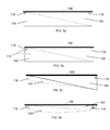
FIGS. 10 a-10 d depict some exemplary embodiments of the adjustable pad 100. The support members 104 can be coupled with the sheet 102, such that the support members 104 can provide at least partial support to the sheet 102. In some embodiments a single support member 104 can be coupled with the sheet 102. In other embodiments, a plurality of support members 104 can be coupled with the sheet 102. In some embodiments, the support members 104 can be formed and/or adjusted to at least partially conform to a surface 126. The surface 126 can be any type of surface. In various embodiments, the surface 126 can be slanted, rough, hard, bumpy, variable, level, and/or have any other properties or configuration. In some embodiments, the surface 126 can be part of an existing structure. By way of a non-limiting example, the surface 126 can be a slanted portion of a vehicle's seat. In other embodiments, the surface 126 can be a natural formation. By way of a non-limiting example, the surface 126 can be a portion of the ground outdoors.
In some embodiments, one or more of the support members 104 can be formed and/or adjusted to change the gradient of the sheet 102, regardless of the slope or configuration of the surface 126. In some embodiments, the sheet 102 can be positioned in a substantially level configuration, as shown in FIG. 10 a. In other embodiments, the support members 104 can be formed and/or adjusted such that the sheet 102 can have a concave depression, as shown in FIG. 10 b. In some embodiments, as shown in FIG. 10 c, the support members can be coupled with a portion of the sheet 102, such that the remainder of the sheet 102 is unsupported. In some embodiments, the adjustable pad 100 can be permanently or temporarily stored within an exterior cover 126, as shown in FIG. 10 d.
FIGS. 11 a and 11 b depicts an embodiment of the adjustable pad 100 in use. The adjustable pad 100 can be placed on a surface 126. The support members 104 can be formed and/or adjusted such that the sheet 102 is substantially level and/or has a concave depression regardless of the slope or other characteristics of the surface 126. In some embodiments, the user can then place a child 130 on the top of the sheet 102 in order to change the child 130's diaper, let the child 130 sleep and/or rest, clean the child 130, feed the child 130, or for any other desired reason. By way of a non-limiting example, the adjustable pad 100 can have a concave sheet 102 such that the potential for a child to roll is limited despite a flat surface 126, as shown in FIG. 11 a. By way of another non-limiting example, the adjustable pad 100 can have a concave sheet 102 such that the potential for a child to roll is limited despite a slanted surface 126, as shown in FIG. 11 b. In other embodiments, the adjustable pad 100 can be used in non-childcare situations, such that a user can sleep on the sheet 102 on uneven and/or uncomfortable surfaces 126, for example while camping; rest items on the sheet 102 regardless of the characteristics of the surface 126; use the adjustable pad 100 as a mattress pad; or use the adjustable pad 100 for any other desired purpose.
FIGS. 12 a and 12 b depict examples of an embodiment of the adjustable pad 100 in use. In the example shown in FIG. 12 a, the surface 126 is the seat of a chair that is angled forward, such that the sitting surface slants downward toward the front of the chair. In order to position the sheet 102 in a substantially level configuration despite the slope of the chair seat, the support member 104 a can be moved to the contracted position while the support member 104 b can be moved to the expanded position. The adjustable pad 100 can be used with a child or other user in the manner described with respect to FIGS. 11 a-11 b. Similarly, in the example shown in FIG. 12 b the surface 126 is the seat of a chair that is angled backward, such that the sitting surface slants upward toward the front of the chair. In order to position the sheet 102 in a substantially level configuration despite the slope of the chair seat, the support member 104 a can be moved to the expanded position while the support member 104 b can be moved to the contracted position. The adjustable pad 100 can be used with a child or other user in the manner described with respect to FIGS. 11 a-11 b.
FIGS. 13 a and 13 b depict examples of an embodiment of the adjustable pad 100 in use. In this non-limiting exemplary embodiment, the support members 104 can be coupled with a portion of the sheet 102, such that the remainder of the sheet 102 is unsupported, as shown in FIG. 10 c. In the example shown in FIG. 13 a, the surface 126 is the seat of a chair that is angled backward, such that the sitting surface slants upward toward the front of the chair. In order to position the sheet 102 in a partially level configuration despite the slope of the chair seat, the support member 104 a can be moved to the expanded position while the support member 104 b can be moved to the contracted position. The remainder of the sheet 102 can be positioned to cover other surfaces of the chair, such as the back of the chair and/or the front of the chair. The adjustable pad 100 can be used with a child or other user in the manner described with respect to FIGS. 11 a-11 b. Similarly, in the example shown in FIG. 13 b, the surface 126 is the seat of a chair that is angled forward, such that the sitting surface slants downward toward the front of the chair. In order to position the sheet 102 in a partially level configuration despite the slope of the chair seat, the support member 104 a can be moved to the contracted position while the support member 104 b can be moved to the expanded position. The remainder of the sheet 102 can be positioned to cover other surfaces of the chair, such as the back of the chair and/or the front of the chair. The adjustable pad 100 can be used with a child or other user in the manner described with respect to FIGS. 11 a-11 b.
FIGS. 14 a-14 c depict an example of an embodiment of the adjustable pad 100 in use. In this non-limiting exemplary embodiment, the support members 104 can be hingeably coupled, as shown in FIG. 9 d. The adjustable pad 100 can be used on a flat surface 126 in the configuration shown in FIG. 14 a. If the surface 126 is slanted, the support member 104 b can be rotated such that it is below the support member 104 a, as shown in FIG. 14 b. The adjustable pad 100 can then be placed on the slanted surface 126 as shown in FIG. 14 c, such that the top of the support member 104 a is substantially level due to the presence of the support member 104 b underneath a portion of it. The adjustable pad 100 can be used with a child or other user in the manner described with respect to FIGS. 11 a-11 b.
FIGS. 15 a-15 d depict an embodiment of the adjustable pad 100 in use. In this non-limiting exemplary embodiment, each of the support members 104 can be hingeably coupled to an intermediate extension 132 with hinge mechanisms 124, and the intermediate extensions 132 can be hingeably coupled to the sheet 102 with hinge mechanisms 124. As shown in FIG. 15 a, the support members 104 can be positioned against one another such that together they support at least a portion of the sheet 102. If desired, the adjustable pad 100 can be placed on a surface 126 in this configuration in order to use the adjustable pad 100 with a child or other user in the manner described with respect to FIGS. 11 a-11 b. Alternatively, the support members 104 and the intermediate extensions 132 can be rotated about the hinge mechanisms 124 as shown in FIG. 15 b, such that the support members 104 rest against the underside of the sheet 102 at the sides of the sheet 102, as shown in FIG. 15 c. The support members 104 can then be placed on a surface 126 in order to use the adjustable pad 100 with a child or other user in the manner described with respect to FIGS. 11 a-11 b. Additionally, the adjustable pad 100 can be inverted and the sheet 102 can be placed against the surface 126, such that the support members 104 can be above the sheet 102, as shown in FIG. 15 d. In this configuration, the child 130 or other user can rest on top of the sheet 102 between the support members 104, such that the child 130 or other user cannot easily roll past the support members 104. In some embodiments, the support members 104 can further comprise contraction mechanisms 122.
FIGS. 16 a-16 d depict an embodiment of the adjustable pad 100 in use. In this non-limiting exemplary embodiment, one of the support members 104 can be hingeably coupled to an intermediate extension 132 with hinge mechanisms 124. The intermediate extension 132 can be in turn be hingeably coupled to the sheet 102 with hinge mechanisms 124. The other support member 104 can be directly hingeably coupled with the sheet 102 with hinge mechanisms 124. As shown in FIG. 16 a, the support members 104 can be positioned against one another such that together they support at least a portion of the sheet 102. If desired, the adjustable pad 100 can be placed on a surface 126 in this configuration in order to use the adjustable pad 100 with a child or other user in the manner described with respect to FIGS. 11 a-11 b. Alternatively, the support members 104 and the intermediate extension 132 can be rotated about the hinge mechanisms 124 as shown in FIG. 16 b, such that the support members 104 rest against the underside of the sheet 102 at the sides of the sheet 102, as shown in FIG. 16 c. The support members 104 can then be placed on a surface 126 in order to use the adjustable pad 100 with a child or other user in the manner described with respect to FIGS. 11 a-11 b. Additionally, the adjustable pad 100 can be inverted and the sheet 102 can be placed against the surface 126, such that the support members 104 can be above the sheet 102, as shown in FIG. 16 d. In this configuration, the child 130 or other user can rest on top of the sheet 102 between the support members 104, such that the child 130 or other user cannot easily roll past the support members 104. In some embodiments, the support members 104 can further comprise contraction mechanisms 122.
FIGS. 17 a-17 d depict an embodiment of the adjustable pad 100 in use. In this non-limiting exemplary embodiment, the support members 104 can have a wedge shape with the cross section of a right triangle. In this exemplary embodiment, the surface of support member 104 a corresponding to the hypotenuse side of the right triangle can be directly coupled with the sheet 102, and the surface of support member 104 b corresponding to one of the non-hypotenuse legs of the right triangle can be directly coupled with the sheet 102. As shown in FIG. 17 a, the sheet 120 can be folded such that the support members 104 can be folded within the sheet 120. If desired, the adjustable pad 100 can be placed on a surface 126 in this configuration in order to use the adjustable pad 100 with a child or other user in the manner described with respect to FIGS. 11 a-11 b. Alternatively, as shown in FIGS. 17 b-c, the support members 104 can be rotated away from one another, such that the support members 104 can be on opposing ends of the sheet 102. In some embodiments, the sheet 102 can be flexible enough to allow the support members 104 to be rotated. In other embodiments, the sheet can comprise hinge mechanisms 124 that allow sections of the sheet 102 to be rotated. In still other embodiments, the sheet can comprise fold portions 108. When the adjustable pad 100 has been unfolded, it can be placed on a surface 126 in order to use the adjustable pad 100 with a child or other user in the manner described with respect to FIGS. 11 a-11 b. Additionally, the adjustable pad 100 can be inverted and the sheet 102 can be placed against the surface 126, such that the support members 104 can be above the sheet 102, as shown in FIG. 17 d. In this configuration, the child 130 or other user can rest on top of the sheet 102 between the support members 102, such that the child 130 or other user cannot easily roll past the support members 104. In some embodiments, the support members 104 can further comprise contraction mechanisms 122.
FIGS. 18 a-18 d depict an embodiment of the adjustable pad 100 in use. In this non-limiting exemplary embodiment, the support members 104 can have a wedge shape with the cross section of a right triangle. In this exemplary embodiments, the surface of support member 104 a corresponding to the hypotenuse side of the right triangle can be directly coupled with the sheet 102, and the surface of support member 104 b corresponding to one of the non-hypotenuse legs of the right triangle can be directly coupled with the sheet 102. As shown in FIG. 18 a, the sheet 120 can be folded such that the support members 104 can be folded within the sheet 120. If desired, the adjustable pad 100 can be placed on a surface 126 in this configuration in order to use the adjustable pad 100 with a child or other user in the manner described with respect to FIGS. 11 a-11 b. Alternatively, as shown in FIGS. 18 b-c, the support members 104 can be rotated away from one another, such that the support members 104 can be on opposing ends of the sheet 102. In some embodiments, the sheet 102 can be flexible enough to allow the support members 104 to be rotated. In other embodiments, the sheet can comprise hinge mechanisms 124 that allow sections of the sheet 102 to be rotated. In still other embodiments, the sheet can comprise fold portions 108. When the adjustable pad 100 has been unfolded, it can be placed on a surface 126 in order to use the adjustable pad 100 with a child or other user in the manner described with respect to FIGS. 11 a-11 b. Additionally, the adjustable pad 100 can be inverted and the sheet 102 can be placed against the surface 126, such that the support members 104 can be above the sheet 102, as shown in FIG. 18 d. In this configuration, the child 130 or other user can rest on top of the sheet 102 between the support members 102, such that the child 130 or other user cannot easily roll past the support members 104. In some embodiments, the support members 104 can further comprise contraction mechanisms 122.
Although the invention has been described in conjunction with specific embodiments thereof, it is evident that many alternatives, modifications and variations will be apparent to those skilled in the art. Accordingly, the invention as described and hereinafter claimed is intended to embrace all such alternatives, modifications and variations that fall within the spirit and broad scope of the appended claims.

Claims (8)

What is claimed is:
1. An adjustable pad, comprising:
a sheet;
a second inflatable wedge-shaped support member;
wherein said first inflatable wedge-shaped support member has a first surface extending along a first side of said first inflatable wedge-shaped support member that is entirely fixed to said sheet,
wherein said first inflatable wedge-shaped support member and said second inflatable wedge-shaped support member each have a second surface extending along a second side of said first inflatable wedge-shaped support member and said second inflatable wedge-shaped support member, said second surface being longer than said first surface,
wherein the second surface of said first inflatable wedge-shaped support member is entirely and directly fixed to the second surface of said second inflatable wedge-shaped support member, and
wherein said first inflatable wedge-shaped support member and said second inflatable wedge-shaped support member are configured to be at least partially inflated and/or deflated to select the gradient of said sheet relative to the configuration of a surface upon which said adjustable pad is placed.
2. The adjustable pad of claim 1, wherein said first inflatable wedge-shaped support member and said second inflatable wedge-shaped support member are configured to be at least partially inflated and/or deflated to adjust the gradient of said sheet to be substantially level regardless of the slope of said surface.
3. The adjustable pad of claim 1, wherein said first inflatable wedge-shaped support member and said second inflatable wedge-shaped support member are configured to be at least partially inflated and/or deflated to adjust the sheet to have a concave portion regardless of the slope of said surface.
4. The adjustable pad of claim 1, wherein at least one of said first inflatable wedge-shaped support member and said second inflatable wedge-shaped support member comprise a casing defining an interior chamber.
5. The adjustable pad of claim 1, wherein at least one of said first inflatable wedge-shaped support member and said second inflatable wedge-shaped support member are self-inflating.
6. The adjustable pad of claim 4, wherein said casing has one or more apertures configured to allow air to enter and/or exit the interior chamber.
7. The adjustable pad of claim 6, wherein at least one of said first inflatable wedge-shaped support member and said second inflatable wedge-shaped support member comprise a pump configured to pump said air into and/or out of said interior chamber through said apertures.
8. The adjustable pad of claim 1, wherein said adjustable pad is configured to be adjusted between an expanded position, a contracted position, and an intermediate position by adjusting the inflation levels of said first inflatable support member and/or said second inflatable wedge-shaped support member.
US13/540,487 2011-06-30 2012-07-02 Adjustable pad Active US9241581B2 (en)

Priority Applications (1)

Application Number Priority Date Filing Date Title
US13/540,487 US9241581B2 (en) 2011-06-30 2012-07-02 Adjustable pad

Applications Claiming Priority (2)

Application Number Priority Date Filing Date Title
US201161503611P 2011-06-30 2011-06-30
US13/540,487 US9241581B2 (en) 2011-06-30 2012-07-02 Adjustable pad

Publications (2)

Publication Number Publication Date
US20130025063A1 US20130025063A1 (en) 2013-01-31
US9241581B2 true US9241581B2 (en) 2016-01-26

Family

ID=47424592

Family Applications (1)

Application Number Title Priority Date Filing Date
US13/540,487 Active US9241581B2 (en) 2011-06-30 2012-07-02 Adjustable pad

Country Status (2)

Country Link
US (1) US9241581B2 (en)
WO (1) WO2013003862A1 (en)

Cited By (8)

* Cited by examiner, † Cited by third party
Publication number Priority date Publication date Assignee Title
US20200113342A1 (en) * 2018-10-11 2020-04-16 Bradley Craig Stone Air mattress systems with adjustable inclination
US10702048B1 (en) 2019-02-28 2020-07-07 Rockabye Backpack Inc. Backpack with integral changing pad
US20210106142A1 (en) * 2019-10-11 2021-04-15 Sean Kelly Adjustable, lower back restoration device
US11109799B2 (en) * 2017-10-24 2021-09-07 Hill-Rom Services, Inc. Modular turn assist apparatus and method therefor
US11330915B2 (en) 2015-03-30 2022-05-17 Kids2, Inc. Depth-adjustable bassinet
USD1024617S1 (en) * 2023-07-07 2024-04-30 Ningbo Platform Inc. Pillow
US12042453B2 (en) 2019-02-26 2024-07-23 Hill-Rom Services, Inc. Patient positioning apparatus and mattress
US12070130B1 (en) 2024-03-19 2024-08-27 Youngblood Ip Holdings, Llc Bedding components including fluid absorbing gel beads

Families Citing this family (3)

* Cited by examiner, † Cited by third party
Publication number Priority date Publication date Assignee Title
DK3170429T3 (en) * 2015-11-20 2021-01-11 Frank Wiegand PUZZLE MATTRESS, PUZZLE DEVICE WITH SUCH AND USE THEREOF
DE102018212729A1 (en) * 2018-07-31 2020-02-06 Robert Bosch Gmbh Method for producing a three-dimensional threshold compensation element of a battery module and battery module with one
US20220279939A1 (en) * 2021-03-05 2022-09-08 Oregon Health & Science University Infant feeding positioning cushion

Citations (79)

* Cited by examiner, † Cited by third party
Publication number Priority date Publication date Assignee Title
US1726939A (en) * 1927-03-14 1929-09-03 New York Rubber Corp Pneumatic cushion
US3568225A (en) * 1968-11-29 1971-03-09 Universal Oil Prod Co Vehicle cushion having positionable bolster cushions
US3680917A (en) 1970-05-18 1972-08-01 Carl Robert Harris Inflatable back and head floor rest
US3763509A (en) 1972-11-17 1973-10-09 T Mittendorf Adjustable pillow apparatus
US3775785A (en) * 1972-12-26 1973-12-04 T Mittendorf Adjustable pillow apparatus
US3811140A (en) * 1972-09-18 1974-05-21 D Burpo Body support device
US4171549A (en) 1977-09-07 1979-10-23 Gray Harold A Cushion ensemble and method of arranging cushions to provide the same
US4607403A (en) 1984-09-14 1986-08-26 Alivizatos Margaret A Infant support pads
US4667356A (en) 1986-02-03 1987-05-26 Marsha Holmquist Adjustable infant bed and seat
US4685163A (en) * 1985-04-16 1987-08-11 Quillen Jeffrey B Recliner for medical convalescence
US4697290A (en) 1984-03-07 1987-10-06 Regionala Stiftelsen I Varmland Med Firma Erress Device comprising a mattress support
US4934002A (en) 1989-06-20 1990-06-19 Kabushiki Kaisha Nihon M.D.M. Tiltable mat assembly
US4962553A (en) 1989-04-19 1990-10-16 Marquis Charles E Inflatable mattress structure
US5002014A (en) 1990-03-19 1991-03-26 Steve Albin Animal mattress
US5079786A (en) * 1991-07-12 1992-01-14 Rojas Adrian Q Cushion with magnetic spheres in a viscous fluid
US5088139A (en) * 1991-08-02 1992-02-18 Pockets Of Learning Portable infant's play mat with integral carrying case
US5154649A (en) 1991-09-10 1992-10-13 Vicki Pender Inflatable nursing pillow
US5182828A (en) 1991-03-06 1993-02-02 Maurice Adam Roll preventing structures
US5303435A (en) 1993-01-27 1994-04-19 Haar James M Self-inflating camping mattress having a tapered profile
US5345630A (en) 1993-07-15 1994-09-13 Jack Healy Quick inflatable air mattress
US5392477A (en) * 1993-12-22 1995-02-28 Wolter; Jon Sleeping bag with inflatable wedge portion
US5632055A (en) 1992-08-04 1997-05-27 Graf; Josef Inflatable object, in particular an air mattress, comprising a section serving as a pump and a section to be inflated by the pump
USD389359S (en) * 1996-10-31 1998-01-20 The First Years Inc. Infant support cushion
US5711041A (en) 1996-03-27 1998-01-27 Csa, Inc. Inflatable air mattress with internal pump
US5852838A (en) 1996-09-24 1998-12-29 Johnson; Christopher W. Cushion and method for providing a substantially flat diaper-changing surface for vehicle seats
US5899529A (en) 1996-11-21 1999-05-04 Chaucer; Jane E. Childs safety seat bolster
US5924661A (en) 1997-07-03 1999-07-20 Chernack; Milton Device for levelling and stabilizing an article of furniture
US5970550A (en) 1996-04-29 1999-10-26 Gazes; Jimmy Multiple compartment inflatable mattress
US6125487A (en) * 1995-02-10 2000-10-03 Ive; Ronald A. Infant support cushion
US6170908B1 (en) * 1999-09-28 2001-01-09 Richard Owen Jewell Convertible foot stool
USD446676S1 (en) 2000-09-18 2001-08-21 William F. Mayes Folding wedge pillow
US6298511B1 (en) 2000-05-04 2001-10-09 Deborah D. Collymore Articulated air mattress
US20010040402A1 (en) * 2000-05-12 2001-11-15 Odderson Ib R. Adjustable split seat
US6381787B1 (en) * 2000-02-09 2002-05-07 Small Beginnings, Inc. Infant positioning device
US20030037379A1 (en) * 2001-08-21 2003-02-27 Gibson Robert G Inflatable cushion with built-in carrying case
US6561582B1 (en) 1999-11-13 2003-05-13 William David Steadman Support apparatus
US6601252B1 (en) * 2002-03-05 2003-08-05 Jamie S. Leach Double pillowcase with attached anchor pad
US6665893B2 (en) 2001-04-06 2003-12-23 L & P Property Management Company Sofa sleeper with integral air mattress and valve
US6671900B2 (en) * 2000-03-08 2004-01-06 Waldon Davis Bed leveler/adjuster
US20040025254A1 (en) 2002-08-08 2004-02-12 Mccarthy Kevin D. Self-inflating changing pad
US6691348B2 (en) 2001-02-26 2004-02-17 Stephen B. Plummer Bed with adjustable positions
US6754920B2 (en) * 2000-01-07 2004-06-29 T. L. Clark, Incorporated Infection control mat
USD504270S1 (en) * 2002-09-02 2005-04-26 Jacpaq Limited Head support
US20050210593A1 (en) * 2003-04-25 2005-09-29 Stackman Lisa F Rigid foldable portable diaper changing pad
US6971127B2 (en) * 2000-12-22 2005-12-06 Hill-Rom Services, Inc. Infant rocking apparatus
US20060016013A1 (en) * 2004-07-23 2006-01-26 John Lord Infant changing station and method of use therewith
US7007330B2 (en) 2000-12-08 2006-03-07 Autonurse, Inc. Portable patient turning and lifting device
US7007328B1 (en) 2004-11-05 2006-03-07 Terry Bailey System and apparatus for upper body support of a recumbent person
US20060053552A1 (en) * 2004-03-01 2006-03-16 The Coleman Company, Inc. Sleeping bag with cinching mechanism
US20060080779A1 (en) * 2004-10-18 2006-04-20 Munro Susan E Infant support device
US7059000B2 (en) * 2002-04-10 2006-06-13 Verbovszky Esther A L Portable infant cushion
USD523679S1 (en) * 2005-01-10 2006-06-27 Worth While Pillows, Inc. Adjustable travel pillow
US7127762B1 (en) * 2005-05-12 2006-10-31 Ideal Time Consultants Limited Inflatable product with stowable pump
US20070122066A1 (en) * 2005-05-23 2007-05-31 Landay Lisa A Diaper Changing Accessory Organizer
US7231681B2 (en) 2003-01-24 2007-06-19 Victor M. Kasatshko Multiple position air mattress system
US7305728B2 (en) * 2004-10-20 2007-12-11 Schlieps Mark A Plumbers support pillow
US20080016623A1 (en) 2006-07-20 2008-01-24 Gold Bug, Inc. Infant diaper changing system
US7346951B1 (en) * 2006-11-09 2008-03-25 Heaton Steven C Bedsore reduction system for beds
US20080172795A1 (en) * 2007-01-19 2008-07-24 Mariann Straub Infant wedge sleep positioner
US20080216245A1 (en) * 2007-03-05 2008-09-11 Eric Liners Universal Portable Seat Cushion
US7497513B2 (en) * 2004-01-26 2009-03-03 Tae-Sook Kim Buffer cushion for automobiles
US7509699B1 (en) 2007-02-21 2009-03-31 Eugene Lee Tresenfeld Leveling camping pad
US20090126117A1 (en) 2007-11-15 2009-05-21 Julian Eric Lazarus Conforming multi-position pillow with pressure dispersal system
US20090151080A1 (en) * 2007-01-24 2009-06-18 Summer Infant (Usa), Inc. Sleep aid with position indicator along with method incorporating same
US7607185B1 (en) 2008-07-14 2009-10-27 Kelli L. Minson Inflatable incline mattress
TW201012422A (en) 2008-09-23 2010-04-01 Her Chian Acrylic Co Ltd Pillow
CN201499931U (en) 2009-09-04 2010-06-09 孙同春 Adjustable pillow
US7735170B1 (en) 2005-05-16 2010-06-15 Parental Solutions, Inc. Diaper changing pad
US7757320B2 (en) * 2006-05-16 2010-07-20 Summer Infant, Inc. Infant changing pad
US7761944B2 (en) * 2007-12-20 2010-07-27 Charlotte Skophammer Baby changing duffel
TW201036579A (en) 2009-04-03 2010-10-16 hong-jian Zhou Height-adjustable pillow
US20110000023A1 (en) * 2009-07-06 2011-01-06 Michael Sean Kennedy Diaper changing apparatus
KR20110002819A (en) 2010-11-17 2011-01-10 황종범 Equipped with height-adjustable pillow core
CN201759231U (en) 2010-08-26 2011-03-16 李科 Cervical rehabilitation pillow with manual adjustment
US20110119832A1 (en) * 2009-11-23 2011-05-26 Chien-Hsiung Hung Part-detachable, foldable, and portable safety infant bed
US8181295B1 (en) * 2009-12-16 2012-05-22 Mallinger Michael R Adjustable air mattress device
US8276227B2 (en) * 2009-12-23 2012-10-02 Pileggi Vincent J Multi-adjustable pillow
US8419128B1 (en) * 2007-10-03 2013-04-16 Jamie S. Leach Car seat insert with elastic under-body panel
US8671480B1 (en) * 2007-09-04 2014-03-18 Jamie S. Leach Multi-purpose pillow system

Patent Citations (79)

* Cited by examiner, † Cited by third party
Publication number Priority date Publication date Assignee Title
US1726939A (en) * 1927-03-14 1929-09-03 New York Rubber Corp Pneumatic cushion
US3568225A (en) * 1968-11-29 1971-03-09 Universal Oil Prod Co Vehicle cushion having positionable bolster cushions
US3680917A (en) 1970-05-18 1972-08-01 Carl Robert Harris Inflatable back and head floor rest
US3811140A (en) * 1972-09-18 1974-05-21 D Burpo Body support device
US3763509A (en) 1972-11-17 1973-10-09 T Mittendorf Adjustable pillow apparatus
US3775785A (en) * 1972-12-26 1973-12-04 T Mittendorf Adjustable pillow apparatus
US4171549A (en) 1977-09-07 1979-10-23 Gray Harold A Cushion ensemble and method of arranging cushions to provide the same
US4697290A (en) 1984-03-07 1987-10-06 Regionala Stiftelsen I Varmland Med Firma Erress Device comprising a mattress support
US4607403A (en) 1984-09-14 1986-08-26 Alivizatos Margaret A Infant support pads
US4685163A (en) * 1985-04-16 1987-08-11 Quillen Jeffrey B Recliner for medical convalescence
US4667356A (en) 1986-02-03 1987-05-26 Marsha Holmquist Adjustable infant bed and seat
US4962553A (en) 1989-04-19 1990-10-16 Marquis Charles E Inflatable mattress structure
US4934002A (en) 1989-06-20 1990-06-19 Kabushiki Kaisha Nihon M.D.M. Tiltable mat assembly
US5002014A (en) 1990-03-19 1991-03-26 Steve Albin Animal mattress
US5182828A (en) 1991-03-06 1993-02-02 Maurice Adam Roll preventing structures
US5079786A (en) * 1991-07-12 1992-01-14 Rojas Adrian Q Cushion with magnetic spheres in a viscous fluid
US5088139A (en) * 1991-08-02 1992-02-18 Pockets Of Learning Portable infant's play mat with integral carrying case
US5154649A (en) 1991-09-10 1992-10-13 Vicki Pender Inflatable nursing pillow
US5632055A (en) 1992-08-04 1997-05-27 Graf; Josef Inflatable object, in particular an air mattress, comprising a section serving as a pump and a section to be inflated by the pump
US5303435A (en) 1993-01-27 1994-04-19 Haar James M Self-inflating camping mattress having a tapered profile
US5345630A (en) 1993-07-15 1994-09-13 Jack Healy Quick inflatable air mattress
US5392477A (en) * 1993-12-22 1995-02-28 Wolter; Jon Sleeping bag with inflatable wedge portion
US6125487A (en) * 1995-02-10 2000-10-03 Ive; Ronald A. Infant support cushion
US5711041A (en) 1996-03-27 1998-01-27 Csa, Inc. Inflatable air mattress with internal pump
US5970550A (en) 1996-04-29 1999-10-26 Gazes; Jimmy Multiple compartment inflatable mattress
US5852838A (en) 1996-09-24 1998-12-29 Johnson; Christopher W. Cushion and method for providing a substantially flat diaper-changing surface for vehicle seats
USD389359S (en) * 1996-10-31 1998-01-20 The First Years Inc. Infant support cushion
US5899529A (en) 1996-11-21 1999-05-04 Chaucer; Jane E. Childs safety seat bolster
US5924661A (en) 1997-07-03 1999-07-20 Chernack; Milton Device for levelling and stabilizing an article of furniture
US6170908B1 (en) * 1999-09-28 2001-01-09 Richard Owen Jewell Convertible foot stool
US6561582B1 (en) 1999-11-13 2003-05-13 William David Steadman Support apparatus
US6754920B2 (en) * 2000-01-07 2004-06-29 T. L. Clark, Incorporated Infection control mat
US6381787B1 (en) * 2000-02-09 2002-05-07 Small Beginnings, Inc. Infant positioning device
US6671900B2 (en) * 2000-03-08 2004-01-06 Waldon Davis Bed leveler/adjuster
US6298511B1 (en) 2000-05-04 2001-10-09 Deborah D. Collymore Articulated air mattress
US20010040402A1 (en) * 2000-05-12 2001-11-15 Odderson Ib R. Adjustable split seat
USD446676S1 (en) 2000-09-18 2001-08-21 William F. Mayes Folding wedge pillow
US7007330B2 (en) 2000-12-08 2006-03-07 Autonurse, Inc. Portable patient turning and lifting device
US6971127B2 (en) * 2000-12-22 2005-12-06 Hill-Rom Services, Inc. Infant rocking apparatus
US6691348B2 (en) 2001-02-26 2004-02-17 Stephen B. Plummer Bed with adjustable positions
US6665893B2 (en) 2001-04-06 2003-12-23 L & P Property Management Company Sofa sleeper with integral air mattress and valve
US20030037379A1 (en) * 2001-08-21 2003-02-27 Gibson Robert G Inflatable cushion with built-in carrying case
US6601252B1 (en) * 2002-03-05 2003-08-05 Jamie S. Leach Double pillowcase with attached anchor pad
US7059000B2 (en) * 2002-04-10 2006-06-13 Verbovszky Esther A L Portable infant cushion
US20040025254A1 (en) 2002-08-08 2004-02-12 Mccarthy Kevin D. Self-inflating changing pad
USD504270S1 (en) * 2002-09-02 2005-04-26 Jacpaq Limited Head support
US7231681B2 (en) 2003-01-24 2007-06-19 Victor M. Kasatshko Multiple position air mattress system
US20050210593A1 (en) * 2003-04-25 2005-09-29 Stackman Lisa F Rigid foldable portable diaper changing pad
US7497513B2 (en) * 2004-01-26 2009-03-03 Tae-Sook Kim Buffer cushion for automobiles
US20060053552A1 (en) * 2004-03-01 2006-03-16 The Coleman Company, Inc. Sleeping bag with cinching mechanism
US20060016013A1 (en) * 2004-07-23 2006-01-26 John Lord Infant changing station and method of use therewith
US20060080779A1 (en) * 2004-10-18 2006-04-20 Munro Susan E Infant support device
US7305728B2 (en) * 2004-10-20 2007-12-11 Schlieps Mark A Plumbers support pillow
US7007328B1 (en) 2004-11-05 2006-03-07 Terry Bailey System and apparatus for upper body support of a recumbent person
USD523679S1 (en) * 2005-01-10 2006-06-27 Worth While Pillows, Inc. Adjustable travel pillow
US7127762B1 (en) * 2005-05-12 2006-10-31 Ideal Time Consultants Limited Inflatable product with stowable pump
US7735170B1 (en) 2005-05-16 2010-06-15 Parental Solutions, Inc. Diaper changing pad
US20070122066A1 (en) * 2005-05-23 2007-05-31 Landay Lisa A Diaper Changing Accessory Organizer
US7757320B2 (en) * 2006-05-16 2010-07-20 Summer Infant, Inc. Infant changing pad
US20080016623A1 (en) 2006-07-20 2008-01-24 Gold Bug, Inc. Infant diaper changing system
US7346951B1 (en) * 2006-11-09 2008-03-25 Heaton Steven C Bedsore reduction system for beds
US20080172795A1 (en) * 2007-01-19 2008-07-24 Mariann Straub Infant wedge sleep positioner
US20090151080A1 (en) * 2007-01-24 2009-06-18 Summer Infant (Usa), Inc. Sleep aid with position indicator along with method incorporating same
US7509699B1 (en) 2007-02-21 2009-03-31 Eugene Lee Tresenfeld Leveling camping pad
US20080216245A1 (en) * 2007-03-05 2008-09-11 Eric Liners Universal Portable Seat Cushion
US8671480B1 (en) * 2007-09-04 2014-03-18 Jamie S. Leach Multi-purpose pillow system
US8419128B1 (en) * 2007-10-03 2013-04-16 Jamie S. Leach Car seat insert with elastic under-body panel
US20090126117A1 (en) 2007-11-15 2009-05-21 Julian Eric Lazarus Conforming multi-position pillow with pressure dispersal system
US7761944B2 (en) * 2007-12-20 2010-07-27 Charlotte Skophammer Baby changing duffel
US7607185B1 (en) 2008-07-14 2009-10-27 Kelli L. Minson Inflatable incline mattress
TW201012422A (en) 2008-09-23 2010-04-01 Her Chian Acrylic Co Ltd Pillow
TW201036579A (en) 2009-04-03 2010-10-16 hong-jian Zhou Height-adjustable pillow
US20110000023A1 (en) * 2009-07-06 2011-01-06 Michael Sean Kennedy Diaper changing apparatus
CN201499931U (en) 2009-09-04 2010-06-09 孙同春 Adjustable pillow
US20110119832A1 (en) * 2009-11-23 2011-05-26 Chien-Hsiung Hung Part-detachable, foldable, and portable safety infant bed
US8181295B1 (en) * 2009-12-16 2012-05-22 Mallinger Michael R Adjustable air mattress device
US8276227B2 (en) * 2009-12-23 2012-10-02 Pileggi Vincent J Multi-adjustable pillow
CN201759231U (en) 2010-08-26 2011-03-16 李科 Cervical rehabilitation pillow with manual adjustment
KR20110002819A (en) 2010-11-17 2011-01-10 황종범 Equipped with height-adjustable pillow core

Non-Patent Citations (4)

* Cited by examiner, † Cited by third party
Title
Contour Living, "Backmax Body Wedge Cushion Sets", "Backmax Body Wedge Cushion Sets", Oct. 9, 2004, Publisher: Contour Living.
EXPED, "EXPED Synmat 7 Deluxe Air Pad With Built-In Hand Pump", "EXPED Synmat 7 Deluxe Air Pad With Built-In Hand Pump", 2006, Publisher: EXPED.
Thermarest, "Z Seat", "Z Seat", Apr. 29, 2009, Publisher: Thermarest.
Top of the Line, "Baby Seat Changer", "Baby Seat Changer", Nov. 11, 2006, Publisher: Top of the Line.

Cited By (12)

* Cited by examiner, † Cited by third party
Publication number Priority date Publication date Assignee Title
US11330915B2 (en) 2015-03-30 2022-05-17 Kids2, Inc. Depth-adjustable bassinet
US11930939B2 (en) 2015-03-30 2024-03-19 Kids2, Inc. Depth-adjustable bassinet
US11109799B2 (en) * 2017-10-24 2021-09-07 Hill-Rom Services, Inc. Modular turn assist apparatus and method therefor
US20210361229A1 (en) * 2017-10-24 2021-11-25 Hill-Rom Services, Inc. Modular turn assist apparatus and method therefor
US11872052B2 (en) * 2017-10-24 2024-01-16 Hill-Rom Services, Inc. Modular turn assist apparatus and method therefor
US20200113342A1 (en) * 2018-10-11 2020-04-16 Bradley Craig Stone Air mattress systems with adjustable inclination
US12042453B2 (en) 2019-02-26 2024-07-23 Hill-Rom Services, Inc. Patient positioning apparatus and mattress
US10702048B1 (en) 2019-02-28 2020-07-07 Rockabye Backpack Inc. Backpack with integral changing pad
US20210106142A1 (en) * 2019-10-11 2021-04-15 Sean Kelly Adjustable, lower back restoration device
US11576497B2 (en) * 2019-10-11 2023-02-14 Sean Kelly Adjustable, lower back restoration device
USD1024617S1 (en) * 2023-07-07 2024-04-30 Ningbo Platform Inc. Pillow
US12070130B1 (en) 2024-03-19 2024-08-27 Youngblood Ip Holdings, Llc Bedding components including fluid absorbing gel beads

Also Published As

Publication number Publication date
WO2013003862A1 (en) 2013-01-03
US20130025063A1 (en) 2013-01-31

Similar Documents

Publication Publication Date Title
US9241581B2 (en) Adjustable pad
US6692072B2 (en) Booster seat
US7246393B2 (en) Inflatable mattress
US9737153B2 (en) Configurable inflatable support devices
US6671910B2 (en) Inflatable bed
US9585494B2 (en) Infant lounger
US20140075670A1 (en) Portable and collapsible device and methods
US9668589B2 (en) Portable changing table
US20070056110A1 (en) Inflatable nursing pillow
US20050241064A1 (en) Convertible infant care apparatus
US20130187415A1 (en) Self-storable portable padding device
US9155402B1 (en) Folding playpen and dual sleeper
US10080444B2 (en) Folding playpen and dual sleeper
US20160316920A1 (en) Folding bed
US3464069A (en) Portable sunbathing cot
US7975337B2 (en) Fluidized bed
WO2008095295A1 (en) Tent with mattress
GB2519528A (en) Beds
US20060000020A1 (en) Airbed and cot combination
EP1552770A2 (en) Configurable inflatable device
US11191369B2 (en) Children's playpen mattress with rigid substrate and inflatable bladder
GB2522876A (en) An infant Mat
TWM561460U (en) Expandable and contractible mat
GB2563034A (en) Baby nest

Legal Events

Date Code Title Description
STCF Information on status: patent grant

Free format text: PATENTED CASE

AS Assignment

Owner name: O-GO ENTERPRISES LLC, OREGON

Free format text: ASSIGNMENT OF ASSIGNORS INTEREST;ASSIGNOR:O'NION, LAURIE, MS;REEL/FRAME:038780/0052

Effective date: 20160531

MAFP Maintenance fee payment

Free format text: PAYMENT OF MAINTENANCE FEE, 4TH YEAR, MICRO ENTITY (ORIGINAL EVENT CODE: M3551); ENTITY STATUS OF PATENT OWNER: MICROENTITY

Year of fee payment: 4

MAFP Maintenance fee payment

Free format text: PAYMENT OF MAINTENANCE FEE, 8TH YEAR, MICRO ENTITY (ORIGINAL EVENT CODE: M3552); ENTITY STATUS OF PATENT OWNER: MICROENTITY

Year of fee payment: 8