US9239237B2 - Optical alignment apparatus and methodology for a video based metrology tool - Google Patents
Optical alignment apparatus and methodology for a video based metrology tool Download PDFInfo
- Publication number
- US9239237B2 US9239237B2 US14/246,056 US201414246056A US9239237B2 US 9239237 B2 US9239237 B2 US 9239237B2 US 201414246056 A US201414246056 A US 201414246056A US 9239237 B2 US9239237 B2 US 9239237B2
- Authority
- US
- United States
- Prior art keywords
- target
- beamsplitter
- optical axis
- optical
- reflective
- Prior art date
- Legal status (The legal status is an assumption and is not a legal conclusion. Google has not performed a legal analysis and makes no representation as to the accuracy of the status listed.)
- Active, expires
Links
Images

Classifications
-
- G—PHYSICS
- G01—MEASURING; TESTING
- G01B—MEASURING LENGTH, THICKNESS OR SIMILAR LINEAR DIMENSIONS; MEASURING ANGLES; MEASURING AREAS; MEASURING IRREGULARITIES OF SURFACES OR CONTOURS
- G01B11/00—Measuring arrangements characterised by the use of optical techniques
- G01B11/26—Measuring arrangements characterised by the use of optical techniques for measuring angles or tapers; for testing the alignment of axes
- G01B11/27—Measuring arrangements characterised by the use of optical techniques for measuring angles or tapers; for testing the alignment of axes for testing the alignment of axes
- G01B11/272—Measuring arrangements characterised by the use of optical techniques for measuring angles or tapers; for testing the alignment of axes for testing the alignment of axes using photoelectric detection means
Definitions
- This invention generally relates to optical metrology apparatus and more particularly to apparatus and methodology for aligning an image forming optical system to a video metrology tool.
- Well-known metrology instruments contain a light source, test target, refractive or reflective collimator, and an image analyzer.
- the image analyzer is generally comprised of a relay lens and two-dimensional video sensor, such as a CCD camera for the visible spectrum or microbolometer for the long-wave infrared (LWIR) spectrum.
- the optical system to be tested (unit-under-test or UUT) forms an image of the illuminated test target at an infinite conjugate.
- the image analyzer captures this image for analysis to determine properties and qualities of the UUT.
- An example of such instruments is described in detail in U.S. Pat. No. 5,661,816 which issued on Aug. 26, 1997 in the name of Stephen D. Fantone, et al. with the title “IMAGE ANALYSIS SYSTEM.”
- the present invention comprises apparatus for quickly aligning a test optic with various components of the above-described optical metrology tool.
- a collimated target is presented to a reference surface located on a positioning system for holding and manipulating the test optic.
- Video images of the target and its reflection from the reference surface are displayed for analysis and visualization so that any tilt or other misalignment between the reference surface and the optical axis of the collimated beam can be removed to align the test optic.
- the video based system is used to quickly measure and display in real-time a variety of performance characteristics of optical components such as lenses.
- the metrology system is under the control of a computer which uses a windowing software program to provide the user with a graphical user interface by which the various components of the system and test lenses may be aligned and characterized.
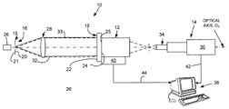
- FIG. 1 is a diagrammatic elevational view of an embodiment of an alignment apparatus in accordance with the invention.
- FIG. 2A is a diagrammatic representation of an image of a target formed directly by a video camera.
- FIG. 2B is a diagrammatic representation of the image of FIG. 2A and its image after having been reflected by a reference surface as an inverted and reverted image (white) of the target image (black).
- FIG. 1 diagrammatically shows an elevational view of the alignment apparatus 10 of the invention by which a unit under test 12 (UUT), such as a lens or the like, may be aligned prior to measurement in a video based metrology system 14 of the type described more fully in the aforementioned U.S. Pat. No. 5,661,816, which is incorporated herein in its entirety by reference.
- the present apparatus 10 and its associated alignment method require a specific type of alignment target 16 and a plane parallel beamsplitter 18 .
- the alignment target 16 should contain fine, transparent features, such as a crosshair, half circle, pinhole, or the like, placed against a reflective background.
- a target shown generally at 16 is preferably a flat opaque disk 15 with a transparent pattern in the form of a central pinhole or cross hair, or the like, that provides features allowing visualization of an axis or alignment center.
- the disk 15 has two sides, a front side 21 facing a light source 26 and reflective back side 20 facing a collimating lens 28 .
- the back side 20 of the disk 15 is usually coated with a material to increase the reflectivity of the disk 15 . If the disk 15 is uncoated, then the reflectivity and surface finish of the disk 15 determine the specularity of the reflection of the light that was directed back towards the target 16 by beamsplitter 18 and focused onto the back side 20 of the disk 15 by the collimating lens 28 , as more fully explained hereafter.
- the diffuseness and or reflectivity of the disk 15 substrate is insufficient, then it is advantageous to coat the back side 20 of the disk 15 with a coating that will enhance its reflectivity.
- a coating that will enhance its reflectivity.
- white paint such as white paint
- evaporated coatings such as Inconel®, chrome, aluminum, silver or gold.
- a diffuse coating such as white paint, ensures broad band reflection and truly diffuse reflection.
- the diffuseness of reflection is particularly important if the pupil of the beamsplitter 18 and lens under test 12 are decentered in the pupil of the collimator lens 28 .
- a retroreflective paint increases the amount of light that is directed directly back into the pupil of the beamsplitter 18 and lens under test 12 .
- the effectiveness of retro-reflective paints in increasing the amount of light directed back to its source is readily appreciated when comparing the improvement in road side signs coated with retroreflective paints with those with conventional paints.
- Targets are typically made of metal foil substrates using well-known techniques including laser cutting or chemical etching and other photolithographic techniques.
- Targets can be made on clear glass or other transmissive substrates coated with a substantially opaque coating such as aluminum, Inconel®, chrome, gold or other metal. It is important that this coating have an optical density of at least four to minimize any stray light passing through the system, as is usually required for accurate measurement of modulation transfer function.
- a crosshair with a pinhole in the center has been found successful and for operation in the infrared region of the spectrum, a quarter-open fishtail target (tungsten foil) has been used.
- tungsten foil tungsten foil
- one option is a fishtail or pinhole target on a infrared transmissive substrate.
- the target 16 is made with a substrate that has a smooth specular surface and if the pupil of the beamsplitter 18 and lens under test 12 are decentered relative to that of the collimator lens 28 , the light specularly reflected off the back side 20 of the target 16 may not be reflected back into the pupil of the beamsplitter 18 and the lens under test 12 .
- the front side 21 of the target 16 may be coated with a reflective material to minimize the absorption of light and the associated rise in temperature of the target 16 .
- the alignment target 16 can also serve as the primary test target for the metrology tool or is aligned to other test targets in the system through means of a target wheel or mechanical fixturing of the target mounts (not shown, but otherwise well-known).
- the plane parallel beamsplitter 18 generally requires parallelism of its two surfaces 22 and 24 within 1 arc minute.
- the beamsplitter 18 can be fabricated from optical glass containing a partially reflective coating on one side.
- the beamsplitter 18 can be fabricated from an infrared material containing a partially reflective coating or an uncoated piece of germanium.
- a light source 26 back-illuminates the alignment target 16 , such that bright features on a dark background are present.
- the alignment target 16 is located at the focal point of the collimator lens 28 .
- the plane parallel beamsplitter surface 24 is placed against a mechanical surface datum 25 on the front of UUT 12 .
- Collimated light 32 exiting the collimator lens 28 is first incident to the beamsplitter 18 . Some percentage of the light transmits through the beamsplitter 18 and some percentage reflects off the beamsplitter 18 back towards the target 16 , i.e., it is specularly reflected off the beamsplitter.
- the portion that transmits through the beamsplitter 18 is imaged by the UUT 12 and captured by the image analyzer 14 comprising a relay optic 34 and downstream camera 36 whose images are processed in a well-known manner via computer a computer 38 provided with programs containing suitable algorithms.
- This image of the alignment target 16 serves as our lens 28 and is reimaged onto the alignment target 16 .
- the alignment target 16 contains a reflective background (surface 20 )
- this image is reflected back through the collimator 18 and imaged by the UUT 12 .
- a second alignment target image is captured by the image analyzer 14 and is depicted as the white or empty semicircle shown in FIG. 2B along with the previously described black reference semicircle. Only when the UUT 12 is aligned to the optical axis of the collimator lens 28 will the two alignment target images be coincident. In FIG. 2B , the two images are vertically displaced with respect to the optical axis to depict a tilt between the optical axis of the UUT and that of the collimated beam.
- the two half circle images When no such tilt exists, the two half circle images would have their bases coincident to form a perfect circle centered on the optical axis of the collimator.
- the sensitivity of this alignment method is dependent upon the size of the features in the alignment target 16 , the focal lengths of the collimator and UUT, the magnification of the relay lens 34 in the image analyzer 14 , and the resolution of the camera in the image analyzer.
- a manually adjustable multi-degree of freedom precision stage or a computer controlled micromanipulator as designated generally at 40. If the later, control signals and processing information may be communicated to computer 38 with a suitable cable 44 or via wireless connections. Computer 38 may also be used to identify the UUT 12 properties, issue commands, acquire and process data, and perform routine housekeeping functions.
- the metrology system may also be under the control of computer 38 which preferably uses a windowing software program to provide the user with a graphical user interface by which the various components of the system and test lenses may be aligned and characterized.
- the method of the invention can also be used to align purely mechanical mounts.
- the relay lens 34 in the image analyzer 14 is replaced with a decollimating lens such that the alignment target 16 is directly imaged onto the video sensor of camera 36 without the UUT 12 in place.
- the plane parallel beamsplitter 18 is placed against the surface datum on the mount. The procedure for viewing and aligning the two alignment target images is the same.
- the plane parallel beamsplitter 18 is placed against a reference surface 25 on the lens that should be perpendicular to the optical axis of the lens.
- Light incident on the plane parallel beamsplitter 18 passes through it undeviated while light reflected off one or more surfaces of the plane parallel beamsplitter 18 is reflected back onto the target 16 .
- the image formed Due to the symmetry of the system, the image formed is inverted and is further displaced by an amount proportional to the tilt of the reference surface 25 relative to the direction of the optical axis of the collimated beam 32 .
- the optical axis of the collimated beam is at the geometric center+of the two images (See bottom left white half circle above black half circle in FIG. 2B .
- This procedure works very well with video based type systems such as that shown and described in the '816 patent. It is also particularly useful in the infra-red where it is usually very difficult to determine the direction of the collimated beam.
- the use of a target that has a reflective surround allows the user to have a direct view of the target and a view of the inverted return image from the beamsplitter 18 . This makes alignment of the UUT 12 to the optical axis of the collimator 28 very easy to perform.
- One useful beamsplitter for use in the visible had a reflection/transmission ratio of 70/30, and an uncoated germanium window that was used for the infrared beamsplitter had an effective 60/40 ratio from Fresnel reflections.
- the relative brightness of the direct viewed target to the reflected image is: T b /( R b ⁇ R t ⁇ T b ) Which is equal to 1/(R b ⁇ R t ) where T b is the single pass transmission of the beamsplitter, R b is the reflectance of the beamsplitter, and R t is the reflectance of the target surround in the target.
- the source 26 for illuminating target 16 may be any well-known source whose output encompasses the operating wavelengths of the UUT 12 under test.
Landscapes
- Physics & Mathematics (AREA)
- General Physics & Mathematics (AREA)
- Investigating Or Analysing Materials By Optical Means (AREA)
- Engineering & Computer Science (AREA)
- Health & Medical Sciences (AREA)
- Biomedical Technology (AREA)
- General Health & Medical Sciences (AREA)
- Multimedia (AREA)
- Signal Processing (AREA)
Abstract
Description
T b/(R b ×R t ×T b)
Which is equal to 1/(Rb ×R t)
where Tb is the single pass transmission of the beamsplitter, Rb is the reflectance of the beamsplitter, and Rt is the reflectance of the target surround in the target.
Claims (15)
T b/(R b ×R t ×T b)
Priority Applications (1)
| Application Number | Priority Date | Filing Date | Title |
|---|---|---|---|
| US14/246,056 US9239237B2 (en) | 2013-04-08 | 2014-04-05 | Optical alignment apparatus and methodology for a video based metrology tool |
Applications Claiming Priority (2)
| Application Number | Priority Date | Filing Date | Title |
|---|---|---|---|
| US201361809755P | 2013-04-08 | 2013-04-08 | |
| US14/246,056 US9239237B2 (en) | 2013-04-08 | 2014-04-05 | Optical alignment apparatus and methodology for a video based metrology tool |
Publications (2)
| Publication Number | Publication Date |
|---|---|
| US20140300751A1 US20140300751A1 (en) | 2014-10-09 |
| US9239237B2 true US9239237B2 (en) | 2016-01-19 |
Family
ID=51654158
Family Applications (1)
| Application Number | Title | Priority Date | Filing Date |
|---|---|---|---|
| US14/246,056 Active 2034-07-24 US9239237B2 (en) | 2013-04-08 | 2014-04-05 | Optical alignment apparatus and methodology for a video based metrology tool |
Country Status (1)
| Country | Link |
|---|---|
| US (1) | US9239237B2 (en) |
Families Citing this family (8)
| Publication number | Priority date | Publication date | Assignee | Title |
|---|---|---|---|---|
| US9689669B2 (en) * | 2015-04-14 | 2017-06-27 | Raytheon Company | Image plane sensor alignment system and method |
| CN106403990B (en) * | 2015-07-31 | 2019-07-12 | 北京航天计量测试技术研究所 | A kind of light axis consistency caliberating device |
| CN106705991B (en) * | 2015-08-07 | 2020-12-15 | 北京航天计量测试技术研究所 | A strapdown inertial group sighting prism installation error test equipment |
| US10436640B2 (en) | 2017-10-17 | 2019-10-08 | Raytheon Company | Alignment assembly and method for multi-spectral optical systems |
| US10337857B2 (en) | 2017-10-17 | 2019-07-02 | Raytheon Company | Multi-spectral boresight alignment methods and systems |
| CN109029302B (en) * | 2018-08-16 | 2023-09-26 | 珠海市运泰利自动化设备有限公司 | Camera centering accuracy verification machine and verification method thereof |
| CN110025285B (en) * | 2019-05-05 | 2023-10-20 | 厦门通测电子有限公司 | Automatic calibration device and calibration method for optometry lens box |
| KR102083759B1 (en) * | 2019-07-31 | 2020-03-02 | (주)이즈미디어 | Apparatus for inspecting alignment of optical device |
Citations (7)
| Publication number | Priority date | Publication date | Assignee | Title |
|---|---|---|---|---|
| US3766466A (en) * | 1971-11-26 | 1973-10-16 | Us Navy | Device for simultaneously q-switching several independent ruby lasers |
| US4180325A (en) * | 1977-07-05 | 1979-12-25 | Humphrey Instruments, Inc. | Lens meter with automated readout |
| US5066120A (en) * | 1989-06-05 | 1991-11-19 | Essilor International, Cie Generale D'optique | Optical device for phase detection testing optical system, especially ophthalmic lenses |
| US5576780A (en) * | 1992-05-26 | 1996-11-19 | Cain Research Pty. Ltd. | Method for evaluation of length of focus of the eye |
| US5661816A (en) * | 1991-10-22 | 1997-08-26 | Optikos Corporation | Image analysis system |
| US20120025714A1 (en) * | 2010-07-28 | 2012-02-02 | Downing Jr John P | High-stability light source system and method of manufacturing |
| US20130128333A1 (en) * | 2011-01-11 | 2013-05-23 | Ajjer Llc | Added feature electrooptical devices and automotive components |
-
2014
- 2014-04-05 US US14/246,056 patent/US9239237B2/en active Active
Patent Citations (7)
| Publication number | Priority date | Publication date | Assignee | Title |
|---|---|---|---|---|
| US3766466A (en) * | 1971-11-26 | 1973-10-16 | Us Navy | Device for simultaneously q-switching several independent ruby lasers |
| US4180325A (en) * | 1977-07-05 | 1979-12-25 | Humphrey Instruments, Inc. | Lens meter with automated readout |
| US5066120A (en) * | 1989-06-05 | 1991-11-19 | Essilor International, Cie Generale D'optique | Optical device for phase detection testing optical system, especially ophthalmic lenses |
| US5661816A (en) * | 1991-10-22 | 1997-08-26 | Optikos Corporation | Image analysis system |
| US5576780A (en) * | 1992-05-26 | 1996-11-19 | Cain Research Pty. Ltd. | Method for evaluation of length of focus of the eye |
| US20120025714A1 (en) * | 2010-07-28 | 2012-02-02 | Downing Jr John P | High-stability light source system and method of manufacturing |
| US20130128333A1 (en) * | 2011-01-11 | 2013-05-23 | Ajjer Llc | Added feature electrooptical devices and automotive components |
Also Published As
| Publication number | Publication date |
|---|---|
| US20140300751A1 (en) | 2014-10-09 |
Similar Documents
| Publication | Publication Date | Title |
|---|---|---|
| US9239237B2 (en) | Optical alignment apparatus and methodology for a video based metrology tool | |
| EP3497423B1 (en) | Apparatus and method for multi configuration near eye display performance characterization | |
| JP7634277B2 (en) | Apparatus and method for eye tracking based on imaging of the eye through light guide optics - Patents.com | |
| TW446814B (en) | Image quality mapper for progressive eyeglasses and method for measuring said image quality | |
| EP2160591B1 (en) | Imaging optical inspection device with a pinhole camera | |
| CN104111163B (en) | Convex lens focal length measuring device and method | |
| JP2021043181A (en) | Lens refractive index measuring device and method for measurement by the same | |
| Bernad et al. | Upgrade of goniospectrophtometer GEFE for near-field scattering and fluorescence radiance measurements | |
| US5309214A (en) | Method for measuring distributed dispersion of gradient-index optical elements and optical system to be used for carrying out the method | |
| TW202426879A (en) | Device and method for determining an image quality of at least one image for a subject | |
| JP2017181049A (en) | Total reflection absorption spectrum measurement-purpose optical instrument, and measurement device | |
| CN109341554B (en) | Device and method for measuring film thickness | |
| US20200158597A1 (en) | Optical Analysis System For HOE Quality Appraisal | |
| JP3219462B2 (en) | Thin film measuring instrument | |
| RU2179789C2 (en) | Laser centering mount for x-ray radiator | |
| WO2023197106A1 (en) | Waveguide measurement device | |
| EP2294379B1 (en) | Method and device for measuring focal lengths of any dioptric system | |
| US20200159167A1 (en) | In-Line Test System For A Holographic Optical Element | |
| RU69634U1 (en) | DEVICE FOR DETECTION AND CLASSIFICATION OF DEFECTS OF OPTICAL OBJECTS (OPTIONS) | |
| EP4624890A1 (en) | Optical testing device and method of operating an optical testing device | |
| JP2000105101A (en) | Grazing incidence interferometer | |
| JP4448301B2 (en) | Transmitted light intensity measurement method | |
| JP3829663B2 (en) | Spectrophotometer | |
| JP3170893B2 (en) | Adjustment method of spatial light modulator evaluation apparatus | |
| JPS6110164Y2 (en) |
Legal Events
| Date | Code | Title | Description |
|---|---|---|---|
| AS | Assignment |
Owner name: OPTIKOS CORPORATION, MASSACHUSETTS Free format text: ASSIGNMENT OF ASSIGNORS INTEREST;ASSIGNOR:ORBAND, DANIEL;REEL/FRAME:037277/0947 Effective date: 20151210 |
|
| STCF | Information on status: patent grant |
Free format text: PATENTED CASE |
|
| MAFP | Maintenance fee payment |
Free format text: PAYMENT OF MAINTENANCE FEE, 4TH YR, SMALL ENTITY (ORIGINAL EVENT CODE: M2551); ENTITY STATUS OF PATENT OWNER: SMALL ENTITY Year of fee payment: 4 |
|
| AS | Assignment |
Owner name: BOSTON PRIVATE BANK & TRUST COMPANY, MASSACHUSETTS Free format text: SECURITY INTEREST;ASSIGNOR:OPTIKOS CORPORATION;REEL/FRAME:050135/0385 Effective date: 20190821 |
|
| MAFP | Maintenance fee payment |
Free format text: PAYMENT OF MAINTENANCE FEE, 8TH YR, SMALL ENTITY (ORIGINAL EVENT CODE: M2552); ENTITY STATUS OF PATENT OWNER: SMALL ENTITY Year of fee payment: 8 |