US9236013B2 - Display device for detecting deterioration based on detected temperature and backlight luminescence - Google Patents
Display device for detecting deterioration based on detected temperature and backlight luminescence Download PDFInfo
- Publication number
- US9236013B2 US9236013B2 US14/347,610 US201114347610A US9236013B2 US 9236013 B2 US9236013 B2 US 9236013B2 US 201114347610 A US201114347610 A US 201114347610A US 9236013 B2 US9236013 B2 US 9236013B2
- Authority
- US
- United States
- Prior art keywords
- luminescence amount
- temperature
- value
- detecting
- detecting unit
- Prior art date
- Legal status (The legal status is an assumption and is not a legal conclusion. Google has not performed a legal analysis and makes no representation as to the accuracy of the status listed.)
- Active, expires
Links
Images


Classifications
-
- G—PHYSICS
- G09—EDUCATION; CRYPTOGRAPHY; DISPLAY; ADVERTISING; SEALS
- G09G—ARRANGEMENTS OR CIRCUITS FOR CONTROL OF INDICATING DEVICES USING STATIC MEANS TO PRESENT VARIABLE INFORMATION
- G09G3/00—Control arrangements or circuits, of interest only in connection with visual indicators other than cathode-ray tubes
- G09G3/20—Control arrangements or circuits, of interest only in connection with visual indicators other than cathode-ray tubes for presentation of an assembly of a number of characters, e.g. a page, by composing the assembly by combination of individual elements arranged in a matrix no fixed position being assigned to or needed to be assigned to the individual characters or partial characters
- G09G3/34—Control arrangements or circuits, of interest only in connection with visual indicators other than cathode-ray tubes for presentation of an assembly of a number of characters, e.g. a page, by composing the assembly by combination of individual elements arranged in a matrix no fixed position being assigned to or needed to be assigned to the individual characters or partial characters by control of light from an independent source
- G09G3/3406—Control of illumination source
-
- G—PHYSICS
- G09—EDUCATION; CRYPTOGRAPHY; DISPLAY; ADVERTISING; SEALS
- G09G—ARRANGEMENTS OR CIRCUITS FOR CONTROL OF INDICATING DEVICES USING STATIC MEANS TO PRESENT VARIABLE INFORMATION
- G09G3/00—Control arrangements or circuits, of interest only in connection with visual indicators other than cathode-ray tubes
- G09G3/006—Electronic inspection or testing of displays and display drivers, e.g. of LED or LCD displays
-
- G—PHYSICS
- G09—EDUCATION; CRYPTOGRAPHY; DISPLAY; ADVERTISING; SEALS
- G09G—ARRANGEMENTS OR CIRCUITS FOR CONTROL OF INDICATING DEVICES USING STATIC MEANS TO PRESENT VARIABLE INFORMATION
- G09G3/00—Control arrangements or circuits, of interest only in connection with visual indicators other than cathode-ray tubes
- G09G3/20—Control arrangements or circuits, of interest only in connection with visual indicators other than cathode-ray tubes for presentation of an assembly of a number of characters, e.g. a page, by composing the assembly by combination of individual elements arranged in a matrix no fixed position being assigned to or needed to be assigned to the individual characters or partial characters
- G09G3/34—Control arrangements or circuits, of interest only in connection with visual indicators other than cathode-ray tubes for presentation of an assembly of a number of characters, e.g. a page, by composing the assembly by combination of individual elements arranged in a matrix no fixed position being assigned to or needed to be assigned to the individual characters or partial characters by control of light from an independent source
- G09G3/3406—Control of illumination source
- G09G3/3413—Details of control of colour illumination sources
-
- G—PHYSICS
- G09—EDUCATION; CRYPTOGRAPHY; DISPLAY; ADVERTISING; SEALS
- G09G—ARRANGEMENTS OR CIRCUITS FOR CONTROL OF INDICATING DEVICES USING STATIC MEANS TO PRESENT VARIABLE INFORMATION
- G09G3/00—Control arrangements or circuits, of interest only in connection with visual indicators other than cathode-ray tubes
- G09G3/20—Control arrangements or circuits, of interest only in connection with visual indicators other than cathode-ray tubes for presentation of an assembly of a number of characters, e.g. a page, by composing the assembly by combination of individual elements arranged in a matrix no fixed position being assigned to or needed to be assigned to the individual characters or partial characters
- G09G3/34—Control arrangements or circuits, of interest only in connection with visual indicators other than cathode-ray tubes for presentation of an assembly of a number of characters, e.g. a page, by composing the assembly by combination of individual elements arranged in a matrix no fixed position being assigned to or needed to be assigned to the individual characters or partial characters by control of light from an independent source
- G09G3/36—Control arrangements or circuits, of interest only in connection with visual indicators other than cathode-ray tubes for presentation of an assembly of a number of characters, e.g. a page, by composing the assembly by combination of individual elements arranged in a matrix no fixed position being assigned to or needed to be assigned to the individual characters or partial characters by control of light from an independent source using liquid crystals
-
- G—PHYSICS
- G09—EDUCATION; CRYPTOGRAPHY; DISPLAY; ADVERTISING; SEALS
- G09G—ARRANGEMENTS OR CIRCUITS FOR CONTROL OF INDICATING DEVICES USING STATIC MEANS TO PRESENT VARIABLE INFORMATION
- G09G2320/00—Control of display operating conditions
- G09G2320/02—Improving the quality of display appearance
- G09G2320/0233—Improving the luminance or brightness uniformity across the screen
-
- G—PHYSICS
- G09—EDUCATION; CRYPTOGRAPHY; DISPLAY; ADVERTISING; SEALS
- G09G—ARRANGEMENTS OR CIRCUITS FOR CONTROL OF INDICATING DEVICES USING STATIC MEANS TO PRESENT VARIABLE INFORMATION
- G09G2320/00—Control of display operating conditions
- G09G2320/06—Adjustment of display parameters
- G09G2320/0666—Adjustment of display parameters for control of colour parameters, e.g. colour temperature
-
- G—PHYSICS
- G09—EDUCATION; CRYPTOGRAPHY; DISPLAY; ADVERTISING; SEALS
- G09G—ARRANGEMENTS OR CIRCUITS FOR CONTROL OF INDICATING DEVICES USING STATIC MEANS TO PRESENT VARIABLE INFORMATION
- G09G2320/00—Control of display operating conditions
- G09G2320/06—Adjustment of display parameters
- G09G2320/0693—Calibration of display systems
-
- G—PHYSICS
- G09—EDUCATION; CRYPTOGRAPHY; DISPLAY; ADVERTISING; SEALS
- G09G—ARRANGEMENTS OR CIRCUITS FOR CONTROL OF INDICATING DEVICES USING STATIC MEANS TO PRESENT VARIABLE INFORMATION
- G09G2330/00—Aspects of power supply; Aspects of display protection and defect management
- G09G2330/12—Test circuits or failure detection circuits included in a display system, as permanent part thereof
-
- G—PHYSICS
- G09—EDUCATION; CRYPTOGRAPHY; DISPLAY; ADVERTISING; SEALS
- G09G—ARRANGEMENTS OR CIRCUITS FOR CONTROL OF INDICATING DEVICES USING STATIC MEANS TO PRESENT VARIABLE INFORMATION
- G09G2360/00—Aspects of the architecture of display systems
- G09G2360/14—Detecting light within display terminals, e.g. using a single or a plurality of photosensors
- G09G2360/145—Detecting light within display terminals, e.g. using a single or a plurality of photosensors the light originating from the display screen
-
- G—PHYSICS
- G09—EDUCATION; CRYPTOGRAPHY; DISPLAY; ADVERTISING; SEALS
- G09G—ARRANGEMENTS OR CIRCUITS FOR CONTROL OF INDICATING DEVICES USING STATIC MEANS TO PRESENT VARIABLE INFORMATION
- G09G2360/00—Aspects of the architecture of display systems
- G09G2360/16—Calculation or use of calculated indices related to luminance levels in display data
-
- G—PHYSICS
- G09—EDUCATION; CRYPTOGRAPHY; DISPLAY; ADVERTISING; SEALS
- G09G—ARRANGEMENTS OR CIRCUITS FOR CONTROL OF INDICATING DEVICES USING STATIC MEANS TO PRESENT VARIABLE INFORMATION
- G09G2380/00—Specific applications
- G09G2380/08—Biomedical applications
Definitions
- the present invention relates to a deterioration-detecting circuit, a display device, and a performance deterioration-detecting method.
- CAL regular calibration
- FIG. 4 is a diagram illustrating a configuration of a display device according to a related art.
- a display device includes a display unit using a display panel such as a liquid crystal display (LCD) or a projector (PJ).
- a warning screen-rendering circuit causes a video signal input from a personal computer or a video to be displayed on the display unit without change when calibration is unnecessary.
- a timer circuit detects an operating time of the display device or the number of days that have elapsed since calibration was previously performed, and outputs a warning output instruction to the warning screen-rendering circuit when the operating time or the number of days that have elapsed exceeds a reference value.
- the warning screen-rendering circuit determines that display characteristics have deteriorated, and causes a warning screen to be displayed on the display unit.
- the display device displays the warning screen, and recommends calibration to a user.
- Patent Document 1 discloses an LCD device that displays a message representing that it is necessary to exchange a lamp to a user when deterioration in brightness of a backlight (hereinafter referred to as a “BL”) is detected. Further, Patent Document 2 displays an LCD display device that gives an instruction for exchanging a BL lamp to a user based on a comparison between a BL drive value at the beginning of use and a BL drive value after a certain period of time elapses.
- BL backlight
- Display devices have a general characteristic in which deterioration progresses quickly in an environment of high ambient temperature and high brightness even when an operating time is the same.
- a timer reference value according to a condition in which deterioration progresses most quickly is set to the timer circuit of the display device according to the related art illustrated in FIG. 4 .
- a calibration frequency is likely to be reduced.
- a display device In order to reduce the execution frequency of the calibration while maintaining display reliability, it is necessary to detect a deterioration amount of display characteristics with a higher degree of accuracy than in the timer method of the related art.
- a display device is used at different display brightness and ambient temperatures, when a deterioration status is the same, it is desirable for a deterioration detection value used when the deterioration amount of display characteristics is detected to be the same value.
- the display device can determine that calibration is required.
- detected brightness is used as a deterioration value, but brightness does not change while brightness stabilization is being performed.
- brightness stabilization is not performed, brightness significantly changes according to an ambient temperature, a warm-up status of the display device, or a user setting. In other words, the brightness value is inappropriate as a deterioration index.
- the BL drive value used for display characteristic deterioration detection changes by temporal deterioration even in a brightness-stabilized state, but the detection value is significantly influenced by an ambient temperature or brightness set by the user. In other words, the BL drive value is inappropriate as a deterioration index.
- a change in the display brightness or the BL drive value is a general display characteristic deterioration index, but when brightness stabilization and temperature drift correction are performed, it is difficult to use it for display characteristic deterioration detection.
- the present invention was made in light of the foregoing, and it is desirable to provide a deterioration-detecting circuit, a display device, and a performance deterioration-detecting method, which are capable of detecting display characteristic deterioration needing calibration regardless of a use status.
- the present invention provides a deterioration-detecting circuit of a display device configured to include a display panel, a light source configured to illuminate the display panel, and a control unit configured to control a luminescence amount of the light source, including: a luminescence amount-detecting unit configured to detect a luminescence amount of the light source or the display panel; a drive value-detecting unit configured to detect a drive value that is used to control the luminescence amount of the light source by the control unit; a temperature-detecting unit configured to detect an internal temperature or external temperature of the display device; a reference luminescence amount-acquiring unit configured to obtain a reference luminescence amount corresponding to the temperature detected by the temperature-detecting unit and the drive value detected by the drive value-detecting unit based on a relationship between the reference luminescence amount and the temperature of the light source and the drive value which are obtained previously; and a deterioration-detecting unit configured to obtain an initial status value based on a ratio of the reference luminescence amount obtained based on the temperature and the drive value in
- the present invention provides a display device which includes a display panel; a light source configured to illuminate the display panel; a control unit configured to control a luminescence amount of the light source; a luminescence amount-detecting unit configured to detect a luminescence amount of the light source or the display panel; a drive value-detecting unit configured to detect a drive value that is used to control the luminescence amount of the light source by the control unit; a temperature-detecting unit configured to detect an internal temperature or external temperature of the display device; a reference luminescence amount-acquiring unit configured to obtain a reference luminescence amount corresponding to the temperature detected by the temperature-detecting unit and the drive value detected by the drive value-detecting unit based on a relationship between the reference luminescence amount and the temperature of the light source and the drive value which are obtained previously; and a deterioration-detecting unit configured to obtain an initial status value based on a ratio of the reference luminescence amount obtained based on the temperature and the drive value in an initial status by the reference luminescence amount-acquiring
- the present invention provides a performance deterioration-detecting method of a display device configured to include a display panel, a light source configured to illuminate the display panel, and a control unit configured to control a luminescence amount of the light source, including: a luminescence amount-detecting process of detecting a luminescence amount of the light source or the display panel; a drive value-detecting process of detecting a drive value that is used to control the luminescence amount of the light source by the control unit; a temperature-detecting process of detecting an internal temperature or external temperature of the display device; a reference luminescence amount-acquiring process of obtaining a reference luminescence amount corresponding to the temperature detected in the temperature-detecting process and the drive value detected by the drive value-detecting process based on a relationship between the reference luminescence amount and the temperature of the light source and the drive value which are obtained previously; and a deterioration-detecting process of obtaining an initial status value based on a ratio of the reference luminescence amount obtained based on the temperature and the
- FIG. 1 is a block diagram illustrating a configuration of a display device according to an embodiment of the present invention.
- FIG. 2 is a diagram illustrating a brightness characteristic corresponding to a change in an ambient temperature and a BL drive value.
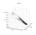
- FIG. 3 is a diagram illustrating a two-dimensional (2D) look-up table.
- FIG. 4 is a block diagram illustrating a configuration of a display device according to a related art.
- FIG. 1 is a block diagram illustrating a configuration of a display device 1 according to an embodiment of the present invention.
- the display device 1 includes a target brightness-setting unit 11 , a drive circuit 12 , a backlight 13 (a “backlight” is hereinafter referred to as a “BL”), a deterioration-detecting circuit 14 , a warning screen-rendering circuit 15 , and a display unit 16 as illustrated in FIG. 1 .
- the display unit 16 is a display panel such as an LCD or a micromirror device.
- the BL 13 is a light source that illuminates the display panel.
- the target brightness-setting unit 11 sets target brightness of the BL 13 input by, for example, a switch installed in the display device 1 to the drive circuit 12 .
- the drive circuit 12 drives the BL 13 based on a BL drive value corresponding to the target brightness set by the target brightness-setting unit 11 .
- the BL drive value is a control value used to change BL brightness such as a voltage, an electric current, or a pulse width modulation (PWM) duty at the time of BL control.
- PWM pulse width modulation
- the deterioration-detecting circuit 14 includes a drive value-detecting unit 21 , a temperature-detecting unit 22 , a reference luminescence amount-acquiring unit 23 , a luminescence amount-detecting unit 25 , and a deterioration-detecting unit 26 .
- the drive value-detecting unit 21 detects the BL drive value used when the drive circuit 12 drives the BL 13 .
- the temperature-detecting unit 22 detects an internal temperature or external temperature of the display device 1 .
- the reference luminescence amount-acquiring unit 23 includes a reference luminescence amount storage unit 24 that stores data representing a relationship among the BL drive value, the temperature, and a reference luminescence amount.
- reference brightness is used as the reference luminescence amount.
- the reference brightness is brightness used as a reference for determining a deterioration status of brightness.
- the reference luminescence amount-acquiring unit 23 obtains the reference brightness corresponding to a combination of the BL drive value detected by the drive value-detecting unit 21 and the temperature detected by the temperature-detecting unit 22 based on the data stored in the reference luminescence amount storage unit 24 .
- the luminescence amount-detecting unit 25 detects or estimates brightness as the luminescence amount of the BL 13 . Further, the luminescence amount-detecting unit 25 performs brightness stabilization control of notifying the drive circuit 12 of a new BL drive value so that brightness can be constant based on a current brightness.
- the deterioration-detecting unit 26 calculates a status value representing a status of a display characteristic by comparing the reference brightness calculated by the reference luminescence amount-acquiring unit 23 with the brightness detected by the luminescence amount-detecting unit 25 .
- the deterioration-detecting unit 26 compares a status value of an initial status with a current status value, and notifies the warning screen-rendering circuit 15 of performance deterioration when a deterioration status needing calibration is detected.
- the deterioration-detecting unit 26 includes an initial status value storage unit 27 that stores an initial value of a deterioration status.
- the warning screen-rendering circuit 15 causes a screen of a video signal input from a personal computer, a video, or the like to be displayed on the display unit 16 without change.
- the warning screen-rendering circuit 15 causes a warning screen superimposed on the screen of the video signal to be displayed on the display unit 16 .
- the target brightness-setting unit 11 , the drive circuit 12 , the BL 13 , the warning screen-rendering circuit 15 , and the display unit 16 are implemented by an existing common technique.
- a method of detecting brightness of the BL 13 at the side or back of the display panel (the display unit 16 ) is employed.
- the same effect is obtained even when screen brightness is detected by the luminescence amount-detecting unit 25 installed on the display screen of the display panel (the display unit 16 ).
- brightness is used as the luminescence amount, but a measure of the luminescence amount can be appropriately selected according to a luminescence amount-detecting means equipped in the luminescence amount-detecting unit 25 .
- RGB red, green, and blue
- luminance sensor value may be used instead of brightness.
- a manufacturer of the display device 1 measures a brightness characteristic using the display device 1 in advance when the BL drive value and the temperature are changed. This is because the BL 13 has a characteristic in which brightness significantly changes depending on the BL drive value and the temperature.
- FIG. 2 is a diagram illustrating a brightness characteristic corresponding to a change in the ambient temperature and the BL drive value.
- FIG. 2 illustrates an example in which a PWM duty is used as the BL drive value.
- FIG. 2 illustrates a relationship between the BL drive value and the reference brightness that is brightness when the drive circuit 12 drives the BL 13 based on the BL drive value for each ambient temperature of 15° C., 25° C., and 35° C.
- FIG. 3 is a diagram illustrating a 2D look-up table (hereinafter referred to as a “2DLUT”) generated from the relationship among the temperature, the BL drive value, and the reference brightness illustrated in FIG. 2 .
- the 2DLUT is data representing a correspondence between a set of the temperature (TEMP) and the BL drive value (BL Level) and the reference brightness (Lumi) as illustrated in FIG. 3 .
- the manufacturer of the display device 1 generates the 2DLUT illustrated in FIG. 3 based on the brightness characteristic obtained as in FIG. 2 .
- the generated 2DLUT is stored in the reference luminescence amount storage unit 24 of the display device 1 .
- initial characteristics of the display device 1 are stored at a point in time directly after calibration, for example, when produced in a factory.
- the point in time directly after calibration is referred to as a “time of initial characteristic setting.”
- the drive value-detecting unit 21 of the display device 1 reads the BL drive value at the time of initial characteristic setting from the drive circuit 12 , and outputs the read BL drive value to the reference luminescence amount-acquiring unit 23 .
- the temperature-detecting unit 22 reads the temperature at the time of initial characteristic setting, and outputs the read temperature to the reference luminescence amount-acquiring unit 23 .
- the reference luminescence amount-acquiring unit 23 reads the reference brightness from the 2DLUT ( FIG. 3 ) stored in the reference luminescence amount storage unit 24 in advance using the received temperature and the BL drive value as search conditions.
- the reference luminescence amount-acquiring unit 23 outputs the read reference brightness to the deterioration-detecting unit 26 .
- the deterioration-detecting unit 26 acquires the brightness of the BL 13 at the time of initial characteristic setting from the luminescence amount-detecting unit 25 .
- the deterioration-detecting unit 26 calculates a ratio of the reference brightness obtained from the 2DLUT by the reference luminescence amount-acquiring unit 23 using the temperature and the drive value at the time of initial characteristic setting and the brightness at the time of initial characteristic setting received from the luminescence amount-detecting unit 25 .
- the deterioration-detecting unit 26 writes the calculated ratio in the initial status value storage unit 27 as the initial status value (InitStatus).
- the performance deterioration detection process is periodically performed at certain time intervals.
- the drive value-detecting unit 21 of the display device 1 reads the current BL drive value from the drive circuit 12 , and outputs the current BL drive value to the reference luminescence amount-acquiring unit 23 .
- the temperature-detecting unit 22 reads the current temperature, and outputs the current temperature to the reference luminescence amount-acquiring unit 23 .
- the reference luminescence amount-acquiring unit 23 reads the reference brightness from the 2DLUT ( FIG. 3 ) stored in the reference luminescence amount storage unit 24 in advance using the received temperature and the BL drive value as the search conditions.
- the reference luminescence amount-acquiring unit 23 outputs the read reference brightness to the deterioration-detecting unit 26 .
- the deterioration-detecting unit 26 acquires the current brightness of the BL 13 from the luminescence amount-detecting unit 25 .
- the deterioration-detecting unit 26 calculates a current status value (CurrentStatus) that is a ratio of the reference brightness obtained from the 2DLUT by the reference luminescence amount-acquiring unit 23 using the current temperature and the BL drive value and the current brightness received from the luminescence amount-detecting unit 25 .
- CurrentStatus CurrentStatus
- the performance retention rate is a deterioration detection value that becomes 100% directly after calibration and serves as an index that decreases as deterioration of the display device 1 progresses.
- the deterioration-detecting unit 26 determines that calibration is required when the calculated performance retention rate is lower than a predetermined permissible limit (threshold value), and outputs the warning output instruction to the warning screen-rendering circuit 15 .
- the warning screen-rendering circuit 15 notifies of performance deterioration of a display characteristic, and causes a warning screen warning that calibration is required to be displayed on the display unit 16 .
- the display device 1 displays the warning screen on the display unit 16 , and urges the user to calibrate the display device 1 .
- the warning screen is displayed when the display device 1 is used for about 1000 to 2000 hours after calibration.
- the performance retention rate of the display device 1 is detected based on a change in luminance efficiency of the BL 13 .
- the display device 1 can suggest calibration only when certain performance deterioration is detected.
- the present embodiment has advantages in that the performance retention rate can be detected even when the brightness stabilization control is performed, and the performance retention rate is constant even when the ambient temperature or the display brightness changes at the time of measurement. For example, the performance retention rate becomes 100% directly after calibration regardless of a brightness setting, and thus the performance retention rate can be accurately detected even at a brightness different from that at the time of calibration.
- a display device including a display panel (display unit) such as an LCD or a micromirror device, a light source (BL) that illuminates a display panel, and a control unit (drive circuit) that controls a luminescence amount of the light source
- a drive value-detecting unit detects a drive value (a BL drive value) used to control a luminescence amount of the light source of its own display device by the control unit
- a temperature-detecting unit detects an internal temperature or external temperature of the display device.
- a luminescence amount-detecting unit detects or estimates a luminescence amount (brightness) of the light source or the display panel.
- a reference luminescence amount-acquiring unit obtains a reference luminescence amount (reference brightness) of the light source corresponding to the drive value detected by the drive value-detecting unit and the temperature detected by the temperature-detecting unit.
- a deterioration-detecting unit calculates an initial status value based on a ratio of the reference luminescence amount obtained based on a temperature and a drive value in an initial status by the reference luminescence amount-acquiring unit and a luminescence amount in the initial status detected by the luminescence amount-detecting unit, and stores the initial status value.
- the deterioration-detecting unit further calculates a current status value based on a ratio of a reference luminescence amount obtained based on a current temperature and drive value by the reference luminescence amount-acquiring unit and a current luminescence amount detected by the luminescence amount-detecting unit, compares the stored initial status value with the calculated current status value, and determines whether calibration is required.
- a warning screen display unit causes deterioration of the display device or the light source to be displayed on the display panel based on the determination. Through this operation, the display device reports performance deterioration of a display characteristic to the user.
- the reference luminescence amount-acquiring unit 23 uses the 2DLUT illustrated in FIG. 3 in order to obtain the reference brightness, but may calculate the reference brightness using a certain calculation formula.
- the calculation formula is a formula for calculating the reference brightness based on the temperature and the BL drive value using a polynomial expansion that approximates the characteristics represented by the 2DLUT.
- the reference brightness output by the reference luminescence amount-acquiring unit 23 may be absolute brightness, a proportion of certain brightness used as a reference, or relative brightness.
- the 2DLUT is data representing a correspondence between a set of the temperature and the BL drive value and the relative brightness.
- the reference luminescence amount-acquiring unit 23 calculates the relative brightness based on the temperature and the BL drive value using a polynomial expansion that approximates the characteristics represented by the 2DLUT.
- the reference brightness preferably has a drive level that is small in a brightness change even when the temperature changes.
- a circular portion indicated by a dotted line is small in a brightness change caused by the temperature.
- the brightness of the BL 13 when the drive circuit 12 is driven based on the BL drive value indicated by the circular portion is used as the reference brightness.
- the relative brightness when used, it is desirable to perform normalization at a drive level that is small in brightness change even when the temperature changes.
- the circular portion indicated by the dotted line is small in a brightness change caused by the temperature.
- the brightness of the BL 13 when the drive circuit 12 is driven based on the BL drive value indicated by the circular portion is used as the relative brightness.
- the performance deterioration is reported to the user, but conversely, a normal status may be reported at a normal time.
- the reference luminescence amount-acquiring unit 23 obtains the reference brightness corresponding to the detected temperature and the BL drive value, and the deterioration-detecting unit 26 compares the reference brightness with the brightness of the BL detected when the temperature and the BL drive value are detected.
- the same effects are obtained even when, conversely, the reference brightness is fixed, and the current brightness is corrected to correspond to the temperature and the BL drive value at the reference brightness.
- the display device according to the present embodiment has the following advantages.
- a deterioration status value changes according to a deterioration status of an actual display characteristic of a display device. In other words, since deterioration progresses rapidly at high brightness or high ambient temperature even when an operating time is the same, the deterioration status value significantly changes.
- a deterioration detection value (a threshold value of a deterioration status value) used to determine that calibration is required is constant without depending on an ambient temperature or display brightness at the time of detection.
- the present invention can be applied to various display devices such as projectors or LCDs.
- One of an extra-high pressure mercury lamp, a W/RGB light emitting diode (LED), and a cold cathode fluorescent lamp (CCFL) can be selected as the backlight.
- the luminescence amount-detecting unit 25 may detect screen brightness or may detect backlight brightness at the side or back of the screen.
- the luminescence amount detected by the luminescence amount-detecting unit 25 may be replaced with another measure representing a luminescence amount such as an RGB value of a color sensor or a luminance value instead of brightness. For example, in a display device having a multi-color backlight, an RGB value of a color sensor is appropriate.
- the display device according to the present embodiment is appropriate for display devices used in industries in which high-accuracy color reproduction is required such as displays for graphic design use or displays for medical use.
- the deterioration-detecting circuit 14 illustrated in FIG. 1 is implemented by dedicated hardware (for example, a wired logic or the like). Further, a part of the deterioration-detecting circuit 14 may be configured with a memory and a central processing unit (CPU), and the respective functions thereof may be implemented by loading a program for implementing the respective functions from the memory and executing the program.
- dedicated hardware for example, a wired logic or the like.
- CPU central processing unit
- the program may be transmitted from a computer system in which the program is stored in a storage device or the like to another computer system via a transmission medium or a transmission wave in a transmission medium.
- the “transmission medium” for transmitting the program is a medium having a function of transmitting information such as a network (communication network) such as the Internet or a communication line such as a telephone line.
- the program may be one which implements part of the above-described function.
- the program may be one which implements the above-described function in combination with a program stored in a computer in advance or a differential file (differential program).
Abstract
Description
Performance retention rate [%]=current status value/initial status value (1)
Claims (4)
Applications Claiming Priority (1)
| Application Number | Priority Date | Filing Date | Title |
|---|---|---|---|
| PCT/JP2011/072368 WO2013046392A1 (en) | 2011-09-29 | 2011-09-29 | Deterioration detecting circuit, display device, and performance deterioration detecting method |
Publications (2)
| Publication Number | Publication Date |
|---|---|
| US20140240377A1 US20140240377A1 (en) | 2014-08-28 |
| US9236013B2 true US9236013B2 (en) | 2016-01-12 |
Family
ID=47994499
Family Applications (1)
| Application Number | Title | Priority Date | Filing Date |
|---|---|---|---|
| US14/347,610 Active 2031-10-23 US9236013B2 (en) | 2011-09-29 | 2011-09-29 | Display device for detecting deterioration based on detected temperature and backlight luminescence |
Country Status (3)
| Country | Link |
|---|---|
| US (1) | US9236013B2 (en) |
| JP (1) | JP5721198B2 (en) |
| WO (1) | WO2013046392A1 (en) |
Families Citing this family (7)
| Publication number | Priority date | Publication date | Assignee | Title |
|---|---|---|---|---|
| US9495332B2 (en) * | 2012-12-21 | 2016-11-15 | International Business Machines Corporation | Detection and repositioning of pop-up dialogs |
| US9459141B2 (en) * | 2014-03-11 | 2016-10-04 | Getac Technology Corporation | Brightness control apparatus and brightness control method |
| KR20160007825A (en) * | 2014-07-02 | 2016-01-21 | 삼성디스플레이 주식회사 | Degradation detecting method and degradation detecting device of display panel |
| KR102313360B1 (en) * | 2014-11-10 | 2021-10-18 | 삼성디스플레이 주식회사 | Organic Light Emitting Display Device and Driving Method Thereof |
| CN105047141B (en) * | 2015-08-17 | 2017-08-11 | 青岛海信电器股份有限公司 | Split screen detection method, device and the LCD TV of multi partition dynamic backlight |
| CN108831357A (en) * | 2018-05-02 | 2018-11-16 | 广州市统云网络科技有限公司 | A kind of LED display working condition automated measurement &control method |
| KR20210030680A (en) * | 2019-09-10 | 2021-03-18 | 삼성전자주식회사 | Display apparatus and controlling method thereof |
Citations (8)
| Publication number | Priority date | Publication date | Assignee | Title |
|---|---|---|---|---|
| JPH11305195A (en) | 1998-04-21 | 1999-11-05 | Alpine Electronics Inc | Method for indicating replacement time of back light lamp |
| JP2005331644A (en) | 2004-05-19 | 2005-12-02 | Mitsubishi Electric Corp | Image display device and image display method |
| US20080151144A1 (en) * | 2006-12-26 | 2008-06-26 | Sony Corporation | Liquid crystal display device |
| US20080246927A1 (en) * | 2007-04-09 | 2008-10-09 | Sanyo Electric Co., Ltd. | Projection display apparatus |
| JP2009093098A (en) | 2007-10-12 | 2009-04-30 | Funai Electric Co Ltd | Liquid crystal display device |
| JP2010096943A (en) | 2008-10-16 | 2010-04-30 | Epson Imaging Devices Corp | Display device and electronic apparatus |
| US20100141669A1 (en) * | 2005-09-26 | 2010-06-10 | Mitsubishi Electric Corporation | Display Apparatus |
| US20110109655A1 (en) * | 2008-08-08 | 2011-05-12 | Daisuke Takeda | Backlight and display device using the same |
-
2011
- 2011-09-29 WO PCT/JP2011/072368 patent/WO2013046392A1/en active Application Filing
- 2011-09-29 US US14/347,610 patent/US9236013B2/en active Active
- 2011-09-29 JP JP2013535739A patent/JP5721198B2/en active Active
Patent Citations (9)
| Publication number | Priority date | Publication date | Assignee | Title |
|---|---|---|---|---|
| JPH11305195A (en) | 1998-04-21 | 1999-11-05 | Alpine Electronics Inc | Method for indicating replacement time of back light lamp |
| JP3559161B2 (en) | 1998-04-21 | 2004-08-25 | アルパイン株式会社 | How to indicate when to replace the backlight lamp |
| JP2005331644A (en) | 2004-05-19 | 2005-12-02 | Mitsubishi Electric Corp | Image display device and image display method |
| US20100141669A1 (en) * | 2005-09-26 | 2010-06-10 | Mitsubishi Electric Corporation | Display Apparatus |
| US20080151144A1 (en) * | 2006-12-26 | 2008-06-26 | Sony Corporation | Liquid crystal display device |
| US20080246927A1 (en) * | 2007-04-09 | 2008-10-09 | Sanyo Electric Co., Ltd. | Projection display apparatus |
| JP2009093098A (en) | 2007-10-12 | 2009-04-30 | Funai Electric Co Ltd | Liquid crystal display device |
| US20110109655A1 (en) * | 2008-08-08 | 2011-05-12 | Daisuke Takeda | Backlight and display device using the same |
| JP2010096943A (en) | 2008-10-16 | 2010-04-30 | Epson Imaging Devices Corp | Display device and electronic apparatus |
Non-Patent Citations (1)
| Title |
|---|
| International Search Report in PCT/JP2011/072368 dated Dec. 27, 2011 (English Translation Thereof). |
Also Published As
| Publication number | Publication date |
|---|---|
| WO2013046392A1 (en) | 2013-04-04 |
| JPWO2013046392A1 (en) | 2015-03-26 |
| JP5721198B2 (en) | 2015-05-20 |
| US20140240377A1 (en) | 2014-08-28 |
Similar Documents
| Publication | Publication Date | Title |
|---|---|---|
| US9236013B2 (en) | Display device for detecting deterioration based on detected temperature and backlight luminescence | |
| US7131731B2 (en) | Projection type video display apparatus | |
| US20180240398A1 (en) | Light-emitting diode display device | |
| US20090033591A1 (en) | Liquid crystal display | |
| US9022573B2 (en) | Image display device and light source cooling method | |
| US20120218175A1 (en) | Image display apparatus and control method therefor | |
| US9779648B2 (en) | Display device for correcting white balance based on degradation and chromaticity control method thereof | |
| JP2012073400A (en) | Display device | |
| US8850714B2 (en) | Chromaticity correction device, chromaticity correction method, and display device | |
| JP5082614B2 (en) | Backlight control device, liquid crystal display device, light emitter control device, and backlight control method | |
| JP2013004263A (en) | Backlight device, control method of the same and picture display apparatus | |
| US10186210B2 (en) | Image display device and control methods for image display device | |
| JP2017032889A (en) | LED display device | |
| JPWO2012017541A1 (en) | Image display device and light source cooling method | |
| KR102030801B1 (en) | Liquid crystal display apparatus with managing life cycle of back light | |
| JP2017032890A (en) | LED display device | |
| JP2013222064A (en) | Laser light source projector | |
| JP2012181466A (en) | Liquid crystal panel device | |
| JP5354699B2 (en) | Chromaticity correction circuit, display device, and chromaticity correction method | |
| JP2013097115A (en) | Liquid crystal display device and control method for the same | |
| JP6641028B2 (en) | Brightness adjusting device, display device and brightness adjusting method | |
| JP5665147B2 (en) | Chromaticity correction circuit, display device, and chromaticity correction method | |
| JP2015081996A (en) | Display device, control method and program of display device | |
| US20210310859A1 (en) | Light amount measurement device and control method therefor | |
| JP2016080753A (en) | Light source device, image display device, control method of light source device, and program |
Legal Events
| Date | Code | Title | Description |
|---|---|---|---|
| AS | Assignment |
Owner name: NEC DISPLAY SOLUTIONS, LTD, JAPAN Free format text: ASSIGNMENT OF ASSIGNORS INTEREST;ASSIGNOR:MATSUI, KATSUYUKI;REEL/FRAME:032565/0452 Effective date: 20140320 |
|
| STCF | Information on status: patent grant |
Free format text: PATENTED CASE |
|
| MAFP | Maintenance fee payment |
Free format text: PAYMENT OF MAINTENANCE FEE, 4TH YEAR, LARGE ENTITY (ORIGINAL EVENT CODE: M1551); ENTITY STATUS OF PATENT OWNER: LARGE ENTITY Year of fee payment: 4 |
|
| AS | Assignment |
Owner name: SHARP NEC DISPLAY SOLUTIONS, LTD., JAPAN Free format text: CHANGE OF NAME;ASSIGNOR:NEC DISPLAY SOLUTIONS, LTD.;REEL/FRAME:055256/0755 Effective date: 20201101 |
|
| MAFP | Maintenance fee payment |
Free format text: PAYMENT OF MAINTENANCE FEE, 8TH YEAR, LARGE ENTITY (ORIGINAL EVENT CODE: M1552); ENTITY STATUS OF PATENT OWNER: LARGE ENTITY Year of fee payment: 8 |