US9232932B2 - Providing motion mode image in ultrasound system - Google Patents
Providing motion mode image in ultrasound system Download PDFInfo
- Publication number
- US9232932B2 US9232932B2 US13/620,619 US201213620619A US9232932B2 US 9232932 B2 US9232932 B2 US 9232932B2 US 201213620619 A US201213620619 A US 201213620619A US 9232932 B2 US9232932 B2 US 9232932B2
- Authority
- US
- United States
- Prior art keywords
- ultrasound
- signals
- reception
- mode image
- living body
- Prior art date
- Legal status (The legal status is an assumption and is not a legal conclusion. Google has not performed a legal analysis and makes no representation as to the accuracy of the status listed.)
- Active, expires
Links
Images


Classifications
-
- A—HUMAN NECESSITIES
- A61—MEDICAL OR VETERINARY SCIENCE; HYGIENE
- A61B—DIAGNOSIS; SURGERY; IDENTIFICATION
- A61B8/00—Diagnosis using ultrasonic, sonic or infrasonic waves
- A61B8/13—Tomography
- A61B8/14—Echo-tomography
-
- A—HUMAN NECESSITIES
- A61—MEDICAL OR VETERINARY SCIENCE; HYGIENE
- A61B—DIAGNOSIS; SURGERY; IDENTIFICATION
- A61B8/00—Diagnosis using ultrasonic, sonic or infrasonic waves
- A61B8/06—Measuring blood flow
-
- A—HUMAN NECESSITIES
- A61—MEDICAL OR VETERINARY SCIENCE; HYGIENE
- A61B—DIAGNOSIS; SURGERY; IDENTIFICATION
- A61B8/00—Diagnosis using ultrasonic, sonic or infrasonic waves
- A61B8/46—Ultrasonic, sonic or infrasonic diagnostic devices with special arrangements for interfacing with the operator or the patient
- A61B8/461—Displaying means of special interest
- A61B8/463—Displaying means of special interest characterised by displaying multiple images or images and diagnostic data on one display
-
- A—HUMAN NECESSITIES
- A61—MEDICAL OR VETERINARY SCIENCE; HYGIENE
- A61B—DIAGNOSIS; SURGERY; IDENTIFICATION
- A61B8/00—Diagnosis using ultrasonic, sonic or infrasonic waves
- A61B8/46—Ultrasonic, sonic or infrasonic diagnostic devices with special arrangements for interfacing with the operator or the patient
- A61B8/467—Ultrasonic, sonic or infrasonic diagnostic devices with special arrangements for interfacing with the operator or the patient characterised by special input means
- A61B8/469—Ultrasonic, sonic or infrasonic diagnostic devices with special arrangements for interfacing with the operator or the patient characterised by special input means for selection of a region of interest
-
- A—HUMAN NECESSITIES
- A61—MEDICAL OR VETERINARY SCIENCE; HYGIENE
- A61B—DIAGNOSIS; SURGERY; IDENTIFICATION
- A61B8/00—Diagnosis using ultrasonic, sonic or infrasonic waves
- A61B8/48—Diagnostic techniques
- A61B8/486—Diagnostic techniques involving arbitrary m-mode
-
- A—HUMAN NECESSITIES
- A61—MEDICAL OR VETERINARY SCIENCE; HYGIENE
- A61B—DIAGNOSIS; SURGERY; IDENTIFICATION
- A61B8/00—Diagnosis using ultrasonic, sonic or infrasonic waves
- A61B8/48—Diagnostic techniques
- A61B8/488—Diagnostic techniques involving Doppler signals
-
- A—HUMAN NECESSITIES
- A61—MEDICAL OR VETERINARY SCIENCE; HYGIENE
- A61B—DIAGNOSIS; SURGERY; IDENTIFICATION
- A61B8/00—Diagnosis using ultrasonic, sonic or infrasonic waves
- A61B8/52—Devices using data or image processing specially adapted for diagnosis using ultrasonic, sonic or infrasonic waves
- A61B8/5215—Devices using data or image processing specially adapted for diagnosis using ultrasonic, sonic or infrasonic waves involving processing of medical diagnostic data
- A61B8/5238—Devices using data or image processing specially adapted for diagnosis using ultrasonic, sonic or infrasonic waves involving processing of medical diagnostic data for combining image data of patient, e.g. merging several images from different acquisition modes into one image
- A61B8/5246—Devices using data or image processing specially adapted for diagnosis using ultrasonic, sonic or infrasonic waves involving processing of medical diagnostic data for combining image data of patient, e.g. merging several images from different acquisition modes into one image combining images from the same or different imaging techniques, e.g. color Doppler and B-mode
-
- G—PHYSICS
- G01—MEASURING; TESTING
- G01S—RADIO DIRECTION-FINDING; RADIO NAVIGATION; DETERMINING DISTANCE OR VELOCITY BY USE OF RADIO WAVES; LOCATING OR PRESENCE-DETECTING BY USE OF THE REFLECTION OR RERADIATION OF RADIO WAVES; ANALOGOUS ARRANGEMENTS USING OTHER WAVES
- G01S15/00—Systems using the reflection or reradiation of acoustic waves, e.g. sonar systems
- G01S15/88—Sonar systems specially adapted for specific applications
- G01S15/89—Sonar systems specially adapted for specific applications for mapping or imaging
- G01S15/8906—Short-range imaging systems; Acoustic microscope systems using pulse-echo techniques
- G01S15/8979—Combined Doppler and pulse-echo imaging systems
- G01S15/8984—Measuring the velocity vector
-
- G—PHYSICS
- G01—MEASURING; TESTING
- G01S—RADIO DIRECTION-FINDING; RADIO NAVIGATION; DETERMINING DISTANCE OR VELOCITY BY USE OF RADIO WAVES; LOCATING OR PRESENCE-DETECTING BY USE OF THE REFLECTION OR RERADIATION OF RADIO WAVES; ANALOGOUS ARRANGEMENTS USING OTHER WAVES
- G01S7/00—Details of systems according to groups G01S13/00, G01S15/00, G01S17/00
- G01S7/52—Details of systems according to groups G01S13/00, G01S15/00, G01S17/00 of systems according to group G01S15/00
- G01S7/52017—Details of systems according to groups G01S13/00, G01S15/00, G01S17/00 of systems according to group G01S15/00 particularly adapted to short-range imaging
- G01S7/52085—Details related to the ultrasound signal acquisition, e.g. scan sequences
-
- G—PHYSICS
- G06—COMPUTING; CALCULATING OR COUNTING
- G06T—IMAGE DATA PROCESSING OR GENERATION, IN GENERAL
- G06T7/00—Image analysis
- G06T7/20—Analysis of motion
-
- G—PHYSICS
- G10—MUSICAL INSTRUMENTS; ACOUSTICS
- G10K—SOUND-PRODUCING DEVICES; METHODS OR DEVICES FOR PROTECTING AGAINST, OR FOR DAMPING, NOISE OR OTHER ACOUSTIC WAVES IN GENERAL; ACOUSTICS NOT OTHERWISE PROVIDED FOR
- G10K11/00—Methods or devices for transmitting, conducting or directing sound in general; Methods or devices for protecting against, or for damping, noise or other acoustic waves in general
- G10K11/18—Methods or devices for transmitting, conducting or directing sound
- G10K11/26—Sound-focusing or directing, e.g. scanning
- G10K11/34—Sound-focusing or directing, e.g. scanning using electrical steering of transducer arrays, e.g. beam steering
-
- A—HUMAN NECESSITIES
- A61—MEDICAL OR VETERINARY SCIENCE; HYGIENE
- A61B—DIAGNOSIS; SURGERY; IDENTIFICATION
- A61B8/00—Diagnosis using ultrasonic, sonic or infrasonic waves
- A61B8/08—Detecting organic movements or changes, e.g. tumours, cysts, swellings
- A61B8/0883—Detecting organic movements or changes, e.g. tumours, cysts, swellings for diagnosis of the heart
-
- A—HUMAN NECESSITIES
- A61—MEDICAL OR VETERINARY SCIENCE; HYGIENE
- A61B—DIAGNOSIS; SURGERY; IDENTIFICATION
- A61B8/00—Diagnosis using ultrasonic, sonic or infrasonic waves
- A61B8/08—Detecting organic movements or changes, e.g. tumours, cysts, swellings
- A61B8/0891—Detecting organic movements or changes, e.g. tumours, cysts, swellings for diagnosis of blood vessels
-
- A—HUMAN NECESSITIES
- A61—MEDICAL OR VETERINARY SCIENCE; HYGIENE
- A61B—DIAGNOSIS; SURGERY; IDENTIFICATION
- A61B8/00—Diagnosis using ultrasonic, sonic or infrasonic waves
- A61B8/44—Constructional features of the ultrasonic, sonic or infrasonic diagnostic device
- A61B8/4483—Constructional features of the ultrasonic, sonic or infrasonic diagnostic device characterised by features of the ultrasound transducer
-
- A—HUMAN NECESSITIES
- A61—MEDICAL OR VETERINARY SCIENCE; HYGIENE
- A61B—DIAGNOSIS; SURGERY; IDENTIFICATION
- A61B8/00—Diagnosis using ultrasonic, sonic or infrasonic waves
- A61B8/52—Devices using data or image processing specially adapted for diagnosis using ultrasonic, sonic or infrasonic waves
- A61B8/5207—Devices using data or image processing specially adapted for diagnosis using ultrasonic, sonic or infrasonic waves involving processing of raw data to produce diagnostic data, e.g. for generating an image
-
- G—PHYSICS
- G01—MEASURING; TESTING
- G01S—RADIO DIRECTION-FINDING; RADIO NAVIGATION; DETERMINING DISTANCE OR VELOCITY BY USE OF RADIO WAVES; LOCATING OR PRESENCE-DETECTING BY USE OF THE REFLECTION OR RERADIATION OF RADIO WAVES; ANALOGOUS ARRANGEMENTS USING OTHER WAVES
- G01S7/00—Details of systems according to groups G01S13/00, G01S15/00, G01S17/00
- G01S7/52—Details of systems according to groups G01S13/00, G01S15/00, G01S17/00 of systems according to group G01S15/00
- G01S7/52017—Details of systems according to groups G01S13/00, G01S15/00, G01S17/00 of systems according to group G01S15/00 particularly adapted to short-range imaging
- G01S7/52053—Display arrangements
- G01S7/52057—Cathode ray tube displays
- G01S7/52074—Composite displays, e.g. split-screen displays; Combination of multiple images or of images and alphanumeric tabular information
Definitions
- the present disclosure generally relates to ultrasound systems, and more particularly to providing a motion mode image in an ultrasound system.
- An ultrasound system has become an important and popular diagnostic tool since it has a wide range of applications. Specifically, due to its non-invasive and non-destructive nature, the ultrasound system has been extensively used in the medical profession. Modern high-performance ultrasound systems and techniques are commonly used to produce two-dimensional or three-dimensional ultrasound images of internal features of target objects (e.g., human organs).
- target objects e.g., human organs
- the ultrasound system may provide ultrasound images of various modes including a brightness mode image representing reflection coefficients of ultrasound signals (i.e., ultrasound echo signals) reflected from a target object of a living body with a two-dimensional image, a Doppler mode image representing velocity of a moving target object with spectral Doppler by using a Doppler effect, a color Doppler mode image representing velocity of the moving target object with colors by using the Doppler effect, an elastic image representing mechanical characteristics of tissues before and after applying compression thereto, etc.
- a brightness mode image representing reflection coefficients of ultrasound signals (i.e., ultrasound echo signals) reflected from a target object of a living body with a two-dimensional image
- a Doppler mode image representing velocity of a moving target object with spectral Doppler by using a Doppler effect
- a color Doppler mode image representing velocity of the moving target object with colors by using the Doppler effect
- an elastic image representing mechanical characteristics of tissues before and after applying compression thereto, etc.
- the ultrasound system may transmit ultrasound signals to the living body including a moving target object (e.g., blood flow) and receive ultrasound signals (i.e., ultrasound echo signals) from the living body.
- the ultrasound system may further form the color Doppler mode image representing velocities of the target object with colors based on the ultrasound echo signals.
- the color Doppler image may be used to diagnose disease of a blood vessel, a heart and the like.
- the color Doppler image may not represent an accurate motion of the target object since the respective colors in the color Doppler image indicate the velocity of the target object, which moves forward in a transmission direction of the ultrasound signals and backward in the transmission direction of the ultrasound signals.
- vector Doppler methods capable of obtaining motion (i.e., velocity and direction) of the target object are used.
- a cross beam-based method of the vector Doppler methods acquires velocity components of the target object from at least two different directions, and combines the velocity components to form vector information including two-dimensional or three-dimensional direction information and velocity information.
- an ultrasound system comprises: a user input unit configured to receive input information for setting a region of interest on a brightness mode image; and a processing unit configured to form the brightness mode image based on first ultrasound data corresponding to a target object, and form vector information of the target object based on second ultrasound data corresponding to the target object, the processing unit being further configured to form a motion mode image including at least one of a brightness motion mode image and a color motion mode image based on the first ultrasound data and the vector information corresponding to the region of interest.
- a method of providing a motion mode image comprising: a) forming a brightness mode image based on first ultrasound data corresponding to a target object; b) forming vector information of the target object based on second ultrasound data corresponding to the target object; c) receiving input information for setting a region of interest on the brightness mode image; and d) forming a motion mode image including at least one of a brightness motion mode image and a color motion mode image based on the first ultrasound data and the vector information corresponding to the region of interest.
- FIG. 1 is a block diagram showing an illustrative embodiment of an ultrasound system.
- FIG. 2 is a schematic diagram showing an example of a brightness mode image and a region of interest.
- FIG. 3 is a block diagram showing an illustrative embodiment of an ultrasound data acquiring unit.
- FIGS. 4 to 7 are schematic diagrams showing examples of transmission directions and reception directions.
- FIG. 8 is a schematic diagram showing an example of sampling data and pixels of an ultrasound image.
- FIGS. 9 to 12 are schematic diagrams showing examples of performing a receiving beam-forming.
- FIG. 13 is a schematic diagram showing an example of setting weights.
- FIG. 14 is a schematic diagram showing an example of setting a sampling data set.
- FIG. 15 is a flow chart showing a process of forming a motion mode image.
- FIG. 16 is a schematic diagram showing an example of the transmission directions, the reception directions, the vector information and an over-determined problem.
- FIGS. 17 and 18 are schematic diagrams showing examples of motion mode images.
- the ultrasound system 100 may include a user input unit 110 .
- the user input unit 110 may be configured to receive input information from a user.
- the input information may include first input information for setting a first region of interest ROI on a brightness mode image BI, as shown in FIG. 2 .
- the first region of interest ROI may include a color box for obtaining vector information corresponding to motion (i.e., velocity and direction) of a target object.
- the input information may further include second input information for setting a second region of interest VML on the brightness mode image BI, as shown in FIGS. 17 and 18 .
- the second region of interest VML may be a region of interest for obtaining a motion mode image.
- the second region of interest VML may be a straight line or a curve.
- the motion mode image may be an image for representing how biological information of the target object varies with time based on at least one of vector information and ultrasound data of the target object.
- a reference numeral BV represents a blood vessel.
- the user input unit 110 may include a control panel, a track ball, a mouse, a keyboard and the like.
- the ultrasound system 100 may further include an ultrasound data acquiring unit 120 .
- the ultrasound data acquiring unit 120 may be configured to transmit ultrasound signals to a living body.
- the living body may include moving target objects (e.g., blood vessel, heart, blood flow, etc.).
- the ultrasound data acquiring unit 120 may be further configured to receive ultrasound signals (i.e., ultrasound echo signals) from the living body to acquire ultrasound data corresponding to an ultrasound image.
- FIG. 3 is a block diagram showing an illustrative embodiment of the ultrasound data acquiring unit.
- the ultrasound data acquiring unit 120 may include an ultrasound probe 310 .
- the ultrasound probe 310 may include a plurality of elements 311 (see FIG. 4 ) for reciprocally converting between ultrasound signals and electrical signals.
- the ultrasound probe 310 may be configured to transmit the ultrasound signals to the living body.
- the ultrasound signals transmitted from the ultrasound probe 310 may be plane wave signals that the ultrasound signals are not focused at a focusing point or focused signals that the ultrasound signals are focused at the focusing point. However, it should be noted herein that the ultrasound signals may not be limited thereto.
- the ultrasound probe 310 may be further configured to receive the ultrasound echo signals from the living body to output electrical signals (hereinafter, referred to as “reception signals”).
- the reception signals may be analog signals.
- the ultrasound probe 310 may include a convex probe, a linear probe and the like.
- the ultrasound data acquiring unit 120 may further include a transmitting section 320 .
- the transmitting section 320 may be configured to control the transmission of the ultrasound signals.
- the transmitting section 320 may be further configured to generate electrical signals (hereinafter, referred to as “transmission signals”) in consideration of the elements 311 .
- the transmitting section 320 may be configured to generate transmission signals (hereinafter, referred to as “brightness mode transmission signals”) for obtaining the brightness mode image BI in consideration of the elements 311 .
- the ultrasound probe 310 may be configured to convert the brightness mode transmission signals provided from the transmitting section 320 into the ultrasound signals, transmit the ultrasound signals to the living body, and receive the ultrasound echo signals from the living body to output reception signals (hereinafter, referred to as “brightness mode reception signals”).
- the transmitting section 320 may be further configured to generate transmission signals (hereinafter, referred to as “Doppler mode transmission signals”) corresponding to an ensemble number in consideration of the elements 311 and at least one transmission direction of the ultrasound signals (i.e., transmission beam).
- Doppler mode transmission signals transmission signals
- the ultrasound probe 310 may be configured to convert the Doppler mode transmission signals provided from the transmitting section 320 into the ultrasound signals, transmit the ultrasound signals to the living body in the at least one transmission direction, and receive the ultrasound echo signals from the living body to output reception signals (hereinafter, referred to as “Doppler mode reception signals”).
- the ensemble number may represent the number of transmitting and receiving the ultrasound signals to/from a target object.
- the transmitting section 320 may be configured to generate the Doppler mode transmission signals corresponding to the ensemble number in consideration of a transmission direction Tx and the elements 311 , as shown in FIG. 4 .
- the transmission direction may be one direction in the range of a direction (0 degree) perpendicular to a longitudinal direction of the elements 311 to a maximum steering direction of the transmission beam.
- the transmitting section 320 may be configured to generate first Doppler mode transmission signals corresponding to the ensemble number in consideration of a first transmission direction Tx 1 and the elements 311 , as shown in FIG. 5 .
- the ultrasound probe 310 may be configured to convert the first Doppler mode transmission signals provided from the transmitting section 320 into the ultrasound signals, transmit the ultrasound signals to the living body in the first transmission direction Tx 1 , and receive the ultrasound echo signals from the living body to output first Doppler mode reception signals.
- the transmitting section 320 may be further configured to generate second Doppler mode transmission signals corresponding to the ensemble number in consideration of a second transmission direction Tx 2 and the elements 311 , as shown in FIG. 5 .
- the ultrasound probe 310 may be configured to convert the second Doppler mode transmission signals provided from the transmitting section 320 into the ultrasound signals, transmit the ultrasound signals to the living body in the second transmission direction Tx 2 , and receive the ultrasound echo signals from the living body to output second Doppler mode reception signals.
- a reference numeral PRI represents a pulse repeat interval.
- the transmitting section 320 may be configured to generate the brightness mode transmission signals for obtaining the brightness mode image BI in consideration of the elements 311 .
- the ultrasound probe 310 may be configured to convert the brightness mode transmission signals provided from the transmitting section 320 into the ultrasound signals, transmit the ultrasound signals to the living body, and receive the ultrasound echo signals from the living body to output the brightness mode reception signals.
- the transmitting section 320 may be further configured to generate the Doppler mode transmission signals corresponding to the ensemble number in consideration of the at least one transmission direction and the elements 311 .
- the ultrasound probe 310 may be configured to convert the Doppler mode transmission signals provided from the transmitting section 320 into the ultrasound signals, transmit the ultrasound signals to the living body, and receive the ultrasound echo signals from the living body to output the Doppler mode reception signals.
- the ultrasound signals may be transmitted in an interleaved transmission scheme. The interleaved transmission scheme will be described below in detail.
- the transmitting section 320 may be configured to generate the first Doppler mode transmission signals in consideration of the first transmission direction Tx 1 and the elements 311 , as shown in FIG. 6 .
- the ultrasound probe 310 may be configured to convert the first Doppler mode transmission signals provided from the transmitting section 320 into the ultrasound signals, and transmit the ultrasound signals to the living body in the first transmission direction Tx 1 .
- the transmitting section 320 may be further configured to generate the second Doppler mode transmission signals in consideration of the second transmission direction Tx 2 and the elements 311 , as shown in FIG. 6 .
- the ultrasound probe 310 may be configured to convert the second Doppler mode transmission signals provided from the transmitting section 320 into the ultrasound signals, and transmit the ultrasound signals to the living body in the second transmission direction Tx 2 .
- the ultrasound probe 310 may be further configured to receive the ultrasound echo signals (i.e., ultrasound echo signals corresponding to first Doppler mode transmission signals) from the living body to output the first Doppler mode reception signals.
- the ultrasound probe 310 may be also configured to receive the ultrasound echo signals (i.e., ultrasound echo signals corresponding to second Doppler mode transmission signals) from the living body to output the second Doppler mode reception signals.
- the transmitting section 320 may be configured to generate the first Doppler mode transmission signals based on the pulse repeat interval, as shown in FIG. 6 .
- the ultrasound probe 310 may be configured to convert the first Doppler mode transmission signals provided from the transmitting section 320 into the ultrasound signals, and transmit the ultrasound signals to the living body in the first transmission direction Tx 1 .
- the transmitting section 320 may be further configured to generate the second Doppler mode transmission signals based on the pulse repeat interval, as shown in FIG. 6 .
- the ultrasound probe 310 may be configured to convert the second Doppler mode transmission signals provided from the transmitting section 320 into the ultrasound signals, and transmit the ultrasound signals to the living body in the second transmission direction Tx 2 .
- the ultrasound probe 310 may be further configured to receive the ultrasound echo signals (i.e., ultrasound echo signals corresponding to first Doppler mode transmission signals) from the living body to output the first Doppler mode reception signals.
- the ultrasound probe 310 may be also configured to receive the ultrasound echo signals (i.e., ultrasound echo signals corresponding to second Doppler mode reception signals) from the living body to output the second Doppler mode reception signals.
- the transmitting section 320 may be configured to generate the first Doppler mode transmission signals and the second Doppler mode transmission signals corresponding to the ensemble number.
- the transmitting section 320 may be configured to generate the brightness mode transmission signals for obtaining the brightness mode image BI in consideration of the elements 311 .
- the ultrasound probe 310 may be configured to convert the brightness mode transmission signals provided from the transmitting section 320 into the ultrasound signals, transmit the ultrasound signals to the living body, and receive the ultrasound echo signals from the living body to output the brightness mode reception signals.
- the transmitting section 320 may be further configured to generate the Doppler mode transmission signals corresponding to the ensemble number in consideration of the at least one transmission direction and the elements 311 .
- the ultrasound probe 310 may be configured to convert the Doppler mode transmission signals provided from the transmitting section 320 into the ultrasound signals, transmit the ultrasound signals to the living body, and receive the ultrasound echo signals from the living body to output the Doppler mode reception signals.
- the ultrasound signals may be transmitted according to the pulse repeat interval.
- the transmitting section 320 may be configured to generate the first Doppler mode transmission signals in consideration of the first transmission direction Tx 1 and the elements 311 based on the pulse repeat interval, as shown in FIG. 7 .
- the ultrasound probe 310 may be configured to convert the first Doppler mode transmission signals provided from the transmitting section 320 into the ultrasound signals, transmit the ultrasound signals to living body in the first transmission direction Tx 1 , and receive the ultrasound echo signals from the living body to output the first Doppler mode reception signals.
- the transmitting section 320 may be further configured to generate the second Doppler mode transmission signals in consideration of the second transmission direction Tx 2 and the elements 311 based on the pulse repeat interval, as shown in FIG. 7 .
- the ultrasound probe 310 may be configured to convert the second Doppler mode transmission signals provided from the transmitting section 320 into the ultrasound signals, transmit the ultrasound signals to the living body in the second transmission direction Tx 2 , and receive the ultrasound echo signals from the living body to output the second Doppler mode reception signals.
- the transmitting section 320 may be configured to generate the first Doppler mode transmission signals and the second Doppler mode transmission signals corresponding to the ensemble number based on the pulse repeat interval.
- the ultrasound data acquiring unit 120 may further include a receiving section 330 .
- the receiving section 330 may be configured to perform an analog-digital conversion upon the reception signals provided from the ultrasound probe 310 to form sampling data of the reception signals.
- the receiving section 330 may be further configured to perform a reception beam-forming upon the sampling data in consideration of the elements 311 to form reception-focused data. The reception beam-forming will be described below in detail.
- the receiving section 330 may be configured to perform the analog-digital conversion upon the brightness mode reception signals provided from the ultrasound probe 310 to form sampling data (hereinafter, referred to as “brightness mode sampling data”).
- the receiving section 330 may be further configured to perform the reception beam-forming upon the brightness mode sampling data to form reception-focused data (hereinafter, referred to as “brightness mode reception-focused data”).
- the receiving section 330 may be further configured to perform the analog-digital conversion upon the Doppler mode reception signals provided from the ultrasound probe 310 to form sampling data (hereinafter, referred to as “Doppler mode sampling data”).
- Doppler mode sampling data The receiving section 330 may be further configured to perform the reception beam-forming upon the Doppler mode sampling data to form reception-focused data (hereinafter, referred to as “Doppler mode reception-focused data”) corresponding to the at least one reception direction of the ultrasound echo signals (i.e., reception beam).
- the receiving section 330 may be configured to perform the analog-digital conversion upon the Doppler mode reception signals provided from the ultrasound probe 310 to form the Doppler mode sampling data.
- the receiving section 330 may be further configured to perform the reception beam-forming upon the Doppler mode sampling data to form first Doppler mode reception-focused data corresponding to the first reception direction Rx 1 and second Doppler mode reception-focused data corresponding to the second reception direction Rx 2 , as shown in FIG. 4 .
- the receiving section 330 may be configured to perform the analog-digital conversion upon the first Doppler mode reception signals provided from the ultrasound probe 310 to form first Doppler mode sampling data corresponding to the first transmission direction Tx 1 , as shown in FIG. 5 .
- the receiving section 330 may be further configured to perform the reception beam-forming upon the first Doppler mode sampling data to form the first Doppler mode reception-focused data corresponding to the first reception direction Rx 1 .
- the receiving section 330 may be also configured to perform the analog-digital conversion upon the second Doppler mode reception signals provided from the ultrasound probe 310 to form second Doppler mode sampling data corresponding to the second transmission direction Tx 2 , as shown in FIG. 5 .
- the receiving section 330 may be further configured to perform the reception beam-forming upon the second Doppler mode sampling data to form the second Doppler mode reception-focused data corresponding to the second reception direction Rx 2 . If the reception direction is perpendicular to the elements 311 of the ultrasound probe 310 , then an aperture size of being capable of receiving the ultrasound signals can be a maximum value.
- reception beam-forming may be described with reference to the accompanying drawings.
- the receiving section 330 may be configured to perform the analog-digital conversion upon the reception signals provided through a plurality of channels CH k , wherein 1 ⁇ k ⁇ N, from the ultrasound probe 310 to form sampling data S i,j , wherein the i and j are a positive integer, as shown in FIG. 8 .
- the sampling data S i,j may be stored in a storage unit 140 .
- the receiving section 330 may be further configured to detect pixels corresponding to the sampling data based on positions of the elements 311 and orientation of pixels P a,b , wherein 1 ⁇ a ⁇ M, 1 ⁇ b ⁇ N, of the ultrasound image UI with respect to the elements 311 .
- the receiving section 330 may select the pixels that the respective sampling data are used as pixel data thereof, during the reception beam-forming based on the positions of the elements 311 and the orientation of the respective pixels of the ultrasound image UI with respect to the elements 311 .
- the receiving section 330 may be further configured to cumulatively assign the sampling data corresponding to the selected pixels as the pixel data.
- the receiving section 330 may be configured to set a curve (hereinafter, referred to as “reception beam-forming curve”) CV 6,3 for selecting pixels that the sampling data S 6,3 are used as the pixel data thereof, during the reception beam-forming based on the positions of the elements 311 and the orientation of the respective pixels of the ultrasound image UI with respect to the elements 311 , as shown in FIG. 9 .
- the receiving section 330 may be further configured to detect the pixels P 3,1 , P 3,2 , P 4,2 , P 4,3 , P 4,4 , P 4,5 , P 4,6 , P 4,7 , P 4,8 , P 4,9 , . . .
- the receiving section 330 may select the pixels P 3,1 , P 3,2 , P 4,2 , P 4,3 , P 4,4 , P 4,5 , P 4,6 , P 4,7 , P 4,8 , P 4,9 , . . . P 3,N on which the reception beam-forming curve CV 6,3 passes among the pixels P a,b of the ultrasound image UI.
- the receiving section 330 may be further configured to assign the sampling data S 6,3 to the selected pixels P 3,1 , P 3,2 , P 4,2 , P 4,3 , P 4,4 , P 4,5 , P 4,6 , P 4,7 , P 4,8 , P 4,9 , P 3,N , as shown in FIG. 10 .
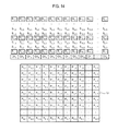
- the receiving section 330 may be configured to set a reception beam-forming curve CV 6,4 for selecting pixels that the sampling data S 6,4 are used as the pixel data thereof during the reception beam-forming based on the positions of the elements 311 and the orientation of the respective pixels of the ultrasound image UI with respect to the elements 311 , as shown in FIG. 11 .
- the receiving section 330 may be further configured to detect the pixels P 2,1 , P 3,1 , P 3,2 , P 4,2 , P 4,3 , P 4,4 , P 5,4 , P 5,5 , P 5,6 , P 5,7 , P 5,8 , P 4,9 , P 5,9 , . . .
- the receiving section 330 may select the pixels P 2,1 , P 3,1 , P 3,2 , P 4,2 , P 4,3 , P 4,4 , P 5,4 , P 5,5 , P 5,6 , P 5,7 , P 5,8 , P 4,9 , P 5,9 , . . . P 4,N , P 3,N on which the reception beam-forming curve CV 6,4 passes among the pixels P a,b of the ultrasound image UI.
- the receiving section 330 may be also configured to assign the sampling data S 6,4 to the selected pixels P 2,1 , P 3,1 , P 3,2 , P 4,2 , P 4,3 , P 4,4 , P 5,4 , P 5,5 , P 5,6 , P 5,7 , P 5,8 , P 4,9 , P 5,9 , . . . P 4,N , P 3,N , as shown in FIG. 12 .
- the respective sampling data which are used as the pixel data, may be cumulatively assigned to the pixels as the pixel data.
- the receiving section 330 may be configured to perform the reception beam-forming (i.e., summing) upon the sampling data which are cumulatively assigned to the respective pixels P a,b of the ultrasound image UI to form the reception-focused data.
- the receiving section 330 may be configured to perform the analog-digital conversion upon the reception signals provided through the plurality of channels CH k from the ultrasound probe 310 to form the sampling data S i,j , as shown in FIG. 8 .
- the sampling data S i,j may be stored in the storage unit 140 .
- the receiving section 330 may be further configured to detect pixels corresponding to the sampling data based on the positions of the elements 311 and the orientation of the pixels of the ultrasound image UI with respect to the elements 311 . That is, the receiving section 330 may select the pixels that the respective sampling data are used as the pixel data thereof during the reception beam-forming based on the positions of the elements 311 and the orientation of the respective pixels of the ultrasound image UI with respect to the elements 311 .
- the receiving section 330 may be configured to cumulatively assign the sampling data corresponding to the selected pixels as the pixel data.
- the receiving section 330 may be further configured to determine pixels existing in the same column among the selected pixels.
- the receiving section 330 may be also configured to set weights corresponding to the respective determined pixels.
- the receiving section 330 may be further configured to apply the weights to the sampling data of the respective pixels.
- the receiving section 330 may be configured to set the reception beam-forming curve CV 6,3 for selecting pixels that the sampling data S 6,3 are used as the pixel data thereof during the reception beam-forming based on the positions of the elements 311 and the orientation of the respective pixels of the ultrasound image UI with respect to the elements 311 , as shown in FIG. 9 .
- the receiving section 330 may be further configured to detect the pixels P 3,1 , P 3,2 , P 4,2 , P 4,3 , P 4,4 , P 4,5 , P 4,6 , P 4,7 , P 4,8 , P 4,9 , . . . P 3,N corresponding to the reception beam-forming curve CV 6,3 from the pixels P a,b of the ultrasound image UI.
- the receiving section 330 may select the pixels P 3,1 , P 3,2 , P 4,2 , P 4,3 , P 4,4 , P 4,5 , P 4,6 , P 4,7 , P 4,8 , P 4,9 , . . . P 3,N on which the reception beam-forming curve CV 6,3 passes among the pixels P a,b of the ultrasound image UI.
- the receiving section 330 may be further configured to assign the sampling data S 6,3 to the selected pixels P 3,1 , P 3,2 , P 4,2 , P 4,3 , P 4,4 , P 4,5 , P 4,6 , P 4,7 , P 4,8 , P 4,9 , . . . P 3,N , as shown in FIG. 10 .
- the receiving section 330 may be further configured to determine pixels P 3,2 and P 4,2 which exist in the same column among the selected pixels P 3,1 , P 3,2 , P 4,2 , P 4,3 , P 4,4 , P 4,5 , P 4,6 , P 4,7 , P 4,8 , P 4,9 , P 3,N .
- the receiving section 330 may be further configured to calculate a distance W 1 from a center of the determined pixel P 3,2 to the reception beam-forming curve CV 6,3 and a distance W 2 from a center of the determined pixel P 4,2 to the reception beam-forming curve CV 6,3 , as shown in FIG. 13 .
- the receiving section 330 may be also configured to set a first weight ⁇ 1 corresponding to the pixel P 3,2 based on the distance W 1 and a second weight ⁇ 2 corresponding to the pixel P 4,2 based on the distance W 2 .
- the first weight ⁇ 1 and the second weight ⁇ 2 may be set to be in proportion to or in inverse proportion to the calculated distances.
- the receiving section 330 may be further configured to apply the first weight ⁇ 1 to the sampling data S 6,3 assigned to the pixel P 3,2 and to apply the second weight ⁇ 2 to the sampling data S 6,3 assigned to the pixel P 4.2 .
- the receiving section 330 may be configured to perform the above process upon the remaining sampling data.
- the receiving section 330 may be configured to perform the reception beam-forming upon the sampling data which are cumulatively assigned to the respective pixels P a,b of the ultrasound image UI to form the reception-focused data.
- the receiving section 330 may be configured to perform the analog-digital conversion upon the reception signals provided through the plurality of channels CH k from the ultrasound probe 310 to form the sampling data S i,j , as shown in FIG. 8 .
- the sampling data S i,j may be stored in the storage unit 140 .
- the receiving section 330 may be further configured to set a sampling data set for selecting pixels that the sampling data S i,j are used as the pixel data thereof during the reception beam-forming.
- the receiving section 330 may be configured to set the sampling data S 1,1 , S 1,4 , . . . S 1,t , S 2,1 , S 2,4 , . . . S 2,t , . . . S p,t as the sampling data set (denoted by a box) for selecting the pixels that the sampling data S i,j are used as the pixel data thereof during the reception beam-forming, as shown in FIG. 14 .
- the receiving section 330 may be further configured to detect the pixels corresponding to the respective sampling data of the sampling data set based on the positions of the elements 311 and the orientation of the respective pixels of the ultrasound image UI with respect to the elements 311 . That is, the receiving section 330 may select the pixels that the respective sampling data of the sampling data set are used as the pixel data thereof during the reception beam-forming based on the positions of the elements 311 and the orientation of the respective pixels of the ultrasound image UI with respect to the elements 311 .
- the receiving section 330 may be further configured to cumulatively assign the sampling data to the selected pixels in the same manner as the above embodiments.
- the receiving section 330 may be further configured to perform the reception beam-forming upon the sampling data, which are cumulatively assigned to the respective pixels of the ultrasound image UI to form the reception-focused data.
- the receiving section 330 may be configured to perform a down-sampling upon the reception signals provided through the plurality of channels CH k from the ultrasound probe 310 to form down-sampling data. As described above, the receiving section 330 may be further configured to detect the pixels corresponding to the respective sampling data based on the positions of the elements 311 and the orientation of the respective pixels of the ultrasound image UI with respect to the elements 311 . That is, the receiving section 330 may select the pixels that the respective sampling data are used as the pixel data thereof during the reception beam-forming based on the positions of the elements 311 and the orientation of the pixels of the ultrasound image UI with respect to the elements 311 .
- the receiving section 330 may be further configured to cumulatively assign the respective sampling data to the selected pixels in the same manner as the above embodiments.
- the receiving section 330 may be further configured to perform the reception beam-forming upon the sampling data, which are cumulatively assigned to the respective pixels of the ultrasound image UI to form the reception-focused data.
- reception beam-forming may not be limited thereto.
- the ultrasound data acquiring unit 120 may further include an ultrasound data forming section 340 .
- the ultrasound data forming section 340 may be configured to form the ultrasound data corresponding to the ultrasound image based on the reception-focused data provided from the receiving section 330 .
- the ultrasound data forming section 340 may be further configured to perform a signal process (e.g., gain control, etc.) upon the reception-focused data.
- a signal process e.g., gain control, etc.
- the ultrasound data forming section 340 may be configured to form ultrasound data (hereinafter, referred to as “brightness mode ultrasound data”) corresponding to the brightness mode image based on the brightness mode reception-focused data provided from the receiving section 330 .
- the brightness mode ultrasound data may include radio frequency data.
- the ultrasound data forming section 340 may be further configured to form ultrasound data (hereinafter, referred to as “Doppler mode ultrasound data”) corresponding to the region of interest ROI based on the Doppler mode reception-focused data provided from the receiving section 330 .
- Doppler mode ultrasound data may include in-phase/quadrature data. However, it should be noted herein that the Doppler mode ultrasound data may not be limited thereto.
- the ultrasound data forming section 340 may form first Doppler mode ultrasound data based on the first Doppler mode reception-focused data provided from the receiving section 330 .
- the ultrasound data forming section 340 may further form second Doppler mode ultrasound data based on the second Doppler mode reception-focused data provided from the receiving section 330 .
- the ultrasound system 100 may further include a processing unit 130 in communication with the user input unit 110 and the ultrasound data acquiring unit 120 .
- the processing unit 130 may include a central processing unit, a microprocessor, a graphic processing unit and the like.
- FIG. 15 is a flow chart showing a process of forming the motion mode image.
- the processing unit 130 may be configured to form the brightness mode image BI based on the brightness mode ultrasound data provided from the ultrasound data acquiring unit 120 , at step S 1502 in FIG. 15 .
- the brightness mode image BI may be displayed on a display unit 150 .
- the processing unit 130 may be configured to set the first region of interest ROI on the brightness mode image BI based on the input information (i.e., first input information) provided from the user input unit 110 , at step S 1504 in FIG. 15 .
- the ultrasound data acquiring unit 120 may be configured to transmit the ultrasound signals to the living body and receive the ultrasound echo signals from the living body to acquire the Doppler mode ultrasound data in consideration of the first region of interest ROI.
- the processing unit 130 may be configured to form the vector information based on the Doppler mode ultrasound data provided from the ultrasound data acquiring unit 120 , at step S 1506 in FIG. 15 . That is, the processing unit 130 may form the vector information corresponding to motion (i.e., velocity and direction) of the target object based on the Doppler mode ultrasound data.
- Equation 1 X represents a reflector velocity (i.e., velocity of a target object), C 0 represents a sound speed in the living body, f d represents a Doppler shift frequency, and f 0 represents an ultrasound frequency.
- the Doppler shift frequency f d may be calculated by the difference between a frequency of the ultrasound signals (i.e., transmission beam) and a frequency of the ultrasound echo signals (i.e., reception beam). Also, the velocity component X cos ⁇ projected to the transmission direction may be calculated by Equation 1.
- the transmission direction of the ultrasound signals i.e., transmission beam
- reception direction of the ultrasound echo signals i.e., reception beam
- ⁇ R represents an angle between the ultrasound echo signals (i.e., reception beam) and the blood flow.
- FIG. 16 is a schematic diagram showing an example of the transmission directions, the reception directions, the vector information and an over-determined problem.
- the ultrasound signals i.e., transmission beam
- the ultrasound echo signals i.e., reception beam
- the ultrasound signals i.e., transmission beam
- the ultrasound echo signals i.e., reception beam
- At least two equations may be obtained and represented as the over-determined problem, as shown in FIG. 16 .
- the over-determined problem may be solved by a pseudo inverse method, a weighted least square method and the like based on noise characteristics added to the Doppler shift frequency.
- the over-determined problem is well known in the art. Thus, it has not been described in detail so as not to unnecessarily obscure the present disclosure.
- M ⁇ N equations may be obtained by M transmission directions and the reception beam-forming of N reception directions at every transmission.
- the processing unit 130 may be configured to set the second region of interest VML on the brightness mode image BI based on the input information (i.e., second input information) provided from the user input unit 110 , at step S 1508 in FIG. 15 .
- the processing unit 130 may be configured to extract brightness mode ultrasound data and vector information corresponding to the second region of interest VML from the brightness mode ultrasound data and the vector information, at step S 1510 in FIG. 15 .
- the processing unit 130 may be configured to form the motion mode image based on the extracted brightness mode ultrasound data and vector information, at step S 1512 in FIG. 15 .
- the processing unit 130 may form a brightness motion mode image based on the extracted brightness mode ultrasound data, as shown in FIG. 17 .
- the methods of forming the brightness motion mode image are well known in the art. Thus, they have not been described in detail so as not to unnecessarily obscure the present disclosure.
- the processing unit 130 may further form a color motion mode image VI 1 for representing the velocity and the direction of the target object as colors based on the extracted vector information, as shown in FIG. 17 .
- the methods of forming the color motion mode image are well known in the art. Thus, they have not been described in detail so as not to unnecessarily obscure the present disclosure.
- the processing unit 130 may further form the motion mode image based on at least one of the brightness motion mode image and the color motion mode image. That is, the processing unit 130 may form the motion mode image including the at least one of the brightness motion mode image and the color motion mode image.
- the processing unit 130 may form the brightness motion mode image based on the extracted brightness mode ultrasound data, as shown in FIG. 18 .
- the processing unit 130 may further form the color motion mode image VI 2 for representing the velocity and the direction of the target object as color vectors based on the extracted vector information, as shown in FIG. 18 .
- the processing unit 130 may further form the motion mode image based on at least one of the brightness motion mode image and the color motion mode image. That is, the processing unit 130 may form the motion mode image including the at least one of the brightness motion mode image and the color motion mode image.
- the processing unit 130 may be configured to form a Doppler mode image based on the vector information.
- the Doppler mode image may include a vector Doppler image or a color Doppler image.
- the Doppler mode image may not be limited thereto.
- the ultrasound system 100 may further include the storage unit 140 .
- the storage unit 140 may store the ultrasound data (i.e., brightness mode ultrasound data and Doppler mode ultrasound data) acquired by the ultrasound data acquiring unit 120 .
- the storage unit 140 may further store the vector information formed by the processing unit 130 .
- the ultrasound system 100 may further include the display unit 150 .
- the display unit 150 may be configured to display the brightness mode image formed by the processing unit 130 .
- the display unit 150 may be further configured to display the motion mode image formed by the processing unit 130 .
Abstract
Description
{right arrow over (α1)}{right arrow over (X)}=α 11 x 1+α12 x 2 =y 1 =X cos θ (3)
(α21+α31)x 1+(α22+α32)x 2=(y 2 +y 3)=X cos θ2 +X cos θ3 (4)
α11 x 1+α12 x 2+α13 x 3 =y (5)
(α31+α21)x 1+(α32+α22)x 2=(y 3 +y 2)
(α31+α41)x 1+(α32+α42)x 2=(y 3 +y 4) (6)
Claims (10)
Applications Claiming Priority (2)
| Application Number | Priority Date | Filing Date | Title |
|---|---|---|---|
| KR10-2011-0143854 | 2011-12-27 | ||
| KR1020110143854A KR101386099B1 (en) | 2011-12-27 | 2011-12-27 | Ultrasound system and method for providing vector motion mode image |
Publications (2)
| Publication Number | Publication Date |
|---|---|
| US20130165783A1 US20130165783A1 (en) | 2013-06-27 |
| US9232932B2 true US9232932B2 (en) | 2016-01-12 |
Family
ID=47221918
Family Applications (1)
| Application Number | Title | Priority Date | Filing Date |
|---|---|---|---|
| US13/620,619 Active 2032-09-21 US9232932B2 (en) | 2011-12-27 | 2012-09-14 | Providing motion mode image in ultrasound system |
Country Status (3)
| Country | Link |
|---|---|
| US (1) | US9232932B2 (en) |
| EP (1) | EP2609866B1 (en) |
| KR (1) | KR101386099B1 (en) |
Cited By (2)
| Publication number | Priority date | Publication date | Assignee | Title |
|---|---|---|---|---|
| US20150245821A1 (en) * | 2014-02-28 | 2015-09-03 | Samsung Medison Co., Ltd. | Ultrasound imaging apparatus and method of controlling ultrasound imaging apparatus |
| US11497465B2 (en) | 2019-10-25 | 2022-11-15 | Bard Peripheral Vascular, Inc. | Method for treatment of a vascular lesion |
Families Citing this family (5)
| Publication number | Priority date | Publication date | Assignee | Title |
|---|---|---|---|---|
| US9877699B2 (en) | 2012-03-26 | 2018-01-30 | Teratech Corporation | Tablet ultrasound system |
| US10667790B2 (en) | 2012-03-26 | 2020-06-02 | Teratech Corporation | Tablet ultrasound system |
| CN110013273B (en) * | 2015-04-29 | 2022-07-29 | 深圳迈瑞生物医疗电子股份有限公司 | Ultrasonic blood flow imaging display method and ultrasonic imaging system |
| US10792011B2 (en) | 2015-06-23 | 2020-10-06 | Hemonitor Medical Ltd. | Systems and methods for hand-free continuous ultrasonic monitoring |
| WO2016207889A1 (en) | 2015-06-23 | 2016-12-29 | Hemonitor Medical Ltd. | Continuous ultrasonic monitoring |
Citations (10)
| Publication number | Priority date | Publication date | Assignee | Title |
|---|---|---|---|---|
| JPH05146438A (en) | 1991-03-04 | 1993-06-15 | Hitachi Ltd | Ultrasonic device and vector doppler method using its device |
| JPH0775636A (en) | 1993-09-09 | 1995-03-20 | Fujitsu Ltd | Ultrasonic diagnostic device |
| JPH08622A (en) | 1994-06-17 | 1996-01-09 | Siemens Medical Syst Inc | Blood flow speed distribution display method for blood in blood vessel using ultrasonic wave picture formation device |
| US6023977A (en) * | 1997-08-01 | 2000-02-15 | Acuson Corporation | Ultrasonic imaging aberration correction system and method |
| JP2006055493A (en) | 2004-08-23 | 2006-03-02 | Toshiba Corp | Ultrasonic diagnostic equipment and medical image analyzer |
| US20060122505A1 (en) * | 2004-11-23 | 2006-06-08 | Ep Medsystems, Inc. | M-Mode presentation of an ultrasound scan |
| JP2009050720A (en) | 2008-11-04 | 2009-03-12 | Hitachi Medical Corp | Ultrasonic diagnostic system |
| US20100256491A1 (en) | 2009-04-07 | 2010-10-07 | Kwang Ju Lee | Ultrasound System and Method of Providing Color M Mode Image and Brightness M Mode Image |
| US20100305440A1 (en) | 2009-06-01 | 2010-12-02 | Medison Co., Ltd. | Ultrasound System And Method For Providing A Motion Vector |
| KR20100129681A (en) | 2009-06-01 | 2010-12-09 | 주식회사 메디슨 | Ultrasound system and method for providing motion vector |
-
2011
- 2011-12-27 KR KR1020110143854A patent/KR101386099B1/en active IP Right Grant
-
2012
- 2012-09-13 EP EP12184235.5A patent/EP2609866B1/en active Active
- 2012-09-14 US US13/620,619 patent/US9232932B2/en active Active
Patent Citations (12)
| Publication number | Priority date | Publication date | Assignee | Title |
|---|---|---|---|---|
| JPH05146438A (en) | 1991-03-04 | 1993-06-15 | Hitachi Ltd | Ultrasonic device and vector doppler method using its device |
| JPH0775636A (en) | 1993-09-09 | 1995-03-20 | Fujitsu Ltd | Ultrasonic diagnostic device |
| JPH08622A (en) | 1994-06-17 | 1996-01-09 | Siemens Medical Syst Inc | Blood flow speed distribution display method for blood in blood vessel using ultrasonic wave picture formation device |
| US6023977A (en) * | 1997-08-01 | 2000-02-15 | Acuson Corporation | Ultrasonic imaging aberration correction system and method |
| JP2006055493A (en) | 2004-08-23 | 2006-03-02 | Toshiba Corp | Ultrasonic diagnostic equipment and medical image analyzer |
| US20060122505A1 (en) * | 2004-11-23 | 2006-06-08 | Ep Medsystems, Inc. | M-Mode presentation of an ultrasound scan |
| JP2009050720A (en) | 2008-11-04 | 2009-03-12 | Hitachi Medical Corp | Ultrasonic diagnostic system |
| US20100256491A1 (en) | 2009-04-07 | 2010-10-07 | Kwang Ju Lee | Ultrasound System and Method of Providing Color M Mode Image and Brightness M Mode Image |
| KR20100111633A (en) | 2009-04-07 | 2010-10-15 | 주식회사 메디슨 | Ultrasound system and method for providing color m mode image and brightness m mode image |
| US20100305440A1 (en) | 2009-06-01 | 2010-12-02 | Medison Co., Ltd. | Ultrasound System And Method For Providing A Motion Vector |
| KR20100129681A (en) | 2009-06-01 | 2010-12-09 | 주식회사 메디슨 | Ultrasound system and method for providing motion vector |
| EP2264483A2 (en) | 2009-06-01 | 2010-12-22 | Medison Co., Ltd. | Ultrasound system and method for providing a motion vector |
Non-Patent Citations (6)
| Title |
|---|
| Extended European Search Report issued in European Application No. 12184235.5 dated Apr. 23, 2013. |
| Korean Office Action issued in Korean Application No. 10-2011-0143854 dated May 15, 2013. |
| Korean Office Action issued in Korean Patent Application No. 10-2011-0143854 dated Nov. 28, 2013, with English translation, 6 pgs. |
| Notice of Allowance issued in Korean Patent Application No. 10-2011-0143854 dated Jan. 28, 2014, with English translation, 4 pgs. |
| Pastorelli et al., "A Real-Time 2-D Vector Doppler System for Clinical Experimentation", IEEE Transactions on Medical Imaging, vol. 27, No. 10, Oct. 2008, pp. 1515-1524. |
| Pedersen et al., "Arterial secondary blood flow patterns visualized with vector flow ultrasound", 2011 IEEE Intl. Ultrasonics Symposium Proceedings, Oct. 18, 2011, pp. 1242-1245. |
Cited By (3)
| Publication number | Priority date | Publication date | Assignee | Title |
|---|---|---|---|---|
| US20150245821A1 (en) * | 2014-02-28 | 2015-09-03 | Samsung Medison Co., Ltd. | Ultrasound imaging apparatus and method of controlling ultrasound imaging apparatus |
| US10517572B2 (en) * | 2014-02-28 | 2019-12-31 | Samsung Medison Co., Ltd. | Ultrasound imaging apparatus and method of controlling ultrasound imaging apparatus |
| US11497465B2 (en) | 2019-10-25 | 2022-11-15 | Bard Peripheral Vascular, Inc. | Method for treatment of a vascular lesion |
Also Published As
| Publication number | Publication date |
|---|---|
| EP2609866B1 (en) | 2022-05-25 |
| US20130165783A1 (en) | 2013-06-27 |
| KR101386099B1 (en) | 2014-04-16 |
| KR20130075477A (en) | 2013-07-05 |
| EP2609866A1 (en) | 2013-07-03 |
Similar Documents
| Publication | Publication Date | Title |
|---|---|---|
| US20130172745A1 (en) | Providing vector doppler image based on decision data in ultrasound system | |
| US11406362B2 (en) | Providing user interface in ultrasound system | |
| US20130165784A1 (en) | Providing motion profile information of target object in ultrasound system | |
| US9232932B2 (en) | Providing motion mode image in ultrasound system | |
| US9474510B2 (en) | Ultrasound and system for forming an ultrasound image | |
| US20130172755A1 (en) | Providing turbulent flow information based on vector doppler in ultrasound system | |
| US20130172749A1 (en) | Providing doppler spectrum images corresponding to at least two sample volumes in ultrasound system | |
| US20130172747A1 (en) | Estimating motion of particle based on vector doppler in ultrasound system | |
| US20130165792A1 (en) | Forming vector information based on vector doppler in ultrasound system | |
| US9510803B2 (en) | Providing compound image of doppler spectrum images in ultrasound system | |
| US20130172744A1 (en) | Providing particle flow image in ultrasound system | |
| US9474503B2 (en) | Ultrasound system and method for detecting vector information using transmission delays | |
| US20120078108A1 (en) | Providing additional information corresponding to change of blood flow with a time in ultrasound system | |
| US20130165793A1 (en) | Providing doppler information of target object based on vector doppler in ultrasound system | |
| KR101511502B1 (en) | Ultrasound system and method for dectecting vecotr information based on transmitting delay |
Legal Events
| Date | Code | Title | Description |
|---|---|---|---|
| AS | Assignment |
Owner name: SAMSUNG MEDISON CO., LTD., KOREA, REPUBLIC OF Free format text: ASSIGNMENT OF ASSIGNORS INTEREST;ASSIGNORS:KIM, MIN WOO;KANG, WOO HYUN;REEL/FRAME:028970/0356 Effective date: 20120912 |
|
| FEPP | Fee payment procedure |
Free format text: PAYOR NUMBER ASSIGNED (ORIGINAL EVENT CODE: ASPN); ENTITY STATUS OF PATENT OWNER: LARGE ENTITY |
|
| STCF | Information on status: patent grant |
Free format text: PATENTED CASE |
|
| MAFP | Maintenance fee payment |
Free format text: PAYMENT OF MAINTENANCE FEE, 4TH YEAR, LARGE ENTITY (ORIGINAL EVENT CODE: M1551); ENTITY STATUS OF PATENT OWNER: LARGE ENTITY Year of fee payment: 4 |
|
| MAFP | Maintenance fee payment |
Free format text: PAYMENT OF MAINTENANCE FEE, 8TH YEAR, LARGE ENTITY (ORIGINAL EVENT CODE: M1552); ENTITY STATUS OF PATENT OWNER: LARGE ENTITY Year of fee payment: 8 |