EP2264483A2 - Ultrasound system and method for providing a motion vector - Google Patents
Ultrasound system and method for providing a motion vector Download PDFInfo
- Publication number
- EP2264483A2 EP2264483A2 EP10163199A EP10163199A EP2264483A2 EP 2264483 A2 EP2264483 A2 EP 2264483A2 EP 10163199 A EP10163199 A EP 10163199A EP 10163199 A EP10163199 A EP 10163199A EP 2264483 A2 EP2264483 A2 EP 2264483A2
- Authority
- EP
- European Patent Office
- Prior art keywords
- motion vector
- ultrasound data
- edge
- angle
- image
- Prior art date
- Legal status (The legal status is an assumption and is not a legal conclusion. Google has not performed a legal analysis and makes no representation as to the accuracy of the status listed.)
- Granted
Links
Images


Classifications
-
- G—PHYSICS
- G06—COMPUTING OR CALCULATING; COUNTING
- G06T—IMAGE DATA PROCESSING OR GENERATION, IN GENERAL
- G06T7/00—Image analysis
- G06T7/20—Analysis of motion
-
- G—PHYSICS
- G01—MEASURING; TESTING
- G01S—RADIO DIRECTION-FINDING; RADIO NAVIGATION; DETERMINING DISTANCE OR VELOCITY BY USE OF RADIO WAVES; LOCATING OR PRESENCE-DETECTING BY USE OF THE REFLECTION OR RERADIATION OF RADIO WAVES; ANALOGOUS ARRANGEMENTS USING OTHER WAVES
- G01S15/00—Systems using the reflection or reradiation of acoustic waves, e.g. sonar systems
- G01S15/88—Sonar systems specially adapted for specific applications
- G01S15/89—Sonar systems specially adapted for specific applications for mapping or imaging
- G01S15/8906—Short-range imaging systems; Acoustic microscope systems using pulse-echo techniques
- G01S15/8979—Combined Doppler and pulse-echo imaging systems
- G01S15/8984—Measuring the velocity vector
-
- G—PHYSICS
- G01—MEASURING; TESTING
- G01S—RADIO DIRECTION-FINDING; RADIO NAVIGATION; DETERMINING DISTANCE OR VELOCITY BY USE OF RADIO WAVES; LOCATING OR PRESENCE-DETECTING BY USE OF THE REFLECTION OR RERADIATION OF RADIO WAVES; ANALOGOUS ARRANGEMENTS USING OTHER WAVES
- G01S7/00—Details of systems according to groups G01S13/00, G01S15/00, G01S17/00
- G01S7/52—Details of systems according to groups G01S13/00, G01S15/00, G01S17/00 of systems according to group G01S15/00
- G01S7/52017—Details of systems according to groups G01S13/00, G01S15/00, G01S17/00 of systems according to group G01S15/00 particularly adapted to short-range imaging
- G01S7/52053—Display arrangements
- G01S7/52057—Cathode ray tube displays
- G01S7/52071—Multicolour displays; using colour coding; Optimising colour or information content in displays, e.g. parametric imaging
-
- G—PHYSICS
- G06—COMPUTING OR CALCULATING; COUNTING
- G06T—IMAGE DATA PROCESSING OR GENERATION, IN GENERAL
- G06T2207/00—Indexing scheme for image analysis or image enhancement
- G06T2207/10—Image acquisition modality
- G06T2207/10132—Ultrasound image
Definitions
- the present disclosure relates to ultrasound systems, and more particularly to an ultrasound system and method of providing a motion vector, which comprises the speed and direction of movement of a moving object of interest.
- an ultrasound system Due to its non-invasive and non-destructive nature, an ultrasound system has been extensively used in the medical field to acquire internal information of a target object.
- the ultrasound system is used in the medical field since it can provide doctors with a high resolution image of internal tissues of the target object without the need of surgical treatment.
- the ultrasound system may function in various modes including a brightness mode (B-mode) wherein reflection coefficients of the ultrasound signal reflected by the target object may be visualized, a Doppler mode (D-mode) wherein speed information of a moving target object (especially bloodstream) may be acquired by using the Doppler effect, and an elastic mode (E-mode) wherein mechanical characteristics of tissues may be visualized based on strains representing deformation of the tissues due to the application of the stress.
- B-mode brightness mode
- D-mode Doppler mode
- E-mode elastic mode
- the Doppler mode is based on a Doppler frequency, which is the difference between the frequency of the transmitted ultrasound signal from an ultrasound probe ("transmission frequency”) and the frequency of the echo signal reflected from the moving target object and received through the ultrasound probe ("reception frequency”).
- the Doppler frequency varies according to the angle ("Doppler angle") between an ultrasound beam consisting of a group of ultrasound signals and the reflecting object (i.e., bloodstream). For example, assuming that the reflecting object is moving at a speed of 1m/s and the transmission frequency is 5MHz, the reception frequency would be 6.5MHz when the Doppler angle is 0° and 0MHz when the Doppler angle is 90°.
- the speed of the bloodstream cannot be estimated if the Doppler angle is 90°.
- the bloodstream may be displayed as moving in the direction opposite to its actual direction depending on the angle of the ultrasound beam.
- an ultrasound system and method for providing a motion vector of a moving object of interest e.g., bloodstream
- a color Doppler mode image and ultrasound data comprising speed information of the object of interest.
- a method of providing a motion vector on an ultrasound image comprises: acquiring a brightness mode (B-mode) image of a target object; enabling a region of interest (ROI) to be set in the B-mode image, the ROI covering a moving object in the target object; acquiring ultrasound data for a portion of the target object corresponding to the ROI, the ultrasound data including speed information of the moving object; forming a color Doppler mode image of the portion based on the ultrasound data; forming a motion vector of the moving object based on the ultrasound data and the color Doppler mode image; and setting the motion vector on the color Doppler mode image.
- B-mode brightness mode
- ROI region of interest
- a system for providing a motion vector on an ultrasound image comprises: an image acquisition unit configured to acquire a brightness mode (B-mode) image of a target object; a region setting unit configured to enable a region of interest (ROI) to be set in the B-mode image, the ROI covering a moving object in the target object; an ultrasound data acquisition unit configured to acquire ultrasound data for a portion of the target object corresponding to the ROI, the ultrasound data including speed information of the moving object; an image forming unit configured to form a color Doppler mode image of the portion based on the ultrasound data; a processor configured to form a motion vector of the moving object based on the ultrasound data and the color Doppler mode image and to set the motion vector on the color Doppler mode image.
- B-mode brightness mode
- ROI region of interest
- the ultrasound system and method according to the present disclosure can provide a motion vector comprising a speed and direction of movement of a moving object of interest (e.g., bloodstream) without lowering the frame rate.
- a moving object of interest e.g., bloodstream
- it can accurately provide a user with the direction of movement of the moving object of interest.
- Doppler mode comprises a color Doppler mode
- a target object comprises a moving object of interest (e.g., bloodstream).
- FIG. 1 illustrates a block diagram showing an arrangement of an ultrasound system 100 according to an embodiment of the present disclosure.
- the ultrasound system 100 may comprise an ultrasound data acquisition unit 110, an image forming unit 120, a processor 130, a display unit 140 and a control unit 150.
- the ultrasound system 100 may further comprise a user input unit (not shown), which is configured to receive from a user setting information on a region of interest (ROI) (i.e., color box) for acquiring a Doppler mode image of the object of interest.
- ROI region of interest
- the user input unit may comprise a control panel, a mouse, a keyboard and the like.
- the setting information of the region of interest may include the size and location of the region of interest within a brightness mode (B-mode) image.
- B-mode brightness mode
- the ultrasound data acquisition unit 110 may transmit an ultrasound signal to a target object and receive the ultrasound signal reflected by the target object (i.e., ultrasound echo signal), thereby acquiring ultrasound data corresponding to scanlines of the region of interest within the B-mode image.
- FIG. 2 illustrates a block diagram showing an arrangement of the ultrasound data acquisition unit 110 according to an embodiment of the present disclosure.
- the ultrasound data acquisition unit 110 may comprise a transmission signal forming unit 111, an ultrasound probe 112 including multiple transducer elements, a beam former 113 and an ultrasound data forming unit 114.
- the transmission signal forming unit 111 may form transmission signals, which will be applied to the ultrasound probe 112 for acquiring a Doppler mode image in consideration of the focal points and locations of the transducer elements of the ultrasound probe 112.
- the ultrasound probe 112 may convert the transmission signals provided from the transmission signal forming unit 111 into ultrasound signals, transmit the ultrasound signals to the target object, and receive the ultrasound echo signals reflected by the target object to thereby form reception signals.
- the ultrasound probe 112 may comprise multiple transducer elements 112a configured to perform inter-conversion between an ultrasound signal and an electrical signal, as shown in Figure 3 .
- a group of ultrasound signals transmitted from the multiple transducer elements 112a are formed into ultrasound beams, and then transmitted to the target object along the respective multiple scanlines, as shown in Figure 3.
- Figure 3 shows the lateral direction perpendicular to the axial direction and the elevation direction which is the thickness direction in cross section of the target object.
- the beam former 113 may perform analog-to-digital conversion of the reception signals provided by the ultrasound probe 112.
- the beam former 113 may form receive-focused signals by receive-focusing the digital-converted reception signals in consideration of the focal points and locations of the transducer elements of the ultrasound probe 112.
- the ultrasound data forming unit 114 may form ultrasound data corresponding to each of the multiple scanlines using the receive-focused signals provided by the beam former 113.
- the ultrasound data may comprise speed information of the object of interest.
- the ultrasound data forming unit 114 may further perform multiple signal processing (e.g., gain control, filtering, etc.) to form a Doppler mode image.
- the image forming unit 120 may form a Doppler mode image 220, in which the speed of the object of interest (e.g., bloodstream) approaching the ultrasound probe 112 and the speed of the object of interest receding from the ultrasound probe 112 are represented in different colors, as shown in Figure 5 .
- reference numerals 210, 221 and 222 represent the B-mode image, the region of interest and the blood vessel, respectively.
- the processor 130 may set a motion vector, which comprises the speed and direction of movement of the object of interest, by using the ultrasound data provided by the ultrasound data acquisition unit 110 and the Doppler mode image provided by the image forming unit 120.
- FIG. 4 illustrates a block diagram showing an arrangement of a processor 130 according to an embodiment of the present disclosure.
- the processor 130 may comprise an edge detection unit 131, a line setting unit 132, an intersection detection unit 133, an area setting unit 134, an angle calculation unit 135 and a motion vector setting unit 136.
- the edge detection unit 131 may detect an edge (i.e., blood vessel 222) by analyzing the Doppler mode image 220 provided by the image forming unit 120.
- the edge may be detected based on the brightness changes and using differential operators.
- the edge may be detected by using an edge mask such as Sobel, Prewitt, Robert, Canny mask, etc.
- the edge may be detected based on the differences between eigenvalues and using structure tensors.
- the line setting unit 132 may set lines perpendicular to the edge (i.e., blood vessel) detected by the edge detection unit 131.
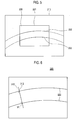
- the line setting unit 132 may set a line 310, which is perpendicular to the edge (i.e., blood vessel 222), as described in Figure 6 .
- the intersection detection unit 133 may detect first and second intersections 311 and 312, each of which is the intersection of the edge (i.e., blood vessel 222) and the line set by the line setting unit 132.
- the area setting unit 134 may set first areas including pre-defined number of pixels, wherein each of the first areas is centered at the intersections detected by the intersection detection unit 133.
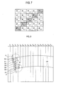
- the area setting unit 134 may set a first area, which includes 5x5 pixels and is centered at the first intersection P 3, 3 311 as described in Figure 7 .
- shaded pixels P 1, 5 , P 2, 4 , P 3, 3 , P 4, 2 , P 5, 1 represent the edge.
- the area setting unit 134 may also set a first area for the second intersection 312, which includes 5x5 pixels and is centered at the second intersection 312 as described above.
- the angle calculation unit 135 may detect pixels corresponding to the edge for each of the first and second intersections 311 and 312, and calculate angles of edges at each of the first and second intersections 311 and 312 by using the detected pixels.
- the angle calculation unit 135 may detect pixels P 1, 5 , P 2, 4 , P 3, 3 , P 4, 2 , P 5, 1 corresponding to the edge for the first intersection 311 within the area including 5x5 pixels, as shown in Figure 7 .
- the angle calculation unit 135 may calculate the angle ⁇ of the edge at the first intersection 311 by using the left-most pixel P 5 , 1 and the rightmost pixel P 1, 5 among the detected pixels, as shown in Figure 9a .
- the methods of calculating the angle of the edge are well known in the art. Thus, they have not been described in detail so as not to unnecessarily obscure the present disclosure.
- the angle calculation unit 135 may also calculate the angle ⁇ ' for the second intersection 312, as shown in Figure 9b .
- the motion vector setting unit 136 may form a motion vector, which includes a speed and direction of movement of the object of interest, by using ultrasound data provided by the ultrasound data acquisition unit 110 and the angle calculated by the angle calculation unit 135. The motion vector setting unit 136 may then set the motion vector on the Doppler mode image.
- the motion vector setting unit 136 may set a plurality of second areas 321-325 on the line segment demarcated by the first intersection 311 and the second intersection 312 on the line 310, as shown in Figure 8 .
- Each of the second areas 321-325 may have a predetermined size (e.g., 5x5), and the center of each of the second areas 321-325 may be located on the line 310.
- the second areas 321-325 may be set in an overlapping manner.
- the motion vector setting unit 136 may obtain object-of-interest information corresponding to each of the second areas 321-325 by using the ultrasound data for the scanline corresponding to the respective second area.
- the object-of-interest information comprises the size (speed) and direction of movement of the moving object of interest (e.g., bloodstream).
- the motion vector setting unit 136 may obtain object-of-interest information by using the ultrasound data for the scanline most adjacent the respective second area.
- the motion vector setting unit 136 may calculate an average speed in each of the second areas 321-325 by using the respectively obtained object-of-interest information.
- the motion vector setting unit 136 may form motion vectors V 1 -V 5 for the second areas 321-325 based on the calculated average speeds and the angle of the edge calculated by the angle calculation unit 135, and may set the formed motion vectors V 1 -V 5 on the Doppler mode image 220.
- the display unit 140 may display the Doppler mode image 220 and the motion vectors V 1 -V 5 .
- the control unit 150 may control the transmission and receiving of the ultrasound signals, and control the formation of the ultrasound data.
- the control unit 150 may also control the formation and display of the Doppler mode image, and control the formation and display of the vectors.
Landscapes
- Engineering & Computer Science (AREA)
- Physics & Mathematics (AREA)
- Radar, Positioning & Navigation (AREA)
- Remote Sensing (AREA)
- Acoustics & Sound (AREA)
- General Physics & Mathematics (AREA)
- Computer Networks & Wireless Communication (AREA)
- Multimedia (AREA)
- Computer Vision & Pattern Recognition (AREA)
- Theoretical Computer Science (AREA)
- Ultra Sonic Daignosis Equipment (AREA)
Abstract
Description
- The present application claims priority from Korean Patent Application Nos. 10-2009-
0048206 (filed on June 1, 2009 10-2010-0042290 (filed on May 6, 2010 - The present disclosure relates to ultrasound systems, and more particularly to an ultrasound system and method of providing a motion vector, which comprises the speed and direction of movement of a moving object of interest.
- Due to its non-invasive and non-destructive nature, an ultrasound system has been extensively used in the medical field to acquire internal information of a target object. The ultrasound system is used in the medical field since it can provide doctors with a high resolution image of internal tissues of the target object without the need of surgical treatment.
- As is known in the art, the ultrasound system may function in various modes including a brightness mode (B-mode) wherein reflection coefficients of the ultrasound signal reflected by the target object may be visualized, a Doppler mode (D-mode) wherein speed information of a moving target object (especially bloodstream) may be acquired by using the Doppler effect, and an elastic mode (E-mode) wherein mechanical characteristics of tissues may be visualized based on strains representing deformation of the tissues due to the application of the stress.
- The Doppler mode is based on a Doppler frequency, which is the difference between the frequency of the transmitted ultrasound signal from an ultrasound probe ("transmission frequency") and the frequency of the echo signal reflected from the moving target object and received through the ultrasound probe ("reception frequency"). The Doppler frequency varies according to the angle ("Doppler angle") between an ultrasound beam consisting of a group of ultrasound signals and the reflecting object (i.e., bloodstream). For example, assuming that the reflecting object is moving at a speed of 1m/s and the transmission frequency is 5MHz, the reception frequency would be 6.5MHz when the Doppler angle is 0° and 0MHz when the Doppler angle is 90°.
- As such, the speed of the bloodstream cannot be estimated if the Doppler angle is 90°. Further, for a convex probe, the bloodstream may be displayed as moving in the direction opposite to its actual direction depending on the angle of the ultrasound beam.
- To solve the above problems, a method of using two ultrasound beams or speckle information has been proposed to detect the speed of the bloodstream having the Doppler angle of 90°. However, such a method is not practical since the performance is not stable or the frame rate is too low to allow for real time display.
- According to the present disclosure, there is disclosed an ultrasound system and method for providing a motion vector of a moving object of interest (e.g., bloodstream) by using a color Doppler mode image and ultrasound data comprising speed information of the object of interest.
- According to an aspect of the present disclosure, a method of providing a motion vector on an ultrasound image comprises: acquiring a brightness mode (B-mode) image of a target object; enabling a region of interest (ROI) to be set in the B-mode image, the ROI covering a moving object in the target object; acquiring ultrasound data for a portion of the target object corresponding to the ROI, the ultrasound data including speed information of the moving object; forming a color Doppler mode image of the portion based on the ultrasound data; forming a motion vector of the moving object based on the ultrasound data and the color Doppler mode image; and setting the motion vector on the color Doppler mode image.
- According to another aspect of the present disclosure, a system for providing a motion vector on an ultrasound image comprises: an image acquisition unit configured to acquire a brightness mode (B-mode) image of a target object; a region setting unit configured to enable a region of interest (ROI) to be set in the B-mode image, the ROI covering a moving object in the target object; an ultrasound data acquisition unit configured to acquire ultrasound data for a portion of the target object corresponding to the ROI, the ultrasound data including speed information of the moving object; an image forming unit configured to form a color Doppler mode image of the portion based on the ultrasound data; a processor configured to form a motion vector of the moving object based on the ultrasound data and the color Doppler mode image and to set the motion vector on the color Doppler mode image.
- The ultrasound system and method according to the present disclosure can provide a motion vector comprising a speed and direction of movement of a moving object of interest (e.g., bloodstream) without lowering the frame rate. Thus, it can accurately provide a user with the direction of movement of the moving object of interest.
-
-
Figure 1 illustrates a block diagram showing an arrangement of an ultrasound system according to an embodiment of the present disclosure. -
Figure 2 illustrates a block diagram showing an arrangement of an ultrasound data acquisition unit according to an embodiment of the present disclosure. -
Figure 3 illustrates a schematic diagram showing transducer elements, scanlines and coordinate system according to an embodiment of the present disclosure. -
Figure 4 illustrates a block diagram showing an arrangement of a processor according to an embodiment of the present disclosure. -
Figure 5 illustrates a diagram showing a B-mode image, a Doppler mode image, a region of interest and a bloodstream according to an embodiment of the present disclosure. -
Figure 6 illustrates a diagram showing lines and intersects according to an embodiment of the present disclosure. -
Figure 7 illustrates a diagram showing an area including 5x5 pixels according to an embodiment of the present disclosure. -
Figure 8 illustrates a diagram showing a motion vector formed according to an embodiment of the present disclosure. -
Figure 9a illustrates an enlarged view of portion A shown inFigure 8 . -
Figure 9b illustrates an enlarged view of portion B shown inFigure 8 . - Embodiments of the present disclosure are described below with reference to the accompanying drawings. As used herein, the term "Doppler mode" comprises a color Doppler mode, while a target object comprises a moving object of interest (e.g., bloodstream).
-
Figure 1 illustrates a block diagram showing an arrangement of an ultrasound system 100 according to an embodiment of the present disclosure. The ultrasound system 100 may comprise an ultrasounddata acquisition unit 110, animage forming unit 120, aprocessor 130, adisplay unit 140 and acontrol unit 150. The ultrasound system 100 may further comprise a user input unit (not shown), which is configured to receive from a user setting information on a region of interest (ROI) (i.e., color box) for acquiring a Doppler mode image of the object of interest. The user input unit may comprise a control panel, a mouse, a keyboard and the like. In this embodiment, the setting information of the region of interest may include the size and location of the region of interest within a brightness mode (B-mode) image. - The ultrasound
data acquisition unit 110 may transmit an ultrasound signal to a target object and receive the ultrasound signal reflected by the target object (i.e., ultrasound echo signal), thereby acquiring ultrasound data corresponding to scanlines of the region of interest within the B-mode image. -
Figure 2 illustrates a block diagram showing an arrangement of the ultrasounddata acquisition unit 110 according to an embodiment of the present disclosure. The ultrasounddata acquisition unit 110 may comprise a transmissionsignal forming unit 111, anultrasound probe 112 including multiple transducer elements, a beam former 113 and an ultrasounddata forming unit 114. - The transmission
signal forming unit 111 may form transmission signals, which will be applied to theultrasound probe 112 for acquiring a Doppler mode image in consideration of the focal points and locations of the transducer elements of theultrasound probe 112. - The
ultrasound probe 112 may convert the transmission signals provided from the transmissionsignal forming unit 111 into ultrasound signals, transmit the ultrasound signals to the target object, and receive the ultrasound echo signals reflected by the target object to thereby form reception signals. Theultrasound probe 112 may comprisemultiple transducer elements 112a configured to perform inter-conversion between an ultrasound signal and an electrical signal, as shown inFigure 3 . A group of ultrasound signals transmitted from themultiple transducer elements 112a are formed into ultrasound beams, and then transmitted to the target object along the respective multiple scanlines, as shown inFigure 3. Figure 3 shows the lateral direction perpendicular to the axial direction and the elevation direction which is the thickness direction in cross section of the target object. - The beam former 113 may perform analog-to-digital conversion of the reception signals provided by the
ultrasound probe 112. The beam former 113 may form receive-focused signals by receive-focusing the digital-converted reception signals in consideration of the focal points and locations of the transducer elements of theultrasound probe 112. - The ultrasound
data forming unit 114 may form ultrasound data corresponding to each of the multiple scanlines using the receive-focused signals provided by the beam former 113. The ultrasound data may comprise speed information of the object of interest. The ultrasounddata forming unit 114 may further perform multiple signal processing (e.g., gain control, filtering, etc.) to form a Doppler mode image. - Referring back to
Figure 1 , theimage forming unit 120 may form aDoppler mode image 220, in which the speed of the object of interest (e.g., bloodstream) approaching theultrasound probe 112 and the speed of the object of interest receding from theultrasound probe 112 are represented in different colors, as shown inFigure 5 . InFigure 5 ,reference numerals - The
processor 130 may set a motion vector, which comprises the speed and direction of movement of the object of interest, by using the ultrasound data provided by the ultrasounddata acquisition unit 110 and the Doppler mode image provided by theimage forming unit 120. -
Figure 4 illustrates a block diagram showing an arrangement of aprocessor 130 according to an embodiment of the present disclosure. Theprocessor 130 may comprise anedge detection unit 131, aline setting unit 132, anintersection detection unit 133, anarea setting unit 134, anangle calculation unit 135 and a motionvector setting unit 136. - The
edge detection unit 131 may detect an edge (i.e., blood vessel 222) by analyzing theDoppler mode image 220 provided by theimage forming unit 120. The edge may be detected based on the brightness changes and using differential operators. In this embodiment, the edge may be detected by using an edge mask such as Sobel, Prewitt, Robert, Canny mask, etc. Alternatively, the edge may be detected based on the differences between eigenvalues and using structure tensors. - The
line setting unit 132 may set lines perpendicular to the edge (i.e., blood vessel) detected by theedge detection unit 131. As an example, theline setting unit 132 may set aline 310, which is perpendicular to the edge (i.e., blood vessel 222), as described inFigure 6 . - The
intersection detection unit 133 may detect first andsecond intersections line setting unit 132. - The
area setting unit 134 may set first areas including pre-defined number of pixels, wherein each of the first areas is centered at the intersections detected by theintersection detection unit 133. As an example, thearea setting unit 134 may set a first area, which includes 5x5 pixels and is centered at thefirst intersection P 3, 3 311 as described inFigure 7 . InFigure 7 , shaded pixels P1, 5, P2, 4, P3, 3, P4, 2, P5, 1 represent the edge. Thearea setting unit 134 may also set a first area for thesecond intersection 312, which includes 5x5 pixels and is centered at thesecond intersection 312 as described above. - The
angle calculation unit 135 may detect pixels corresponding to the edge for each of the first andsecond intersections second intersections angle calculation unit 135 may detect pixels P1, 5, P2, 4, P3, 3, P4, 2, P5, 1 corresponding to the edge for thefirst intersection 311 within the area including 5x5 pixels, as shown inFigure 7 . Theangle calculation unit 135 may calculate the angle θ of the edge at thefirst intersection 311 by using the left-most pixel P5, 1 and the rightmost pixel P1, 5 among the detected pixels, as shown inFigure 9a . The methods of calculating the angle of the edge are well known in the art. Thus, they have not been described in detail so as not to unnecessarily obscure the present disclosure. Similarly, theangle calculation unit 135 may also calculate the angle θ' for thesecond intersection 312, as shown inFigure 9b . - The motion
vector setting unit 136 may form a motion vector, which includes a speed and direction of movement of the object of interest, by using ultrasound data provided by the ultrasounddata acquisition unit 110 and the angle calculated by theangle calculation unit 135. The motionvector setting unit 136 may then set the motion vector on the Doppler mode image. - In particular, the motion
vector setting unit 136 may set a plurality of second areas 321-325 on the line segment demarcated by thefirst intersection 311 and thesecond intersection 312 on theline 310, as shown inFigure 8 . Each of the second areas 321-325 may have a predetermined size (e.g., 5x5), and the center of each of the second areas 321-325 may be located on theline 310. In one embodiment, the second areas 321-325 may be set in an overlapping manner. Although the foregoing embodiment has been described to set the five second areas 321-325 on theline 310, the present disclosure is not limited thereto. - In one embodiment, the motion
vector setting unit 136 may obtain object-of-interest information corresponding to each of the second areas 321-325 by using the ultrasound data for the scanline corresponding to the respective second area. The object-of-interest information comprises the size (speed) and direction of movement of the moving object of interest (e.g., bloodstream). In another embodiment, the motionvector setting unit 136 may obtain object-of-interest information by using the ultrasound data for the scanline most adjacent the respective second area. - The motion
vector setting unit 136 may calculate an average speed in each of the second areas 321-325 by using the respectively obtained object-of-interest information. The motionvector setting unit 136 may form motion vectors V1-V5 for the second areas 321-325 based on the calculated average speeds and the angle of the edge calculated by theangle calculation unit 135, and may set the formed motion vectors V1-V5 on theDoppler mode image 220. - Referring back to
Figure 1 , thedisplay unit 140 may display theDoppler mode image 220 and the motion vectors V1-V5. - The
control unit 150 may control the transmission and receiving of the ultrasound signals, and control the formation of the ultrasound data. Thecontrol unit 150 may also control the formation and display of the Doppler mode image, and control the formation and display of the vectors. - While the present disclosure is described via some preferred embodiments, it will be appreciated by those skilled persons in the art that many modifications and changes can be made without departing the spirit and scope of the appended claims.
- As an example, while only one
line 310 perpendicular to the edge (i.e., blood vessel 222) and second areas on theline 310 are used to form a motion vector of the object of interest in the foregoing embodiments, at least two different lines perpendicular to the edge (i.e., blood vessel 222) at different locations and second areas on the at least two different lines may be used to form the motion vector of the object of interest in other embodiments.
Claims (12)
- A method of providing a motion vector on an ultrasound image, comprising:acquiring a brightness mode (B-mode) image of a target object;enabling a region of interest (ROI) to be set in the B-mode image, the ROI covering a moving object in the target object;acquiring ultrasound data for a portion of the target object corresponding to the ROI, the ultrasound data including speed information of the moving object;forming a color Doppler mode image of the portion based on the ultrasound data;forming a motion vector of the moving object based on the ultrasound data and the color Doppler mode image; andsetting the motion vector on the color Doppler mode image.
- The method of Claim 1, wherein forming a motion vector comprises:detecting an edge of a blood vessel, through which the moving object flows,based on the color Doppler mode image;setting at least one line perpendicular to the edge;detecting at least one intersection of the at least one line and the edge;setting a first area including a predetermined number of pixels to be centered at the at least one intersection;detecting pixels corresponding to the edge within the first area;calculating an angle of the edge at the intersection based on the detected pixels;andforming the motion vector based on the ultrasound data and the angle.
- The method of Claim 2, wherein calculating an angle comprises calculating the angle by using a left-most pixel and a right most pixel among the detected pixels.
- The method of Claim 2, wherein forming the motion vector based on the ultrasound data and the angle comprises:setting a plurality of second areas on a line segment demarcated by the at least one intersection on the at least one line;obtaining object-of-interest information for each of the plurality of second areas based at least in part on the ultrasound data for a scanline corresponding to the respective second area;calculating an average speed in each of the plurality of second areas based on the respectively obtained object-of-interest information;forming the motion vector for each of the plurality of second areas based on the respective average speed and the angle of the edge.
- The method of Claim 4, wherein the object-of-interest information comprises a speed and direction of movement of the object of interest.
- The method of any one of Claims 1-5, further comprising displaying the color Doppler mode image with the motion vector set.
- A system of providing a motion vector on an ultrasound image, comprising:an image acquisition unit configured to acquire a brightness mode (B-mode) image of a target object;a region setting unit configured to enable a region of interest (ROI) to be set in the B-mode image, the ROI covering a moving object in the target object;an ultrasound data acquisition unit configured to acquire ultrasound data for a portion of the target object corresponding to the ROI, the ultrasound data including speed information of the moving object;an image forming unit configured to form a color Doppler mode image of the portion based on the ultrasound data;a processor configured to form a motion vector of the moving object based on the ultrasound data and the color Doppler mode image and to set the motion vector on the color Doppler mode image.
- The system of Claim 7, wherein the processor comprises:an edge detection unit configured to detect an edge of a blood vessel, through which the moving object flows, based on the color Doppler mode image;a line setting unit configured to set at least one line perpendicular to the edge;an intersection detection unit configured to detect at least one intersection of the at least one line and the edge;an area setting unit configured to set a first area including a predetermined number of pixels to be centered at the at least one intersection;an angle calculation unit configured to detect pixels corresponding to the edge within the first area and to calculate an angle of the edge at the intersection based on the detected pixels; anda motion vector setting unit configured to form the motion vector based on the ultrasound data and the angle.
- The system of Claim 8, wherein the angle calculation unit is configured to calculate the angle by using a left-most pixel and a right most pixel among the detected pixels.
- The system of Claim 8, wherein the motion vector setting unit configured to set a plurality of second areas on a line segment demarcated by the at least one intersection on the at least one line, obtain object-of-interest information for each of the plurality of second areas based at least in part on the ultrasound data for a scanline corresponding to the respective second area, calculate an average speed in each of the plurality of second areas based on the respectively obtained object-of-interest information, and form the motion vector for each of the plurality of second areas based on the respective average speed and the angle of the edge.
- The system of Claim 10, wherein the object-of-interest information comprises a speed and direction of movement of the object of interest.
- The system of any one of Claims 7-11, further comprising a display unit configured to display the color Doppler mode image with the motion vector set.
Applications Claiming Priority (2)
| Application Number | Priority Date | Filing Date | Title |
|---|---|---|---|
| KR20090048206 | 2009-06-01 | ||
| KR20100042290A KR101120812B1 (en) | 2009-06-01 | 2010-05-06 | Ultrasound system and method for providing motion vector |
Publications (3)
| Publication Number | Publication Date |
|---|---|
| EP2264483A2 true EP2264483A2 (en) | 2010-12-22 |
| EP2264483A3 EP2264483A3 (en) | 2013-05-22 |
| EP2264483B1 EP2264483B1 (en) | 2017-11-29 |
Family
ID=42352149
Family Applications (1)
| Application Number | Title | Priority Date | Filing Date |
|---|---|---|---|
| EP10163199.2A Active EP2264483B1 (en) | 2009-06-01 | 2010-05-19 | Ultrasound system and method for providing a motion vector |
Country Status (3)
| Country | Link |
|---|---|
| US (1) | US20100305440A1 (en) |
| EP (1) | EP2264483B1 (en) |
| JP (1) | JP5592164B2 (en) |
Cited By (2)
| Publication number | Priority date | Publication date | Assignee | Title |
|---|---|---|---|---|
| EP2609866A1 (en) * | 2011-12-27 | 2013-07-03 | Samsung Medison Co., Ltd. | Providing motion mode image in ultrasound system |
| CN103181790A (en) * | 2011-12-29 | 2013-07-03 | 三星麦迪森株式会社 | Providing turbulent flow information and ultrasound system |
Families Citing this family (7)
| Publication number | Priority date | Publication date | Assignee | Title |
|---|---|---|---|---|
| JP5265810B2 (en) * | 2010-10-08 | 2013-08-14 | パナソニック株式会社 | Ultrasonic diagnostic apparatus and in-vivo observation method |
| KR101406807B1 (en) | 2011-12-28 | 2014-06-12 | 삼성메디슨 주식회사 | Ultrasound system and method for providing user interface |
| KR101348771B1 (en) * | 2011-12-28 | 2014-01-07 | 삼성메디슨 주식회사 | Ultrasound system and method for estimating motion of particle based on vector doppler |
| KR102185727B1 (en) * | 2014-01-28 | 2020-12-02 | 삼성메디슨 주식회사 | Ultrasonic diagnostic apparatus and operating method for the same |
| US10813624B2 (en) * | 2015-10-30 | 2020-10-27 | Carestream Health, Inc. | Ultrasound display method |
| EP3586759A1 (en) * | 2018-06-28 | 2020-01-01 | Koninklijke Philips N.V. | Methods and systems for performing color doppler ultrasound imaging |
| JP7479935B2 (en) * | 2020-05-26 | 2024-05-09 | キヤノンメディカルシステムズ株式会社 | Body fluid analysis device, method for controlling body fluid analysis device, and program |
Family Cites Families (30)
| Publication number | Priority date | Publication date | Assignee | Title |
|---|---|---|---|---|
| WO1990000033A1 (en) * | 1988-06-30 | 1990-01-11 | Shigeo Ohtsuki | Doppler system flow velocity distribution measuring apparatus |
| JPH08110B2 (en) * | 1989-01-24 | 1996-01-10 | アロカ株式会社 | Ultrasonic Doppler diagnostic device |
| US5305758A (en) * | 1991-04-12 | 1994-04-26 | Tetrad Corporation | Ultrasonic apparatus for use in obtaining blood flow information |
| JPH0592001A (en) * | 1991-10-03 | 1993-04-16 | Toshiba Corp | Ultrasonic diagnostic equipment |
| JP3408272B2 (en) * | 1992-09-04 | 2003-05-19 | 株式会社日立メディコ | Ultrasound diagnostic equipment |
| JPH0833625A (en) * | 1994-07-25 | 1996-02-06 | Hitachi Medical Corp | Ultrasonic blood flow measuring instrument |
| US5899861A (en) * | 1995-03-31 | 1999-05-04 | Siemens Medical Systems, Inc. | 3-dimensional volume by aggregating ultrasound fields of view |
| US5555886A (en) * | 1995-09-28 | 1996-09-17 | Siemens Medical Systems, Inc. | Apparatus and method for detecting blood vessel size and direction for doppler flow measurement system |
| US6086539A (en) * | 1996-12-04 | 2000-07-11 | Acuson Corporation | Methods and apparatus for ultrasound image quantification |
| US5876342A (en) * | 1997-06-30 | 1999-03-02 | Siemens Medical Systems, Inc. | System and method for 3-D ultrasound imaging and motion estimation |
| US6210168B1 (en) * | 1998-03-16 | 2001-04-03 | Medsim Ltd. | Doppler ultrasound simulator |
| US6210332B1 (en) * | 1998-03-31 | 2001-04-03 | General Electric Company | Method and apparatus for flow imaging using coded excitation |
| US6071242A (en) * | 1998-06-30 | 2000-06-06 | Diasonics Ultrasound, Inc. | Method and apparatus for cross-sectional color doppler volume flow measurement |
| US6159152A (en) * | 1998-10-26 | 2000-12-12 | Acuson Corporation | Medical diagnostic ultrasound system and method for multiple image registration |
| US6520915B1 (en) * | 2000-01-28 | 2003-02-18 | U-Systems, Inc. | Ultrasound imaging system with intrinsic doppler capability |
| JP4880172B2 (en) * | 2000-04-21 | 2012-02-22 | パナソニック株式会社 | Image processing method and image processing apparatus |
| US6558325B1 (en) * | 2000-07-13 | 2003-05-06 | Acuson Corporation | Medical diagnostic ultrasonic imaging method and system for displaying multi-phase, multi-frame images |
| JP2002191600A (en) * | 2000-12-26 | 2002-07-09 | Toshiba Corp | Ultrasound diagnostic apparatus, medical image processing apparatus, and medical image creating method |
| US7042488B2 (en) * | 2001-09-27 | 2006-05-09 | Fujinon Corporation | Electronic endoscope for highlighting blood vessel |
| JP4594610B2 (en) * | 2003-10-21 | 2010-12-08 | 株式会社東芝 | Ultrasonic image processing apparatus and ultrasonic diagnostic apparatus |
| ITBO20040275A1 (en) * | 2004-04-30 | 2004-07-30 | Gd Spa | RIGID WRAPPING FOR SMOKING ITEMS WITH HINGED COVER. |
| KR100752333B1 (en) * | 2005-01-24 | 2007-08-28 | 주식회사 메디슨 | How to improve the quality of 3D ultrasound Doppler images |
| DE602006018229D1 (en) * | 2005-08-24 | 2010-12-30 | Medison Co Ltd | Apparatus and method for processing an ultrasound image |
| US7343032B2 (en) * | 2005-09-01 | 2008-03-11 | Fujifilm Corporation | Method and apparatus for automatic and dynamic vessel detection |
| JP5001684B2 (en) * | 2006-09-13 | 2012-08-15 | 富士通株式会社 | Scan conversion device |
| JP4878251B2 (en) * | 2006-09-22 | 2012-02-15 | 日立アロカメディカル株式会社 | Ultrasonic diagnostic apparatus and ultrasonic image display method |
| KR100951595B1 (en) * | 2006-10-17 | 2010-04-09 | 주식회사 메디슨 | Ultrasound System and Method for Forming Ultrasound Images |
| KR100969536B1 (en) * | 2007-04-06 | 2010-07-12 | 주식회사 메디슨 | Ultrasound System and Method for Forming Ultrasound Images |
| JP5148194B2 (en) * | 2007-07-25 | 2013-02-20 | 富士フイルム株式会社 | Ultrasonic diagnostic equipment |
| JP4971080B2 (en) * | 2007-08-31 | 2012-07-11 | オリンパスメディカルシステムズ株式会社 | Ultrasonic diagnostic equipment |
-
2010
- 2010-05-19 EP EP10163199.2A patent/EP2264483B1/en active Active
- 2010-05-28 US US12/790,567 patent/US20100305440A1/en not_active Abandoned
- 2010-05-28 JP JP2010123261A patent/JP5592164B2/en not_active Expired - Fee Related
Non-Patent Citations (1)
| Title |
|---|
| None |
Cited By (3)
| Publication number | Priority date | Publication date | Assignee | Title |
|---|---|---|---|---|
| EP2609866A1 (en) * | 2011-12-27 | 2013-07-03 | Samsung Medison Co., Ltd. | Providing motion mode image in ultrasound system |
| US9232932B2 (en) | 2011-12-27 | 2016-01-12 | Samsung Medison Co., Ltd. | Providing motion mode image in ultrasound system |
| CN103181790A (en) * | 2011-12-29 | 2013-07-03 | 三星麦迪森株式会社 | Providing turbulent flow information and ultrasound system |
Also Published As
| Publication number | Publication date |
|---|---|
| JP2010274120A (en) | 2010-12-09 |
| EP2264483B1 (en) | 2017-11-29 |
| JP5592164B2 (en) | 2014-09-17 |
| US20100305440A1 (en) | 2010-12-02 |
| EP2264483A3 (en) | 2013-05-22 |
Similar Documents
| Publication | Publication Date | Title |
|---|---|---|
| EP2264483A2 (en) | Ultrasound system and method for providing a motion vector | |
| US11238562B2 (en) | Ultrasound system with deep learning network for image artifact identification and removal | |
| KR101120812B1 (en) | Ultrasound system and method for providing motion vector | |
| US8915855B2 (en) | Ultrasound system and method for providing multiple plane images for a plurality of views | |
| US20110255762A1 (en) | Method and system for determining a region of interest in ultrasound data | |
| KR100969536B1 (en) | Ultrasound System and Method for Forming Ultrasound Images | |
| EP1973076A1 (en) | Ultrasound system and method for forming an ultrasound image | |
| US8306296B2 (en) | Clutter signal filtering using eigenvectors in an ultrasound system | |
| US9151841B2 (en) | Providing an ultrasound spatial compound image based on center lines of ultrasound images in an ultrasound system | |
| CN114867418A (en) | System and method for evaluating placenta | |
| JP5642997B2 (en) | Ultrasound system and method for providing multiple slice images | |
| JP2011031023A (en) | Ultrasonic system and method for setting sagittal view | |
| US8545411B2 (en) | Ultrasound system and method for adaptively performing clutter filtering | |
| US9140790B2 (en) | Ultrasound system and method of forming ultrasound image | |
| EP2251831A2 (en) | Ultrasound system and method for rendering volume data | |
| JP6150922B1 (en) | Ultrasonic diagnostic equipment | |
| EP2193747B1 (en) | Ultrasound system and method of providing orientation help view | |
| US20220273261A1 (en) | Ultrasound imaging system and method for multi-planar imaging | |
| US9877701B2 (en) | Methods and systems for automatic setting of color flow steering angle | |
| KR101055528B1 (en) | Ultrasound system and method for providing OH | |
| KR20080086678A (en) | Ultrasound System and Method for Forming Ultrasound Images |
Legal Events
| Date | Code | Title | Description |
|---|---|---|---|
| PUAI | Public reference made under article 153(3) epc to a published international application that has entered the european phase |
Free format text: ORIGINAL CODE: 0009012 |
|
| AK | Designated contracting states |
Kind code of ref document: A2 Designated state(s): AL AT BE BG CH CY CZ DE DK EE ES FI FR GB GR HR HU IE IS IT LI LT LU LV MC MK MT NL NO PL PT RO SE SI SK SM TR |
|
| AX | Request for extension of the european patent |
Extension state: BA ME RS |
|
| PUAL | Search report despatched |
Free format text: ORIGINAL CODE: 0009013 |
|
| AK | Designated contracting states |
Kind code of ref document: A3 Designated state(s): AL AT BE BG CH CY CZ DE DK EE ES FI FR GB GR HR HU IE IS IT LI LT LU LV MC MK MT NL NO PL PT RO SE SI SK SM TR |
|
| AX | Request for extension of the european patent |
Extension state: BA ME RS |
|
| RIC1 | Information provided on ipc code assigned before grant |
Ipc: G01S 15/89 20060101AFI20130415BHEP Ipc: G06T 7/20 20060101ALI20130415BHEP |
|
| 17P | Request for examination filed |
Effective date: 20131121 |
|
| RBV | Designated contracting states (corrected) |
Designated state(s): AL AT BE BG CH CY CZ DE DK EE ES FI FR GB GR HR HU IE IS IT LI LT LU LV MC MK MT NL NO PL PT RO SE SI SK SM TR |
|
| 17Q | First examination report despatched |
Effective date: 20161006 |
|
| GRAP | Despatch of communication of intention to grant a patent |
Free format text: ORIGINAL CODE: EPIDOSNIGR1 |
|
| RIC1 | Information provided on ipc code assigned before grant |
Ipc: G01S 7/52 20060101ALN20170627BHEP Ipc: G06T 7/20 20170101ALI20170627BHEP Ipc: G01S 15/89 20060101AFI20170627BHEP |
|
| RAP1 | Party data changed (applicant data changed or rights of an application transferred) |
Owner name: MEDISON CO., LTD. |
|
| INTG | Intention to grant announced |
Effective date: 20170719 |
|
| RIN1 | Information on inventor provided before grant (corrected) |
Inventor name: LEE, HYEONG DO Inventor name: KIM, JEONG SIK |
|
| GRAS | Grant fee paid |
Free format text: ORIGINAL CODE: EPIDOSNIGR3 |
|
| GRAA | (expected) grant |
Free format text: ORIGINAL CODE: 0009210 |
|
| RAP1 | Party data changed (applicant data changed or rights of an application transferred) |
Owner name: SAMSUNG MEDISON CO., LTD. |
|
| AK | Designated contracting states |
Kind code of ref document: B1 Designated state(s): AL AT BE BG CH CY CZ DE DK EE ES FI FR GB GR HR HU IE IS IT LI LT LU LV MC MK MT NL NO PL PT RO SE SI SK SM TR |
|
| REG | Reference to a national code |
Ref country code: GB Ref legal event code: FG4D |
|
| REG | Reference to a national code |
Ref country code: CH Ref legal event code: EP |
|
| REG | Reference to a national code |
Ref country code: AT Ref legal event code: REF Ref document number: 950891 Country of ref document: AT Kind code of ref document: T Effective date: 20171215 |
|
| REG | Reference to a national code |
Ref country code: IE Ref legal event code: FG4D |
|
| REG | Reference to a national code |
Ref country code: DE Ref legal event code: R096 Ref document number: 602010046990 Country of ref document: DE |
|
| REG | Reference to a national code |
Ref country code: NL Ref legal event code: FP |
|
| REG | Reference to a national code |
Ref country code: LT Ref legal event code: MG4D |
|
| REG | Reference to a national code |
Ref country code: AT Ref legal event code: MK05 Ref document number: 950891 Country of ref document: AT Kind code of ref document: T Effective date: 20171129 |
|
| PG25 | Lapsed in a contracting state [announced via postgrant information from national office to epo] |
Ref country code: LT Free format text: LAPSE BECAUSE OF FAILURE TO SUBMIT A TRANSLATION OF THE DESCRIPTION OR TO PAY THE FEE WITHIN THE PRESCRIBED TIME-LIMIT Effective date: 20171129 Ref country code: FI Free format text: LAPSE BECAUSE OF FAILURE TO SUBMIT A TRANSLATION OF THE DESCRIPTION OR TO PAY THE FEE WITHIN THE PRESCRIBED TIME-LIMIT Effective date: 20171129 Ref country code: SE Free format text: LAPSE BECAUSE OF FAILURE TO SUBMIT A TRANSLATION OF THE DESCRIPTION OR TO PAY THE FEE WITHIN THE PRESCRIBED TIME-LIMIT Effective date: 20171129 Ref country code: ES Free format text: LAPSE BECAUSE OF FAILURE TO SUBMIT A TRANSLATION OF THE DESCRIPTION OR TO PAY THE FEE WITHIN THE PRESCRIBED TIME-LIMIT Effective date: 20171129 Ref country code: NO Free format text: LAPSE BECAUSE OF FAILURE TO SUBMIT A TRANSLATION OF THE DESCRIPTION OR TO PAY THE FEE WITHIN THE PRESCRIBED TIME-LIMIT Effective date: 20180228 |
|
| REG | Reference to a national code |
Ref country code: FR Ref legal event code: PLFP Year of fee payment: 9 |
|
| PG25 | Lapsed in a contracting state [announced via postgrant information from national office to epo] |
Ref country code: AT Free format text: LAPSE BECAUSE OF FAILURE TO SUBMIT A TRANSLATION OF THE DESCRIPTION OR TO PAY THE FEE WITHIN THE PRESCRIBED TIME-LIMIT Effective date: 20171129 Ref country code: BG Free format text: LAPSE BECAUSE OF FAILURE TO SUBMIT A TRANSLATION OF THE DESCRIPTION OR TO PAY THE FEE WITHIN THE PRESCRIBED TIME-LIMIT Effective date: 20180228 Ref country code: GR Free format text: LAPSE BECAUSE OF FAILURE TO SUBMIT A TRANSLATION OF THE DESCRIPTION OR TO PAY THE FEE WITHIN THE PRESCRIBED TIME-LIMIT Effective date: 20180301 Ref country code: LV Free format text: LAPSE BECAUSE OF FAILURE TO SUBMIT A TRANSLATION OF THE DESCRIPTION OR TO PAY THE FEE WITHIN THE PRESCRIBED TIME-LIMIT Effective date: 20171129 Ref country code: HR Free format text: LAPSE BECAUSE OF FAILURE TO SUBMIT A TRANSLATION OF THE DESCRIPTION OR TO PAY THE FEE WITHIN THE PRESCRIBED TIME-LIMIT Effective date: 20171129 |
|
| PG25 | Lapsed in a contracting state [announced via postgrant information from national office to epo] |
Ref country code: DK Free format text: LAPSE BECAUSE OF FAILURE TO SUBMIT A TRANSLATION OF THE DESCRIPTION OR TO PAY THE FEE WITHIN THE PRESCRIBED TIME-LIMIT Effective date: 20171129 Ref country code: CY Free format text: LAPSE BECAUSE OF FAILURE TO SUBMIT A TRANSLATION OF THE DESCRIPTION OR TO PAY THE FEE WITHIN THE PRESCRIBED TIME-LIMIT Effective date: 20171129 Ref country code: EE Free format text: LAPSE BECAUSE OF FAILURE TO SUBMIT A TRANSLATION OF THE DESCRIPTION OR TO PAY THE FEE WITHIN THE PRESCRIBED TIME-LIMIT Effective date: 20171129 Ref country code: SK Free format text: LAPSE BECAUSE OF FAILURE TO SUBMIT A TRANSLATION OF THE DESCRIPTION OR TO PAY THE FEE WITHIN THE PRESCRIBED TIME-LIMIT Effective date: 20171129 Ref country code: CZ Free format text: LAPSE BECAUSE OF FAILURE TO SUBMIT A TRANSLATION OF THE DESCRIPTION OR TO PAY THE FEE WITHIN THE PRESCRIBED TIME-LIMIT Effective date: 20171129 |
|
| REG | Reference to a national code |
Ref country code: DE Ref legal event code: R097 Ref document number: 602010046990 Country of ref document: DE |
|
| PG25 | Lapsed in a contracting state [announced via postgrant information from national office to epo] |
Ref country code: SM Free format text: LAPSE BECAUSE OF FAILURE TO SUBMIT A TRANSLATION OF THE DESCRIPTION OR TO PAY THE FEE WITHIN THE PRESCRIBED TIME-LIMIT Effective date: 20171129 Ref country code: RO Free format text: LAPSE BECAUSE OF FAILURE TO SUBMIT A TRANSLATION OF THE DESCRIPTION OR TO PAY THE FEE WITHIN THE PRESCRIBED TIME-LIMIT Effective date: 20171129 Ref country code: PL Free format text: LAPSE BECAUSE OF FAILURE TO SUBMIT A TRANSLATION OF THE DESCRIPTION OR TO PAY THE FEE WITHIN THE PRESCRIBED TIME-LIMIT Effective date: 20171129 |
|
| PLBE | No opposition filed within time limit |
Free format text: ORIGINAL CODE: 0009261 |
|
| STAA | Information on the status of an ep patent application or granted ep patent |
Free format text: STATUS: NO OPPOSITION FILED WITHIN TIME LIMIT |
|
| 26N | No opposition filed |
Effective date: 20180830 |
|
| PG25 | Lapsed in a contracting state [announced via postgrant information from national office to epo] |
Ref country code: SI Free format text: LAPSE BECAUSE OF FAILURE TO SUBMIT A TRANSLATION OF THE DESCRIPTION OR TO PAY THE FEE WITHIN THE PRESCRIBED TIME-LIMIT Effective date: 20171129 |
|
| REG | Reference to a national code |
Ref country code: CH Ref legal event code: PL |
|
| GBPC | Gb: european patent ceased through non-payment of renewal fee |
Effective date: 20180519 |
|
| REG | Reference to a national code |
Ref country code: BE Ref legal event code: MM Effective date: 20180531 |
|
| PG25 | Lapsed in a contracting state [announced via postgrant information from national office to epo] |
Ref country code: MC Free format text: LAPSE BECAUSE OF FAILURE TO SUBMIT A TRANSLATION OF THE DESCRIPTION OR TO PAY THE FEE WITHIN THE PRESCRIBED TIME-LIMIT Effective date: 20171129 |
|
| REG | Reference to a national code |
Ref country code: IE Ref legal event code: MM4A |
|
| PG25 | Lapsed in a contracting state [announced via postgrant information from national office to epo] |
Ref country code: CH Free format text: LAPSE BECAUSE OF NON-PAYMENT OF DUE FEES Effective date: 20180531 Ref country code: LI Free format text: LAPSE BECAUSE OF NON-PAYMENT OF DUE FEES Effective date: 20180531 |
|
| PG25 | Lapsed in a contracting state [announced via postgrant information from national office to epo] |
Ref country code: LU Free format text: LAPSE BECAUSE OF NON-PAYMENT OF DUE FEES Effective date: 20180519 |
|
| PG25 | Lapsed in a contracting state [announced via postgrant information from national office to epo] |
Ref country code: IE Free format text: LAPSE BECAUSE OF NON-PAYMENT OF DUE FEES Effective date: 20180519 Ref country code: GB Free format text: LAPSE BECAUSE OF NON-PAYMENT OF DUE FEES Effective date: 20180519 |
|
| PG25 | Lapsed in a contracting state [announced via postgrant information from national office to epo] |
Ref country code: BE Free format text: LAPSE BECAUSE OF NON-PAYMENT OF DUE FEES Effective date: 20180531 |
|
| PG25 | Lapsed in a contracting state [announced via postgrant information from national office to epo] |
Ref country code: MT Free format text: LAPSE BECAUSE OF NON-PAYMENT OF DUE FEES Effective date: 20180519 |
|
| PG25 | Lapsed in a contracting state [announced via postgrant information from national office to epo] |
Ref country code: TR Free format text: LAPSE BECAUSE OF FAILURE TO SUBMIT A TRANSLATION OF THE DESCRIPTION OR TO PAY THE FEE WITHIN THE PRESCRIBED TIME-LIMIT Effective date: 20171129 |
|
| PG25 | Lapsed in a contracting state [announced via postgrant information from national office to epo] |
Ref country code: HU Free format text: LAPSE BECAUSE OF FAILURE TO SUBMIT A TRANSLATION OF THE DESCRIPTION OR TO PAY THE FEE WITHIN THE PRESCRIBED TIME-LIMIT; INVALID AB INITIO Effective date: 20100519 Ref country code: PT Free format text: LAPSE BECAUSE OF FAILURE TO SUBMIT A TRANSLATION OF THE DESCRIPTION OR TO PAY THE FEE WITHIN THE PRESCRIBED TIME-LIMIT Effective date: 20171129 |
|
| PG25 | Lapsed in a contracting state [announced via postgrant information from national office to epo] |
Ref country code: MK Free format text: LAPSE BECAUSE OF NON-PAYMENT OF DUE FEES Effective date: 20171129 |
|
| PG25 | Lapsed in a contracting state [announced via postgrant information from national office to epo] |
Ref country code: AL Free format text: LAPSE BECAUSE OF FAILURE TO SUBMIT A TRANSLATION OF THE DESCRIPTION OR TO PAY THE FEE WITHIN THE PRESCRIBED TIME-LIMIT Effective date: 20171129 Ref country code: IS Free format text: LAPSE BECAUSE OF FAILURE TO SUBMIT A TRANSLATION OF THE DESCRIPTION OR TO PAY THE FEE WITHIN THE PRESCRIBED TIME-LIMIT Effective date: 20180329 |
|
| PGFP | Annual fee paid to national office [announced via postgrant information from national office to epo] |
Ref country code: NL Payment date: 20200407 Year of fee payment: 11 |
|
| REG | Reference to a national code |
Ref country code: NL Ref legal event code: MM Effective date: 20210601 |
|
| PG25 | Lapsed in a contracting state [announced via postgrant information from national office to epo] |
Ref country code: NL Free format text: LAPSE BECAUSE OF NON-PAYMENT OF DUE FEES Effective date: 20210601 |
|
| PGFP | Annual fee paid to national office [announced via postgrant information from national office to epo] |
Ref country code: DE Payment date: 20250407 Year of fee payment: 16 |
|
| PGFP | Annual fee paid to national office [announced via postgrant information from national office to epo] |
Ref country code: IT Payment date: 20250408 Year of fee payment: 16 |
|
| PGFP | Annual fee paid to national office [announced via postgrant information from national office to epo] |
Ref country code: FR Payment date: 20250408 Year of fee payment: 16 |