US9225004B2 - Method for producing electrode plate - Google Patents

Method for producing electrode plate Download PDF

Info

Publication number
US9225004B2
US9225004B2 US13/823,393 US201013823393A US9225004B2 US 9225004 B2 US9225004 B2 US 9225004B2 US 201013823393 A US201013823393 A US 201013823393A US 9225004 B2 US9225004 B2 US 9225004B2
Authority
US
United States
Prior art keywords
coating
rod
water
section
base sheet
Prior art date
Legal status (The legal status is an assumption and is not a legal conclusion. Google has not performed a legal analysis and makes no representation as to the accuracy of the status listed.)
Active
Application number
US13/823,393
Other versions
US20130260017A1 (en
Inventor
Nobuyuki Yamazaki
Current Assignee (The listed assignees may be inaccurate. Google has not performed a legal analysis and makes no representation or warranty as to the accuracy of the list.)
Toyota Motor Corp
Original Assignee
Toyota Motor Corp
Priority date (The priority date is an assumption and is not a legal conclusion. Google has not performed a legal analysis and makes no representation as to the accuracy of the date listed.)
Filing date
Publication date
Application filed by Toyota Motor Corp filed Critical Toyota Motor Corp
Assigned to TOYOTA JIDOSHA KABUSHIKI KAISHA reassignment TOYOTA JIDOSHA KABUSHIKI KAISHA ASSIGNMENT OF ASSIGNORS INTEREST (SEE DOCUMENT FOR DETAILS). Assignors: YAMAZAKI, NOBUYUKI
Publication of US20130260017A1 publication Critical patent/US20130260017A1/en
Application granted granted Critical
Publication of US9225004B2 publication Critical patent/US9225004B2/en
Active legal-status Critical Current
Anticipated expiration legal-status Critical

Links

Images

Classifications

    • BPERFORMING OPERATIONS; TRANSPORTING
    • B05SPRAYING OR ATOMISING IN GENERAL; APPLYING FLUENT MATERIALS TO SURFACES, IN GENERAL
    • B05CAPPARATUS FOR APPLYING FLUENT MATERIALS TO SURFACES, IN GENERAL
    • B05C1/00Apparatus in which liquid or other fluent material is applied to the surface of the work by contact with a member carrying the liquid or other fluent material, e.g. a porous member loaded with a liquid to be applied as a coating
    • B05C1/04Apparatus in which liquid or other fluent material is applied to the surface of the work by contact with a member carrying the liquid or other fluent material, e.g. a porous member loaded with a liquid to be applied as a coating for applying liquid or other fluent material to work of indefinite length
    • B05C1/08Apparatus in which liquid or other fluent material is applied to the surface of the work by contact with a member carrying the liquid or other fluent material, e.g. a porous member loaded with a liquid to be applied as a coating for applying liquid or other fluent material to work of indefinite length using a roller or other rotating member which contacts the work along a generating line
    • HELECTRICITY
    • H01ELECTRIC ELEMENTS
    • H01MPROCESSES OR MEANS, e.g. BATTERIES, FOR THE DIRECT CONVERSION OF CHEMICAL ENERGY INTO ELECTRICAL ENERGY
    • H01M4/00Electrodes
    • H01M4/02Electrodes composed of, or comprising, active material
    • H01M4/04Processes of manufacture in general
    • H01M4/0402Methods of deposition of the material
    • H01M4/0409Methods of deposition of the material by a doctor blade method, slip-casting or roller coating
    • BPERFORMING OPERATIONS; TRANSPORTING
    • B05SPRAYING OR ATOMISING IN GENERAL; APPLYING FLUENT MATERIALS TO SURFACES, IN GENERAL
    • B05CAPPARATUS FOR APPLYING FLUENT MATERIALS TO SURFACES, IN GENERAL
    • B05C1/00Apparatus in which liquid or other fluent material is applied to the surface of the work by contact with a member carrying the liquid or other fluent material, e.g. a porous member loaded with a liquid to be applied as a coating
    • B05C1/04Apparatus in which liquid or other fluent material is applied to the surface of the work by contact with a member carrying the liquid or other fluent material, e.g. a porous member loaded with a liquid to be applied as a coating for applying liquid or other fluent material to work of indefinite length
    • B05C1/08Apparatus in which liquid or other fluent material is applied to the surface of the work by contact with a member carrying the liquid or other fluent material, e.g. a porous member loaded with a liquid to be applied as a coating for applying liquid or other fluent material to work of indefinite length using a roller or other rotating member which contacts the work along a generating line
    • B05C1/0808Details thereof, e.g. surface characteristics
    • BPERFORMING OPERATIONS; TRANSPORTING
    • B05SPRAYING OR ATOMISING IN GENERAL; APPLYING FLUENT MATERIALS TO SURFACES, IN GENERAL
    • B05CAPPARATUS FOR APPLYING FLUENT MATERIALS TO SURFACES, IN GENERAL
    • B05C1/00Apparatus in which liquid or other fluent material is applied to the surface of the work by contact with a member carrying the liquid or other fluent material, e.g. a porous member loaded with a liquid to be applied as a coating
    • B05C1/04Apparatus in which liquid or other fluent material is applied to the surface of the work by contact with a member carrying the liquid or other fluent material, e.g. a porous member loaded with a liquid to be applied as a coating for applying liquid or other fluent material to work of indefinite length
    • B05C1/16Apparatus in which liquid or other fluent material is applied to the surface of the work by contact with a member carrying the liquid or other fluent material, e.g. a porous member loaded with a liquid to be applied as a coating for applying liquid or other fluent material to work of indefinite length only at particular parts of the work
    • BPERFORMING OPERATIONS; TRANSPORTING
    • B05SPRAYING OR ATOMISING IN GENERAL; APPLYING FLUENT MATERIALS TO SURFACES, IN GENERAL
    • B05DPROCESSES FOR APPLYING FLUENT MATERIALS TO SURFACES, IN GENERAL
    • B05D1/00Processes for applying liquids or other fluent materials
    • B05D1/28Processes for applying liquids or other fluent materials performed by transfer from the surfaces of elements carrying the liquid or other fluent material, e.g. brushes, pads, rollers
    • BPERFORMING OPERATIONS; TRANSPORTING
    • B05SPRAYING OR ATOMISING IN GENERAL; APPLYING FLUENT MATERIALS TO SURFACES, IN GENERAL
    • B05DPROCESSES FOR APPLYING FLUENT MATERIALS TO SURFACES, IN GENERAL
    • B05D5/00Processes for applying liquids or other fluent materials to surfaces to obtain special surface effects, finishes or structures
    • B05D5/12Processes for applying liquids or other fluent materials to surfaces to obtain special surface effects, finishes or structures to obtain a coating with specific electrical properties
    • HELECTRICITY
    • H01ELECTRIC ELEMENTS
    • H01MPROCESSES OR MEANS, e.g. BATTERIES, FOR THE DIRECT CONVERSION OF CHEMICAL ENERGY INTO ELECTRICAL ENERGY
    • H01M4/00Electrodes
    • H01M4/02Electrodes composed of, or comprising, active material
    • H01M4/04Processes of manufacture in general
    • H01M4/0402Methods of deposition of the material
    • H01M4/0404Methods of deposition of the material by coating on electrode collectors
    • HELECTRICITY
    • H01ELECTRIC ELEMENTS
    • H01MPROCESSES OR MEANS, e.g. BATTERIES, FOR THE DIRECT CONVERSION OF CHEMICAL ENERGY INTO ELECTRICAL ENERGY
    • H01M4/00Electrodes
    • H01M4/02Electrodes composed of, or comprising, active material
    • H01M4/13Electrodes for accumulators with non-aqueous electrolyte, e.g. for lithium-accumulators; Processes of manufacture thereof
    • H01M4/139Processes of manufacture
    • BPERFORMING OPERATIONS; TRANSPORTING
    • B05SPRAYING OR ATOMISING IN GENERAL; APPLYING FLUENT MATERIALS TO SURFACES, IN GENERAL
    • B05CAPPARATUS FOR APPLYING FLUENT MATERIALS TO SURFACES, IN GENERAL
    • B05C11/00Component parts, details or accessories not specifically provided for in groups B05C1/00 - B05C9/00
    • B05C11/02Apparatus for spreading or distributing liquids or other fluent materials already applied to a surface ; Controlling means therefor; Control of the thickness of a coating by spreading or distributing liquids or other fluent materials already applied to the coated surface
    • B05C11/023Apparatus for spreading or distributing liquids or other fluent materials already applied to a surface
    • B05C11/025Apparatus for spreading or distributing liquids or other fluent materials already applied to a surface with an essentially cylindrical body, e.g. roll or rod
    • YGENERAL TAGGING OF NEW TECHNOLOGICAL DEVELOPMENTS; GENERAL TAGGING OF CROSS-SECTIONAL TECHNOLOGIES SPANNING OVER SEVERAL SECTIONS OF THE IPC; TECHNICAL SUBJECTS COVERED BY FORMER USPC CROSS-REFERENCE ART COLLECTIONS [XRACs] AND DIGESTS
    • Y02TECHNOLOGIES OR APPLICATIONS FOR MITIGATION OR ADAPTATION AGAINST CLIMATE CHANGE
    • Y02EREDUCTION OF GREENHOUSE GAS [GHG] EMISSIONS, RELATED TO ENERGY GENERATION, TRANSMISSION OR DISTRIBUTION
    • Y02E60/00Enabling technologies; Technologies with a potential or indirect contribution to GHG emissions mitigation
    • Y02E60/10Energy storage using batteries
    • Y02E60/122
    • YGENERAL TAGGING OF NEW TECHNOLOGICAL DEVELOPMENTS; GENERAL TAGGING OF CROSS-SECTIONAL TECHNOLOGIES SPANNING OVER SEVERAL SECTIONS OF THE IPC; TECHNICAL SUBJECTS COVERED BY FORMER USPC CROSS-REFERENCE ART COLLECTIONS [XRACs] AND DIGESTS
    • Y02TECHNOLOGIES OR APPLICATIONS FOR MITIGATION OR ADAPTATION AGAINST CLIMATE CHANGE
    • Y02PCLIMATE CHANGE MITIGATION TECHNOLOGIES IN THE PRODUCTION OR PROCESSING OF GOODS
    • Y02P70/00Climate change mitigation technologies in the production process for final industrial or consumer products
    • Y02P70/50Manufacturing or production processes characterised by the final manufactured product

Definitions

  • the present invention relates to a coating device arranged to hold a coating material on a surface of a rod and bring a strip-shaped base sheet being conveyed into contact with the coating material held on the rod to apply the coating material to the base sheet, and a method for producing an electrode plate using the coating device. More specifically, the present invention relates to a coating device arranged to perform coating while leaving an uncoated section in an end portion of the base sheet in a width direction, and a method for producing an electrode plate using the coating device.
  • a coating material containing binder is first applied but not dried, and then a remaining material is applied thereto for recoating. It is found that this technique enables the binder to appropriately function even after dried at relatively high temperatures.
  • a coating device for a first layer a coating device including a rod-like coating member (a coating rod) is suitably used.
  • the coating device provided with such a coating rod may include, e.g., a rod coater (only a rod, a rod provided with a wound wire, a rod formed with a groove or grooves, etc.) and a gravure coater.
  • a coating rod is rotated while a part of the rod in its circumferential direction is being dipped in coating material, and the other part than the dipped part is brought into contact with a base sheet.
  • an electrode plate In producing an electrode plate, conventionally, coating is conducted, not over the entire surface of a metal foil, so that uncoated sections are left in end portions in its width direction. The uncoated sections left will be used as current collecting portions in a battery.
  • the coating device is therefore configured to restrict adhesion so that the coating material does not adhere or stick to portions to be formed as the uncoated sections of the base sheet. For instance, outside portions other than a coating range of a coating rod would be covered with masking tapes to restrict a coating width. With this configuration, the ranges of the coating rod covered with the masking tapes do not contact with the base sheet.
  • Patent Document 1 JP-A-2008-166113
  • the present invention has been made to solve the above problems of the conventional coating device and has a purpose to provide a coating device for coating by making a coating rod into contact with a base sheet, the device being able to appropriately form an uncoated section in a part of the base sheet in its width direction and ensure uniform coating to a coated section, and a method for producing an electrode plate.
  • one aspect of the invention provides a coating device arranged to hold coating material on a surface of a rod, and to bring a strip-shaped base sheet into contact with the coating material held on the rod while conveying the base sheet in a longitudinal direction, to apply the coating material to the base sheet, wherein the rod includes: a water repellent section in which water-repellent material that repels the coating material is coated on an entire circumferential surface of a part of the rod in an axial direction; and a non-water-repellent section arranged adjacent to the water repellent section and not coated with the water-repellent material.
  • the water repellent section of the coating rod is coated with the water-repellent material that repels the coating material.
  • the coating material does not adhere to the water repellent section. Since the coating is performed using this coating rod, the coating material does not adhere to the range of the base sheet facing the water repellent section even when the base sheet and the coating rod are placed in contact with each other.
  • the range facing the water repellent section can be made as an uncoated section. Consequently, the coating device is able to coat the base sheet by the coating rod placed in contact with the base sheet and appropriately form the uncoated section in a part of the base sheet in the width direction.
  • the non-water-repellent section is provided in one portion of the rod, and the water repellent section is provided on each of both adjacent sides of the non-water repellent section in the axial direction of the rod.
  • the water repellent section has a surface roughness having a maximum height in a range of Ry ⁇ 1 ⁇ m.
  • the rod includes a recess in the surface of the non-water-repellent section, and a step height between the surface of the water repellent section and a portion of the surface of the non-water-repellent section other than the recess is in a range of 1 ⁇ m to 100 ⁇ m.
  • Another aspect of the invention provides a method for producing an electrode plate, the method including holding coating material on a surface of a rod, and bringing a strip-shaped base sheet into contact with the coating material held on the rod while conveying the base sheet in a longitudinal direction, to apply the coating material to the base sheet, wherein the method uses the rod including: a water repellent section in which water-repellent material that repels the coating material is coated on an entire circumference of a part of the rod in an axial direction; and a non-water-repellent section arranged adjacent to the water repellent section and not coated with the water-repellent material, and the coating material is water soluble and contains binder.
  • the coating material does not adhere to the range of the base sheet facing the water repellent section.
  • the electrode plate can be produced in which the coating material is appropriately coated in the range only facing the non-water-repellent section.
  • the method uses the rod provided with the water repellent section extending to a more outside portion in the axial direction than a portion facing an end portion of the base sheet in a width direction to form an uncoated section applied with no coating material on each end portion of the base sheet in the width direction. According this method, it is possible to produce the electrode plate steadily formed with the uncoated section extending to each edge of the base sheet in the width direction.
  • the coating device and the method for producing an electrode plate in the above configurations of the invention arranged to perform coating by bringing a coating rod in contact with a base sheet, it is possible to appropriately form an uncoated section in a part of the base sheet in its width direction and ensure uniform coating to a coated section.
  • FIG. 1 is a schematic configuration view showing a coating device of a present embodiment
  • FIG. 2 is an explanatory view showing an enlarged diagram of a part of a coating rod
  • FIG. 3 is an explanatory view showing a coating range
  • FIG. 4 is an explanatory view showing an enlarged diagram of a part of the coating rod to which a coating material adheres;
  • FIG. 5 is a graph showing a relationship between a ratio of step-height to coating-thickness and an edge rising amount
  • FIG. 6 is an explanatory view showing another example of the coating rod.
  • FIG. 7 is an explanatory view showing edge rising.
  • the invention is applied to a method for producing a lithium ion secondary battery and a coating device to be used in this producing method.
  • the present invention is characterized in the electrode plate producing process in the step (1).
  • the other steps (2) to (5) are all the same as those in a conventional art and thus will not be explained hereinafter.
  • the electrode plate producing process in the step (1) of the present embodiment is a process to form an active material layer on a metal foil which will serve as a current collector sheet of the electrode plate.
  • the coating material to form the active material layer consists of a first coating material mainly containing a binder and a second coating material containing other materials than the binder.
  • the coating device of the present embodiment is to be used to coat the first coating material on the metal foil which is a base sheet.
  • a coating treatment using the coating device of the present embodiment is followed by a coating treatment of a second coating material using another coating device.
  • the coating treatment of the second coating material is the same as in the conventional art.
  • a coating device 1 of the present embodiment includes, as shown in FIG. 1 , a coating rod 11 , a liquid pan 12 , and near rolls 13 and 14 .
  • This coating device 1 is configured to apply a coating material 21 to a strip-shaped base sheet 20 .
  • the coating rod 11 is placed in such a position as to be partly dipped in the liquid pan 12 .
  • the space between the liquid pan 12 and the coating rod 11 is filled with the coating material 21 .
  • Two near rolls 13 and 14 are arranged in positions on both sides of the coating rod 11 in an advancing direction of the base sheet 20 and in parallel to the coating rod 11 .
  • the coating rod 11 of the present embodiment is formed of a rod 31 and a wire 32 tightly wound on the surface of the rod 31 as shown in FIG. 2 .
  • This type of coating rod is called a wire bar.
  • This figure shows an enlarged view of a small portion of the rod 11 near its upper side when viewed in the axial direction being left to right.
  • a part of the coating rod 11 in the axial direction in the present embodiment is provided as a water repellent section 35 formed with a water-repellent material layer 34 on the surface as shown in FIG. 2 .
  • the water repellent section 35 corresponds to a range of the coating rod 11 in the axial direction in which the water-repellent material layer 34 is formed to prevent adhesion of the coating material 21 .
  • a portion adjacent on a left side to the water repellent section 35 in the figure is not formed with the water-repellent material layer 34 so that the wire 32 is exposed.
  • the range in which the wire 32 is exposed corresponds to a non-water-repellent section 36 .
  • the arrangement of the water repellent section 35 and the non-water-repellent section 36 in the axial direction will be described later.
  • the water-repellent material layer 34 is a layer made of a water-repellent material coated on the surface of the water repellent section 35 as shown in FIG. 2 .
  • a water-soluble material is used as the coating material 21 .
  • a water-repellent material is used as a material of the water-repellent material layer 34 .
  • the water-repellent material layer 34 is formed on the entire surface of the coating rod 11 in a circumferential direction. In this figure, the water-repellent material layer 34 is illustrated in a sectional view.
  • a material having a contact angle of 90° or more to water is used.
  • there are appropriately water-repellent materials such as fluorine resin and general water-repellent materials such as silicone and carbon.
  • the water-repellent material layer 34 is provided, as shown in FIG. 2 , with a height equal to or more than at least a vertex level T of the wire 32 in the radial direction of the coating rod 11 .
  • the surface of the water-repellent material layer 34 is formed as a smooth cylindrical surface.
  • a step height S between the surface of the water-repellent material layer 34 and the vertex level T of the wire 32 is uniform over the entire circumference of the coating rod 11 .
  • the coating rod 11 in the present embodiment is configured to make the non-water-repellent section 36 hold the coating material 21 and apply the coating material 21 to the base sheet 20 .
  • a suitable one as the coating rod 11 in the present embodiment is a rod 31 having a diameter of 10 mm on which a wire 32 having a diameter of 20 to 200 ⁇ m is wound.
  • the step height S of the water-repellent material layer 34 is preferably determined to fall within a range of 1 to 100 ⁇ m. This is because the step height S of the water-repellent material layer 34 is preferably larger than the thickness of the coating material 21 to be adhered to the base sheet 20 .
  • the surface of the water-repellent material layer 34 is preferably formed with a surface roughness having a maximum height in a range of Ry ⁇ 0.1 ⁇ m. Excessive surface roughness causes large dynamic friction with the base sheet 20 , which may lead to an unstable conveying state of the base sheet 20 .
  • the coating device 1 in the present embodiment is a device arranged to leave uncoated sections Q in end portions on both sides of the base sheet 20 in the width direction and coat a range between the uncoated sections Q located on both sides to form a coated section V, as shown in FIG. 3 .
  • This figure schematically shows the range of the base sheet 20 being conveyed from above in the figure to be coated with the coating material 21 by passing across a part of the coating rod 11 .
  • Each of the water repellent sections 35 of the coating rod 11 is provided in a range C including an entire range of the coating rod 11 facing the uncoated section Q and covering a slightly more outside than the width W of the base sheet 20 in the axial direction as shown in FIG. 3 .
  • the water repellent sections 35 in the present embodiment are provided at two positions in the axial direction of the coating rod 11 .
  • the range between the water repellent sections 35 of the coating rod 11 corresponds to the non-water-repellent section 36 . That is, the non-water-repellent section 36 is not formed with the water-repellent material layer 34 .
  • the non-water-repellent section 36 is a range facing the coated section V within the width W of the base sheet 20 .
  • the water repellent sections 35 in the present embodiment are arranged adjacent to and on both sides of the non-water-repellent section 36 in the axial direction of the coating rod 11 .
  • the coating rod 11 in the present embodiment is provided with the wire 32 over the entire non-water-repellent section 36 in the axial direction. More preferably, the wire 32 is wound over a wider range than the width W of the base sheet 20 . Accordingly, as shown in FIG. 2 , in at least an adjacent portion of the water repellent section 35 to the non-water-repellent section 36 , the water-repellent material layer 34 is formed to overlap the wire 32 .
  • portions more outside than the non-water-repellent section 36 in the axial direction do not necessarily have to be provided with the wire 32 .
  • the water-repellent material layer 34 is directly formed on the rod 31 .
  • the water-repellent material layer 34 in the relevant portion has a thickness corresponding to the sum of the diameter 2 r of the wire 32 and the step height S.
  • the base sheet 20 is conveyed by winding over the near rolls 13 and 14 to be pressed against the coating rod 11 .
  • the coating rod 11 receives rotary drive from a drive source so that a contact portion of the rod 11 moves in the same direction as an advancing direction of the base sheet 20 , as indicated by an arrow in the figure. Accordingly, a portion of the coating rod 11 located in an upper side in the figure comes into contact with the base sheet 20 .
  • the coating material 21 is held in a gap between the adjacent portions of the wire 32 in the non-water-repellent section 36 .
  • the coating material 21 is held in the range indicated with dot hatching in the figure.
  • the cross sectional area of this range in the figure depends on the diameter of the rod 31 and the radius r of the wire 32 .
  • an amount of the coating material 21 held on the coating rod 11 is larger, an amount of the coating material 21 to be applied to the base sheet 20 is larger.
  • the larger the amount of the coated coating material 21 the thicker the coating thickness U of the coating material 21 after dried. Consequently, by determining the radius r of the wire 32 , it is possible to select the coating thickness U of the coating material 21 to be applied to the base sheet 20 . In general, as the radius r of the wire 32 is larger, the coating thickness U is thicker.
  • each water repellent section 35 is formed, on its surface, with the water-repellent material layer 34 as shown in FIG. 4 .
  • This water-repellent material layer 34 is made of a material that repels the coating material 21 as mentioned above.
  • the coating material 21 does not adhere to the surface of the water repellent section 35 . Even if the coating material 21 adheres thereto, the coating material 21 will fall off before it reaches a position where it may contact with the base sheet 20 . Accordingly, the coating material 21 is less liable to enter the range of each water repellent section 35 .
  • the water repellent sections 35 are less likely to be displaced, differently from a masking tape. According to the present embodiment, therefore, the width of the coated section V is stable and fixed.
  • the coating material 21 also somewhat creeps up along the wall surface 35 a of the water repellent section 35 near the wall surface 35 a as shown in FIG. 4 .
  • the edge rising phenomenon slightly occurs in both end portions of the completed coated section V.
  • the larger the creeping amount B on the coating rod 11 the higher the edge rising amount Z of the raised edge formed in the coated section V.
  • the creeping amount B is smaller than that in the conventional art and thus there is no possibility that the coating material 21 runs up onto the water repellent section 35 . This is because the water-repellent material layer 34 is water repellent.
  • the ratio R of the step height S of the water-repellent material layer 34 to the coating thickness U of the coating material 21 is related to the edge rising amount Z of the coated section V.
  • the coating thickness U of the coating material 21 means an average thickness of a portion other than the edge rising portions of the coating material 21 formed in the coated section V of the coated base sheet 20 (see FIG. 7 ).
  • the edge rising amount Z is larger. Accordingly, an appropriate range of the step height S to restrict the edge rising amount Z within a permissible range is determined based on the relationship with the coating thickness U of the coating material 21 on the base sheet 20 .
  • the permissible range of the edge rising amount Z depends on the property, size, and others of a product to be produced.
  • the edge rising amount Z is equal to or less than 400 ⁇ m, more preferably, equal to or less than 100 ⁇ m.
  • the ratio of the step height S to the coating thickness U is preferably equal to or less than 25 and more preferably equal to or less than 8.
  • the edge rising amount Z is a negative value. Specifically, the edges of the coated section V are not raised, but are rather lower than other portions. In this case the edges are low, its permissible range depends on products.
  • the water-repellent material is coated in the water repellent sections 35 each having the range C shown in FIG. 3 , forming the water-repellent material layers 34 .
  • the coating material 21 is coated in portions that should form the uncoated sections Q of the base sheet 20 .
  • the non-water-repellent section 36 facing the coated section V can hold the coating material 21 as shown in FIG. 4 . Therefore, one surface of the base sheet 20 is coated with the coating material 21 in a range corresponding to the center coated section V, while both end portions in the width direction are left as the uncoated sections Q.
  • the water repellent sections 35 in the present embodiment are formed so that the ratio R of the step height S of the water-repellent material layer 34 to the coating thickness U is equal to or less than 25. Accordingly, the edge rising amount Z of each edge formed in the coated section V is equal to or less than 400 ⁇ m. As long as the edge rising amount Z is within this range, the base sheet 20 is less likely to be adversely affected even when this coated base sheet 20 is wound. Furthermore, when the water-repellent material layer 34 is formed so that the ratio R of the step height S to the coating thickness U is equal to or less than 8, the coating process can be performed so that the edge rising amount Z be equal to or less than 100 ⁇ m.
  • the coating rod 11 there are preferably available not only the wire bar but also a rod having a surface formed with a groove(s), a rod having a smooth surface with no wire or groove, a gravure roll to be used for gravure coating, and others.
  • the rod having a surface formed with grooves is shown in FIG. 6 illustrating a cross section of the grooves.
  • corrugated grooves are tightly arranged. These grooves may be formed of circumferential grooves independent from each other or a single groove spirally continuous in a circumferential direction.
  • the coating thickness U is determined according to selection of pitch P, depth H, and others of the grooves.
  • the groove pitch P is constant, the deeper the depth H, the thicker the coating thickness U.
  • other parameters further influence the coating thickness U.
  • An electrode plate producing device preferably uses a 10-mm-diameter rod formed with grooves at a pitch P between 1 ⁇ m and 1000 ⁇ m inclusive and at a depth H between 1 ⁇ m and 100 ⁇ m inclusive.
  • the step height S is the thickness of a water-repellent material layer located more radially outside than the level T of a portion formed with no groove(s).
  • each water repellent section 35 is determined so that dynamic friction between each water repellent section 35 and the base sheet 20 is minimal.
  • the surface of each water repellent section 35 is formed with a surface roughness determined so that a maximum height is in a range of Ry ⁇ 0.1 ⁇ m.
  • the surface of each water repellent section 35 is made very smooth by grinding or the like after coating. According to the coating device 1 of the present embodiment, therefore, the conveying state of the base sheet 20 is maintained stable.
  • the inventors produced an electrode plate of a preferred example by applying the coating device 1 of the present embodiment to a part of a process of producing a negative electrode plate.
  • the inventors compared the degree of variations in peel strength of an active material layer between the electrode plate of the example and an electrode plate produced by the conventional producing method. As long as the conveying state is stable, the variations in peel strength of the active material layer are reduced.
  • the inventors applied a binder layer onto a copper foil by the coating device 1 , and then further applied a negative active material layer thereon by another coating device. Thereafter, the coating material was dried.
  • the electrode plate of the example was thus completed.
  • the inventors produced the electrode plate of the comparative example by use of a coating device using a coating rod provided with no water repellent section 35 .
  • the inventors applied a binder by the coating device with the coating rod whose ends portions were restricted with masking tapes, as conventionally performed.
  • Other factors of the producing method in the comparative example excepting above are the same manners as those in the preferred example.
  • the coating device for the negative active material layer is shared between the example and the comparative example.
  • the coating device for the binder layer in the example includes the coating rod 11 formed with the water repellent sections 35 .
  • the range of each water repellent section 35 is set to extend from either end of the coated section V to a position outside by 10 mm from either edge of the base sheet 20 .
  • the coating device for the binder layer in the comparative example includes the coating rod formed with no water repellent section.
  • An area covered with the masking tape is from either end of the coated section V to a position inside by 10 mm from either edge of the base sheet 20 .
  • the inventors measured the peel strength between the active material layer and the base sheet of the electrode plates produced in the example and the comparative example. The experiment was performed on 200 sampled sites. The test conditions are as below
  • the averages of the peel strength are little different between the example and the comparative example.
  • the variations in peel strength value are remarkably different between the example and the comparative example.
  • the coating device 1 of the present embodiment it is found that an active material layer with less variation in peel strength was formed.
  • some portions are easy to peel or separate. In the example, such a portion is not found. This is because the surfaces of the water repellent sections 35 formed to be very smooth ensure a stable conveying state of the base sheet 20 .
  • the coating rod 11 is formed with the water repellent sections 35 .
  • the coating material 21 adhering to the ranges of the water repellent sections 35 will drop off from portions of the coating rod 11 not dipped in the liquid pan 12 .
  • the coating material 21 is adhering to only the range of the rod 11 facing the coated section V.
  • the portions facing the uncoated sections Q are not adhered with the coating material 21 . Therefore, when the coating rod 11 is placed in contact with the base sheet 20 , only the range of the coated section V is coated.
  • each water repellent section 35 is set to be equal to or less than a height twenty-five times as high as the coating thickness U of the coating material 21 . Accordingly, the creeping amount B of the coating material 21 on the wall surface 35 a of each water repellent section 35 falls within a permissible range. Thus, the edge rising amount Z of each edge rising portion formed in the coated section V also falls within a permissible range.
  • each water repellent section 35 is very smooth and thus the dynamic friction between the water repellent sections 35 and the base sheet 20 is small. This allows the base sheet 20 to be conveyed in a stable state. Accordingly, a uniform coating state is maintained.
  • the coating device 1 is configured to bring the coating rod 11 into contact with the base sheet 20 to coat the base sheet 20 , thereby appropriately forming the uncoated sections Q in the end portions of the base sheet 20 in the width direction and uniformly coating the coated section V. Consequently, when a battery is manufactured to include the electrode plate produced by use of the coating device 1 of the present embodiment, the manufactured battery can provide excellent performance.
  • the above embodiment is a mere example and does not impart any limitation to the present invention.
  • the present invention may be embodied in other specific forms without departing from the essential characteristics thereof.
  • the above embodiment shows the device for producing the electrode plate formed with the uncoated sections on both sides of the base sheet in the width direction.
  • the uncoated sections on both sides do not always need to be equal in width to each other.
  • the uncoated sections may be formed with different widths on both sides in the width direction or only one uncoated section may be formed on either one side in the width direction.
  • the present invention is also applicable to a coating device arranged to produce an electrode plate formed with an uncoated section(s) between coated sections in addition to the uncoated sections on both sides. This configuration can provide the same effects as above as long as the water repellent sections are appropriately formed in the ranges each facing an area of an uncoated section of a base sheet.

Abstract

A coating device is arranged to a strip-shaped base sheet with coating material by holding the coating material on the surface of a coating rod and bringing the base sheet into contact with the coating material held on the coating rod, while conveying the base sheet in the longitudinal direction. The coating rod has a water-repellent section, in which the entire circumferential surface of a part of the rod in the axial direction is coated with a water-repellent material that repels the coating material, and a non-water-repellent section that is not coated with the water-repellent material and arranged adjacent to the water-repellent section. Consequently, even if the base sheet is brought into contact with the coating rod, the base sheet can be adequately provided with an uncoated portion in a part in the width direction since the coating material is repelled in the water-repellent section.

Description

CROSS-REFERENCE TO RELATED APPLICATIONS
This application is a national phase application of International Application No. PCT/JP2010/073282, filed Dec. 24,2010, the content of which is incorporated herein by reference.
TECHNICAL FIELD
The present invention relates to a coating device arranged to hold a coating material on a surface of a rod and bring a strip-shaped base sheet being conveyed into contact with the coating material held on the rod to apply the coating material to the base sheet, and a method for producing an electrode plate using the coating device. More specifically, the present invention relates to a coating device arranged to perform coating while leaving an uncoated section in an end portion of the base sheet in a width direction, and a method for producing an electrode plate using the coating device.
BACKGROUND ART
In producing a positive or negative electrode plate to be used in secondary batteries, there is conventionally adopted a method in which a coating material containing binder and electrode active material is applied to a metal foil and then dried (for example, see Patent Document 1). To shorten the total time needed for all steps of producing such electrode plate, it is desired to reduce the time needed for a drying step. However, when drying is performed at higher temperatures than in conventional methods, the binder contained in the coating material is apt to concentrate close to the surface of the coating material during drying. Accordingly, some portions may have low bonding strength between the base sheet and the coating material by the binder.
On the other hand, in another proposed technique, a coating material containing binder is first applied but not dried, and then a remaining material is applied thereto for recoating. It is found that this technique enables the binder to appropriately function even after dried at relatively high temperatures. As a device for applying a coating material containing binder, that is, a coating device for a first layer, a coating device including a rod-like coating member (a coating rod) is suitably used. The coating device provided with such a coating rod may include, e.g., a rod coater (only a rod, a rod provided with a wound wire, a rod formed with a groove or grooves, etc.) and a gravure coater. In those coating devices, usually, a coating rod is rotated while a part of the rod in its circumferential direction is being dipped in coating material, and the other part than the dipped part is brought into contact with a base sheet.
In producing an electrode plate, conventionally, coating is conducted, not over the entire surface of a metal foil, so that uncoated sections are left in end portions in its width direction. The uncoated sections left will be used as current collecting portions in a battery. The coating device is therefore configured to restrict adhesion so that the coating material does not adhere or stick to portions to be formed as the uncoated sections of the base sheet. For instance, outside portions other than a coating range of a coating rod would be covered with masking tapes to restrict a coating width. With this configuration, the ranges of the coating rod covered with the masking tapes do not contact with the base sheet.
RELATED ART DOCUMENTS Patent Documents
Patent Document 1: JP-A-2008-166113
SUMMARY OF INVENTION Problems to be Solved by the Invention
However, in the configuration using the masking tapes to restrict the coating range, for example, the following states may occur.
  • (1) When the position of the masking tape(s) is displaced after the tape(s) is stuck, a coating width is deviated from a target range.
  • (2) The coating material runs up onto the outer surface of the masking tape(s). This results in undulation in the end portions of the coating range.
  • (3) Even though the coating material does not run up as in (2), the coating material adhering to the coating rod creeps up along the end face of the masking tape by its own surface tension. Since the coating is performed in this state, a thicker coated portion than others occurs at the edge of a coated layer on the base sheet as shown in FIG. 7. This phenomenon is called edge rising. This figure is rather exaggerated for showing a state where an end portion of a coating material 102 applied on a base sheet 101 has an edge rising portion 103. As the creeping amount on the coating rod is larger, a difference in height between the edge rising portion 103 and the other portion with a coating thickness U (hereinafter, the difference is referred to as an edge rising amount Z) is greater.
  • (4) Due to dynamic frictional force between the base sheet and the masking tape, a conveying state of the base sheet is unstable.
In case the above states come about, the following defects occur. In the case of the state (1) or (2), the range of an uncoated section is not obtained as targeted. That is, it could not be said that the coating range is appropriately restricted. When the coated base sheet is wound, the positions of the edge rising portions as in (3) are piled up one on another. Thus, if the edge rising amount is too large, the winding operation may be hard or the base sheet may be broken. When coating is performed in the unstable conveying state as in (4), the coating thickness slightly differs from portion to portion of the base sheet, in the case where an active material layer is applied thereon, therefore, a bonding strength of the binder between the base sheet and the active material layer may vary by portion. This causes a problem with non-uniform peel strength of the active material layer with respect to the base sheet.
The present invention has been made to solve the above problems of the conventional coating device and has a purpose to provide a coating device for coating by making a coating rod into contact with a base sheet, the device being able to appropriately form an uncoated section in a part of the base sheet in its width direction and ensure uniform coating to a coated section, and a method for producing an electrode plate.
Means of Solving the Problems
To achieve the above purpose, one aspect of the invention provides a coating device arranged to hold coating material on a surface of a rod, and to bring a strip-shaped base sheet into contact with the coating material held on the rod while conveying the base sheet in a longitudinal direction, to apply the coating material to the base sheet, wherein the rod includes: a water repellent section in which water-repellent material that repels the coating material is coated on an entire circumferential surface of a part of the rod in an axial direction; and a non-water-repellent section arranged adjacent to the water repellent section and not coated with the water-repellent material.
According to the above coating device, the water repellent section of the coating rod is coated with the water-repellent material that repels the coating material. Thus, the coating material does not adhere to the water repellent section. Since the coating is performed using this coating rod, the coating material does not adhere to the range of the base sheet facing the water repellent section even when the base sheet and the coating rod are placed in contact with each other. Specifically, the range facing the water repellent section can be made as an uncoated section. Consequently, the coating device is able to coat the base sheet by the coating rod placed in contact with the base sheet and appropriately form the uncoated section in a part of the base sheet in the width direction.
In the above device, preferably, the non-water-repellent section is provided in one portion of the rod, and the water repellent section is provided on each of both adjacent sides of the non-water repellent section in the axial direction of the rod. With this configuration, uncoated sections can be formed appropriately on both side of a coated section.
In the above device, preferably, the water repellent section has a surface roughness having a maximum height in a range of Ry≦1 μm. With this configuration, dynamic frictional force between the water repellent section and the base sheet is low, so that the base sheet is conveyed stably. Thus, a coating condition to the coated section can be made uniform.
In the above device, further preferably, the rod includes a recess in the surface of the non-water-repellent section, and a step height between the surface of the water repellent section and a portion of the surface of the non-water-repellent section other than the recess is in a range of 1 μm to 100 μm. With this configuration, the coating material is allowed to easily adhere to the recess or recesses of the non-water-repellent section. As long as the degree of the step height of the water repellent section falls in this range, even if the coating material creeps up along the step height, a rising height does not become so high.
Another aspect of the invention provides a method for producing an electrode plate, the method including holding coating material on a surface of a rod, and bringing a strip-shaped base sheet into contact with the coating material held on the rod while conveying the base sheet in a longitudinal direction, to apply the coating material to the base sheet, wherein the method uses the rod including: a water repellent section in which water-repellent material that repels the coating material is coated on an entire circumference of a part of the rod in an axial direction; and a non-water-repellent section arranged adjacent to the water repellent section and not coated with the water-repellent material, and the coating material is water soluble and contains binder. According to the above aspect, the coating material does not adhere to the range of the base sheet facing the water repellent section. Thus, the electrode plate can be produced in which the coating material is appropriately coated in the range only facing the non-water-repellent section.
In the above producing method, preferably, the method uses the rod provided with the water repellent section extending to a more outside portion in the axial direction than a portion facing an end portion of the base sheet in a width direction to form an uncoated section applied with no coating material on each end portion of the base sheet in the width direction. According this method, it is possible to produce the electrode plate steadily formed with the uncoated section extending to each edge of the base sheet in the width direction.
Effects of the Invention
According to the coating device and the method for producing an electrode plate in the above configurations of the invention, arranged to perform coating by bringing a coating rod in contact with a base sheet, it is possible to appropriately form an uncoated section in a part of the base sheet in its width direction and ensure uniform coating to a coated section.
BRIEF DESCRIPTION OF THE DRAWINGS
FIG. 1 is a schematic configuration view showing a coating device of a present embodiment;
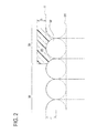
FIG. 2 is an explanatory view showing an enlarged diagram of a part of a coating rod;
FIG. 3 is an explanatory view showing a coating range;
FIG. 4 is an explanatory view showing an enlarged diagram of a part of the coating rod to which a coating material adheres;
FIG. 5 is a graph showing a relationship between a ratio of step-height to coating-thickness and an edge rising amount;
FIG. 6 is an explanatory view showing another example of the coating rod; and
FIG. 7 is an explanatory view showing edge rising.
MODE FOR CARRYING OUT THE INVENTION
A detailed description of a preferred embodiment of the present invention will now be given referring to the accompanying drawings. In the present embodiment, the invention is applied to a method for producing a lithium ion secondary battery and a coating device to be used in this producing method.
The lithium ion secondary battery producing method of the present embodiment is schematically performed by the following steps:
  • (1) An electrode active material layer is formed on a metal foil, thereby producing each of positive and negative electrode plates;
  • (2) The electrode plates produced in (1) and separators are overlapped and wound together to produce a wound body;
  • (3) The wound body is connected to positive and negative electrode terminals;
  • (4) The wound body is inserted in a battery case and then an electrolyte is poured into the battery case; and
  • (5) A liquid inlet is covered to seal the battery case.
The present invention is characterized in the electrode plate producing process in the step (1). The other steps (2) to (5) are all the same as those in a conventional art and thus will not be explained hereinafter. The electrode plate producing process in the step (1) of the present embodiment is a process to form an active material layer on a metal foil which will serve as a current collector sheet of the electrode plate. In this embodiment, the coating material to form the active material layer consists of a first coating material mainly containing a binder and a second coating material containing other materials than the binder. The coating device of the present embodiment is to be used to coat the first coating material on the metal foil which is a base sheet. In the step (1), a coating treatment using the coating device of the present embodiment is followed by a coating treatment of a second coating material using another coating device. The coating treatment of the second coating material is the same as in the conventional art.
A coating device 1 of the present embodiment includes, as shown in FIG. 1, a coating rod 11, a liquid pan 12, and near rolls 13 and 14. This coating device 1 is configured to apply a coating material 21 to a strip-shaped base sheet 20. The coating rod 11 is placed in such a position as to be partly dipped in the liquid pan 12. The space between the liquid pan 12 and the coating rod 11 is filled with the coating material 21. Two near rolls 13 and 14 are arranged in positions on both sides of the coating rod 11 in an advancing direction of the base sheet 20 and in parallel to the coating rod 11.
The coating rod 11 of the present embodiment is formed of a rod 31 and a wire 32 tightly wound on the surface of the rod 31 as shown in FIG. 2. This type of coating rod is called a wire bar. This figure shows an enlarged view of a small portion of the rod 11 near its upper side when viewed in the axial direction being left to right.
A part of the coating rod 11 in the axial direction in the present embodiment is provided as a water repellent section 35 formed with a water-repellent material layer 34 on the surface as shown in FIG. 2. The water repellent section 35 corresponds to a range of the coating rod 11 in the axial direction in which the water-repellent material layer 34 is formed to prevent adhesion of the coating material 21. A portion adjacent on a left side to the water repellent section 35 in the figure is not formed with the water-repellent material layer 34 so that the wire 32 is exposed. The range in which the wire 32 is exposed corresponds to a non-water-repellent section 36. The arrangement of the water repellent section 35 and the non-water-repellent section 36 in the axial direction will be described later.
The water-repellent material layer 34 is a layer made of a water-repellent material coated on the surface of the water repellent section 35 as shown in FIG. 2. In the present embodiment, a water-soluble material is used as the coating material 21. Thus, a water-repellent material is used as a material of the water-repellent material layer 34. In the water repellent section 35, the water-repellent material layer 34 is formed on the entire surface of the coating rod 11 in a circumferential direction. In this figure, the water-repellent material layer 34 is illustrated in a sectional view. As the water-repellent material, preferably, a material having a contact angle of 90° or more to water is used. For example, there are appropriately water-repellent materials such as fluorine resin and general water-repellent materials such as silicone and carbon.
The water-repellent material layer 34 is provided, as shown in FIG. 2, with a height equal to or more than at least a vertex level T of the wire 32 in the radial direction of the coating rod 11. In the present embodiment, furthermore, the surface of the water-repellent material layer 34 is formed as a smooth cylindrical surface. Thus, a step height S between the surface of the water-repellent material layer 34 and the vertex level T of the wire 32 is uniform over the entire circumference of the coating rod 11.
The coating rod 11 in the present embodiment is configured to make the non-water-repellent section 36 hold the coating material 21 and apply the coating material 21 to the base sheet 20. For example, a suitable one as the coating rod 11 in the present embodiment is a rod 31 having a diameter of 10 mm on which a wire 32 having a diameter of 20 to 200 μm is wound. The step height S of the water-repellent material layer 34 is preferably determined to fall within a range of 1 to 100 μm. This is because the step height S of the water-repellent material layer 34 is preferably larger than the thickness of the coating material 21 to be adhered to the base sheet 20. If the step height S of the water-repellent material layer 34 is too large, the base sheet 20 could not properly contact with the coating material 21 held on the non-water repellent section 36. In the present embodiment, furthermore, the surface of the water-repellent material layer 34 is preferably formed with a surface roughness having a maximum height in a range of Ry≦0.1 μm. Excessive surface roughness causes large dynamic friction with the base sheet 20, which may lead to an unstable conveying state of the base sheet 20.
The coating device 1 in the present embodiment is a device arranged to leave uncoated sections Q in end portions on both sides of the base sheet 20 in the width direction and coat a range between the uncoated sections Q located on both sides to form a coated section V, as shown in FIG. 3. This figure schematically shows the range of the base sheet 20 being conveyed from above in the figure to be coated with the coating material 21 by passing across a part of the coating rod 11.
Each of the water repellent sections 35 of the coating rod 11 is provided in a range C including an entire range of the coating rod 11 facing the uncoated section Q and covering a slightly more outside than the width W of the base sheet 20 in the axial direction as shown in FIG. 3. The water repellent sections 35 in the present embodiment are provided at two positions in the axial direction of the coating rod 11. The range between the water repellent sections 35 of the coating rod 11 corresponds to the non-water-repellent section 36. That is, the non-water-repellent section 36 is not formed with the water-repellent material layer 34. The non-water-repellent section 36 is a range facing the coated section V within the width W of the base sheet 20. In other words, the water repellent sections 35 in the present embodiment are arranged adjacent to and on both sides of the non-water-repellent section 36 in the axial direction of the coating rod 11.
The coating rod 11 in the present embodiment is provided with the wire 32 over the entire non-water-repellent section 36 in the axial direction. More preferably, the wire 32 is wound over a wider range than the width W of the base sheet 20. Accordingly, as shown in FIG. 2, in at least an adjacent portion of the water repellent section 35 to the non-water-repellent section 36, the water-repellent material layer 34 is formed to overlap the wire 32.
However, portions more outside than the non-water-repellent section 36 in the axial direction do not necessarily have to be provided with the wire 32. In the portions not provided with the wire 32, the water-repellent material layer 34 is directly formed on the rod 31. In this case, the water-repellent material layer 34 in the relevant portion has a thickness corresponding to the sum of the diameter 2 r of the wire 32 and the step height S.
Next, an explanation will be given to the treatment to apply the coating material 21 containing the binder to the base sheet 20 made of a metal foil by using the coating device 1 in the present embodiment. This coating material 21 is water soluble. In the coating treatment, as shown in FIG. 1, the base sheet 20 is conveyed by winding over the near rolls 13 and 14 to be pressed against the coating rod 11. The coating rod 11 receives rotary drive from a drive source so that a contact portion of the rod 11 moves in the same direction as an advancing direction of the base sheet 20, as indicated by an arrow in the figure. Accordingly, a portion of the coating rod 11 located in an upper side in the figure comes into contact with the base sheet 20.
In the coating treatment, as shown in FIG. 4, the coating material 21 is held in a gap between the adjacent portions of the wire 32 in the non-water-repellent section 36. The coating material 21 is held in the range indicated with dot hatching in the figure. The cross sectional area of this range in the figure depends on the diameter of the rod 31 and the radius r of the wire 32. As an amount of the coating material 21 held on the coating rod 11 is larger, an amount of the coating material 21 to be applied to the base sheet 20 is larger. The larger the amount of the coated coating material 21, the thicker the coating thickness U of the coating material 21 after dried. Consequently, by determining the radius r of the wire 32, it is possible to select the coating thickness U of the coating material 21 to be applied to the base sheet 20. In general, as the radius r of the wire 32 is larger, the coating thickness U is thicker.
On the other hand, each water repellent section 35 is formed, on its surface, with the water-repellent material layer 34 as shown in FIG. 4. This water-repellent material layer 34 is made of a material that repels the coating material 21 as mentioned above. Thus, the coating material 21 does not adhere to the surface of the water repellent section 35. Even if the coating material 21 adheres thereto, the coating material 21 will fall off before it reaches a position where it may contact with the base sheet 20. Accordingly, the coating material 21 is less liable to enter the range of each water repellent section 35. Once formed, the water repellent sections 35 are less likely to be displaced, differently from a masking tape. According to the present embodiment, therefore, the width of the coated section V is stable and fixed.
In the present embodiment, the coating material 21 also somewhat creeps up along the wall surface 35 a of the water repellent section 35 near the wall surface 35 a as shown in FIG. 4. Thus, even in the coating device 1 of the present embodiment, the edge rising phenomenon slightly occurs in both end portions of the completed coated section V. The larger the creeping amount B on the coating rod 11, the higher the edge rising amount Z of the raised edge formed in the coated section V. However, the creeping amount B is smaller than that in the conventional art and thus there is no possibility that the coating material 21 runs up onto the water repellent section 35. This is because the water-repellent material layer 34 is water repellent.
The inventors found that the ratio R of the step height S of the water-repellent material layer 34 to the coating thickness U of the coating material 21 is related to the edge rising amount Z of the coated section V. The coating thickness U of the coating material 21 means an average thickness of a portion other than the edge rising portions of the coating material 21 formed in the coated section V of the coated base sheet 20 (see FIG. 7). The relationship of the edge rising amount Z to the ratio R (R=S/U) between the step height S and the coating thickness U in the coating device 1 of the present embodiment is obtained as shown in HG 5. Specifically, as the ratio R is higher, the edge rising amount Z is larger. Accordingly, an appropriate range of the step height S to restrict the edge rising amount Z within a permissible range is determined based on the relationship with the coating thickness U of the coating material 21 on the base sheet 20.
The permissible range of the edge rising amount Z depends on the property, size, and others of a product to be produced. For instance, in the case where the coating device 1 of the present invention is used as a part of an apparatus for producing an electrode plate, it is preferable that the edge rising amount Z is equal to or less than 400 μm, more preferably, equal to or less than 100 μm. Accordingly, from FIG. 5, the ratio of the step height S to the coating thickness U is preferably equal to or less than 25 and more preferably equal to or less than 8. In the case where the step height S is set to a thickness two or three times as great as the coating thickness U, the edge rising amount Z is a negative value. Specifically, the edges of the coated section V are not raised, but are rather lower than other portions. In this case the edges are low, its permissible range depends on products.
According to the coating rod 11 in the present embodiment, the water-repellent material is coated in the water repellent sections 35 each having the range C shown in FIG. 3, forming the water-repellent material layers 34. Thus, there is no possibility that the coating material 21 is coated in portions that should form the uncoated sections Q of the base sheet 20. On the other hand, the non-water-repellent section 36 facing the coated section V can hold the coating material 21 as shown in FIG. 4. Therefore, one surface of the base sheet 20 is coated with the coating material 21 in a range corresponding to the center coated section V, while both end portions in the width direction are left as the uncoated sections Q.
Furthermore, the water repellent sections 35 in the present embodiment are formed so that the ratio R of the step height S of the water-repellent material layer 34 to the coating thickness U is equal to or less than 25. Accordingly, the edge rising amount Z of each edge formed in the coated section V is equal to or less than 400 μm. As long as the edge rising amount Z is within this range, the base sheet 20 is less likely to be adversely affected even when this coated base sheet 20 is wound. Furthermore, when the water-repellent material layer 34 is formed so that the ratio R of the step height S to the coating thickness U is equal to or less than 8, the coating process can be performed so that the edge rising amount Z be equal to or less than 100 μm.
As the coating rod 11, there are preferably available not only the wire bar but also a rod having a surface formed with a groove(s), a rod having a smooth surface with no wire or groove, a gravure roll to be used for gravure coating, and others. Of them, the rod having a surface formed with grooves is shown in FIG. 6 illustrating a cross section of the grooves. In this illustrated example, corrugated grooves are tightly arranged. These grooves may be formed of circumferential grooves independent from each other or a single groove spirally continuous in a circumferential direction.
In the example shown in FIG. 6, the coating thickness U is determined according to selection of pitch P, depth H, and others of the grooves. In the case where the groove pitch P is constant, the deeper the depth H, the thicker the coating thickness U. In some grooves having different cross sectional shapes, other parameters further influence the coating thickness U. An electrode plate producing device preferably uses a 10-mm-diameter rod formed with grooves at a pitch P between 1 μm and 1000 μm inclusive and at a depth H between 1 μm and 100 μm inclusive. In the rod having a groove or grooves on the outer periphery, the step height S is the thickness of a water-repellent material layer located more radially outside than the level T of a portion formed with no groove(s).
Meanwhile, in addition to the displacement of the coating range and the edge rising, there is a conventional problem with variations in peel strength. This is caused by dynamic friction between the masking tape and the base sheet, resulting in an unstable conveying condition of the base sheet. In the present embodiment, therefore, the surface shape of each water repellent section 35 is determined so that dynamic friction between each water repellent section 35 and the base sheet 20 is minimal. In the present embodiment, specifically, the surface of each water repellent section 35 is formed with a surface roughness determined so that a maximum height is in a range of Ry≦0.1 μm. For instance, the surface of each water repellent section 35 is made very smooth by grinding or the like after coating. According to the coating device 1 of the present embodiment, therefore, the conveying state of the base sheet 20 is maintained stable.
For verification of this respect, the inventors produced an electrode plate of a preferred example by applying the coating device 1 of the present embodiment to a part of a process of producing a negative electrode plate. The inventors compared the degree of variations in peel strength of an active material layer between the electrode plate of the example and an electrode plate produced by the conventional producing method. As long as the conveying state is stable, the variations in peel strength of the active material layer are reduced.
Specifically, the inventors applied a binder layer onto a copper foil by the coating device 1, and then further applied a negative active material layer thereon by another coating device. Thereafter, the coating material was dried. The electrode plate of the example was thus completed. On the other hand, as a comparative example, the inventors produced the electrode plate of the comparative example by use of a coating device using a coating rod provided with no water repellent section 35. In the comparative example, specifically, the inventors applied a binder by the coating device with the coating rod whose ends portions were restricted with masking tapes, as conventionally performed. Other factors of the producing method in the comparative example excepting above are the same manners as those in the preferred example.
Experimental conditions of the example and the comparative example produced in this experiment are as below.
Common Condition:
    • Thickness of a coating liquid for the binder layer: 4 μm
    • Speed of coating the binder layer: 30 m/min
    • Drying after coating of the negative active material layer: 1 zone at 160° C.
The coating device for the negative active material layer is shared between the example and the comparative example.
The coating device for the binder layer in the example includes the coating rod 11 formed with the water repellent sections 35. The range of each water repellent section 35 is set to extend from either end of the coated section V to a position outside by 10 mm from either edge of the base sheet 20.
    • Water-repellent material: Fluorine resin
    • Step height: 10 μm (Ratio R=2.5)
    • Surface roughness of water repellent section: Ry≦0.1 μm
The coating device for the binder layer in the comparative example includes the coating rod formed with no water repellent section. An area covered with the masking tape is from either end of the coated section V to a position inside by 10 mm from either edge of the base sheet 20.
    • Masking tape material: Fluorine resin
    • Masking tape thickness: 50 μm
The inventors measured the peel strength between the active material layer and the base sheet of the electrode plates produced in the example and the comparative example. The experiment was performed on 200 sampled sites. The test conditions are as below
    • Peel strength test device: TACKING TESTER Model TAC II (manufactured by RHESCA Corporation)
    • Advancing speed: 30 mm/min
    • Separating speed: 30 mm/min
    • Pressurizing force: 4 N
Pressurizing time 10 seconds
A maximum tensile stress during separating is assumed as the peel strength. Results of the experiment are shown in the following Table 1.
TABLE 1
Peel Strength Average (N/m) Variations (N/m)
Example 1.70 0.10
Comparative Example 1.65 0.55
As shown in Table 1, the averages of the peel strength are little different between the example and the comparative example. However, the variations in peel strength value are remarkably different between the example and the comparative example. Specifically, according to the coating device 1 of the present embodiment, it is found that an active material layer with less variation in peel strength was formed. In the comparative example, specifically, some portions are easy to peel or separate. In the example, such a portion is not found. This is because the surfaces of the water repellent sections 35 formed to be very smooth ensure a stable conveying state of the base sheet 20.
According to the coating device 1 of the present embodiment explained in detail above, the coating rod 11 is formed with the water repellent sections 35. Thus, the coating material 21 adhering to the ranges of the water repellent sections 35 will drop off from portions of the coating rod 11 not dipped in the liquid pan 12. At the time when contacts with the base sheet 20, the coating material 21 is adhering to only the range of the rod 11 facing the coated section V. Of the coating rod 11, the portions facing the uncoated sections Q are not adhered with the coating material 21. Therefore, when the coating rod 11 is placed in contact with the base sheet 20, only the range of the coated section V is coated.
Furthermore, the step height S of each water repellent section 35 is set to be equal to or less than a height twenty-five times as high as the coating thickness U of the coating material 21. Accordingly, the creeping amount B of the coating material 21 on the wall surface 35 a of each water repellent section 35 falls within a permissible range. Thus, the edge rising amount Z of each edge rising portion formed in the coated section V also falls within a permissible range.
Furthermore, the surface of each water repellent section 35 is very smooth and thus the dynamic friction between the water repellent sections 35 and the base sheet 20 is small. This allows the base sheet 20 to be conveyed in a stable state. Accordingly, a uniform coating state is maintained. In the present embodiment, specifically, the coating device 1 is configured to bring the coating rod 11 into contact with the base sheet 20 to coat the base sheet 20, thereby appropriately forming the uncoated sections Q in the end portions of the base sheet 20 in the width direction and uniformly coating the coated section V. Consequently, when a battery is manufactured to include the electrode plate produced by use of the coating device 1 of the present embodiment, the manufactured battery can provide excellent performance.
The above embodiment is a mere example and does not impart any limitation to the present invention. Thus, the present invention may be embodied in other specific forms without departing from the essential characteristics thereof. For instance, the above embodiment shows the device for producing the electrode plate formed with the uncoated sections on both sides of the base sheet in the width direction. However, the uncoated sections on both sides do not always need to be equal in width to each other. The uncoated sections may be formed with different widths on both sides in the width direction or only one uncoated section may be formed on either one side in the width direction. The present invention is also applicable to a coating device arranged to produce an electrode plate formed with an uncoated section(s) between coated sections in addition to the uncoated sections on both sides. This configuration can provide the same effects as above as long as the water repellent sections are appropriately formed in the ranges each facing an area of an uncoated section of a base sheet.
REFERENCE SIGNS LIST
  • 1 Coating device
  • 11 Coating rod
  • 20 Base sheet
  • 21 Coating material
  • 34 Water-repellent material layer
  • 35 Water repellent section
  • 36 Non-water-repellent section

Claims (4)

The invention claimed is:
1. A method for producing an electrode plate, the method using a rod and a liquid pan and including driving the rod to rotate while bringing the rod into partial contact with coating material filled between the rod and the liquid pan to hold the coating material on a surface of the rod, and bringing a strip-shaped base sheet into contact with the coating material held on the rod while conveying the base sheet in a longitudinal direction, to apply the coating material to a coated section of the base sheet by leaving an uncoated section in a width direction,
wherein the method uses the rod including:
a plurality of recesses formed on the surface and spaced from each other along a longitudinal direction of the rod;
a water repellent section in which water-repellent material that repels the coating material is coated on an entire circumference of a part of the rod in an axial direction overlapping at least one of the recesses; and
a non-water-repellent section including an uncoated section of at least one the recesses and arranged adjacent to the water repellent section and not coated with the water-repellent material, and
the non-water repellent section is placed to face the coated section, and the coating material is water soluble and contains binder.
2. The method for producing an electrode plate according to claim 1, wherein the method uses the rod provided with the water repellent section extending to a more outside portion in the axial direction than a portion facing an end portion of the base sheet in a width direction to form an uncoated section applied with no coating material on each end portion of the base sheet in the width direction.
3. The method according to claim 1, wherein the rod is a wire-wrapped rod, and the plurality of recesses are formed between wires.
4. The method according to claim 1, wherein the rod includes a plurality of grooves defining the plurality of recesses or a single spiral groove defining the plurality of recesses.
US13/823,393 2010-12-24 2010-12-24 Method for producing electrode plate Active US9225004B2 (en)

Applications Claiming Priority (1)

Application Number Priority Date Filing Date Title
PCT/JP2010/073282 WO2012086047A1 (en) 2010-12-24 2010-12-24 Coating device and method for producing electrode plate

Publications (2)

Publication Number Publication Date
US20130260017A1 US20130260017A1 (en) 2013-10-03
US9225004B2 true US9225004B2 (en) 2015-12-29

Family

ID=46313348

Family Applications (1)

Application Number Title Priority Date Filing Date
US13/823,393 Active US9225004B2 (en) 2010-12-24 2010-12-24 Method for producing electrode plate

Country Status (5)

Country Link
US (1) US9225004B2 (en)
JP (1) JP5293839B2 (en)
KR (2) KR20150034284A (en)
CN (1) CN103282129B (en)
WO (1) WO2012086047A1 (en)

Cited By (1)

* Cited by examiner, † Cited by third party
Publication number Priority date Publication date Assignee Title
US10632490B2 (en) * 2015-03-17 2020-04-28 Maan Intellectual Properties B.V. Device for applying a hot-melt to a web of material

Families Citing this family (5)

* Cited by examiner, † Cited by third party
Publication number Priority date Publication date Assignee Title
CN107413576A (en) * 2017-08-03 2017-12-01 深圳市旭然电子有限公司 Coating apparatus
CN107331875B (en) * 2017-08-14 2023-04-18 福建亚南电机有限公司 Carbon paper hydrophobic treatment equipment
EP4349496A2 (en) * 2018-03-15 2024-04-10 IO Tech Group, Ltd. Multi-material dispensing and coating systems
CN112892988A (en) * 2021-01-19 2021-06-04 兰州大学 Coating device for electrode plate of lithium ion battery
CN113102193B (en) * 2021-03-04 2022-04-26 南昌大学 Coating machine scraper based on surface hydrophilic and hydrophobic microstructure

Citations (18)

* Cited by examiner, † Cited by third party
Publication number Priority date Publication date Assignee Title
US4263870A (en) * 1976-08-12 1981-04-28 Fuji Photo Film Co., Ltd. Coating process
JPH07156525A (en) 1993-12-07 1995-06-20 Dainippon Printing Co Ltd Pattern forming method
US5922402A (en) * 1996-02-15 1999-07-13 Speeney; Michael J. Method of making adhesive tape with adhesive free zones
US6045947A (en) 1995-11-11 2000-04-04 Dai Nippon Printing Co., Ltd. Electrode plate for secondary battery with nonaqueous electrolyte and method of manufacturing the same
JP2000202358A (en) 1999-01-18 2000-07-25 Matsushita Electric Ind Co Ltd Coating
JP2005111299A (en) 2003-10-02 2005-04-28 Fuji Photo Film Co Ltd Coating rod and method for manufacturing the same
JP2005131512A (en) 2003-10-29 2005-05-26 Osg Corp Coating rod
US20050221010A1 (en) * 2004-04-06 2005-10-06 Fuji Photo Film Co., Ltd. Coating material applying method and apparatus with bar
US20060068166A1 (en) * 2004-09-29 2006-03-30 Fuji Photo Film Co., Ltd. Coating method, coating apparatus and coated medium
US20070141263A1 (en) * 2002-10-14 2007-06-21 Hans-Jurgen Schaefer Process and an apparatus for coating printed circuit boards with laser-structurable, thermally curable solder stop lacquers and electroresists
US20070269600A1 (en) 2006-05-12 2007-11-22 Gozdz Antoni S Apparatus and method for processing a coated sheet
US20070281072A1 (en) * 2006-06-06 2007-12-06 Boston Scientific Scimed, Inc. Coating a workpiece using a metering device and workpieces coated with this metering device
JP2008166113A (en) 2006-12-28 2008-07-17 Matsushita Electric Ind Co Ltd Manufacturing method of electrode for battery, and manufacturing apparatus of electrode for battery
JP2009247985A (en) 2008-04-07 2009-10-29 Toyota Motor Corp Coating device and coating method
US7790218B2 (en) * 2006-03-30 2010-09-07 Panasonic Corporation Method and apparatus for forming electrode for battery
US8039044B2 (en) * 2006-03-30 2011-10-18 Panasonic Corporation Method for forming electrode for battery
US20120318192A1 (en) * 2011-06-17 2012-12-20 Nobuyuki Yamazaki Application roller and manufacturing method of application roller
US8361554B2 (en) * 2006-11-29 2013-01-29 Fujifilm Corporation Apparatus and method for bar coating

Family Cites Families (2)

* Cited by examiner, † Cited by third party
Publication number Priority date Publication date Assignee Title
JPH07155680A (en) * 1993-11-30 1995-06-20 Ricoh Co Ltd Bar coating
JP4601918B2 (en) * 2003-05-30 2010-12-22 大日本印刷株式会社 COATING DIE HEAD, COATING DEVICE, AND METHOD FOR PRODUCING COATING DIE HEAD

Patent Citations (24)

* Cited by examiner, † Cited by third party
Publication number Priority date Publication date Assignee Title
US4263870A (en) * 1976-08-12 1981-04-28 Fuji Photo Film Co., Ltd. Coating process
JPH07156525A (en) 1993-12-07 1995-06-20 Dainippon Printing Co Ltd Pattern forming method
US6045947A (en) 1995-11-11 2000-04-04 Dai Nippon Printing Co., Ltd. Electrode plate for secondary battery with nonaqueous electrolyte and method of manufacturing the same
JP3553244B2 (en) 1995-11-11 2004-08-11 大日本印刷株式会社 Method for producing electrode plate for non-aqueous electrolyte secondary battery
US5922402A (en) * 1996-02-15 1999-07-13 Speeney; Michael J. Method of making adhesive tape with adhesive free zones
JP2000202358A (en) 1999-01-18 2000-07-25 Matsushita Electric Ind Co Ltd Coating
US20070141263A1 (en) * 2002-10-14 2007-06-21 Hans-Jurgen Schaefer Process and an apparatus for coating printed circuit boards with laser-structurable, thermally curable solder stop lacquers and electroresists
JP2005111299A (en) 2003-10-02 2005-04-28 Fuji Photo Film Co Ltd Coating rod and method for manufacturing the same
US20050109272A1 (en) 2003-10-02 2005-05-26 Atsushi Ooshima Coating rod and producing method therefor
US20080276861A1 (en) 2003-10-02 2008-11-13 Atsushi Ooshima Coating rod and producing method therefor
JP2005131512A (en) 2003-10-29 2005-05-26 Osg Corp Coating rod
US20050221010A1 (en) * 2004-04-06 2005-10-06 Fuji Photo Film Co., Ltd. Coating material applying method and apparatus with bar
US20060068166A1 (en) * 2004-09-29 2006-03-30 Fuji Photo Film Co., Ltd. Coating method, coating apparatus and coated medium
US8039044B2 (en) * 2006-03-30 2011-10-18 Panasonic Corporation Method for forming electrode for battery
US7790218B2 (en) * 2006-03-30 2010-09-07 Panasonic Corporation Method and apparatus for forming electrode for battery
US20070269600A1 (en) 2006-05-12 2007-11-22 Gozdz Antoni S Apparatus and method for processing a coated sheet
KR20090010083A (en) 2006-05-12 2009-01-28 에이일이삼 시스템즈 인코포레이티드 Apparatus and method for processing a coated sheet
US20070281072A1 (en) * 2006-06-06 2007-12-06 Boston Scientific Scimed, Inc. Coating a workpiece using a metering device and workpieces coated with this metering device
US8361554B2 (en) * 2006-11-29 2013-01-29 Fujifilm Corporation Apparatus and method for bar coating
US20100062146A1 (en) 2006-12-28 2010-03-11 Tetsuya Hayashi Method for producing battery electrode and apparatus for producing battery electrode
JP2008166113A (en) 2006-12-28 2008-07-17 Matsushita Electric Ind Co Ltd Manufacturing method of electrode for battery, and manufacturing apparatus of electrode for battery
JP2009247985A (en) 2008-04-07 2009-10-29 Toyota Motor Corp Coating device and coating method
US20120183681A1 (en) * 2008-04-07 2012-07-19 Masakazu Umebara Application apparatus and application method
US20120318192A1 (en) * 2011-06-17 2012-12-20 Nobuyuki Yamazaki Application roller and manufacturing method of application roller

Cited By (1)

* Cited by examiner, † Cited by third party
Publication number Priority date Publication date Assignee Title
US10632490B2 (en) * 2015-03-17 2020-04-28 Maan Intellectual Properties B.V. Device for applying a hot-melt to a web of material

Also Published As

Publication number Publication date
CN103282129A (en) 2013-09-04
JP5293839B2 (en) 2013-09-18
WO2012086047A1 (en) 2012-06-28
JPWO2012086047A1 (en) 2014-05-22
KR20150034284A (en) 2015-04-02
US20130260017A1 (en) 2013-10-03
KR20130114185A (en) 2013-10-16
CN103282129B (en) 2016-06-22

Similar Documents

Publication Publication Date Title
US9225004B2 (en) Method for producing electrode plate
JP6524307B2 (en) Method of manufacturing separator
US8163332B2 (en) Electrode manufacturing apparatus and electrode manufacturing method
US20080083367A1 (en) Gravure coating apparatus
WO2013137385A1 (en) Electrode, method for producing same, and device for producing same
WO2014122847A1 (en) Non-aqueous electrolyte secondary battery, method for manufacturing positive electrode sheet of non-aqueous electrolyte secondary battery, and method for manufacturing non-aqueous electrolyte secondary battery
US20130260019A1 (en) Layer-on-layer coating device and double-sided coating device, method for producing electrode plates, and method for producing batteries
JP5830226B2 (en) Manufacturing method and coating apparatus of metal foil with coating film
JP2015013248A (en) Coating device and electrode manufacturing method
JP2005183181A (en) Electrode plate for nonaqueous electrolyte secondary battery and manufacturing method of the same
JP2000323129A (en) Manufacture of battery electrode
US10991932B2 (en) Rolling device for electrode
JP2002184394A (en) Sheet material rolling method
US20230163341A1 (en) Electrode Manufacturing Apparatus
JP2016131944A (en) Gravure coating apparatus
JP3893731B2 (en) Intermittent application device
US20190013511A1 (en) Electrode sheet manufacturing method
JP2002304988A (en) Manufacturing method for battery electrode
JP5609839B2 (en) Method for producing electrode plate for lithium ion secondary battery
JP2018122233A (en) Gravure coating device
JP2007265698A (en) Manufacturing method of electrode for nonaqueous electrolyte secondary battery
JP2014026816A (en) Method of manufacturing electrode and power storage device and secondary battery
JP2018122232A (en) Gravure coating device
JPH11317220A (en) Production of sheet electrode
JP2015182027A (en) coating apparatus

Legal Events

Date Code Title Description
AS Assignment

Owner name: TOYOTA JIDOSHA KABUSHIKI KAISHA, JAPAN

Free format text: ASSIGNMENT OF ASSIGNORS INTEREST;ASSIGNOR:YAMAZAKI, NOBUYUKI;REEL/FRAME:029999/0253

Effective date: 20130306

STCF Information on status: patent grant

Free format text: PATENTED CASE

MAFP Maintenance fee payment

Free format text: PAYMENT OF MAINTENANCE FEE, 4TH YEAR, LARGE ENTITY (ORIGINAL EVENT CODE: M1551); ENTITY STATUS OF PATENT OWNER: LARGE ENTITY

Year of fee payment: 4

MAFP Maintenance fee payment

Free format text: PAYMENT OF MAINTENANCE FEE, 8TH YEAR, LARGE ENTITY (ORIGINAL EVENT CODE: M1552); ENTITY STATUS OF PATENT OWNER: LARGE ENTITY

Year of fee payment: 8