US9215292B2 - Information processing apparatus, data distribution system, method of controlling information processing apparatus, and storage medium - Google Patents
Information processing apparatus, data distribution system, method of controlling information processing apparatus, and storage medium Download PDFInfo
- Publication number
- US9215292B2 US9215292B2 US13/949,476 US201313949476A US9215292B2 US 9215292 B2 US9215292 B2 US 9215292B2 US 201313949476 A US201313949476 A US 201313949476A US 9215292 B2 US9215292 B2 US 9215292B2
- Authority
- US
- United States
- Prior art keywords
- information processing
- data
- processing apparatus
- data amount
- generation condition
- Prior art date
- Legal status (The legal status is an assumption and is not a legal conclusion. Google has not performed a legal analysis and makes no representation as to the accuracy of the status listed.)
- Expired - Fee Related, expires
Links
- 230000010365 information processing Effects 0.000 title claims abstract description 126
- 238000000034 method Methods 0.000 title claims description 28
- 238000012545 processing Methods 0.000 claims abstract description 77
- 230000008859 change Effects 0.000 claims abstract description 47
- 238000009795 derivation Methods 0.000 claims abstract description 8
- 238000001514 detection method Methods 0.000 claims abstract description 7
- 230000014759 maintenance of location Effects 0.000 claims description 21
- 230000000007 visual effect Effects 0.000 claims 1
- 230000006870 function Effects 0.000 description 25
- 238000007405 data analysis Methods 0.000 description 24
- 230000005540 biological transmission Effects 0.000 description 23
- 238000007726 management method Methods 0.000 description 22
- 238000013523 data management Methods 0.000 description 6
- 230000008569 process Effects 0.000 description 6
- 230000000717 retained effect Effects 0.000 description 6
- 238000003384 imaging method Methods 0.000 description 5
- 230000009467 reduction Effects 0.000 description 5
- 238000004364 calculation method Methods 0.000 description 4
- 238000010586 diagram Methods 0.000 description 4
- 238000012546 transfer Methods 0.000 description 4
- 230000003044 adaptive effect Effects 0.000 description 2
- 238000004891 communication Methods 0.000 description 2
- 239000000470 constituent Substances 0.000 description 2
- 238000005516 engineering process Methods 0.000 description 2
- 230000006872 improvement Effects 0.000 description 2
- 230000004043 responsiveness Effects 0.000 description 2
- 230000008901 benefit Effects 0.000 description 1
- 230000004397 blinking Effects 0.000 description 1
- 238000012508 change request Methods 0.000 description 1
- 230000006835 compression Effects 0.000 description 1
- 238000007906 compression Methods 0.000 description 1
- 238000012986 modification Methods 0.000 description 1
- 230000004048 modification Effects 0.000 description 1
- 230000006855 networking Effects 0.000 description 1
- 230000003287 optical effect Effects 0.000 description 1
- 230000002123 temporal effect Effects 0.000 description 1
Images


Classifications
-
- H—ELECTRICITY
- H04—ELECTRIC COMMUNICATION TECHNIQUE
- H04L—TRANSMISSION OF DIGITAL INFORMATION, e.g. TELEGRAPHIC COMMUNICATION
- H04L67/00—Network arrangements or protocols for supporting network services or applications
- H04L67/50—Network services
- H04L67/60—Scheduling or organising the servicing of application requests, e.g. requests for application data transmissions using the analysis and optimisation of the required network resources
-
- H—ELECTRICITY
- H04—ELECTRIC COMMUNICATION TECHNIQUE
- H04L—TRANSMISSION OF DIGITAL INFORMATION, e.g. TELEGRAPHIC COMMUNICATION
- H04L47/00—Traffic control in data switching networks
-
- H04L67/32—
-
- H04L29/08144—
-
- H—ELECTRICITY
- H04—ELECTRIC COMMUNICATION TECHNIQUE
- H04L—TRANSMISSION OF DIGITAL INFORMATION, e.g. TELEGRAPHIC COMMUNICATION
- H04L67/00—Network arrangements or protocols for supporting network services or applications
- H04L67/01—Protocols
- H04L67/10—Protocols in which an application is distributed across nodes in the network
- H04L67/1001—Protocols in which an application is distributed across nodes in the network for accessing one among a plurality of replicated servers
-
- H04L29/08072—
-
- H—ELECTRICITY
- H04—ELECTRIC COMMUNICATION TECHNIQUE
- H04L—TRANSMISSION OF DIGITAL INFORMATION, e.g. TELEGRAPHIC COMMUNICATION
- H04L69/00—Network arrangements, protocols or services independent of the application payload and not provided for in the other groups of this subclass
- H04L69/30—Definitions, standards or architectural aspects of layered protocol stacks
- H04L69/32—Architecture of open systems interconnection [OSI] 7-layer type protocol stacks, e.g. the interfaces between the data link level and the physical level
- H04L69/322—Intralayer communication protocols among peer entities or protocol data unit [PDU] definitions
- H04L69/329—Intralayer communication protocols among peer entities or protocol data unit [PDU] definitions in the application layer [OSI layer 7]
Definitions
- the present invention relates to a data distribution system that makes data upload and download possible for a plurality of client devices connected to a server device via a network, and to a control method thereof.
- URL is an abbreviation for Uniform Resource Locator, and is a describing method for indicating a location of data that exists on the Internet.
- a URL comprises an information access scheme, a server address, a port number, a path, and the like.
- HTTP is an abbreviation for Hypertext Transfer Protocol, and is a protocol used when a server device and a client device transmit and receive data specified by a URL.
- HTTP is an abbreviation for Hypertext Transfer Protocol, and is a protocol used when a server device and a client device transmit and receive data specified by a URL.
- HTTP is an abbreviation for Hypertext Transfer Protocol, and is a protocol used when a server device and a client device transmit and receive data specified by a URL.
- Various data exchange can be performed between a server device and a client device with HTTP.
- image SNS service an image streaming social network service
- stream a sequential flow
- client devices that successively transmit images
- the following technique is presented in order to address the challenge of having not only a server device but also a client device handle a particular role in order for the system on the whole to efficiently process an increasing number of processing requests.
- the technique recited in Japanese Patent Laid-Open No. 2003-008977 has an object of generating advice information on the server device based on an image that a camera uploaded, and changing target camera settings based on that information.
- the settings of the client device camera are changed based on information that the camera itself captured, and are not updated based on a load of the server device, or the like. Accordingly, in the technique recited in Japanese Patent Laid-Open No. 2003-008977, changing of client device settings in accordance with a load status on a server device side cannot be carried out.
- Some embodiments of the present invention provides a data distribution system for improving processing efficiency for a system on the whole by adjusting processing on a client device side in accordance with a current load status of a server device, and a control method thereof.
- a data distribution system has a plurality of information processing terminals and an information processing apparatus which is connected to the plurality of information processing terminals via a network
- the information processing apparatus comprises: an acquisition unit configured to acquire data that is uploaded from at least one of the plurality of information processing terminals; a detection unit configured to detect connection status information of the plurality of information processing terminals and a generation condition for data in the information processing terminals; a derivation unit configure to derive a predicted data amount predicted to be uploaded in a unit time to the information processing apparatus and a processable data amount that the information processing apparatus is capable of processing in a unit time based on at least one of the connection status information or the generation condition; and a request unit configured to make a request to at least one information processing terminal, in a case where the predicted data amount exceeds the processable data amount, to change the generation condition for data in the at least one information processing terminal in order to lower a data amount.
- a method of controlling an information processing apparatus which is connected to a plurality of information processing terminals via a network comprises acquiring data that is uploaded from at least one of the plurality of information processing terminals; detecting connection status information of the plurality of information processing terminals and a generation condition for data in the information processing terminals; deriving a predicted data amount predicted to be uploaded in a unit time to the information processing apparatus and a processable data amount that the information processing apparatus is capable of processing in a unit time based on at least one of the connection status information or the generation condition; and making a request to at least one information processing terminal, in a case where the predicted data amount exceeds the processable data amount, to change the generation condition for data in the at least one information processing terminal in order to lower a data amount.
- a non-transitory computer-readable storage medium stores a program for causing a computer which is connected to a plurality of information processing terminals via a network to: acquire data that is uploaded from at least one of the plurality of information processing terminals; detect connection status information of the plurality of information processing terminals and a generation condition for data in the information processing terminals; derive a predicted data amount predicted to be uploaded in a unit time to the information processing apparatus and a processable data amount that the information processing apparatus is capable of processing in a unit time based on at least one of the connection status information or the generation condition; and make a request to at least one information processing terminal, in a case where the predicted data amount exceeds the processable data amount, to change the generation condition for data in the at least one information processing terminal in order to lower a data amount.
- FIG. 1 is a block view for showing a hardware configuration of a client device and a server device in a data distribution system of one embodiment of the present invention.
- FIG. 2 is a block diagram for showing a main functional configuration of the client device of the present embodiment.
- FIG. 3 is a block diagram for showing a main functional configuration of the server device on the present embodiment.
- FIG. 4 is a view for showing a processing sequence between client devices in a case where the server device does not perform a load adjustment.
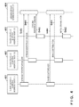
- FIG. 5 is a view for showing an example of a processing sequence between client devices in a case where the server device does perform a load adjustment.
- FIG. 6 is a view for showing a structure of data for stream management in the server device.
- FIG. 7 is a view for showing a structure of data for client device management in the server device.
- FIG. 8 is a flowchart for describing load adjustment processing in the server device.
- FIG. 9 is a view for showing an example of an operation/display panel in a case where the client device is a digital camera in a fourth embodiment.
- FIG. 10 is a view for showing an example of a processing sequence between the server device and the client device in a fifth embodiment.
- processing efficiency can be improved for the system on the whole by adjusting a processing condition of the client device in accordance with a load status of the server device.
- the present invention relates to a data distribution system that realizes an image SNS service.
- a plurality of client devices are connected via a network to the server device, and data uploaded from a first client device to the server device is downloaded to a second client device.
- One embodiment realizes following functions to improve for improving processing efficiency for the system on the whole by adjusting a data generation condition on the client device side in accordance with the current load status of the server device. Firstly, number-of-devices information and upload frequency information of first and second client devices that perform upload and download is acquired. Furthermore, an upload target data generation condition preset for each client device that performs upload is acquired.
- a predicted load that will occur due to data distribution by the server device is calculated. Furthermore, according to the load status due to processing other than data distribution by the server device, the number-of-devices information, the frequency information and the generation condition, a target load relating to data distribution by the server device is calculated. Next, in order that the predicted load satisfy the target load, the generation condition on the first client device is changed.
- FIG. 1 is a block view for showing a hardware configuration of a computer apparatus 100 used as a client device and as a server device in a data distribution system of one embodiment of the present invention.
- numeral 101 denotes a Central Processing Unit (CPU) for controlling the computer apparatus 100 on the whole.
- Numeral 102 denotes a Read Only Memory (ROM) for storing programs and parameters that do not need to be changed.
- Numeral 103 denotes a Random Access Memory (RAM) for temporarily storing programs and data provided from external apparatuses and the like.
- Numeral 104 denotes an external storage apparatus that may include a hard disk, a memory card or the like connected to the computer apparatus 100 .
- Numeral 105 denotes an interface (I/F) with an input device (not shown) for receiving user operations and inputting data such as a pointing device or a keyboard.
- Numeral 106 denotes an I/F with an output apparatus (not shown) for displaying data that the computer apparatus 100 maintains and supplied data.
- Numeral 107 denotes a network I/F for connecting a network line (not shown) to the Internet or the like.
- Numeral 108 denotes a system bus connected so that each of the units 101 through 107 can communicate with each other.
- FIG. 2 is a block diagram for showing a main functional configuration in a case where the computer apparatus 100 shown in FIG. 1 is used as the client device 200 .
- a digital camera which is an image capturing device capable of capturing still images and video is assumed.
- the client device 200 is identified by other devices by device identification unit having a function for identifying a particular device as is typified by an IP address.
- device identification unit having a function for identifying a particular device as is typified by an IP address.
- a client OS unit 201 enables software to handle each type of hardware constituent element constituting the client device 200 abstractly as computer resources. Because the client OS unit 201 exists, other software components that operate on the client device 200 need not perform direct control of hardware.
- a client application unit 202 has functions that are unique to the type of the client device 200 , and functions that are provided to a user. Here, because the client device 200 is a digital camera, functions such as image capture/save/edit/display, and control of settings related to image capture can be considered to be the functions unique to the type of device.
- the client application unit 202 is software for realizing these functions.
- a client data analysis unit 203 analyzes data transmission requests from the client application unit 202 , transfers them to a client data transmission unit 204 , and also analyzes processing requested from a client data receiving unit 207 and transfers it to the client application unit 202 .
- the client application unit 202 performs a data transmission request via a network to the server device
- the client data analysis unit 203 accepts the request.
- the client data transmission unit 204 drives hardware that performs network processing via the client OS unit 201 .
- the client data transmission unit 204 converts a format of data that the client application unit 202 requests into a format that can be processed.
- the client application unit 202 makes a request to the client data analysis unit 203 to upload a processing target image as a file to be saved in a particular logical group (stream) that the server device on the network provides.
- the client data analysis unit 203 analyzes this request, and generates transmission data including a host name and IP address corresponding to the actual server device, a transmission destination address end point URL and image information in a format conforming to HTTP.
- the client data analysis unit 203 adds data to/acquires data from the server device having a specific address in this way.
- the client data analysis unit 203 having received a request from the client application unit 202 , also realizes a function for transmitting setting information related to capture to the server device that the client application unit 202 manages.
- the client data transmission unit 204 transfers the processing request from the client data analysis unit 203 to the client OS unit 201 .
- the client OS unit 201 is controlled based on the transmission destination and the transmission data that the client data analysis unit 203 converted. Specifically, the control of establishing a TCP/IP session and transmitting actual HTTP data is performed.
- a client data management unit 205 manages data (target data) that the client application unit 202 handles using a client data retention unit 206 .
- the client data retention unit 206 is, specifically, a non-volatile memory or a hard disk built into the device, and a storage region for actually retaining data is controlled by the client data management unit 205 .
- target data in the client device 200 is, specifically, captured image data.
- the client data receiving unit 207 receives requests dispatched from the server device. A request from the server device on the network is received via the client OS unit 201 , and reaches the client data receiving unit 207 . The client data receiving unit 207 , having received the data, transmits it to the client data analysis unit 203 .
- the client data analysis unit 203 Here, explanation will be given for processing in a case where there was an HTTP connection from the server device on TCP/IP port number 80 which the client OS unit 201 set up. In this case, analyzing an HTTP URL or header, or a payload, or the like, and transmitting to the client data analysis unit 203 are roles of the client data receiving unit 207 .
- the client data analysis unit 203 having received the data, analyzes its content, organizes information that should be processed and transmits to the client application unit 202 . For example, setting information related to capture requested by the server device is received via the client data receiving unit 207 and the request content is transmitted, having been converted to a format that the client application unit 202 can interpret.
- the client device 200 by taking the above described software configuration, not only transmits requests and data to the server device on the network, but also has a function by which it can receive and process a request from the server device.
- the client application unit 202 in the client device 200 also has a function for participating in an image SNS service that the server device provides.
- the server device provides information for identifying logical unit streams for sharing image data via the network to the client application unit 202 .
- the client application unit 202 of the client device 200 participates in the following two roles with respect to streams provided by the server device.
- First is the role of performing browsing without performing provision of images to the stream.
- the client device 200 is not necessarily a digital camera, and may be a normal portable terminal, a display apparatus, or the like.
- the other role is of performing not just browsing but also adding of an image to the stream in a case where the client device 200 is a device that has an image generation capability such as a digital camera.
- the client application unit 202 determines by what kind of role and what kind of stream to participate in.
- FIG. 3 is a block diagram for showing a main functional configuration in a case where the computer apparatus 100 shown in above described FIG. 1 is used as the server device 300 .
- a device for providing an image stream type social networking service (image SNS service) that shares captured images in real time using a digital camera which is a client device 200 that supports a network is assumed for the server device 300 .
- image SNS service On the image SNS service, a plurality of photographs captured by a plurality of users can be shared between client devices (between users) as a sequential flow (stream).
- the server device 300 has a function for handling images almost in real time between the plurality of client devices.
- the server device 300 is identified by other devices by device identification unit having a function for identifying a particular device as is typified by an IP address.
- device identification unit having a function for identifying a particular device as is typified by an IP address.
- a server OS unit 301 enables software to handle each type of hardware constituent element constituting the server device 300 abstractly as computer resources and has functions that are basically similar to the client OS unit 201 of the client device 200 . Because the server OS unit 301 exists, other software components that operate on the server device 300 need not perform direct control of hardware.
- the server OS unit 301 is able to determine a processing status of the CPU 101 , the system bus 108 , the network I/F 107 and the like within the apparatus (shown in FIG. 1 ) when it is necessary to perform control related to hardware of the server device 300 .
- the server OS unit 301 can report a status of the processing load in each part of hardware that constitutes the server device 300 which is the computer apparatus 100 in accordance with a request of other software comprised in the server device 300 .
- a server application unit 302 has functions that are unique to the image SNS service in the server device 300 , and specifically is software for performing control of streaming management/receiving/saving/searching/transmitting images for streaming, and so on. Details of processing performed in the server application unit 302 will be explained later using FIG. 4 , FIG. 5 and FIG. 8 .
- a server data analysis unit 303 receives a data analysis request from the server application unit 302 and makes a request for processing to a server data transmission unit 304 .
- the server application unit 302 makes a data transmission request to the client device via the network
- the server data analysis unit 303 receives that request.
- the server data transmission unit 304 drives hardware for performing network processing via the server OS unit 301 .
- the server data analysis unit 303 performs processing for converting a format of data that the server application unit 302 requests into a format that the server data transmission unit 304 can process.
- the server application unit 302 determines that it is necessary to change setting information related to capturing for a specific client device, the following processing is performed.
- the server application unit 302 transmits information related to a device identification unit for identifying the specific client device and setting change contents to the server data analysis unit 303 .
- the server data analysis unit 303 analyzes this request and generates a transmission destination address which is an actual host name and IP access corresponding to the client device and transmission data in a format that the client device can receive.
- the server data transmission unit 304 transmits the processing request from the server data analysis unit 303 to the server OS unit 301 .
- the server data analysis unit 303 controls the server OS unit 301 based on the transmission destination address and transmission data that it converted. Specifically, control of establishing a TCP/IP session and transmitting the actual data is performed.
- a server data management unit 305 manages main data retained by the server device 300 .
- a server control data retention unit 308 retains data related to load distribution control of the server device 300 and the client devices. Details of data retained by the server control data retention unit 308 will be explained later using FIG. 6 and FIG. 7 .
- a server shared data retention unit 306 retains logical unit streams for sharing images via the server device 300 amongst client devices and data shared between client devices. The server control data retention unit 308 and the server shared data retention unit 306 perform saving of data using non-volatile memory or a hard disk connected to the server device 300 .
- a server data receiving unit 307 receives requests dispatched from the client device.
- a request from the client device on the network is received via the server OS unit 301 and reaches the server data receiving unit 307 .
- the server data receiving unit 307 having received the data, converts it into a format that the server data analysis unit 303 can process.
- explanation will be give for processing in the case where there was an HTTP connection from an external device to the server OS unit 301 on the TCP/IP port number 80 .
- analyzing an HTTP URL and header or a payload or the like, and transferring to the server data analysis unit 303 are roles of the server data receiving unit 307 .
- the server device 300 can provide multiple streams to the client device, each stream being a unit to which logical data flows are grouped.
- Information needed to configure such a stream (stream information) is stored in the server control data retention unit 308 and managed by the server data management unit 305 .
- Stream information may be such things as, for example, a list of client devices that are currently participating in the stream or a list of images that are saved in the stream.
- the server device 300 by taking the above described configuration, not only receives requests from a client device on the network but also has a function by which it can cause processing to be performed by transmitting a request to the client device.
- the server application unit 302 provides multiple streams to the client device by controlling the server data analysis unit 303 according to information retained in the server control data retention unit 308 that the server data management unit 305 manages. Unique identifier information is attached to each stream and stored in the server control data retention unit 308 .
- the client device can identify a stream that it is participating in by this identification information. Also, the server device determines whether the client device performs image data adding (upload) or only performs acquisition (download), and records the result of this determination along with device identification information for identifying the client device into the server control data retention unit 308 .
- the server application unit 302 determines whether image generation condition (conditions for generating images to be added or added-image conditions) settings should be changed in each client device from a status of the current processing load acquired from the server OS unit 301 and data stored in the server control data retention unit 308 . Also the server application unit 302 can make a request that the added-image conditions be changed to each client via the server data analysis unit 303 and the server data transmission unit 304 .
- FIG. 4 a processing sequence for a case where the server device does not perform load adjustment is shown in FIG. 4 .
- numerals 401 , 402 and 403 denote client devices A, B and C, and the configuration of each of these is shown as the client device 200 in FIG. 2 .
- the client device A 401 and the client device B 402 are cameras having an imaging capability
- the client device C 403 is a display that does not have an imaging capability.
- Numeral 404 denotes the server device having a function for providing an image SNS service and whose configuration is shown as the server device 300 in FIG. 3 .
- the client devices A 401 , B 402 and C 403 and the server device 404 are identified by the IP addresses shown respectively in FIG. 4 .
- step S 450 the client device A 401 identifies a stream that the image SNS service of the server device 404 provides, and joins it.
- the client device B 402 in step S 451
- the client device C 403 in step S 452 , join the stream that the image SNS service of the server device 404 provides.
- the client device A 401 makes a request to the server device 404 for adding of a captured image to the stream that it joined.
- the server device 404 having received the request, performs distribution of the image in step S 461 to the client device B 402 participating in the same stream.
- the server device 404 in step S 462 , performs distribution of the image to the client device C 403 participating in the same stream as the client device A 401 .
- the client devices B 402 and C 403 can share (can also use) the image that the client device A 401 captured via the stream that the server device 404 provides.
- FIG. 5 a processing sequence for a case where the server device performs load adjustment characteristic of the present embodiment is shown in FIG. 5 .
- each of the client devices and the server device are the same as those shown in FIG. 4 .
- the client devices A 401 and B 402 are cameras having an imaging capability
- the client device C 403 is a display that does not have an imaging capability
- the server device 404 has a function for providing an image SNS service.
- the client devices A 401 through C 403 and the server device 404 are identified by IP addresses as shown respectively in FIG. 5 .
- step S 550 the client device A 401 identifies a stream that the image SNS service of the server device 404 provides and joins it.
- step S 551 the client device A 401 communicates setting details for added-image conditions and a participant role for the stream to the server device 404 .
- step S 552 as in step S 451 in the above described FIG. 4 , the client device B 402 joins a stream that the image SNS service of the server device 404 provides.
- step S 553 the client device B 402 communicates setting details for added-image conditions and a participant role for the stream to the server device 404 .
- step S 554 in the same was as in step S 452 of FIG. 4 , the client device C 403 joins a stream that the image SNS service of the server device 404 provides.
- step S 555 the client device C 403 communicates setting details for added-image conditions and a participant role for the stream to the server device 404 .
- the client device C 403 notifies the server device 404 that the participant role is “client device that “acquires” images” and the added-image conditions are “none”.
- the server device 404 having received data from each client device, determines added-image conditions for each client device, in step S 560 ; the details of this will be explained later using FIG. 8 .
- the server device 404 applies the added-image conditions determined in step S 560 to the client device A 401 in step S 561 , and the client device B 402 in step S 562 respectively.
- step S 570 the client device A 401 , in the same way as in step S 460 in the above described FIG. 4 , makes a request to the server device 404 to add a captured image to the joined stream.
- the server device 404 having received the request, performs distribution of the image, in step S 571 , to the client device B 402 participating in the same stream.
- the server device 404 in step S 572 , performs distribution of the image to the client device C 403 as well. In this way, the client devices B 402 and C 403 can share (can also use) the image that the client device A 401 captured via the stream that the server device 404 provides.
- FIG. 6 shows an example of a structure of data for stream management managed by the server control data retention unit 308 in the server device 300 of the present embodiment.
- the server control data retention unit 308 retains information for an actual frequency of updating data including adding data and a number of client devices currently participating for a plurality of streams that the server device 300 manages.
- the number of client devices participating in a role in which they “add” images to stream A is 1000 at this point.
- the number of client devices participating in a role in which they “acquire” images from stream A is 10000 at this point. Note, clients that “add” images are often clients that “acquire”, simultaneously.
- the adding of data from a client device to stream A is performed one or more times in less than a second on average.
- the number of participating client devices, and the data addition occurrence frequency for stream B and stream C are shown.
- the frequency of updating data including adding data for each client device may be acquired from a communication history. This data for stream management is managed by the server control data retention unit 308 , and updated by the server application unit 302 to continuously be up to date.
- FIG. 7 an example of a structure of data for client device management which is managed by the server control data retention unit 308 in the server device 300 .
- the server control data retention unit 308 retains added-image conditions setting status of each client device and information for identifying currently participating client devices for the plurality of streams that the server device 300 manages.
- the client device 200 can set image size and image quality as conditions (added-image conditions) when image generation is performed.
- Set values of the image size may be, for example, the set values of “L (large)”, “M (medium)” or “S (small)”.
- set values of the image quality may be, for example, “High (high quality)” or “Low (low quality)”.
- the server control data retention unit 308 retains these image size and image quality parameters as added-image conditions setting content in the client devices currently participating in the plurality of streams.
- the added-image conditions for each client device may be acquired from a communication history.
- IP addresses are retained as information for identifying client devices currently participating in the plurality of streams.
- the client devices that are managed here is limited to the client devices participating in the “add” image role.
- stream B and stream C a list of IP addresses for identifying client devices participating with the “add” image role and added-image conditions of each client device are retained.
- Data for client device management is managed by the server control data retention unit 308 and is continuously kept up to date by the server application unit 302 .
- FIG. 8 shows the details of step S 560 through step S 562 in the server device 404 shown in the above described FIG. 5 , and these are executed by the server application unit 302 .
- load adjustment is performed using data saved by the server data management unit 305 and the server control data retention unit 308 shown in the above described FIG. 6 and FIG. 7 .
- step S 810 for the target stream, the number of client devices having the “add” image role is checked. This is performed by using the data for stream management shown in FIG. 6 .
- step S 820 the number of client devices having the “acquire” image role for the target stream is checked. This is performed by using the data for client device management shown in FIG. 7 .
- a maximum load (predicted load) of the server device predicted for the target stream is calculated as follows from a frequency at which images are added by client devices and by the numbers of client devices for each role and added-image conditions. Firstly, the frequency at which images are added is confirmed from the data for stream management shown in FIG. 6 . Also, the number of client devices (percentage) having the image adding or acquiring roles is acquired from the data for stream management shown in FIG. 6 in the above described step S 810 and step S 820 . Accordingly, in step S 830 , using this information, a maximum load (predicted load) of the server device predicted for the target stream can be calculated. Specifically, an image data amount added within a predetermined time calculated from the data for the target stream may be made to be the predicted load.
- a server load to be accepted for the target stream is calculated as follows. Firstly, for the processing load status of the server device at the current point in time, acquisition is possible by querying of the server OS unit 301 . Also, information for the frequency at which images are added can be acquired from the data for stream management shown in FIG. 6 . Also, the total numbers and roles of client devices that could possibly connect to the target stream are acquired from the data for stream management shown in FIG. 6 in the above described step S 810 and step S 820 . Also, the current added-image conditions of each of the client devices are acquired from the data for client device management shown in FIG.
- an accepted load (target load) of the server device that should be made the target for the target stream can be calculated using this information. Specifically, an image data amount that can be added within a predetermined amount of time under the current load status of the server device for the target stream is calculated based on the data and this may be made to be the target load.
- step S 850 the predicted load calculated in step S 830 and the target load calculated in step S 840 are compared. If the result of this comparison is that the predicted load exceeds the target load, in step S 860 , a client device to be the added-image conditions change target is selected.
- step S 860 for example, a single client device which, as a result of a predetermined change being applied to the added-image conditions, would most reduce the load of the server device for the target stream is selected.
- the selection is performed using the data for client device management shown in FIG. 7 .
- a change by which the data amount of images added to the stream is reduced may be performed as the added-image conditions change.
- image quality reduction may be performed as the added-image conditions change.
- resolution reduction and increased compression, forced switching from optical zoom to digital zoom, and the like may also be considered.
- the client device with IP address 150.61.1.8 is selected as the change target for reducing load on stream A in the example shown in FIG. 7 .
- the image size of this client device is set to be higher than the other client device with IP address 150.61.4.10 for stream A.
- step S 870 a load of the server device predicted for the target stream (predicted load) in the case where the predetermined change is applied to the added-image conditions for the change target client device selected in S 860 is calculated.
- This calculation of predicted load is performed by the same method as is described above in step S 830 .
- step S 870 After the predicted load is calculated in step S 870 for after the added-image conditions change of the client device, the predicted load is once again compared with the target load in step S 850 .
- comparison with the target load is performed, having as an initial value, the predicted load calculated in step S 830 , and updating the predicted load in step S 870 .
- step S 850 In a case where the result of the comparison in step S 850 is that the predicted load still exceeds the target load, by performing additional client device selection in step S 860 , the number of client devices targeted for added-image conditions changing is caused to increase. Specifically, in step S 860 , an additional client device, other than the client devices already selected as change targets, that would most reduce the load of the server device by having its added-image conditions changed is selected. Then, in step S 870 , the predicted load is once again calculated after the change, and the above processing is repeated until the predicted load is less than or equal to the target load in step S 850 .
- step S 850 the processing proceeds to step S 880 , and the added-image conditions changes are applied to all of the client devices that were selected to be change targets in step S 860 .
- step S 810 through S 870 shown in FIG. 8 corresponds to the added-image conditions determination processing on each client device in step S 560 of FIG. 5 .
- added-image conditions change processing in step S 880 corresponds to the after-change added-image conditions application processing after the change to the client device shown in step S 561 and step S 562 of FIG. 5 .
- steps S 850 through S 870 of the present embodiment the number of change target client devices is increased until the predicted load reaches the target load, but a case can be conceived in which the number of change target clients reaches an upper limit. In this case, appropriate error processing may be performed, but it is also effective to further change added-image conditions.
- the present embodiment in a case where it is predicted that the data transmission requests from the client devices will exceed the current processing capability of the server device, the amount of data added to the stream by the client devices is controlled. With this, it is possible to balance processing load of the server device and time taken for data distribution.
- step S 830 in the first embodiment an example was shown in which a load of the server device (predicted load) predicted for each stream is calculated from the frequency at which images are added by the client devices, the number of client devices of each role and the added-image conditions.
- calculation of a predicted load of the server device for each stream is made using only either number-of-devices information for client devices participating in the stream or frequency information for image adding.
- calculation of the predicted load will be referred to simply as “load prediction”.
- load prediction using only frequency of image adding for a special event in which the participation status of client devices changes frequently is effective. For example, considering a stream for a long period such as a few days of a few weeks, it is expected that the client device digital cameras will frequently be in a powered off state. In such cases, because when load prediction is performed based on a number of participating clients the number of participating clients rises and falls frequently due to powering off, an accurate prediction cannot be made. In this case, by not using the number of clients and only performing load prediction based on frequency information of image adding, it is possible to achieve a more appropriate prediction result. Note, in this case, number-of-devices information of client devices with the “add” role becomes unnecessary in the data for stream management shown in FIG. 6 .
- adaptive load adjustment is possible by performing load prediction of the server device based only on either frequency information for image data adding of client devices or number-of-devices information for client devices.
- the configurations of the server device and the client device are similar to those in the first embodiment and so their explanation is omitted.
- load adjustment is performed in the third embodiment as well.
- the processing related to changing the added-image conditions of the client device performed in step S 870 and step S 880 in FIG. 8 and the added-image conditions of each client device shown in the data for client device management in FIG. 7 is different to that of the first embodiment.
- step S 830 image adding frequency information in the data for stream management in FIG. 6 is referenced and the above described “time interval” setting is not referenced.
- the data adding frequency information in the data for stream management in FIG. 6 is changed.
- the configurations of the server device and the client device are similar to those in the first embodiment and so their explanation is omitted.
- the change content is reported to the user.
- FIG. 9 is a view for showing schematically an operation and display panel arranged on a back side of a client device digital camera (hereinafter, simply referred to as camera) in the fourth embodiment.
- numeral 901 denotes a viewfinder which displays visually to the user an image that the camera is to capture.
- Numeral 902 denotes a shutter button, and when this is pressed by the user, capturing of a still image or a video is performed.
- Numeral 903 denotes a status lamp which indicates information on the camera that changes such as an energization state and a status for the amount of memory remaining.
- Numeral 904 denotes an operation button which is used when a user selects/determines a menu shown on a display panel 905 .
- Numeral 905 denotes the display panel upon which display of a captured image or of the current added-image conditions or display of menus by which various functions are invoked is performed.
- Numeral 906 denotes a speaker that can output audio.
- the method of reporting may be any of the following independently or may be executed as a combination of the following.
- the added-image conditions are shown on the display panel 905 for the current time as shown in FIG. 9 .
- “L/high quality” is displayed as the added-image conditions for the current time in the upper left of the display panel 905 . Display may further be carried out so that it can be known whether or not these added-image conditions where changed by the server device.
- an amount of time remaining until capture can be performed once again may be displayed successively as exemplified in “remaining time: 15 seconds” in the top right of the display panel 905 .
- reporting that the added-image conditions of the camera changed may be performed using blinking or lighting of the status lamp 903 or by audio output from the speaker 906 instead of displaying to the display panel 905 .
- notification may be made by a method such as causing the housing of the device itself to vibrate.
- indication of an status in which operation is not possible may be made to the user by mechanically locking an operation unit such as the shutter button 902 or the operation button 904 in a case where the camera is in a state in which capturing cannot be performed due to the time interval restriction in the above described third embodiment or the like.
- the configurations of the server device and the client device are similar to those in the first embodiment and so their explanation is omitted.
- load adjustment is performed once again by further changing added-image conditions of the client device.
- FIG. 10 an example of a processing sequence for load adjustment in a fifth embodiment is shown.
- each of the client devices and the server device are similar to those shown in FIG. 4 , and furthermore the sequences of step S 560 , step S 561 , step S 562 , step S 570 , step S 571 and step S 572 are the same as the sequences shown in FIG. 5 .
- the sequence from step S 1010 is executed to further change the added-image conditions of the client in the fifth embodiment as shown in FIG. 10 .
- FIG. 10 is showing that processing of steps S 1020 through S 1070 is performed in a case where a different adjustment result is obtained in a second load adjustment (step S 1010 ) to the previous time (step S 560 ).
- step S 560 a determination is made to change the added-image conditions of each client to a low resolution setting.
- a status change such as a rise or fall in the number of clients participating in the stream.
- step S 1010 it was determined in step S 1010 that the added-image conditions of each of the clients be changed to a high resolution setting.
- the values of the calculated predicted load and the target load are different in step S 560 and step S 1010 , and the comparison result in step S 850 is reversed.
- the predicted load is less than the target load by a large amount.
- step S 1020 as in step S 561 , a request is made to the client A to change the added-image conditions.
- the change content here is different on the point that whereas in step S 561 there was a resolution reduction, in step S 1020 a resolution increase is requested.
- step S 1030 as in step S 562 , a request is made to the client B for an added-image conditions change, but whereas a resolution reduction was requested in step S 562 , a resolution increase is requested in step S 1030 .
- the clients are selected in an order from the one that will contribute the least to a server load increase in step S 860 in the flowchart shown in FIG. 8 . With this, it is possible to distribute high resolution images to more client devices.
- the client device A 401 that receives the added-image conditions change request in step S 1020 , in order that image data added (transmitted) to the stream at a low resolution setting in step S 570 in the load adjustment of the previous time be added to the stream at a high resolution this time, makes another request to the server device in step S 1040 .
- the client devices B 402 and C 403 each received, in steps S 571 and S 572 respectively, distribution of the image that the client device A 401 captured and added to the stream in step S 570 , but in the fifth embodiment, distribution in accordance with the retransmission in step S 1040 is further performed.
- the client devices B 402 and C 403 can receive the re-distribution of higher resolution images in steps S 1060 and S 1070 respectively.
- the client setting change is not limited to this temporal order.
- configuration may be taken so that the processing shown in FIG. 8 from step S 860 is performed if, in step S 850 , the predicted load is larger than the target load, and client device resolution increase setting is performed in a case where the predicted load is less than the target load by a predetermined threshold.
- aspects of the present invention can also be realized by a computer of a system or apparatus (or devices such as a CPU or MPU) that reads out and executes a program recorded on a memory device to perform the functions of the above-described embodiment(s), and by a method, the steps of which are performed by a computer of a system or apparatus by, for example, reading out and executing a program recorded on a memory device to perform the functions of the above-described embodiment(s).
- the program is provided to the computer for example via a network or from a recording medium of various types serving as the memory device (e.g., computer-readable medium).
Landscapes
- Engineering & Computer Science (AREA)
- Computer Networks & Wireless Communication (AREA)
- Signal Processing (AREA)
- Information Transfer Between Computers (AREA)
- Two-Way Televisions, Distribution Of Moving Picture Or The Like (AREA)
Applications Claiming Priority (2)
| Application Number | Priority Date | Filing Date | Title |
|---|---|---|---|
| JP2012-183593 | 2012-08-22 | ||
| JP2012183593A JP6092546B2 (ja) | 2012-08-22 | 2012-08-22 | データ配信システムおよびその制御方法 |
Publications (2)
| Publication Number | Publication Date |
|---|---|
| US20140055627A1 US20140055627A1 (en) | 2014-02-27 |
| US9215292B2 true US9215292B2 (en) | 2015-12-15 |
Family
ID=50147661
Family Applications (1)
| Application Number | Title | Priority Date | Filing Date |
|---|---|---|---|
| US13/949,476 Expired - Fee Related US9215292B2 (en) | 2012-08-22 | 2013-07-24 | Information processing apparatus, data distribution system, method of controlling information processing apparatus, and storage medium |
Country Status (2)
| Country | Link |
|---|---|
| US (1) | US9215292B2 (enExample) |
| JP (1) | JP6092546B2 (enExample) |
Cited By (2)
| Publication number | Priority date | Publication date | Assignee | Title |
|---|---|---|---|---|
| CN106454419A (zh) * | 2016-11-18 | 2017-02-22 | 乐视控股(北京)有限公司 | 一种获取数据的方法、装置和电子设备 |
| US20240126635A1 (en) * | 2022-10-13 | 2024-04-18 | Panasonic Intellectual Property Management Co., Ltd. | Information processing device, information processing method, and non-transitory computer-readable storage medium storing program |
Families Citing this family (7)
| Publication number | Priority date | Publication date | Assignee | Title |
|---|---|---|---|---|
| WO2014041692A1 (ja) * | 2012-09-14 | 2014-03-20 | 東洋アルミニウム株式会社 | 着色金属顔料およびその製造方法 |
| US10277663B1 (en) * | 2016-06-24 | 2019-04-30 | Amazon Technologies, Inc. | Management of asynchronous media file transmissions |
| CN107124445B (zh) * | 2017-03-31 | 2019-12-13 | 北京奇艺世纪科技有限公司 | 一种数据采集方法及装置 |
| US10931546B2 (en) | 2018-06-30 | 2021-02-23 | EMC IP Holding Company LLC | Data reduction techniques for a multi-sensor internet of things environment |
| US10796411B2 (en) * | 2018-07-20 | 2020-10-06 | EMC IP Holding Company LLC | Super-resolution imaging for a multi-sensor internet of things environment |
| KR102686924B1 (ko) * | 2018-11-12 | 2024-07-19 | 삼성전자주식회사 | 스토리지 장치의 구동 방법, 이를 수행하는 스토리지 장치 및 이를 포함하는 스토리지 시스템 |
| JP7261195B2 (ja) * | 2020-03-25 | 2023-04-19 | 株式会社日立製作所 | サーバ負荷予測システム及びサーバ負荷予測方法 |
Citations (9)
| Publication number | Priority date | Publication date | Assignee | Title |
|---|---|---|---|---|
| US6473098B1 (en) | 1997-03-24 | 2002-10-29 | Canon Kabushiki Kaisha | User interface changeable information processing apparatus and method therefor |
| JP2003008977A (ja) | 2001-06-20 | 2003-01-10 | Nikon Gijutsu Kobo:Kk | カメラ |
| US6587861B2 (en) | 1997-10-14 | 2003-07-01 | Canon Kabushiki Kaisha | Apparatus and method for controlling execution of job, and storage medium for such a program |
| US6633871B1 (en) | 1997-10-14 | 2003-10-14 | Canon Kabushiki Kaisha | Apparatus for accessing another apparatus to perform processing and method therefor, and memory medium in which such program is stored |
| US20070083654A1 (en) * | 2003-05-16 | 2007-04-12 | Hirotomo Yotsugi | Network system, network control method, and program |
| US7583686B2 (en) | 2004-04-22 | 2009-09-01 | Canon Kabushiki Kaisha | Notification method, connection apparatus, communication method, and program |
| US20100194894A1 (en) * | 2009-02-05 | 2010-08-05 | Hitachi, Ltd. | Data acquisition system and transmission control device |
| JP2011114699A (ja) | 2009-11-27 | 2011-06-09 | Sharp Corp | 情報共有システム |
| US20120268605A1 (en) * | 2011-04-25 | 2012-10-25 | Olympus Corporation | Image display device |
Family Cites Families (3)
| Publication number | Priority date | Publication date | Assignee | Title |
|---|---|---|---|---|
| JP4361430B2 (ja) * | 2004-06-29 | 2009-11-11 | エヌ・ティ・ティ・コミュニケーションズ株式会社 | 双方向画像通信装置、その処理方法及びクライアント装置並びにプログラム |
| JP4767817B2 (ja) * | 2006-05-02 | 2011-09-07 | 株式会社ソニー・コンピュータエンタテインメント | 通信システム、通信装置、通信プログラム、通信プログラムを記憶したコンピュータ読み取り可能な記憶媒体 |
| JP5447207B2 (ja) * | 2010-05-27 | 2014-03-19 | キヤノンマーケティングジャパン株式会社 | ウェブ会議システム、情報処理装置、およびその制御方法、プログラム |
-
2012
- 2012-08-22 JP JP2012183593A patent/JP6092546B2/ja not_active Expired - Fee Related
-
2013
- 2013-07-24 US US13/949,476 patent/US9215292B2/en not_active Expired - Fee Related
Patent Citations (9)
| Publication number | Priority date | Publication date | Assignee | Title |
|---|---|---|---|---|
| US6473098B1 (en) | 1997-03-24 | 2002-10-29 | Canon Kabushiki Kaisha | User interface changeable information processing apparatus and method therefor |
| US6587861B2 (en) | 1997-10-14 | 2003-07-01 | Canon Kabushiki Kaisha | Apparatus and method for controlling execution of job, and storage medium for such a program |
| US6633871B1 (en) | 1997-10-14 | 2003-10-14 | Canon Kabushiki Kaisha | Apparatus for accessing another apparatus to perform processing and method therefor, and memory medium in which such program is stored |
| JP2003008977A (ja) | 2001-06-20 | 2003-01-10 | Nikon Gijutsu Kobo:Kk | カメラ |
| US20070083654A1 (en) * | 2003-05-16 | 2007-04-12 | Hirotomo Yotsugi | Network system, network control method, and program |
| US7583686B2 (en) | 2004-04-22 | 2009-09-01 | Canon Kabushiki Kaisha | Notification method, connection apparatus, communication method, and program |
| US20100194894A1 (en) * | 2009-02-05 | 2010-08-05 | Hitachi, Ltd. | Data acquisition system and transmission control device |
| JP2011114699A (ja) | 2009-11-27 | 2011-06-09 | Sharp Corp | 情報共有システム |
| US20120268605A1 (en) * | 2011-04-25 | 2012-10-25 | Olympus Corporation | Image display device |
Cited By (3)
| Publication number | Priority date | Publication date | Assignee | Title |
|---|---|---|---|---|
| CN106454419A (zh) * | 2016-11-18 | 2017-02-22 | 乐视控股(北京)有限公司 | 一种获取数据的方法、装置和电子设备 |
| US20240126635A1 (en) * | 2022-10-13 | 2024-04-18 | Panasonic Intellectual Property Management Co., Ltd. | Information processing device, information processing method, and non-transitory computer-readable storage medium storing program |
| US12253906B2 (en) * | 2022-10-13 | 2025-03-18 | Panasonic Intellectual Property Management Co., Ltd. | Information processing device, information processing method, and non-transitory computer-readable storage medium storing program |
Also Published As
| Publication number | Publication date |
|---|---|
| US20140055627A1 (en) | 2014-02-27 |
| JP6092546B2 (ja) | 2017-03-08 |
| JP2014041487A (ja) | 2014-03-06 |
Similar Documents
| Publication | Publication Date | Title |
|---|---|---|
| US9215292B2 (en) | Information processing apparatus, data distribution system, method of controlling information processing apparatus, and storage medium | |
| US8139633B2 (en) | Multi-codec camera system and image acquisition program | |
| US10931732B2 (en) | Multimedia file transmission apparatus and method | |
| US20180278692A1 (en) | Communication device, communication system, and communication method | |
| US20150215625A1 (en) | Image compression method and system | |
| KR20120065391A (ko) | 메시지 크기 한계들을 가하는 하나 이상의 콘텐츠 공급자 웹 사이트들에 대한 메시지를 발생하는 방법 | |
| US20160057087A1 (en) | Processing media messages based on the capabilities of the receiving device | |
| KR20120052413A (ko) | 사진을 로딩하기 위한 방법 및 장치 | |
| US8521849B2 (en) | Transmission control device and computer program controlling transmission of selected content file | |
| US20210126962A1 (en) | Multimedia file upload | |
| US10681314B2 (en) | Moving image splitting device and monitoring method | |
| WO2014187220A1 (en) | Electronic device, storage medium and file transferrting method | |
| EP3059945A1 (en) | Method and system for video surveillance content adaptation, and central server and device | |
| US11528303B2 (en) | Method and system for responding to video call service | |
| WO2014075413A1 (zh) | 一种确定待共享的终端的方法、装置和系统 | |
| JPWO2013187033A1 (ja) | 制御装置、画像送信方法、及び制御プログラム | |
| US10104702B2 (en) | Communication apparatus, control method thereof and storage medium | |
| EP3123755B1 (en) | Managing device resources and configuration | |
| CN113596325A (zh) | 抓图方法、装置、电子设备及存储介质 | |
| US9106608B2 (en) | Communication device, communication method, and non-transitory computer-readable recording medium | |
| WO2018003685A1 (ja) | 画像圧縮方法、画像復元方法、画像圧縮装置、画像復元装置、画像圧縮プログラムプロダクト及び画像復元プログラムプロダクト | |
| JP2019117631A (ja) | 情報処理装置、その制御方法、及びプログラム、並びに、情報処理システム、その制御方法、及びプログラム | |
| US20130089019A1 (en) | Apparatus and method for multicasting video in real-time | |
| US11108694B2 (en) | Communication system and upload method | |
| JP2013005274A (ja) | 制御装置、制御方法、及びプログラム |
Legal Events
| Date | Code | Title | Description |
|---|---|---|---|
| AS | Assignment |
Owner name: CANON KABUSHIKI KAISHA, JAPAN Free format text: ASSIGNMENT OF ASSIGNORS INTEREST;ASSIGNOR:FUJII, KENICHI;REEL/FRAME:031673/0904 Effective date: 20130718 |
|
| STCF | Information on status: patent grant |
Free format text: PATENTED CASE |
|
| FEPP | Fee payment procedure |
Free format text: MAINTENANCE FEE REMINDER MAILED (ORIGINAL EVENT CODE: REM.); ENTITY STATUS OF PATENT OWNER: LARGE ENTITY |
|
| LAPS | Lapse for failure to pay maintenance fees |
Free format text: PATENT EXPIRED FOR FAILURE TO PAY MAINTENANCE FEES (ORIGINAL EVENT CODE: EXP.); ENTITY STATUS OF PATENT OWNER: LARGE ENTITY |
|
| STCH | Information on status: patent discontinuation |
Free format text: PATENT EXPIRED DUE TO NONPAYMENT OF MAINTENANCE FEES UNDER 37 CFR 1.362 |
|
| FP | Lapsed due to failure to pay maintenance fee |
Effective date: 20191215 |