US9212723B2 - Pneumatic liquid on-line automatic balancer of rotor - Google Patents

Pneumatic liquid on-line automatic balancer of rotor Download PDF

Info

Publication number
US9212723B2
US9212723B2 US14/370,049 US201214370049A US9212723B2 US 9212723 B2 US9212723 B2 US 9212723B2 US 201214370049 A US201214370049 A US 201214370049A US 9212723 B2 US9212723 B2 US 9212723B2
Authority
US
United States
Prior art keywords
balancing
rotor
chambers
channel
central
Prior art date
Legal status (The legal status is an assumption and is not a legal conclusion. Google has not performed a legal analysis and makes no representation as to the accuracy of the status listed.)
Expired - Fee Related
Application number
US14/370,049
Other versions
US20140311281A1 (en
Inventor
Haiqi Wu
Xin Pan
Hui Gao
Current Assignee (The listed assignees may be inaccurate. Google has not performed a legal analysis and makes no representation or warranty as to the accuracy of the list.)
Beijing Bohua Xinzhi Technology Co Ltd
Original Assignee
Beijing Bohua Xinzhi Technology Co Ltd
Priority date (The priority date is an assumption and is not a legal conclusion. Google has not performed a legal analysis and makes no representation as to the accuracy of the date listed.)
Filing date
Publication date
Application filed by Beijing Bohua Xinzhi Technology Co Ltd filed Critical Beijing Bohua Xinzhi Technology Co Ltd
Publication of US20140311281A1 publication Critical patent/US20140311281A1/en
Application granted granted Critical
Publication of US9212723B2 publication Critical patent/US9212723B2/en
Expired - Fee Related legal-status Critical Current
Anticipated expiration legal-status Critical

Links

Images

Classifications

    • FMECHANICAL ENGINEERING; LIGHTING; HEATING; WEAPONS; BLASTING
    • F16ENGINEERING ELEMENTS AND UNITS; GENERAL MEASURES FOR PRODUCING AND MAINTAINING EFFECTIVE FUNCTIONING OF MACHINES OR INSTALLATIONS; THERMAL INSULATION IN GENERAL
    • F16FSPRINGS; SHOCK-ABSORBERS; MEANS FOR DAMPING VIBRATION
    • F16F15/00Suppression of vibrations in systems; Means or arrangements for avoiding or reducing out-of-balance forces, e.g. due to motion
    • F16F15/10Suppression of vibrations in rotating systems by making use of members moving with the system
    • F16F15/16Suppression of vibrations in rotating systems by making use of members moving with the system using a fluid or pasty material
    • F16F15/161Suppression of vibrations in rotating systems by making use of members moving with the system using a fluid or pasty material characterised by the fluid damping devices, e.g. passages, orifices
    • BPERFORMING OPERATIONS; TRANSPORTING
    • B23MACHINE TOOLS; METAL-WORKING NOT OTHERWISE PROVIDED FOR
    • B23QDETAILS, COMPONENTS, OR ACCESSORIES FOR MACHINE TOOLS, e.g. ARRANGEMENTS FOR COPYING OR CONTROLLING; MACHINE TOOLS IN GENERAL CHARACTERISED BY THE CONSTRUCTION OF PARTICULAR DETAILS OR COMPONENTS; COMBINATIONS OR ASSOCIATIONS OF METAL-WORKING MACHINES, NOT DIRECTED TO A PARTICULAR RESULT
    • B23Q11/00Accessories fitted to machine tools for keeping tools or parts of the machine in good working condition or for cooling work; Safety devices specially combined with or arranged in, or specially adapted for use in connection with, machine tools
    • B23Q11/0032Arrangements for preventing or isolating vibrations in parts of the machine
    • B23Q11/0035Arrangements for preventing or isolating vibrations in parts of the machine by adding or adjusting a mass, e.g. counterweights
    • FMECHANICAL ENGINEERING; LIGHTING; HEATING; WEAPONS; BLASTING
    • F16ENGINEERING ELEMENTS AND UNITS; GENERAL MEASURES FOR PRODUCING AND MAINTAINING EFFECTIVE FUNCTIONING OF MACHINES OR INSTALLATIONS; THERMAL INSULATION IN GENERAL
    • F16FSPRINGS; SHOCK-ABSORBERS; MEANS FOR DAMPING VIBRATION
    • F16F15/00Suppression of vibrations in systems; Means or arrangements for avoiding or reducing out-of-balance forces, e.g. due to motion
    • F16F15/10Suppression of vibrations in rotating systems by making use of members moving with the system
    • F16F15/16Suppression of vibrations in rotating systems by making use of members moving with the system using a fluid or pasty material
    • F16F15/167Suppression of vibrations in rotating systems by making use of members moving with the system using a fluid or pasty material having an inertia member, e.g. ring
    • F16F15/173Suppression of vibrations in rotating systems by making use of members moving with the system using a fluid or pasty material having an inertia member, e.g. ring provided within a closed housing
    • FMECHANICAL ENGINEERING; LIGHTING; HEATING; WEAPONS; BLASTING
    • F16ENGINEERING ELEMENTS AND UNITS; GENERAL MEASURES FOR PRODUCING AND MAINTAINING EFFECTIVE FUNCTIONING OF MACHINES OR INSTALLATIONS; THERMAL INSULATION IN GENERAL
    • F16FSPRINGS; SHOCK-ABSORBERS; MEANS FOR DAMPING VIBRATION
    • F16F15/00Suppression of vibrations in systems; Means or arrangements for avoiding or reducing out-of-balance forces, e.g. due to motion
    • F16F15/32Correcting- or balancing-weights or equivalent means for balancing rotating bodies, e.g. vehicle wheels
    • F16F15/322Correcting- or balancing-weights or equivalent means for balancing rotating bodies, e.g. vehicle wheels the rotating body being a shaft
    • GPHYSICS
    • G01MEASURING; TESTING
    • G01MTESTING STATIC OR DYNAMIC BALANCE OF MACHINES OR STRUCTURES; TESTING OF STRUCTURES OR APPARATUS, NOT OTHERWISE PROVIDED FOR
    • G01M1/00Testing static or dynamic balance of machines or structures
    • G01M1/30Compensating imbalance
    • G01M1/32Compensating imbalance by adding material to the body to be tested, e.g. by correcting-weights
    • G01M1/323Compensating imbalance by adding material to the body to be tested, e.g. by correcting-weights using balancing liquid
    • GPHYSICS
    • G01MEASURING; TESTING
    • G01MTESTING STATIC OR DYNAMIC BALANCE OF MACHINES OR STRUCTURES; TESTING OF STRUCTURES OR APPARATUS, NOT OTHERWISE PROVIDED FOR
    • G01M1/00Testing static or dynamic balance of machines or structures
    • G01M1/30Compensating imbalance
    • G01M1/36Compensating imbalance by adjusting position of masses built-in the body to be tested
    • G01M1/365Compensating imbalance by adjusting position of masses built-in the body to be tested using balancing liquid
    • YGENERAL TAGGING OF NEW TECHNOLOGICAL DEVELOPMENTS; GENERAL TAGGING OF CROSS-SECTIONAL TECHNOLOGIES SPANNING OVER SEVERAL SECTIONS OF THE IPC; TECHNICAL SUBJECTS COVERED BY FORMER USPC CROSS-REFERENCE ART COLLECTIONS [XRACs] AND DIGESTS
    • Y10TECHNICAL SUBJECTS COVERED BY FORMER USPC
    • Y10TTECHNICAL SUBJECTS COVERED BY FORMER US CLASSIFICATION
    • Y10T74/00Machine element or mechanism
    • Y10T74/21Elements
    • Y10T74/2121Flywheel, motion smoothing-type
    • Y10T74/2122Flywheel, motion smoothing-type with fluid balancing means

Definitions

  • the present invention relates to a shock absorber, in particular to an automatic shock absorber for a rotating device.
  • On-line automatic balance is the best scheme for improving the balance level of the rotating system and reducing the vibration.
  • an automatic balance actuator of rotating machinery mainly involves two kinds of products: an electromagnetically mechanical balance actuator and a liquid injection-balance actuator.
  • the liquid injection-balance actuator has a simple structure. However, the actuator has less balance capability as the number of the balance increased, without shutdown hold function, so that liquid is required to be injected into the chamber rotating at high speed, and there is more uncertainty in terms of injection volume and the splash also has a certain influence on the surroundings. Because there is difficult to isolate the injection process from the surroundings, dust and other foreign matter are easy to be brought in and there is resistance change in the injection hole with small aperture, resulting in the decreased system control performance and even out of control.
  • the present invention provides a pneumatic liquid on-line automatic balancer of a rotor which is of permanent balance ability and is suitable for a high-speed rotating device.
  • a pneumatic liquid on-line automatic balancer of a rotor includes a sealed balancing disk rotating with a balanced rotor about a central axis and a pressure transfer device mated with the sealed balancing disk. At least two pairs of centrosymmetric chamber filled with appropriate balancing liquid are evenly distributed in the sealed balancing disk.
  • the pressure transfer device controls compressed gas in and out of the chamber and makes the balancing liquid controllably flow in each pair of the chambers to achieve dynamic balance of the rotor.
  • a communicating channel of the balancing liquid is provided between outer edges of each pair of the chambers.
  • the communicating channel of the balancing liquid is one and a center of the communicating channel of the balancing liquid is communicated with the balancing channel pointed to a center of rotation. Another end of the balancing channel is communicated with an emptying channel axially located near the center of rotation. Another end of the emptying channel is opened to atmosphere.
  • the chambers in the sealed balancing disk are two pairs, the first and the third chambers are formed into one pair in which the communicating channel of the balancing liquid is a first communicating tube, and the second and the fourth chamber are formed into the other pair in which the communicating channel of the balancing liquid is a second communicating tube, the balancing channels are respectively a first and a second balancing tubes and the emptying channels are respectively a first and a second emptying tubes.
  • the pressure transfer device includes a gas distributor, two position three way electromagnetic valves and a gas source which are communicated in turn.
  • the gas distributor includes a central rotor, a middle sleeve and an outer stator.
  • the outer stator is provided in a body of the balancing disk with a space between them.
  • the middle sleeve and the central rotor are installed in an inner wall of the outer stator in turn with a gap between the middle sleeve and the central rotor.
  • Two bearings are respectively arranged at ends of the middle sleeve and an outer race and an inner race of the above bearing is tight fitted with the inner wall of the outer stator and an outer wall of the central rotor respectively.
  • a first, a second, a third and a fourth radial inlet channels are provided in an outer wall of the outer stator.
  • the four radial inlet channels are arranged in the outer stator in an axial direction in turn and connected to first ends of a first, a second, a third and a fourth inlet pipes, respectively. Second ends of the four inlet pipes are connected to the gas source, respectively.
  • the two position three way electromagnetic valve is provided in each of the four inlet pipes.
  • each axial inlet channel is provided in different radial angle positions of the central rotor and four circumferential gas inlet grooves are provided in the outer wall of the central rotor.
  • One end of each axial inlet channel is respectively communicated with one of the corresponding circumferential gas inlet grooves through one radial hole and another end is communicated with a corresponding inlet branch.
  • In an inner wall of each chamber is formed one inlet channel through which each the inlet branch is communicated with the corresponding chamber.
  • Each the inlet branch is connected to a body of the balancing disk through a pipe joint.
  • the middle sleeve In the axial direction, the middle sleeve is provided with four vents in turn, one end of which is communicated with the four corresponding circumferential gas inlet groove respectively and the other end of which is communicated with the first, the second, the third and the fourth axial inlet channels respectively.
  • the first and the second emptying tubes have a same structure, in which the first emptying tube includes an axial emptying section and a radial emptying section connected with each other and located in the central rotor, a radial emptying section located in the central sleeve and a radial emptying section located in the outer stator.
  • the radial emptying section in the outer stator is opened to the atmosphere.
  • the sealed balancing disk includes a body of the balancing disk and a cover hermetically sealed with the body of the balancing disk.
  • the chambers are formed into two pairs and include a first, a second, a third and a fourth chambers.
  • the first and the third chambers are formed into one pair and the second and the fourth chamber are formed into the other pair.
  • the pressure transfer device includes a gas distributor, two position three way electromagnetic valves and a gas source which are pneumatically communicated in turn.
  • the gas distributor includes a central stator and a middle sleeve.
  • the central stator is arranged in a central hole in the body of the balancing disk and the middle sleeve is arranged between the central stator and the body of the balancing disk. There is a tight fit between the middle sleeve and a wall of the central hole and there is a gap between the middle sleeve and the central stator.
  • Two bearings are respectively arranged at both ends of the middle sleeve. There is a tight fit between an outer race of the bearing and the wall of the central hole as well as between an inner race of the bearing and the central stator.
  • a first, a second, a third and a fourth axial inlet channels are provided in the central stator and four circumferentially distributed annular grooves are provided in an outer wall of the central stator. First ends of the four axial inlet channels are respectively communicated with the annular groove through a radial vent.
  • An injection tube is provided in the inner wall of each chamber and in an outer surface of the middle sleeve is provided with four axial grooves, one end of which is communicated with the injection tubes of the four chambers respectively and the other end of which is communicated with the annual groove in the central stator through the vent.
  • the vents in the middle sleeve are provided at the ends of the axial grooves respectively and passed through the middle sleeve.
  • Second ends of the first, the second, the third and the fourth axial inlet channels are connected to the gas source through a supply pipe, respectively.
  • the two position three way electromagnetic valve is provided in each of the supply pipes.
  • a central hole is provided in the cover and the cover comprises a left, a right and a middle plate fixed together in turn.
  • a second balancing liquid communication channel and a second balancing channel of the second and the fourth chamber are provided in a right side of the left plate, and a first balancing liquid communication channel and a first balancing channel of the first and the third chambers are provided in a left side of the right plate.
  • the centers of the first and the second balancing liquid communication channels are respectively connected with the first and the second balancing channels.
  • a first and a second emptying channels are also provided in the cover, the second emptying channel is opened to the atmosphere through the right plate and the middle plate and the first emptying channel is opened to the atmosphere through the right plate. Another ends of the first and the second balancing channels are communicated with the first and the second emptying channels respectively.
  • the sealed balancing disk includes a body of the balancing disk and a cover fixed by each other.
  • the pressure transfer device includes a gas distributor, two position three way electromagnetic valves and a gas source which are pneumatically communicated in turn.
  • the gas distributor is located at an axial outside of the sealed balancing disk and comprises a central rotor, a middle sleeve and an outer stator.
  • the outer stator is sleeved on the central rotor and the middle sleeve is located between the central rotor and the outer stator.
  • the cover is made into three layers and includes a left plate, a right plate and a middle plate hermetically sealed by each other.
  • the right plate is integrated with the central rotor.
  • the balancing liquid communication channel between the second and the fourth chambers is the second communication channel in a right side of the left plate and the balancing liquid communication channel between the first and the third chambers is the first communication channel in a left side of the right plate.
  • the balancing channels are the second balancing channel in the right side of the left plate and the first balancing channel in the left side of the right plate.
  • In a left surface of the right plate are provided with four injection channels, one end of which is respectively communicated with the axial inlet channel in the central rotor and the other end of which is communicated with the four chambers through injection holes in the middle and the left plate respectively.
  • the centers of the first and the second communication channels are respectively connected with first ends of the first and the second balancing channels. Second ends of the first and the second balancing channels are connected to a first and a second vents respectively.
  • a first and a second axial extending emptying tubes are provided in the central rotor.
  • the first vent is communicated with the first emptying tube through the right plate and the second vent is communicated with the second emptying tube through the right and the middle plates.
  • the first vent and the first emptying tube form the first emptying channel and the second vent and the second emptying tube form the second emptying channel, and the first and the second communication channels are Venturi necking channels.
  • the ends of the first and the second emptying tubes are both provided with a gas-permeable and anti-liquid plug.
  • the first, the second, the third and the fourth chambers are sectors.
  • the arc outer wall of each chamber is a conical surface outward leaned in the axial direction.
  • the connections between the first communication channel and the first and the third chambers are respectively notched in the grooves in the arc outer walls of the first and the third chambers, and the connections between the second communication channel and the second and the fourth chambers are respectively notched in the grooves in the arc outer walls of the second and the fourth chambers.
  • an alternative cover is made into four layers instead of three layers and includes a left plate, a middle plate, a first right plate and a second right plate, four injection channels are positioned in a right side of the left plate, a first communication channel is positioned in a left side of the first right plate, a second communication channel is positioned in a left side of the second right plate, and the first and the second communication channels are Venturi channels.
  • the pneumatic liquid on-line automatic balancer of the rotor there are also five pressure-equalizing grooves in the central rotor, which are circumferential annular grooves provided in the outer wall of the central rotor, and the five pressure-equalizing grooves and the four gas inlet grooves are alternately distributed.
  • the center of the balancing liquid communication channel is communicated with one end of the balancing channel pointed to the center of rotation, the other end of the balancing channel is connected to one end of the emptying channel and the other end of the emptying channel is opened to the atmosphere, the atmosphere can be drawn in through the emptying channel under negative pressure generated in the center of the balancing liquid communication channel after the compressed gas fed in the chamber is cut off, making directional flow of the balancing liquid in the balancing liquid communication channel to end.
  • a function of the balancing channel is that, when the compressed gas is fed in the chamber and a pressure in the chamber has reached to a certain value, the balancing liquid would flow through the center of the balancing liquid communication channel and accelerate to the opposite chamber. Meanwhile, if the pressure of the balancing liquid in the center of the balancing liquid communication channel is below atmospheric pressure, a part of the balancing liquid would enter into the balancing channel and then generate a centrifugal force to prevent more the balancing liquid from entering the balancing channel, therefore leakage of the balancing liquid from the emptying channel is prevented, and the device is of a permanent balance ability and is suitable for a high-speed rotating device.
  • the cover includes the left plate, the middle plate and the right plate, and the two balancing liquid communication channels and the two balancing channels are respectively provided in the left and the right plate, thus the pneumatic liquid on-line automatic balancer of the rotor according to the present invention has a simpler structure and is adaptable to a high-speed rotating condition better.
  • the balancing liquid can be prevented from shooting under misoperation or a fault of a relief valve of the gas source, without the loss of the balancing liquid.
  • a layer of the balancing liquid can be stuck to the outer annular wall of the chamber and can not to be used during high-speed rotation.
  • the arc outer wall of the chamber is the conical surface outward leaned in the axial direction so that an inner diameter at an outlet of the balancing liquid communication channel is the maximum among those at all axial positions. Because of this, the balancing liquid can be concentrated near the outlet of the leaned outer edge when a few is left and a utilization ratio of the balancing liquid can be improved.
  • each the gas inlet groove keeps relative independence without an interaction effect during gas injection process. Due to the small pressure relief hole, the annular pressure-equalizing groove plays a role in certainly increasing resistance of the gas leakage and keeps the gas inlet grooves in a same sealed environment.
  • Position determination of all holes in the chamber is required to meet a requirement that there is no leakage of the balancing liquid to outside in the high-speed rotation and stationary states of the sealed balancing disk.
  • the gap between the middle sleeve and the stator or the rotor of the pressure transfer device according to the present invention has a certain influence on pressure transmissibility; however, a flowing area of the inlet in the stator has more influence on the pressure transmissibility. Due to usage of a good inlet design and the appropriate gap, the pressure transmissibility can be up to 85%.
  • FIG. 1 is a front sectional view of a pneumatic liquid on-line automatic balancer of a rotor according to embodiment 1 of the present invention
  • FIG. 2 is a sectional view taken along the line A-A of FIG. 1 .
  • FIG. 3 is a bottom view of the pneumatic liquid on-line automatic balancer of the rotor according to the embodiment 1 of the present invention
  • FIG. 4 is an installation schematic of the pneumatic liquid on-line automatic balancer of the rotor according to the embodiment 1 of the present invention
  • FIG. 5 is a front sectional view of the pneumatic liquid on-line automatic balancer of the rotor according to embodiment 2 of the present invention.
  • FIG. 6 is a left view of a sealed balancing disk of the pneumatic liquid on-line automatic balance of the rotor according to the embodiment 2 of the present invention.
  • FIG. 7 is a sectional view of a cover of the pneumatic liquid on-line automatic balancer of the rotor according to the embodiment 2 of the present invention.
  • FIG. 8 is a left view of a left plate of the cover of the pneumatic liquid on-line automatic balancer of the rotor according to the embodiment 2 of the present invention.
  • FIG. 9 is a right view of a middle plate of the cover of the pneumatic liquid on-line automatic balancer of the rotor according to the embodiment 2 of the present invention.
  • FIG. 10 is a right view of a right plate of the cover of the pneumatic liquid on-line automatic balancer of the rotor according to the embodiment 2 of the present invention.
  • FIG. 11 is a front sectional view of the pneumatic liquid on-line automatic balancer of the rotor according to embodiment 3 of the present invention.
  • FIG. 12 is a front view of the cover of the pneumatic liquid on-line automatic balancer of the rotor according to the embodiment 3 of the present invention.
  • FIG. 13 is a left view of the left plate of the cover of the pneumatic liquid on-line automatic balancer of the rotor according to the embodiment 3 of the present invention.
  • FIG. 14 is a right view of the right plate of the cover of the pneumatic liquid on-line automatic balancer of the rotor according to the embodiment 3 of the present invention.
  • FIG. 15 is a front view of an alternative cover of the pneumatic liquid on-line automatic balancer of the rotor according to the embodiment 3 of the present invention.
  • FIG. 16 is a left view of a left plate of the alternative cover of the pneumatic liquid on-line automatic balancer of the rotor according to the embodiment 3 of the present invention.
  • FIG. 17 is a right view of a first right plate of the alternative cover of the pneumatic liquid on-line automatic balancer of the rotor according to the embodiment 3 of the present invention.
  • FIG. 18 is a right view of a second right plate of the alternative cover of the pneumatic liquid on-line automatic balancer of the rotor according to the embodiment 3 of the present invention.
  • a pneumatic liquid on-line automatic balancer of a rotor includes a sealed balancing disk 1 and a pressure transfer device 9 .
  • the pressure transfer device 9 includes a gas distributor 2 , two position three way electromagnetic valves and a gas source.
  • the sealed balancing disk 1 includes a body 11 of the balancing disk and a cover 12 which is fixed in the body 11 of the balancing disk by bolts.
  • a central hole 111 is provided in the body 11 of the balancing disk and a first, a second, a third and a fourth chambers 31 , 32 , 33 , 34 are uniformly formed between the central hole 111 and an outer wall of the body 11 of the balancing disk.
  • the first and the third chambers 31 , 33 are formed into one symmetric pair and the second and the fourth chambers 32 , 34 are formed into the other symmetric pair.
  • Each the chamber is filled with balancing liquid, whose volume is less than half of each chamber's volume.
  • the balancing liquid can be water, silicone oil, fluorocarbon oil, liquid gallium and the like.
  • a first communication tube 41 is provided between the first and the third chambers 31 , 33 and a second communication tube 42 is provided between the second and the fourth chambers 32 , 34 . Centers of the first and the second communication tubes 41 , 42 are respectively connected with the first and the second balancing tubes 51 , 52 .
  • First ends of the first and the second balancing tubes 51 , 52 are pointed to a center of rotation and second ends are connected to first ends of a first and a second emptying tubes 61 , 62 axially located near the center of rotation. Second ends of the first and the second emptying tubes 61 , 62 are opened to atmosphere.
  • the first and the second communication tubes 41 , 42 and the first and the second balancing tubes 51 , 52 are arranged outside of the sealed balancing disk 1 .
  • the first communication tube 41 is the liquid channel between the first and the third chambers 31 , 33
  • the second communication tube 42 is the liquid channel between the second and the fourth chambers 32 , 34
  • the first and the second balancing tubes 51 , 52 form the balancing channel.
  • the gas distributor 2 comprises a central rotor 21 , a middle sleeve 22 and an outer stator 23 .
  • the outer stator 23 is provided in the central hole 111 in the body of the balancing disk with a space between the outer stator 23 and the body 11 of the balancing disk.
  • the outer stator 23 is annular and an inner wall of the outer stator 23 is provided with the middle sleeve 22 and the central rotor 21 in turn with a gap between the middle sleeve 22 and the central rotor 21 .
  • Two bearings are respectively arranged at two ends of the middle sleeve 22 and an outer race and an inner race of the above bearings are tightly fitted with the inner wall of the outer stator 23 and an outer wall of the central rotor 21 respectively.
  • a first, a second, a third and a fourth radial inlet channels 231 , 232 , 233 , 234 are provided in an outer wall of the outer stator 23 .
  • the four radial inlet channels are arranged in the outer stator 23 in an axial direction in turn and first ends of a first, a second, a third and a fourth inlet pipes 71 , 72 , 73 , 74 are connected to the first, the second, the third and the fourth radial inlet channels 231 , 232 , 233 , 234 , respectively.
  • Four two position three way electromagnetic valves are provided in the first, the second, the third and the fourth inlet pipes 71 , 72 , 73 , 74 , respectively.
  • Second ends of the first, the second, the third and the fourth inlet pipes 71 , 72 , 73 , 74 are connected to a gas source.
  • Four axial inlet channels are provided in different radial angle positions of the central rotor 21 and four circumferential gas inlet grooves 211 , 212 , 213 , 214 are provided in the central rotor 21 .
  • the gas inlet grooves are circumferential annular grooves provided in the outer wall of the central rotor 21 in turn.
  • One end of each axial inlet channel is respectively communicated with the gas inlet groove through one radial hole and the other end is communicated with one inlet branch 711 .
  • each the inlet branch is communicated with the first, the second, the third and the fourth chambers 31 , 32 , 33 , 34 through the inlet channel and connected to the sealed balancing disk 1 through a pipe joint, respectively.
  • the middle sleeve 22 is provided with four vents 221 , 222 , 223 , 224 in turn, one end of which is communicated with the four gas inlet grooves 211 , 212 , 213 , 214 respectively and the other end of which is communicated with the first, the second, the third and the fourth radial inlet channels 231 , 232 , 233 , 234 respectively.
  • the first and the second emptying tubes 61 , 62 have a same structure, as shown in FIG. 1 .
  • the first emptying tube 62 includes an axial emptying section 215 and a radial emptying section 216 located in the central rotor 21 , a radial emptying section 225 located in the central sleeve 22 and a radial emptying section 235 located in the outer stator 23 .
  • the radial emptying section 235 in the outer stator 23 is opened to the atmosphere.
  • the pneumatic liquid on-line automatic balancer of the rotor is installed at a motorized spindle connecting rod 81 of a drilling machine 8 .
  • the motorized spindle connecting rod 81 drives the sealed balancing disk 1 and the central rotor 21 to rotate together.
  • a vibration sensor and a proximity switch are installed on the motorized spindle connecting rod 81 .
  • the vibration sensor, the proximity switch and four two position three way electromagnetic valves are connected to an automatic balance controller, and a vibration waveforms signal is transmitted from the vibration sensor to the automatic balance controller.
  • a keyway in the motorized spindle connecting rod 81 would pass over the proximity switch, the proximity switch would output a pulse to the automatic balance controller, a speed of the balanced rotor, an amplitude and phase data of unbalance are extracted from the measured signals of the vibration sensor and the proximity switch by the automatic balance controller, then a transfer object and a transfer quantity of balance control are accordingly calculated and an application time is used as a measure of the transfer quantity.
  • the first chamber 31 should be transferred to the third chamber 33 for 2.2 second and the second chamber 32 should be transferred to the fourth chamber 34 for 5.4 second, hence, energization commands for 2.2 seconds and 5.4 seconds are respectively issued to the two position three way electromagnetic valves in the inlet pipes of the first and the second chambers.
  • the compressed gas is leaded to the radial inlet channel in the outer stator 23 through the two position three way electromagnetic valve, to the gas inlet groove in the central rotor 21 through a vent groove in the middle sleeve 22 and the radial communication tube, to the axial inlet channel through the radial hole and to the chamber through the corresponding inlet branch.
  • the balancing liquid in the first chamber 31 flows to the third chamber 33 through the first communication tube 41 and the balancing liquid in the second chamber 32 flows to the fourth chamber 34 through the second communication tube 42 .
  • the two position three way electromagnetic valve in the inlet pipe of the first chamber is deenergized and the two position three way electromagnetic valve in the inlet pipe of the second chamber is not deenergized till 5.4 seconds.
  • the automatic balancer controller will send the control command of a second cycle in basis of a residual system unbalance at an end of a first control cycle in addition until the vibration falls in an allowable scope, then the balance process will finish.
  • the inlet can be thoroughly cut off and no pressure can be supplied to the chamber, the compressed gas in the chamber would retrace the flow and be emptied from a normally-open port of the two position three way electromagnetic valve.
  • a pneumatic liquid on-line automatic balancer of a rotor includes a sealed balancing disk 1 ′ and a pressure transfer device 9 ′.
  • the pressure transfer device 9 ′ includes a gas distributor 2 ′, two position three way electromagnetic valves and a gas source.
  • the sealed balancing disk 1 ′ includes a body 11 ′ of the balancing disk and a cover 12 ′ which is fixed in the body 11 ′ of the balancing disk by bolts.
  • the body 11 ′ of the balancing disk is circular.
  • a first, a second, a third and a fourth chambers 31 ′, 32 ′, 33 ′, 34 ′ are uniformly formed between a central hole 111 ′ and an inner wall of the body 11 ′ of the balancing disk, and the four chambers are sectors.
  • the embodiment 2 differs from embodiment 1 in that the sealed balancing disk 1 ′ is installed vertically, a volume of balancing liquid in each the chamber is less than the one fourth of each chamber's volume.
  • the gas distributor 2 ′ comprises a central stator 21 ′ and a middle sleeve 22 ′.
  • the central stator 21 ′ is arranged in the central hole 111 ′ in the body 11 ′ of the balancing disk and the middle sleeve 22 ′ is arranged between the central stator 21 ′ and the body 11 ′ of the balancing disk.
  • Two bearings are respectively arranged at both ends of the middle sleeve 22 ′.
  • a first, a second, a third and a fourth axial inlet channels 211 ′, 212 ′, 213 ′, 214 ′ are provided in the central stator 21 ′ and four circumferentially distributed annular grooves 215 ′, 216 ′, 217 ′, 218 ′ are provided in an outer wall of the central stator 21 ′. First ends of the four axial inlet channels are respectively communicated with the annular groove through a radial vent.
  • a gas injection tube 331 ′ is provided in an inner walls of the first, the second, the third and the fourth chambers 31 ′, 32 ′, 33 ′, 34 ′, respectively and in an outer surface of the middle sleeve 22 ′ is provided with four axial grooves 221 ′, one end of which is communicated with the gas injection tubes 331 ′ of the four chambers respectively and the other end of which is communicated with one annular groove in the central stator 21 ′ through the vent.
  • the vents are provided at the ends of the axial grooves respectively and passed through the middle sleeve 22 ′.
  • Second ends of the first, the second, the third and the fourth axial inlet channels 211 ′, 212 ′, 213 ′, 214 ′ are connected to the gas source through a supply pipe, respectively.
  • One of the two position three way electromagnetic valves is provided in each the supply pipe, as shown in FIGS. 7 , 8 , 9 and 10 .
  • a central hole is provided in the cover 12 ′ and the cover 12 ′ comprises a left, a right plate 121 ′, 123 ′ and a middle plate 122 ′ welded together by braze welding in turn.
  • a second balancing liquid communication channel 42 ′ and a second balancing channel 52 ′ of the second and the fourth chambers are provided in a right side of the left plate 121 ′, and a first balancing liquid communication channel 41 ′ and a first balancing channel 51 ′ of the first and the third chambers are provided in a left side of the right plate. Centers of the first and the second balancing liquid communication channels 41 ′, 42 ′ are respectively connected with the first and the second balancing channels 51 ′, 52 ′.
  • First ends of the first and the second balancing channels 51 ′, 52 ′ are pointed to a center of rotation and second ends thereof are connected to a first and a second emptying channels 61 ′, 62 ′ axially located near the center of rotation.
  • the second emptying channel 62 ′ is opened to the atmosphere through the right plate and the middle plate and the first emptying channel 61 ′ is opened to the atmosphere through the right plate.
  • the sealed balancing disk 1 ′ is fixed at a motorized spindle connecting rod 71 ′ by bolts, then a grinding wheel 72 ′ is clamped on the sealed balancing disk 1 ′ by a flange 73 ′ and fixed by bolts, and the motorized spindle drives the sealed balancing disk 1 ′ and the grinding wheel 72 ′ rotate together.
  • a control method is the same as that of the embodiment 1.
  • a pneumatic liquid on-line automatic balancer of a rotor includes a sealed balancing disk 1 ′′ and a pressure transfer device 9 ′′.
  • the sealed balancing disk 1 ′′ includes a body 11 ′′ of the balancing disk and an alternative cover 12 ′′ which connected with the body 11 ′′ of the balancing disk by braze welding.
  • the pressure transfer device 9 ′′ includes a gas distributor 2 ′′, two position three way electromagnetic valves and a gas source.
  • the gas distributor 2 ′′ comprises a central rotor 21 ′′, a middle sleeve 22 ′′ and an outer stator 23 ′′.
  • the embodiment 3 differs from embodiment 1 in that the gas distributor 2 ′′ is located axial outside of the sealed balancing disk 1 ′′.
  • the sealed balancing disk 1 ′′ is uniformly divided into a first, a second, a third and a fourth chambers 31 ′′, 32 ′′, 33 ′′, 34 ′′ which are sectors, as shown in FIGS. 12 , 13 and 14 .
  • the alternative cover 12 ′′ comprises a left, a right and a middle plate 121 ′′, 123 ′′, 122 ′′ welded together by braze welding.
  • the right plate 123 ′′ is integrated with the central rotor 21 ′′, the outer stator 23 ′′ is sleeved on the central rotor 21 ′′ and the middle sleeve 22 ′′ is located between the central rotor 21 ′′ and the outer stator 23 ′′.
  • a second balancing liquid communication channel 42 ′′ and a second balancing channel 52 ′′ of the second and the fourth chambers are provided in a right side of the left plate 121 ′′.
  • In a left side of the right plate 123 ′′ are provided with a first balancing liquid communication channel 41 ′′, a first balancing channel 51 ′′ of the first and the third chambers and four gas injection channels 1231 ′′, 1232 ′′, 1233 ′′, 1234 ′′.
  • First ends of the four gas injection channels are respectively communicated with one axial inlet channel in the central rotor 21 ′′ and second ends of the four injection channels are communicated with the four chambers through gas injection holes provided in the middle and the left plates respectively.
  • Centers of the first and the second communication channels 41 ′′, 42 ′′ are respectively connected with the first and the second balancing channels 51 ′′, 52 ′′.
  • First ends of the first and the second balancing channels 51 ′′, 52 ′′ are pointed to a center of rotation and second ends thereof are connected to a first and a second emptying vents 61 ′′, 62 ′′ axially located near the center of rotation.
  • a first and a second axial extending emptying tubes are provided in the central rotor 21 ′′.
  • Ends of the first and the second emptying tubes are both provided with a gas-permeable and anti-liquid plug, that is, the first emptying tube 211 ′′ and the gas-permeable and anti-liquid plug 212 ′′ at the end thereof shown in FIG. 11 .
  • the first vent 61 ′′ is communicated with the first emptying tube through the right plate and the second vent 62 ′′ is communicated with the second emptying tube through the right and the middle plates.
  • the first vent 61 ′′ and the first emptying tube form the first emptying channel and the second vent 62 ′′ and the second emptying tube form the second emptying channel, and the first and the second communication channels 41 ′′, 42 ′′ may be Venturi necking channels.
  • an alternative cover 12 ′′ can be made into four layers to simplify machining process of the groove or the hole in the cover with a small diameter.
  • the alternative cover 12 ′′ includes a left plate 121 ′′, a middle plate 122 ′′, a first right plate 123 ′′ and a second right plate 124 ′′, four gas injection channels are positioned in a right side of the left plate 121 ′′, the first communication channel 41 ′′ is positioned in a left side of the first right plate 123 ′′, the second communication channel 42 ′′ is positioned in a left side of the second right plate 124 ′′, and the first and the second communication channels 41 ′′, 42 ′′ may be Venturi channels.
  • the arc outer wall of the chamber is a conical surface outward leaned in an axial direction.
  • the connections between the first communication channel 41 ′′ and the first and the third chambers 31 ′′, 33 ′′ are respectively notched in the grooves 311 ′′, 331 ′′ in the arc outer walls of the first and the third chambers, and the connections between the second communication channel 42 ′′ and the second and the fourth chambers 32 ′′, 34 ′′ are respectively notched in the grooves in the arc outer walls of the second and the fourth chambers.
  • the pneumatic liquid on-line automatic balancer of the rotor according to the present invention can be used in various rotating devices, especially in a high-speed rotating device, improving the balance level of the high-speed rotating device, reducing the vibration, being of compact structure, permanent balance ability and industrial applicability.

Landscapes

  • Engineering & Computer Science (AREA)
  • General Engineering & Computer Science (AREA)
  • Mechanical Engineering (AREA)
  • Physics & Mathematics (AREA)
  • Acoustics & Sound (AREA)
  • Aviation & Aerospace Engineering (AREA)
  • Constituent Portions Of Griding Lathes, Driving, Sensing And Control (AREA)
  • Centrifugal Separators (AREA)
  • Motor Or Generator Cooling System (AREA)
  • Hydraulic Turbines (AREA)
  • Connection Of Motors, Electrical Generators, Mechanical Devices, And The Like (AREA)

Abstract

A pneumatic liquid on-line automatic balancer of a rotor includes: a sealed balancing disk rotating with a balanced rotor and a pressure transfer device mated with the sealed balancing disk. At least two pairs of centrosymmetric chambers filled with appropriate balancing liquid are evenly distributed in the sealed balancing disk. The pressure transfer device controls compressed gas in and out of the chamber and makes the balancing liquid controllably flow in each pair of chambers to achieve dynamic balance of the rotor. A communicating channel of the balancing liquid is provided between each pair of the chambers. The communicating channel of the balancing liquid is one and a center of the communicating channel of the balancing liquid is communicated with the balancing channel pointed to a center of rotation. The balancing channel is communicated with an emptying channel opened to atmosphere.

Description

CROSS REFERENCE OF RELATED APPLICATION
This is a U.S. National Stage under 35 U.S.C. 371 of the International Application PCT/CN2012/001777, filed Dec. 28, 2012, which claims priority under 35 U.S.C. 119(a-d) to CN 201110457792.1, filed Dec. 30, 2011.
BACKGROUND OF THE PRESENT INVENTION
1. Field of Invention
The present invention relates to a shock absorber, in particular to an automatic shock absorber for a rotating device.
2. Description of Related Arts
The primary factor leading to the vibration is the mass unbalance of a rotating system. On-line automatic balance is the best scheme for improving the balance level of the rotating system and reducing the vibration.
At present, an automatic balance actuator of rotating machinery mainly involves two kinds of products: an electromagnetically mechanical balance actuator and a liquid injection-balance actuator.
The liquid injection-balance actuator has a simple structure. However, the actuator has less balance capability as the number of the balance increased, without shutdown hold function, so that liquid is required to be injected into the chamber rotating at high speed, and there is more uncertainty in terms of injection volume and the splash also has a certain influence on the surroundings. Because there is difficult to isolate the injection process from the surroundings, dust and other foreign matter are easy to be brought in and there is resistance change in the injection hole with small aperture, resulting in the decreased system control performance and even out of control.
The U.S. Pat. No. 4,537,177, which is titled “BALANCED ROTARY SAW ASSEMBLY AND A METHOD OF BALANCING THE SAME” and filed in 1985, disclosed an injection balancing device moved by driving the balancing liquid with compressed gas. In this patent, two opposite chambers were connected with two communicating tubes and a check valve with a movable element was also installed in the communicating tube, thus the balancing liquid in each communicating tube only could flow in one direction. The device was complex and the increase of the applicable speed was restricted by the movable element rotating with the device, therefore, the device only can be used for the on-line automatic balancer of a slowly rotating device such as a saw and the like. Furthermore, a minimal unbalance can create extremely high unbalanced centrifugal force in a high-speed rotating device, resulting in the severely vibration of the device.
SUMMARY OF THE PRESENT INVENTION
In order to solve the technical problem, the present invention provides a pneumatic liquid on-line automatic balancer of a rotor which is of permanent balance ability and is suitable for a high-speed rotating device.
To solve the above technical problem, the following solution is adopted in the present invention.
A pneumatic liquid on-line automatic balancer of a rotor includes a sealed balancing disk rotating with a balanced rotor about a central axis and a pressure transfer device mated with the sealed balancing disk. At least two pairs of centrosymmetric chamber filled with appropriate balancing liquid are evenly distributed in the sealed balancing disk. The pressure transfer device controls compressed gas in and out of the chamber and makes the balancing liquid controllably flow in each pair of the chambers to achieve dynamic balance of the rotor. A communicating channel of the balancing liquid is provided between outer edges of each pair of the chambers. The communicating channel of the balancing liquid is one and a center of the communicating channel of the balancing liquid is communicated with the balancing channel pointed to a center of rotation. Another end of the balancing channel is communicated with an emptying channel axially located near the center of rotation. Another end of the emptying channel is opened to atmosphere.
In the pneumatic liquid on-line automatic balancer of the rotor according to the present invention, the chambers in the sealed balancing disk are two pairs, the first and the third chambers are formed into one pair in which the communicating channel of the balancing liquid is a first communicating tube, and the second and the fourth chamber are formed into the other pair in which the communicating channel of the balancing liquid is a second communicating tube, the balancing channels are respectively a first and a second balancing tubes and the emptying channels are respectively a first and a second emptying tubes.
In the pneumatic liquid on-line automatic balancer of the rotor according to the present invention, the pressure transfer device includes a gas distributor, two position three way electromagnetic valves and a gas source which are communicated in turn. The gas distributor includes a central rotor, a middle sleeve and an outer stator. The outer stator is provided in a body of the balancing disk with a space between them. The middle sleeve and the central rotor are installed in an inner wall of the outer stator in turn with a gap between the middle sleeve and the central rotor. Two bearings are respectively arranged at ends of the middle sleeve and an outer race and an inner race of the above bearing is tight fitted with the inner wall of the outer stator and an outer wall of the central rotor respectively. A first, a second, a third and a fourth radial inlet channels are provided in an outer wall of the outer stator. The four radial inlet channels are arranged in the outer stator in an axial direction in turn and connected to first ends of a first, a second, a third and a fourth inlet pipes, respectively. Second ends of the four inlet pipes are connected to the gas source, respectively. The two position three way electromagnetic valve is provided in each of the four inlet pipes. Four axial inlet channels are provided in different radial angle positions of the central rotor and four circumferential gas inlet grooves are provided in the outer wall of the central rotor. One end of each axial inlet channel is respectively communicated with one of the corresponding circumferential gas inlet grooves through one radial hole and another end is communicated with a corresponding inlet branch. In an inner wall of each chamber is formed one inlet channel through which each the inlet branch is communicated with the corresponding chamber. Each the inlet branch is connected to a body of the balancing disk through a pipe joint. In the axial direction, the middle sleeve is provided with four vents in turn, one end of which is communicated with the four corresponding circumferential gas inlet groove respectively and the other end of which is communicated with the first, the second, the third and the fourth axial inlet channels respectively.
In the pneumatic liquid on-line automatic balancer of the rotor according to the present invention, the first and the second emptying tubes have a same structure, in which the first emptying tube includes an axial emptying section and a radial emptying section connected with each other and located in the central rotor, a radial emptying section located in the central sleeve and a radial emptying section located in the outer stator. The radial emptying section in the outer stator is opened to the atmosphere.
In the pneumatic liquid on-line automatic balancer of the rotor according to the present invention, the sealed balancing disk includes a body of the balancing disk and a cover hermetically sealed with the body of the balancing disk. The chambers are formed into two pairs and include a first, a second, a third and a fourth chambers. The first and the third chambers are formed into one pair and the second and the fourth chamber are formed into the other pair. The pressure transfer device includes a gas distributor, two position three way electromagnetic valves and a gas source which are pneumatically communicated in turn. The gas distributor includes a central stator and a middle sleeve. The central stator is arranged in a central hole in the body of the balancing disk and the middle sleeve is arranged between the central stator and the body of the balancing disk. There is a tight fit between the middle sleeve and a wall of the central hole and there is a gap between the middle sleeve and the central stator. Two bearings are respectively arranged at both ends of the middle sleeve. There is a tight fit between an outer race of the bearing and the wall of the central hole as well as between an inner race of the bearing and the central stator. A first, a second, a third and a fourth axial inlet channels are provided in the central stator and four circumferentially distributed annular grooves are provided in an outer wall of the central stator. First ends of the four axial inlet channels are respectively communicated with the annular groove through a radial vent. An injection tube is provided in the inner wall of each chamber and in an outer surface of the middle sleeve is provided with four axial grooves, one end of which is communicated with the injection tubes of the four chambers respectively and the other end of which is communicated with the annual groove in the central stator through the vent. The vents in the middle sleeve are provided at the ends of the axial grooves respectively and passed through the middle sleeve. Second ends of the first, the second, the third and the fourth axial inlet channels are connected to the gas source through a supply pipe, respectively. The two position three way electromagnetic valve is provided in each of the supply pipes. A central hole is provided in the cover and the cover comprises a left, a right and a middle plate fixed together in turn. A second balancing liquid communication channel and a second balancing channel of the second and the fourth chamber are provided in a right side of the left plate, and a first balancing liquid communication channel and a first balancing channel of the first and the third chambers are provided in a left side of the right plate. The centers of the first and the second balancing liquid communication channels are respectively connected with the first and the second balancing channels. A first and a second emptying channels are also provided in the cover, the second emptying channel is opened to the atmosphere through the right plate and the middle plate and the first emptying channel is opened to the atmosphere through the right plate. Another ends of the first and the second balancing channels are communicated with the first and the second emptying channels respectively.
In the pneumatic liquid on-line automatic balancer of the rotor according to the present invention, the sealed balancing disk includes a body of the balancing disk and a cover fixed by each other. The pressure transfer device includes a gas distributor, two position three way electromagnetic valves and a gas source which are pneumatically communicated in turn. The gas distributor is located at an axial outside of the sealed balancing disk and comprises a central rotor, a middle sleeve and an outer stator. The outer stator is sleeved on the central rotor and the middle sleeve is located between the central rotor and the outer stator. Four axial inlet channels are provided in the central rotor and a first, a second, a third and a fourth chambers are provided in the body of the balancing disk, wherein, the first and the third chambers are formed into one pair and the second and the fourth chambers are formed into the other pair. The cover is made into three layers and includes a left plate, a right plate and a middle plate hermetically sealed by each other. The right plate is integrated with the central rotor. The balancing liquid communication channel between the second and the fourth chambers is the second communication channel in a right side of the left plate and the balancing liquid communication channel between the first and the third chambers is the first communication channel in a left side of the right plate. The balancing channels are the second balancing channel in the right side of the left plate and the first balancing channel in the left side of the right plate. In a left surface of the right plate are provided with four injection channels, one end of which is respectively communicated with the axial inlet channel in the central rotor and the other end of which is communicated with the four chambers through injection holes in the middle and the left plate respectively. The centers of the first and the second communication channels are respectively connected with first ends of the first and the second balancing channels. Second ends of the first and the second balancing channels are connected to a first and a second vents respectively. A first and a second axial extending emptying tubes are provided in the central rotor. The first vent is communicated with the first emptying tube through the right plate and the second vent is communicated with the second emptying tube through the right and the middle plates. The first vent and the first emptying tube form the first emptying channel and the second vent and the second emptying tube form the second emptying channel, and the first and the second communication channels are Venturi necking channels.
In the pneumatic liquid on-line automatic balancer of the rotor according to the present invention, the ends of the first and the second emptying tubes are both provided with a gas-permeable and anti-liquid plug.
In the pneumatic liquid on-line automatic balancer of the rotor according to the present invention, the first, the second, the third and the fourth chambers are sectors.
In the pneumatic liquid on-line automatic balancer of the rotor according to the present invention, the arc outer wall of each chamber is a conical surface outward leaned in the axial direction.
In the pneumatic liquid on-line automatic balancer of the rotor according to the present invention, the connections between the first communication channel and the first and the third chambers are respectively notched in the grooves in the arc outer walls of the first and the third chambers, and the connections between the second communication channel and the second and the fourth chambers are respectively notched in the grooves in the arc outer walls of the second and the fourth chambers.
In the pneumatic liquid on-line automatic balancer of the rotor according to the present invention, an alternative cover is made into four layers instead of three layers and includes a left plate, a middle plate, a first right plate and a second right plate, four injection channels are positioned in a right side of the left plate, a first communication channel is positioned in a left side of the first right plate, a second communication channel is positioned in a left side of the second right plate, and the first and the second communication channels are Venturi channels.
In the pneumatic liquid on-line automatic balancer of the rotor according to the present invention, there are also five pressure-equalizing grooves in the central rotor, which are circumferential annular grooves provided in the outer wall of the central rotor, and the five pressure-equalizing grooves and the four gas inlet grooves are alternately distributed.
In the pneumatic liquid on-line automatic balancer of the rotor according to the present invention, there are also five pressure-equalizing grooves in the central stator, which are circumferential annular grooves provided in the outer wall of the central stator, and the pressure-equalizing grooves are communicated with five pressure relief holes provided in the central sleeve.
In the pneumatic liquid on-line automatic balancer of the rotor according to the present invention, because there is one balancing liquid communication channel between the outer edges of each pair of the chambers, the center of the balancing liquid communication channel is communicated with one end of the balancing channel pointed to the center of rotation, the other end of the balancing channel is connected to one end of the emptying channel and the other end of the emptying channel is opened to the atmosphere, the atmosphere can be drawn in through the emptying channel under negative pressure generated in the center of the balancing liquid communication channel after the compressed gas fed in the chamber is cut off, making directional flow of the balancing liquid in the balancing liquid communication channel to end. A function of the balancing channel is that, when the compressed gas is fed in the chamber and a pressure in the chamber has reached to a certain value, the balancing liquid would flow through the center of the balancing liquid communication channel and accelerate to the opposite chamber. Meanwhile, if the pressure of the balancing liquid in the center of the balancing liquid communication channel is below atmospheric pressure, a part of the balancing liquid would enter into the balancing channel and then generate a centrifugal force to prevent more the balancing liquid from entering the balancing channel, therefore leakage of the balancing liquid from the emptying channel is prevented, and the device is of a permanent balance ability and is suitable for a high-speed rotating device.
The cover includes the left plate, the middle plate and the right plate, and the two balancing liquid communication channels and the two balancing channels are respectively provided in the left and the right plate, thus the pneumatic liquid on-line automatic balancer of the rotor according to the present invention has a simpler structure and is adaptable to a high-speed rotating condition better.
Due to the gas-permeable and anti-liquid plug provided in the end of the emptying tube, the balancing liquid can be prevented from shooting under misoperation or a fault of a relief valve of the gas source, without the loss of the balancing liquid.
Due to viscosity of the balancing liquid, a layer of the balancing liquid can be stuck to the outer annular wall of the chamber and can not to be used during high-speed rotation. The arc outer wall of the chamber is the conical surface outward leaned in the axial direction so that an inner diameter at an outlet of the balancing liquid communication channel is the maximum among those at all axial positions. Because of this, the balancing liquid can be concentrated near the outlet of the leaned outer edge when a few is left and a utilization ratio of the balancing liquid can be improved.
Because the connections between the first communication channel and the first and the third chambers are respectively notched in the grooves in the arc outer wall of the first and the third chambers, and the connections between the second communication channel and the second and the fourth chambers are respectively notched in the grooves in the arc outer wall of the second and the fourth chambers, no gas can enter the balancing liquid communication channel before all the balancing liquid is emptied, avoiding that the gas is vented from the emptying channel along with the balancing liquid drop in case that there is few balancing liquid in the chamber and, therefore, ensuring a maximum design balance ability of the pneumatic liquid on-line automatic balancer of the rotor according to the present invention can be met in operation.
There are also five pressure-equalizing grooves in the central rotor which are respectively communicated with five pressure relief holes provided in the outer stator, so that each the gas inlet groove keeps relative independence without an interaction effect during gas injection process. Due to the small pressure relief hole, the annular pressure-equalizing groove plays a role in certainly increasing resistance of the gas leakage and keeps the gas inlet grooves in a same sealed environment.
Position determination of all holes in the chamber is required to meet a requirement that there is no leakage of the balancing liquid to outside in the high-speed rotation and stationary states of the sealed balancing disk.
The gap between the middle sleeve and the stator or the rotor of the pressure transfer device according to the present invention has a certain influence on pressure transmissibility; however, a flowing area of the inlet in the stator has more influence on the pressure transmissibility. Due to usage of a good inlet design and the appropriate gap, the pressure transmissibility can be up to 85%.
The pneumatic liquid on-line automatic balancer of the rotor according to the present invention would be further explained in conjunction with the accompanying drawings below.
BRIEF DESCRIPTION OF THE DRAWINGS
FIG. 1 is a front sectional view of a pneumatic liquid on-line automatic balancer of a rotor according to embodiment 1 of the present invention;
FIG. 2 is a sectional view taken along the line A-A of FIG. 1.
FIG. 3 is a bottom view of the pneumatic liquid on-line automatic balancer of the rotor according to the embodiment 1 of the present invention;
FIG. 4 is an installation schematic of the pneumatic liquid on-line automatic balancer of the rotor according to the embodiment 1 of the present invention;
FIG. 5 is a front sectional view of the pneumatic liquid on-line automatic balancer of the rotor according to embodiment 2 of the present invention;
FIG. 6 is a left view of a sealed balancing disk of the pneumatic liquid on-line automatic balance of the rotor according to the embodiment 2 of the present invention;
FIG. 7 is a sectional view of a cover of the pneumatic liquid on-line automatic balancer of the rotor according to the embodiment 2 of the present invention;
FIG. 8 is a left view of a left plate of the cover of the pneumatic liquid on-line automatic balancer of the rotor according to the embodiment 2 of the present invention;
FIG. 9 is a right view of a middle plate of the cover of the pneumatic liquid on-line automatic balancer of the rotor according to the embodiment 2 of the present invention;
FIG. 10 is a right view of a right plate of the cover of the pneumatic liquid on-line automatic balancer of the rotor according to the embodiment 2 of the present invention;
FIG. 11 is a front sectional view of the pneumatic liquid on-line automatic balancer of the rotor according to embodiment 3 of the present invention;
FIG. 12 is a front view of the cover of the pneumatic liquid on-line automatic balancer of the rotor according to the embodiment 3 of the present invention;
FIG. 13 is a left view of the left plate of the cover of the pneumatic liquid on-line automatic balancer of the rotor according to the embodiment 3 of the present invention;
FIG. 14 is a right view of the right plate of the cover of the pneumatic liquid on-line automatic balancer of the rotor according to the embodiment 3 of the present invention;
FIG. 15 is a front view of an alternative cover of the pneumatic liquid on-line automatic balancer of the rotor according to the embodiment 3 of the present invention;
FIG. 16 is a left view of a left plate of the alternative cover of the pneumatic liquid on-line automatic balancer of the rotor according to the embodiment 3 of the present invention;
FIG. 17 is a right view of a first right plate of the alternative cover of the pneumatic liquid on-line automatic balancer of the rotor according to the embodiment 3 of the present invention;
FIG. 18 is a right view of a second right plate of the alternative cover of the pneumatic liquid on-line automatic balancer of the rotor according to the embodiment 3 of the present invention.
DETAILED DESCRIPTION OF THE PREFERRED EMBODIMENT
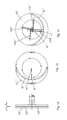
In embodiment 1 as shown in FIGS. 1-2, a pneumatic liquid on-line automatic balancer of a rotor includes a sealed balancing disk 1 and a pressure transfer device 9. The pressure transfer device 9 includes a gas distributor 2, two position three way electromagnetic valves and a gas source. The sealed balancing disk 1 includes a body 11 of the balancing disk and a cover 12 which is fixed in the body 11 of the balancing disk by bolts. A central hole 111 is provided in the body 11 of the balancing disk and a first, a second, a third and a fourth chambers 31, 32, 33, 34 are uniformly formed between the central hole 111 and an outer wall of the body 11 of the balancing disk. The first and the third chambers 31, 33 are formed into one symmetric pair and the second and the fourth chambers 32, 34 are formed into the other symmetric pair. Each the chamber is filled with balancing liquid, whose volume is less than half of each chamber's volume. The balancing liquid can be water, silicone oil, fluorocarbon oil, liquid gallium and the like. As shown in FIG. 3, a first communication tube 41 is provided between the first and the third chambers 31, 33 and a second communication tube 42 is provided between the second and the fourth chambers 32, 34. Centers of the first and the second communication tubes 41, 42 are respectively connected with the first and the second balancing tubes 51, 52. First ends of the first and the second balancing tubes 51, 52 are pointed to a center of rotation and second ends are connected to first ends of a first and a second emptying tubes 61, 62 axially located near the center of rotation. Second ends of the first and the second emptying tubes 61, 62 are opened to atmosphere. The first and the second communication tubes 41, 42 and the first and the second balancing tubes 51, 52 are arranged outside of the sealed balancing disk 1. The first communication tube 41 is the liquid channel between the first and the third chambers 31, 33, the second communication tube 42 is the liquid channel between the second and the fourth chambers 32, 34, and the first and the second balancing tubes 51, 52 form the balancing channel. The gas distributor 2 comprises a central rotor 21, a middle sleeve 22 and an outer stator 23. The outer stator 23 is provided in the central hole 111 in the body of the balancing disk with a space between the outer stator 23 and the body 11 of the balancing disk. The outer stator 23 is annular and an inner wall of the outer stator 23 is provided with the middle sleeve 22 and the central rotor 21 in turn with a gap between the middle sleeve 22 and the central rotor 21. Two bearings are respectively arranged at two ends of the middle sleeve 22 and an outer race and an inner race of the above bearings are tightly fitted with the inner wall of the outer stator 23 and an outer wall of the central rotor 21 respectively. A first, a second, a third and a fourth radial inlet channels 231, 232, 233, 234 are provided in an outer wall of the outer stator 23. The four radial inlet channels are arranged in the outer stator 23 in an axial direction in turn and first ends of a first, a second, a third and a fourth inlet pipes 71, 72, 73, 74 are connected to the first, the second, the third and the fourth radial inlet channels 231, 232, 233, 234, respectively. Four two position three way electromagnetic valves are provided in the first, the second, the third and the fourth inlet pipes 71, 72, 73, 74, respectively. Second ends of the first, the second, the third and the fourth inlet pipes 71, 72, 73, 74 are connected to a gas source. Four axial inlet channels are provided in different radial angle positions of the central rotor 21 and four circumferential gas inlet grooves 211, 212, 213, 214 are provided in the central rotor 21. The gas inlet grooves are circumferential annular grooves provided in the outer wall of the central rotor 21 in turn. One end of each axial inlet channel is respectively communicated with the gas inlet groove through one radial hole and the other end is communicated with one inlet branch 711. In the annular inner walls of the first, the second, the third and the fourth chambers 31, 32, 33, 34 are formed one inlet channel communicated with the chambers, such as the inlet channel 330 in the third chamber 33 as shown in FIG. 3. Each the inlet branch is communicated with the first, the second, the third and the fourth chambers 31, 32, 33, 34 through the inlet channel and connected to the sealed balancing disk 1 through a pipe joint, respectively. In the axial direction, the middle sleeve 22 is provided with four vents 221, 222, 223, 224 in turn, one end of which is communicated with the four gas inlet grooves 211, 212, 213, 214 respectively and the other end of which is communicated with the first, the second, the third and the fourth radial inlet channels 231, 232, 233, 234 respectively. The first and the second emptying tubes 61, 62 have a same structure, as shown in FIG. 1. The first emptying tube 62 includes an axial emptying section 215 and a radial emptying section 216 located in the central rotor 21, a radial emptying section 225 located in the central sleeve 22 and a radial emptying section 235 located in the outer stator 23. The radial emptying section 235 in the outer stator 23 is opened to the atmosphere.
Moreover, there are also five pressure-equalizing grooves 217 in the central rotor 21, which are circumferential annular grooves provided in the outer wall of the central rotor 21, and the five pressure-equalizing grooves and the four gas inlet grooves 211, 212, 213, 214 are alternately distributed.
In use, as shown in FIG. 4, the pneumatic liquid on-line automatic balancer of the rotor is installed at a motorized spindle connecting rod 81 of a drilling machine 8. The motorized spindle connecting rod 81 drives the sealed balancing disk 1 and the central rotor 21 to rotate together. A vibration sensor and a proximity switch are installed on the motorized spindle connecting rod 81. The vibration sensor, the proximity switch and four two position three way electromagnetic valves are connected to an automatic balance controller, and a vibration waveforms signal is transmitted from the vibration sensor to the automatic balance controller. In each rotation of the pneumatic liquid on-line automatic balancer of the rotor according to the present invention, a keyway in the motorized spindle connecting rod 81 would pass over the proximity switch, the proximity switch would output a pulse to the automatic balance controller, a speed of the balanced rotor, an amplitude and phase data of unbalance are extracted from the measured signals of the vibration sensor and the proximity switch by the automatic balance controller, then a transfer object and a transfer quantity of balance control are accordingly calculated and an application time is used as a measure of the transfer quantity. For example, after calculation, the first chamber 31 should be transferred to the third chamber 33 for 2.2 second and the second chamber 32 should be transferred to the fourth chamber 34 for 5.4 second, hence, energization commands for 2.2 seconds and 5.4 seconds are respectively issued to the two position three way electromagnetic valves in the inlet pipes of the first and the second chambers. The compressed gas is leaded to the radial inlet channel in the outer stator 23 through the two position three way electromagnetic valve, to the gas inlet groove in the central rotor 21 through a vent groove in the middle sleeve 22 and the radial communication tube, to the axial inlet channel through the radial hole and to the chamber through the corresponding inlet branch. Under the pressure, the balancing liquid in the first chamber 31 flows to the third chamber 33 through the first communication tube 41 and the balancing liquid in the second chamber 32 flows to the fourth chamber 34 through the second communication tube 42. After 2.2 seconds, the two position three way electromagnetic valve in the inlet pipe of the first chamber is deenergized and the two position three way electromagnetic valve in the inlet pipe of the second chamber is not deenergized till 5.4 seconds. The automatic balancer controller will send the control command of a second cycle in basis of a residual system unbalance at an end of a first control cycle in addition until the vibration falls in an allowable scope, then the balance process will finish. Under the control of the automatic balancer controller, the inlet can be thoroughly cut off and no pressure can be supplied to the chamber, the compressed gas in the chamber would retrace the flow and be emptied from a normally-open port of the two position three way electromagnetic valve.
In embodiment 2 as shown in FIGS. 5-6, a pneumatic liquid on-line automatic balancer of a rotor includes a sealed balancing disk 1′ and a pressure transfer device 9′. The pressure transfer device 9′ includes a gas distributor 2′, two position three way electromagnetic valves and a gas source. The sealed balancing disk 1′ includes a body 11′ of the balancing disk and a cover 12′ which is fixed in the body 11′ of the balancing disk by bolts. The body 11′ of the balancing disk is circular. A first, a second, a third and a fourth chambers 31′, 32′, 33′, 34′ are uniformly formed between a central hole 111′ and an inner wall of the body 11′ of the balancing disk, and the four chambers are sectors. The embodiment 2 differs from embodiment 1 in that the sealed balancing disk 1′ is installed vertically, a volume of balancing liquid in each the chamber is less than the one fourth of each chamber's volume. The gas distributor 2′ comprises a central stator 21′ and a middle sleeve 22′. The central stator 21′ is arranged in the central hole 111′ in the body 11′ of the balancing disk and the middle sleeve 22′ is arranged between the central stator 21′ and the body 11′ of the balancing disk. There is a tight fit between the middle sleeve 22′ and a wall of the central hole 111′ and there is a gap between the middle sleeve and the central stator 21′. Two bearings are respectively arranged at both ends of the middle sleeve 22′. There is a tight fit between an outer race of the bearing and the wall of the central hole 111′ as well as between an inner race of the bearing and the central stator 21′. A first, a second, a third and a fourth axial inlet channels 211′, 212′, 213′, 214′ are provided in the central stator 21′ and four circumferentially distributed annular grooves 215′, 216′, 217′, 218′ are provided in an outer wall of the central stator 21′. First ends of the four axial inlet channels are respectively communicated with the annular groove through a radial vent. A gas injection tube 331′ is provided in an inner walls of the first, the second, the third and the fourth chambers 31′, 32′, 33′, 34′, respectively and in an outer surface of the middle sleeve 22′ is provided with four axial grooves 221′, one end of which is communicated with the gas injection tubes 331′ of the four chambers respectively and the other end of which is communicated with one annular groove in the central stator 21′ through the vent. The vents are provided at the ends of the axial grooves respectively and passed through the middle sleeve 22′. Second ends of the first, the second, the third and the fourth axial inlet channels 211′, 212′, 213′, 214′ are connected to the gas source through a supply pipe, respectively. One of the two position three way electromagnetic valves is provided in each the supply pipe, as shown in FIGS. 7, 8, 9 and 10. A central hole is provided in the cover 12′ and the cover 12′ comprises a left, a right plate 121′, 123′ and a middle plate 122′ welded together by braze welding in turn. A second balancing liquid communication channel 42′ and a second balancing channel 52′ of the second and the fourth chambers are provided in a right side of the left plate 121′, and a first balancing liquid communication channel 41′ and a first balancing channel 51′ of the first and the third chambers are provided in a left side of the right plate. Centers of the first and the second balancing liquid communication channels 41′, 42′ are respectively connected with the first and the second balancing channels 51′, 52′. First ends of the first and the second balancing channels 51′, 52′ are pointed to a center of rotation and second ends thereof are connected to a first and a second emptying channels 61′, 62′ axially located near the center of rotation. The second emptying channel 62′ is opened to the atmosphere through the right plate and the middle plate and the first emptying channel 61′ is opened to the atmosphere through the right plate. There are also five pressure-equalizing grooves in the central stator 21′.
In use, as shown in FIG. 5, the sealed balancing disk 1′ is fixed at a motorized spindle connecting rod 71′ by bolts, then a grinding wheel 72′ is clamped on the sealed balancing disk 1′ by a flange 73′ and fixed by bolts, and the motorized spindle drives the sealed balancing disk 1′ and the grinding wheel 72′ rotate together. A control method is the same as that of the embodiment 1.
In embodiment 3 as shown in FIG. 11, a pneumatic liquid on-line automatic balancer of a rotor includes a sealed balancing disk 1″ and a pressure transfer device 9″. The sealed balancing disk 1″ includes a body 11″ of the balancing disk and an alternative cover 12″ which connected with the body 11″ of the balancing disk by braze welding. The pressure transfer device 9″ includes a gas distributor 2″, two position three way electromagnetic valves and a gas source. The gas distributor 2″ comprises a central rotor 21″, a middle sleeve 22″ and an outer stator 23″. The embodiment 3 differs from embodiment 1 in that the gas distributor 2″ is located axial outside of the sealed balancing disk 1″. The sealed balancing disk 1″ is uniformly divided into a first, a second, a third and a fourth chambers 31″, 32″, 33″, 34″ which are sectors, as shown in FIGS. 12, 13 and 14. The alternative cover 12″ comprises a left, a right and a middle plate 121″, 123″, 122″ welded together by braze welding. The right plate 123″ is integrated with the central rotor 21″, the outer stator 23″ is sleeved on the central rotor 21″ and the middle sleeve 22″ is located between the central rotor 21″ and the outer stator 23″. A second balancing liquid communication channel 42″ and a second balancing channel 52″ of the second and the fourth chambers are provided in a right side of the left plate 121″. In a left side of the right plate 123″ are provided with a first balancing liquid communication channel 41″, a first balancing channel 51″ of the first and the third chambers and four gas injection channels 1231″, 1232″, 1233″, 1234″. First ends of the four gas injection channels are respectively communicated with one axial inlet channel in the central rotor 21″ and second ends of the four injection channels are communicated with the four chambers through gas injection holes provided in the middle and the left plates respectively. Centers of the first and the second communication channels 41″, 42″ are respectively connected with the first and the second balancing channels 51″, 52″. First ends of the first and the second balancing channels 51″, 52″ are pointed to a center of rotation and second ends thereof are connected to a first and a second emptying vents 61″, 62″ axially located near the center of rotation. A first and a second axial extending emptying tubes are provided in the central rotor 21″. Ends of the first and the second emptying tubes are both provided with a gas-permeable and anti-liquid plug, that is, the first emptying tube 211″ and the gas-permeable and anti-liquid plug 212″ at the end thereof shown in FIG. 11. The first vent 61″ is communicated with the first emptying tube through the right plate and the second vent 62″ is communicated with the second emptying tube through the right and the middle plates. The first vent 61″ and the first emptying tube form the first emptying channel and the second vent 62″ and the second emptying tube form the second emptying channel, and the first and the second communication channels 41″, 42″ may be Venturi necking channels. There are also five pressure-equalizing grooves in the central stator 21″.
As shown in FIGS. 15-18, an alternative cover 12″ can be made into four layers to simplify machining process of the groove or the hole in the cover with a small diameter. The alternative cover 12″ includes a left plate 121″, a middle plate 122″, a first right plate 123″ and a second right plate 124″, four gas injection channels are positioned in a right side of the left plate 121″, the first communication channel 41″ is positioned in a left side of the first right plate 123″, the second communication channel 42″ is positioned in a left side of the second right plate 124″, and the first and the second communication channels 41″, 42″ may be Venturi channels.
Moreover, as shown in FIG. 11, the arc outer wall of the chamber is a conical surface outward leaned in an axial direction. The connections between the first communication channel 41″ and the first and the third chambers 31″, 33″ are respectively notched in the grooves 311″, 331″ in the arc outer walls of the first and the third chambers, and the connections between the second communication channel 42″ and the second and the fourth chambers 32″, 34″ are respectively notched in the grooves in the arc outer walls of the second and the fourth chambers.
The embodiments described above only describe the preferred embodiments of the present invention and are not intended to limit the present invention. Various changes and modifications to the embodiments of the present invention made by those skilled in the art may fall in the scope as defined by the appended claims without departing the design spirit of the present invention.
Industrial Application
The pneumatic liquid on-line automatic balancer of the rotor according to the present invention can be used in various rotating devices, especially in a high-speed rotating device, improving the balance level of the high-speed rotating device, reducing the vibration, being of compact structure, permanent balance ability and industrial applicability.

Claims (13)

What is claimed is:
1. A pneumatic liquid on-line automatic balancer of a rotor, comprising a sealed balancing disk (1) rotating with a balanced rotor about a central axis and a pressure transfer device (9) mated with the sealed balancing disk (1), wherein at least two pairs of centrosymmetric chambers (31, 32, 33, 34) filled with appropriate balancing liquid are evenly distributed in the sealed balancing disk, the pressure transfer device controls compressed gas in and out of a chamber and makes the balancing liquid controllably flow in each pair of the chambers to achieve dynamic balance of the rotor, a communicating channel of the balancing liquid is provided between outer edges of each pair of the chambers, a quantity of the communicating channel of the balancing liquid is one, a center of the communicating channel of the balancing liquid is communicated with a balancing channel pointed to a center of rotation, the balancing channel is communicated with an end of an emptying channel axially located near the center of rotation, and the other end of the emptying channel is opened to atmosphere;
wherein, the chambers in the sealed balancing disk (1) are two pairs, the first and the third chambers (31, 33) are formed into one pair in which the communicating channel of the balancing liquid is a first communicating tube (41), and the second and the fourth chambers (32, 34) are formed into one pair in which the communicating channel of the balancing liquid is a second communicating tube (42), the balancing channels are respectively a first and a second balancing tubes (51, 52) and emptying channels are respectively a first and a second emptying tubes (61, 62).
2. The pneumatic liquid on-line automatic balancer of the rotor of claim 1, wherein, the pressure transfer device (9) comprises a gas distributor (2) and two position three way electromagnetic valves, the gas distributor (2) comprises a central rotor (21), a middle sleeve (22) and an outer stator (23), the outer stator (23) is provided in a body (11) of the balancing disk with a space between the outer stator (23) and the body (11) of the balancing disk, an inner wall of the outer stator (23) is provided with the middle sleeve (22) and the central rotor (21) in turn with a gap between the middle sleeve (22) and the central rotor (21), two bearings are respectively arranged at ends of the middle sleeve (22) and an outer race and an inner race of the above bearing is tightly fitted with the inner wall of the outer stator (23) and an outer wall of the central rotor (21), respectively, a first, a second, a third and a fourth radial inlet channels (231, 232, 233, 234) are provided in an outer wall of the outer stator (23), the four radial inlet channels are arranged in the outer stator (23) in an axial direction in turn and a first, a second, a third and a fourth inlet pipes (71, 72, 73, 74) are connected to the first, the second, the third and the fourth radial inlet channels (231, 232, 233, 234), respectively, one of the two position three way electromagnetic valve is provided in the first, the second, the third and the fourth inlet pipes (71, 72, 73, 74), respectively, four axial inlet channels are provided in different radial positions of the central rotor (21) and four circumferential gas inlet grooves (211, 212, 213, 214) are provided in the outer wall of the central rotor (21), one end of each the axial inlet channel is respectively communicated with each of the circumferential gas inlet grooves (211, 212, 213, 214) through one radial hole and the other end is communicated with a corresponding inlet branch (711), in annular inner walls of the four chambers are formed one inlet channel through which the branch is communicated with the corresponding chamber, respectively, the inlet branch is connected to the body (11) of the sealed balancing disk, the middle sleeve (22) is provided with four vents (221, 222, 223, 224) in turn, one end of which is communicated with the four circumferential gas inlet grooves (211, 212, 213, 214) respectively and the other end of which is communicated with the first, the second, the third and the fourth radial inlet channels (231, 232, 233, 234) respectively.
3. The pneumatic liquid on-line automatic balancer of the rotor of claim 2, wherein, the first and the second emptying tubes (61, 62) have a same structure, the first emptying tube (62) comprises an axial emptying section (215) and a first radial emptying section (216) located in the central rotor (21), a second radial emptying section (225) located in the central sleeve (22) and a third radial emptying section (235) located in the outer stator (23), the third radial emptying section (235) in the outer stator (23) is opened to the atmosphere.
4. The pneumatic liquid on-line automatic balancer of the rotor of claim 3, wherein, there are also five pressure-equalizing grooves (217) in the central rotor (21), which are circumferential annular grooves provided in the outer wall of the central rotor (21), and the five pressure-equalizing grooves and the four gas inlet grooves (211, 212, 213, 214) are alternately distributed.
5. The pneumatic liquid on-line automatic balancer of the rotor of claim 1, wherein, the sealed balancing disk (1′) comprises a body (11′) of the balancing disk and a cover (12′) which is hermetically fixed with the body (11′) of the balancing disk, the chambers are formed into two pairs, comprising a first, a second, a third and a fourth chambers (31′, 32′, 33′, 34′), the first and the third chambers are formed into one pair and the second and the fourth chambers are formed into the other pair, the pressure transfer device (9′) comprises a gas distributor (2′) and two position three way electromagnetic valves which are communicated in turn, the gas distributor (2′) comprises a central stator (21′) and a middle sleeve (22′), the central stator (21′) is arranged in the central hole (111′) in the body (11′) of the balancing disk and the middle sleeve (22′) is arranged between the central stator (21′) and the body (11′) of the balancing disk, there is a tight fit between the middle sleeve (22′) and a wall of the central hole (111′) and there is a gap between the middle sleeve and the central stator (21′), two bearings are respectively arranged at both ends of the middle sleeve (22′), there is a tight fit between an outer race of the bearing and the wall of the central hole (111′) as well as between an inner race of the bearing and the central stator (21′), a first, a second, a third and a fourth axial inlet channels (211′, 212′, 213′, 214′) are provided in the central stator (21′) and four circumferentially distributed annular grooves (215′, 216′, 217′, 218′) are provided in an outer wall of the central stator (21′), a first end of each of the four axial inlet channels is respectively communicated with the annular groove through a radial vent, a gas injection tube (331′) is provided in inner walls of the four chambers, respectively, in an outer surface of the middle sleeve (22′) is provided with four axial grooves (221′), one end of which is communicated with the gas injection tubes of the four chambers respectively and the other end of which is communicated with the annular groove in the central stator (21′) through the vent, the vents are provided at the ends of the axial grooves respectively and passed through the middle sleeve (22′), gas is inputted to second ends of the first, the second, the third and the fourth axial inlet channels (211′, 212′, 213′, 214′) through a supply pipe, respectively, one of the two position three way electromagnetic valves is provided in each the supply pipe, a central hole is provided in the cover (12′) and the cover (12′) comprises a left, a right plate (121′, 123′) and a middle plate (122′) fixed together in turn, a second balancing liquid communication channel (42′) and a second balancing channel (52′) of the second and the fourth chambers are provided in a right side of the left plate (121′) and a first balancing liquid communication channel (41′) and a first balancing channel (51′) of the first and the third chambers are provided in a left side of the right plate (123′), centers of the first and the second balancing liquid communication channels (41′, 42′) are respectively connected with first ends of the first and the second balancing channels (51′, 52′), the cover (12′) is also provided with a first and a second emptying channels (61′, 62′), the second emptying channel (62′) is opened to the atmosphere through the right plate and the middle plate and the first emptying channel (61′) is opened to the atmosphere through the right plate, second ends of the first and the second balancing channels (51′, 52′) are connected to the first and the second emptying channels (61′, 62′).
6. The pneumatic liquid on-line automatic balancer of the rotor of claim 5, wherein, there are also five pressure-equalizing grooves in the central stator (21′) which are circumferential annular grooves provided in the outer wall of the central stator (21′), the five pressure-equalizing grooves and annular grooves (215′, 216′, 217′, 218′) are alternately distributed, and the pressure-equalizing grooves are communicated with five pressure relief holes provided in the middle sleeve (22′).
7. The pneumatic liquid on-line automatic balancer of the rotor of claim 1, wherein, the sealed balancing disk (1″) comprises a body (11″) of the balancing disk and an alternative cover (12″) fixed by each other, the pressure transfer device (9″) comprises a gas distributor (2″) and two position three way electromagnetic valves which are communicated in turn, the gas distributor (2″) is located at an axial outside of the sealed balancing disk (1″) and comprises a central rotor (21″), a middle sleeve (22″) and an outer stator (23″), the outer stator (23″) is sleeved on the central rotor (21″) and the middle sleeve (22″) is located between the central rotor (21″) and the outer stator (23″), four axial inlet channels are provided in the central rotor (21″) and a first, a second, a third and a fourth chambers (32″, 32″, 33″, 34″) are provided in the body (11″) of the balancing disk, in which the first and the third chambers are formed into one pair and the second and the fourth chambers are formed into the other pair, the alternative cover (12″) is made into three layers and comprises a left plate (121″), a right plate (123″) and a middle plate (122″) hermetically sealed by each other, the right plate (123″) is integrated with the central rotor (21″), the balancing liquid communication channel between the second and the fourth chambers is the second communication channel (42″) in a right side of the left plate (121″) and the balancing liquid communication channel between the first and the third chambers is the first communication channel (41″) in a left side of the right plate (123″), the balancing channels are the second balancing channel (52″) in the right side of the left plate (121″) and the first balancing channel (51″) in the left side of the right plate (123″), in the left side of the right plate (123″) are provided with four gas injection channels (1231″, 1232″, 1233″, 1234″), one end of which is respectively communicated with one axial inlet channel in the central rotor (21″) and the other end of which is communicated with the four chambers respectively, centers of the first and the second communication channels (41″, 42″) are respectively connected with first ends of the first and the second balancing channels (51″, 52″), second ends of the first and the second balancing channels (51″, 52″) are connected to a first and a second vents (61″, 62″) respectively, a first and a second axial extending emptying tubes are provided in the central rotor (21″), the first vent (61″) is communicated with the first emptying tube through the right plate and the second vent (62″) is communicated with the second emptying tube through the right and the middle plate, the first vent (61″) and the first emptying tube form the first emptying channel and the second vent (62″) and the second emptying tube form the second emptying channel, and the first and the second communication channels (41″, 42″) are Venturi necking channels.
8. The pneumatic liquid on-line automatic balancer of the rotor of claim 7, wherein, the ends of the first and the second emptying tube are both provided with an air-permeable and anti-liquid plug.
9. The pneumatic liquid on-line automatic balancer of the rotor of claim 8, wherein, the first, the second, the third and the fourth chambers (31″, 32″, 33″, 34″) are sectors.
10. The pneumatic liquid on-line automatic balancer of the rotor of claim 9, wherein, the arc outer wall of each the chamber is a conical surface outward leaned in an axial direction.
11. The pneumatic liquid on-line automatic balancer of the rotor of claim 10, wherein, connections between the first communication channel (41″) and the first and the third chambers (31″, 33″) are respectively notched in grooves (311″, 331″) in the arc outer walls of the first and the third chambers, and the connections between the second communication channel (42″) and the second and the fourth chambers (32″, 34″) are respectively notched in the grooves in the arc outer walls of the second and the fourth chambers.
12. The pneumatic liquid on-line automatic balancer of the rotor of claim 11, wherein, the alternative cover (12″) is made into four layers instead of the three-layer cover and comprises a left plate (121″), a middle plate (122″), a first right plate (123″) and a second right plate (124″), four gas injection channels are positioned in a right side of the left plate (121″), the first communication channel (41″) is positioned in a left side of the first right plate (123″), the second communication channel (42″) is positioned in a left side of the second right plate (124″), and the first and the second communication channels (41″, 42″) are Venturi necking channels.
13. The pneumatic liquid on-line automatic balancer of the rotor of claim 12, wherein, there are also five pressure-equalizing grooves (217) in the central rotor (21), which are circumferential annular grooves provided in the outer wall of the central rotor (21), and the five pressure-equalizing grooves and the four gas inlet grooves (211, 212, 213, 214) are alternately distributed.
US14/370,049 2011-12-30 2012-12-28 Pneumatic liquid on-line automatic balancer of rotor Expired - Fee Related US9212723B2 (en)

Applications Claiming Priority (4)

Application Number Priority Date Filing Date Title
CN201110457792.1 2011-12-30
CN201110457792 2011-12-30
CN201110457792.1A CN102840949B (en) 2011-12-30 2011-12-30 Pneumatic liquid type rotor online automatic balance executer
PCT/CN2012/001777 WO2013097301A1 (en) 2011-12-30 2012-12-28 Online automatic balancer for air pressure liquid-type rotor

Publications (2)

Publication Number Publication Date
US20140311281A1 US20140311281A1 (en) 2014-10-23
US9212723B2 true US9212723B2 (en) 2015-12-15

Family

ID=47368514

Family Applications (1)

Application Number Title Priority Date Filing Date
US14/370,049 Expired - Fee Related US9212723B2 (en) 2011-12-30 2012-12-28 Pneumatic liquid on-line automatic balancer of rotor

Country Status (4)

Country Link
US (1) US9212723B2 (en)
EP (1) EP2799831B1 (en)
CN (2) CN102840949B (en)
WO (1) WO2013097301A1 (en)

Cited By (1)

* Cited by examiner, † Cited by third party
Publication number Priority date Publication date Assignee Title
US11092944B2 (en) * 2018-01-09 2021-08-17 Xi'an Jiaotong University Integrated 3D-prototyped online dynamic balance terminal

Families Citing this family (23)

* Cited by examiner, † Cited by third party
Publication number Priority date Publication date Assignee Title
CN102840949B (en) * 2011-12-30 2015-04-01 北京博华信智科技股份有限公司 Pneumatic liquid type rotor online automatic balance executer
CN103148164B (en) * 2013-03-05 2015-03-11 北京化工大学 Target control method and control system of liquid-type on-line autobalance device
CN103759892A (en) * 2014-01-27 2014-04-30 杭州集智机电股份有限公司 Soft supporting balance test machine with oil mixing damping mechanisms
EP2975006A1 (en) * 2014-07-14 2016-01-20 Rockwool International A/S A centrifugal fiberising spinner unit and a method of automatically balancing such unit
CN104191005B (en) * 2014-07-31 2016-06-22 湖南大学 A kind of milling attachment suitable in high-speed plane finish-milling
CN104807595A (en) * 2015-04-02 2015-07-29 哈尔滨东安发动机(集团)有限公司 Complete dynamic balancing tool for cantilever rotor
CN104948627B (en) * 2015-04-29 2017-04-05 北京交通大学 A kind of single order law of buoyancy magnetic fluid damper with magnetism shielding hood
CN105127888B (en) * 2015-07-10 2017-10-20 西安交通大学 A kind of liquid injection formula on-line dynamic balancing header structure being used under high speed conditions
CN106090120B (en) * 2016-07-01 2018-09-07 北京化工大学 Pneumatic liquid transfer type active balancing system for being installed in axis
CN109026676A (en) * 2016-12-21 2018-12-18 黄山赛德工业泵有限公司 Quimby pump is used in a kind of conveying of self-balancing
CN106768642B (en) * 2016-12-30 2019-01-04 北京化工大学 A kind of dissection type automatic balancing arrangement for realizing rotating machinery on line auto balancing
CN108168779A (en) * 2017-12-11 2018-06-15 西北机电工程研究所 A kind of design method of gas liquid type balancing machine
CN108168780A (en) * 2017-12-11 2018-06-15 西北机电工程研究所 A kind of gas liquid type balancing machine
CN107956840B (en) * 2017-12-26 2024-08-16 中国工程物理研究院总体工程研究所 Electromagnetic automatic balancing head
CN110864077B (en) * 2019-10-12 2021-03-26 北京化工大学 A motor-driven automatic balancing system with autonomous control capability
CN111451840B (en) * 2020-04-08 2021-11-30 秦皇岛齐二数控机床有限公司 High-speed self-balancing rotary table
CN111843525B (en) * 2020-07-06 2021-06-22 珠海格力电器股份有限公司 Rotor assembly, electric spindle and motor
CN111686948A (en) * 2020-07-08 2020-09-22 中国工程物理研究院总体工程研究所 Dynamic unbalance force adjusting system and geotechnical centrifuge
CN112378581B (en) * 2020-12-11 2024-12-03 长春工业大学 A dynamic balancing device for grinding wheel
CN114184723B (en) * 2021-12-30 2025-02-18 泰渡生物科技(苏州)有限公司 Rotary valve, sample loading device and chromatography experiment system
CN115355282A (en) * 2022-02-24 2022-11-18 北京化工大学 Hydraulic type large-diameter automatic balance actuator
CN114453959B (en) * 2022-03-23 2022-12-20 日照职业技术学院 Main shaft vibration reduction automatic control system for eccentric cambered surface cam machining
CN116885890B (en) * 2023-09-07 2023-11-21 常州市昊升电机股份有限公司 Efficient durable brushless motor and working method thereof

Citations (10)

* Cited by examiner, † Cited by third party
Publication number Priority date Publication date Assignee Title
US2659243A (en) * 1951-07-05 1953-11-17 Bbc Brown Boveri & Cie Apparatus for automatic balancing of rotating bodies
US3950897A (en) * 1973-11-19 1976-04-20 Gebr. Hofmann Kg Multi-chambered fluid balancing apparatus
US4002086A (en) * 1972-06-06 1977-01-11 Rolf Bertil Reinhall Device for automatic correction of unbalance in rapidly rotating machine elements
GB2080836A (en) 1980-06-09 1982-02-10 Mitsubishi Heavy Ind Ltd Dry cleaning machine
US4537177A (en) * 1982-05-07 1985-08-27 Silicon Technology Balanced rotary saw assembly and a method of balancing the same
CN1358942A (en) 2001-07-06 2002-07-17 王文杰 Dynamic balance device
WO2004010022A2 (en) 2002-07-19 2004-01-29 Ultra Electronics Limited Adaptive balancing arrangement for a rotating mass and a method of operating such an arrangement
CN1647766A (en) 2004-01-28 2005-08-03 西门子公司 Imaging tomography equipment
CN102183338A (en) 2011-01-18 2011-09-14 西安交通大学 Liquid-injection type online dynamic balance head structure for high rotating speed
CN102840949A (en) 2011-12-30 2012-12-26 北京博华信智科技发展有限公司 Pneumatic liquid type rotor online automatic balance executer

Family Cites Families (4)

* Cited by examiner, † Cited by third party
Publication number Priority date Publication date Assignee Title
US4432253A (en) * 1981-04-20 1984-02-21 Balance Dynamics Co. Unbalance compensator
IT1319748B1 (en) * 2000-12-22 2003-11-03 Balance Systems Spa DEVICE FOR BALANCING A ROTATING BODY, IN PARTICULAR A HIGH SPEED ROTATING TOOL HOLDER.
CN100346089C (en) * 2005-03-09 2007-10-31 北京化工大学 Liquid type rotor on-line automatic balance head
CN202083521U (en) * 2011-03-28 2011-12-21 中国计量学院 Liquid type high speed rotor online dynamic balancing head

Patent Citations (10)

* Cited by examiner, † Cited by third party
Publication number Priority date Publication date Assignee Title
US2659243A (en) * 1951-07-05 1953-11-17 Bbc Brown Boveri & Cie Apparatus for automatic balancing of rotating bodies
US4002086A (en) * 1972-06-06 1977-01-11 Rolf Bertil Reinhall Device for automatic correction of unbalance in rapidly rotating machine elements
US3950897A (en) * 1973-11-19 1976-04-20 Gebr. Hofmann Kg Multi-chambered fluid balancing apparatus
GB2080836A (en) 1980-06-09 1982-02-10 Mitsubishi Heavy Ind Ltd Dry cleaning machine
US4537177A (en) * 1982-05-07 1985-08-27 Silicon Technology Balanced rotary saw assembly and a method of balancing the same
CN1358942A (en) 2001-07-06 2002-07-17 王文杰 Dynamic balance device
WO2004010022A2 (en) 2002-07-19 2004-01-29 Ultra Electronics Limited Adaptive balancing arrangement for a rotating mass and a method of operating such an arrangement
CN1647766A (en) 2004-01-28 2005-08-03 西门子公司 Imaging tomography equipment
CN102183338A (en) 2011-01-18 2011-09-14 西安交通大学 Liquid-injection type online dynamic balance head structure for high rotating speed
CN102840949A (en) 2011-12-30 2012-12-26 北京博华信智科技发展有限公司 Pneumatic liquid type rotor online automatic balance executer

Cited By (1)

* Cited by examiner, † Cited by third party
Publication number Priority date Publication date Assignee Title
US11092944B2 (en) * 2018-01-09 2021-08-17 Xi'an Jiaotong University Integrated 3D-prototyped online dynamic balance terminal

Also Published As

Publication number Publication date
CN102840949B (en) 2015-04-01
EP2799831A1 (en) 2014-11-05
WO2013097301A1 (en) 2013-07-04
EP2799831A4 (en) 2015-12-02
CN103874868B (en) 2016-10-19
CN102840949A (en) 2012-12-26
US20140311281A1 (en) 2014-10-23
EP2799831B1 (en) 2017-03-15
CN103874868A (en) 2014-06-18

Similar Documents

Publication Publication Date Title
US9212723B2 (en) Pneumatic liquid on-line automatic balancer of rotor
WO2014200170A1 (en) Bearing variable preload system utilizing gap between strokes for preload adjustment and elastic deformation of sealing member
CN102179532A (en) Ultrahigh-precision aerostatic bearing main shaft system
JP6081818B2 (en) Rotary table device
CN106704172B (en) A self-balancing device and a twin-screw pump for pressurized delivery
CN107363720A (en) Suitable for the liquid-spraying type on-line dynamic balancing terminal of big external diameter external thread grinder main shaft
CN101204779A (en) Ring-shaped lead rail of vertical type lathe
CN113210641B (en) Dynamic precision adjusting device for electric spindle of high-speed machine tool
CN209969691U (en) Swinging head structure on double-swinging milling head
CN103620282B (en) Rotary distribution device
CN117268631A (en) Online dynamic balance device and dynamic balance method for liquid type rotor
CN109341973B (en) Three-way valve and internal and external leakage detection conversion device
CN109245489A (en) A kind of hydraulic feedback permanent magnet speed regulation device
CN210387604U (en) A kind of gas static pressure main shaft gas film stepless variable damping device
WO2023160334A1 (en) Liquid-pressing-type automatic balance actuator with large diameter
US2849013A (en) Multiple jet pipe relay regulator
CN102963744B (en) Coiler with variable support stiffness
CN106090120B (en) Pneumatic liquid transfer type active balancing system for being installed in axis
CN102305028B (en) High-tightness high pressure-resistant double-guide faucet
CN209469912U (en) A kind of air bearing rotary joint
CN110193611B (en) Electric spindle structure of hybrid supporting self-balancing machine tool and control method thereof
CN210262371U (en) Device for automatically adjusting balance liquid
CN210290310U (en) Rotary pressure servo valve
CN108194385A (en) Two phase flow fluid machinery flow passage components polishing machine test device and test method
CN204052940U (en) A kind of the Aerostatic Spindle with turn error monitoring function

Legal Events

Date Code Title Description
STCF Information on status: patent grant

Free format text: PATENTED CASE

MAFP Maintenance fee payment

Free format text: PAYMENT OF MAINTENANCE FEE, 4TH YR, SMALL ENTITY (ORIGINAL EVENT CODE: M2551); ENTITY STATUS OF PATENT OWNER: SMALL ENTITY

Year of fee payment: 4

FEPP Fee payment procedure

Free format text: MAINTENANCE FEE REMINDER MAILED (ORIGINAL EVENT CODE: REM.); ENTITY STATUS OF PATENT OWNER: SMALL ENTITY

LAPS Lapse for failure to pay maintenance fees

Free format text: PATENT EXPIRED FOR FAILURE TO PAY MAINTENANCE FEES (ORIGINAL EVENT CODE: EXP.); ENTITY STATUS OF PATENT OWNER: SMALL ENTITY

STCH Information on status: patent discontinuation

Free format text: PATENT EXPIRED DUE TO NONPAYMENT OF MAINTENANCE FEES UNDER 37 CFR 1.362

FP Lapsed due to failure to pay maintenance fee

Effective date: 20231215