US9210998B2 - Table system for serving and displaying food and beverages - Google Patents
Table system for serving and displaying food and beverages Download PDFInfo
- Publication number
- US9210998B2 US9210998B2 US13/481,846 US201213481846A US9210998B2 US 9210998 B2 US9210998 B2 US 9210998B2 US 201213481846 A US201213481846 A US 201213481846A US 9210998 B2 US9210998 B2 US 9210998B2
- Authority
- US
- United States
- Prior art keywords
- ring
- ring shaped
- shaped plates
- serving
- shaft
- Prior art date
- Legal status (The legal status is an assumption and is not a legal conclusion. Google has not performed a legal analysis and makes no representation as to the accuracy of the status listed.)
- Active, expires
Links
- 235000013361 beverage Nutrition 0.000 title description 4
- 235000013305 food Nutrition 0.000 title description 4
- 235000021170 buffet Nutrition 0.000 description 2
- 239000003086 colorant Substances 0.000 description 1
- 239000003517 fume Substances 0.000 description 1
- 239000000463 material Substances 0.000 description 1
- 238000000034 method Methods 0.000 description 1
- 238000006748 scratching Methods 0.000 description 1
- 230000002393 scratching effect Effects 0.000 description 1
- 230000007704 transition Effects 0.000 description 1
Images


Classifications
-
- A—HUMAN NECESSITIES
- A47—FURNITURE; DOMESTIC ARTICLES OR APPLIANCES; COFFEE MILLS; SPICE MILLS; SUCTION CLEANERS IN GENERAL
- A47B—TABLES; DESKS; OFFICE FURNITURE; CABINETS; DRAWERS; GENERAL DETAILS OF FURNITURE
- A47B13/00—Details of tables or desks
- A47B13/08—Table tops; Rims therefor
- A47B13/088—Sectional table tops
-
- A—HUMAN NECESSITIES
- A47—FURNITURE; DOMESTIC ARTICLES OR APPLIANCES; COFFEE MILLS; SPICE MILLS; SUCTION CLEANERS IN GENERAL
- A47B—TABLES; DESKS; OFFICE FURNITURE; CABINETS; DRAWERS; GENERAL DETAILS OF FURNITURE
- A47B47/00—Cabinets, racks or shelf units, characterised by features related to dismountability or building-up from elements
- A47B47/04—Cabinets, racks or shelf units, characterised by features related to dismountability or building-up from elements made mainly of wood or plastics
- A47B47/05—Cabinets, racks or shelf units, characterised by features related to dismountability or building-up from elements made mainly of wood or plastics with panels on a separate frame, e.g. a metal frame
-
- A—HUMAN NECESSITIES
- A47—FURNITURE; DOMESTIC ARTICLES OR APPLIANCES; COFFEE MILLS; SPICE MILLS; SUCTION CLEANERS IN GENERAL
- A47B—TABLES; DESKS; OFFICE FURNITURE; CABINETS; DRAWERS; GENERAL DETAILS OF FURNITURE
- A47B87/00—Sectional furniture, i.e. combinations of complete furniture units, e.g. assemblies of furniture units of the same kind such as linkable cabinets, tables, racks or shelf units
- A47B87/02—Sectional furniture, i.e. combinations of complete furniture units, e.g. assemblies of furniture units of the same kind such as linkable cabinets, tables, racks or shelf units stackable ; stackable and linkable
- A47B87/0207—Stackable racks, trays or shelf units
- A47B87/0215—Stackable frames, or frame elements, with upright parts connected by inserting the ends or tips of the uprights, e.g. at the corners, into the uprights of the next frame or frame element, e.g. coaxial tubular ends
-
- F—MECHANICAL ENGINEERING; LIGHTING; HEATING; WEAPONS; BLASTING
- F16—ENGINEERING ELEMENTS AND UNITS; GENERAL MEASURES FOR PRODUCING AND MAINTAINING EFFECTIVE FUNCTIONING OF MACHINES OR INSTALLATIONS; THERMAL INSULATION IN GENERAL
- F16B—DEVICES FOR FASTENING OR SECURING CONSTRUCTIONAL ELEMENTS OR MACHINE PARTS TOGETHER, e.g. NAILS, BOLTS, CIRCLIPS, CLAMPS, CLIPS OR WEDGES; JOINTS OR JOINTING
- F16B5/00—Joining sheets or plates, e.g. panels, to one another or to strips or bars parallel to them
- F16B5/06—Joining sheets or plates, e.g. panels, to one another or to strips or bars parallel to them by means of clamps or clips
- F16B5/0607—Joining sheets or plates, e.g. panels, to one another or to strips or bars parallel to them by means of clamps or clips joining sheets or plates to each other
- F16B5/0621—Joining sheets or plates, e.g. panels, to one another or to strips or bars parallel to them by means of clamps or clips joining sheets or plates to each other in parallel relationship
- F16B5/065—Joining sheets or plates, e.g. panels, to one another or to strips or bars parallel to them by means of clamps or clips joining sheets or plates to each other in parallel relationship the plates being one on top of the other and distanced from each other, e.g. by using protrusions to keep contact and distance
-
- Y10T403/56—
Definitions
- the present invention refers to a table for serving and displaying food and beverages.
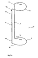
- FIG. 1 depicts a ring-shaped serving table ( 1 ).
- FIG. 2 depicts an S-shaped serving table ( 1 ).
- FIG. 3 depicts a three-tier ring-shaped serving table ( 1 ).
- FIG. 4 depicts a three-tier S-shaped serving table ( 1 ).
- FIG. 5 presents a cross-section of the leg ( 41 ).
- FIG. 6 presents a cross-section of the attaching system ( 6 ).
- FIG. 7 presents a cross-section of the top screw ( 43 ).
- FIG. 8 depicts half of a two-tier ring-shaped table ( 1 ).
- FIG. 9 depicts half of a three-tier ring-shaped table ( 1 ).
- FIGS. 10 and 11 depict combinations involving two halves of a three-tier S-shaped serving table ( 1 ) and a three-tier rectangular extension table ( 5 ).
- FIG. 12 illustrates in cross-section how three table surfaces ( 1 ) are connected by a leg ( 41 ), two support shafts ( 42 ) and one extension shaft ( 61 ).
- FIG. 13 presents the upper tier whereby a connector shaft ( 9 ) is inserted into the extension shaft ( 61 ).
- FIGS. 14 and 15 present two possible cross-sections of the holes ( 7 ) that are symmetrical relative to the holes' lateral axis.
- FIG. 16 depicts the spring ( 90 ).
- FIG. 17 depicts the spring ( 90 ) with a curtain ( 100 ) wrapped around it.
- FIG. 18 depicts the curtain ( 100 ), whereby one end of the curtain ( 100 ) is attached to a spring ( 90 ) and the curtain is in open position.
- FIG. 19 depicts a curtain ( 100 ) in open position that is attached to a pair of springs ( 90 ) that are fit over legs (not shown in the drawing).
- FIG. 20 depicts a two-tier rectangular table ( 5 ) whereby the space between the tiers is closed by a curtain ( 100 ).
- the main objective of the present invention is to provide a ring-shaped serving table ( 1 ) that is made up of two identical or similar half-ring shaped plates ( 2 ) ( 3 ) that can be connected in one of two ways: (a) to form an almost complete ring, with a relatively large, round space in the middle and an entry into that space, as depicted in Drawing No. 1 and (b) to form an S-shaped table as depicted in Drawing No. 2.
- a second objective of the present invention is to provide a ring-shaped serving table ( 1 ), as described above, that has two or more tiers, each of which comprise a plates ( 2 ) ( 3 ), as mentioned, that are assembled using a leg system ( 4 ).
- a third objective of the present invention is to provide a rectangular extension table ( 5 ) with a leg system ( 4 ) that is identical or similar to the leg system ( 4 ) used for the ring-shaped serving table ( 1 ).
- a fourth objective of the present invention is to provide an attaching system ( 6 ) designed to attach accessories to the ring-shaped serving table ( 1 ) and to the rectangular extension table ( 5 ).
- the ring-shaped serving table ( 1 ) comprises two identical or similar half-ring shaped plates ( 2 ) ( 3 ) that when joined together to create an almost complete ring, with a relatively large space in the center and an entry into that space, form the shape described in Drawing No. 1.
- these half-ring shaped plates ( 2 ) ( 3 ) are separable. But first, as shown in Drawing No. 2 it is clear that each of said half-ring shaped plates ( 2 ) ( 3 ) comprises: an outside arc ( 111 ), an inside arc ( 110 ) and two sides (X 1 ) (X 2 ).
- Drawing No. 1 depicts the ring-shaped table ( 1 ) that is created when the flat sides of two half-ring shaped plates ( 2 ) ( 3 ) marked X 1 are placed joined.
- the round space in the middle of the table ( 1 ) is intended as standing room for a waiter serving at the said table and the opening in the ring enables the waiter to access that space.
- the space in the middle of the ring-shaped table ( 1 ) is slightly elliptical and is not a perfect circle, such that the sides marked X 2 are the same length as sides X 1 and are parallel to them. This also enables the user to join the two half-ring shaped plates ( 2 ) ( 3 ) in the way depicted in Drawing No. 2 so that the interface and transition between the two plates is smooth and aesthetic.
- ring-shaped serving table ( 1 ) offers a considerable advantage in that it may be efficiently and aesthetically assembled in two ways, as described above.
- the ring-shaped table ( 1 ) comprises two or more identical or similar tiers, made up of the same plates ( 2 ) ( 3 ), which are assembled as depicted in Drawings Nos. 3 and 4.
- the plates ( 2 ) ( 3 ) are assembled using a leg system ( 4 ) that comprises a leg ( 41 ), a support shaft ( 42 ) and a top screw ( 43 ).
- the half-ring shaped plates ( 2 ) ( 3 ) in the second embodiment of the invention have several holes ( 7 ) that enable the user to assemble the said half-ring shaped plates using the leg system ( 4 ).
- the leg ( 41 ) is a short shaft with a hole ( 411 ) in its upper end, which has an internal thread, as depicted in Drawing No. 5.
- the support shaft ( 42 ) is a shaft with a pin ( 421 ) protruding from its bottom end, which has an external thread, and a hole ( 422 ) in its upper end, which has an internal thread.
- the top screw ( 43 ) is a flat disc with a pin ( 431 ) protruding from its bottom end, which has an external thread, as depicted in Drawing No. 7.
- the plates are assembled as follows to create the table ( 1 ), this description refers to half a table but is the same for the half: First, the pins ( 421 ) protruding from the bottom ends of the support shafts ( 42 ) are screwed, from above, into the holes ( 7 ) in the bottom plate ( 2 ), and the legs ( 41 ) are then screwed, from below, onto the pins ( 421 ) that protrude through the holes.
- a second plate ( 2 ) is placed on the support shafts ( 42 ) that are already in place and the pins ( 431 ) protruding from the bottom of the top screws ( 43 ) are screwed, through the holes ( 7 ) in the second plate ( 2 ), into the holes ( 422 ) in the upper end of the support shafts ( 42 ).
- the two-tier serving table ( 1 ) is now assembled and ready for use, as depicted in Drawing No. 8.
- Drawing No. 9 depicts a three-tier serving table ( 1 ).
- ring-shaped serving table ( 1 ) offers a considerable advantage in that it can be stored without taking up too much space, it can be transported relatively easily, and it can be assembled quickly, efficiently and easily.
- Another advantage is the fact that the same identical plates ( 2 ) ( 3 ) are used for all tiers of the table ( 1 ) and the plates need not be matched according to their position in the table and the legs, support shafts and top screws are uniform and there is no need to mark them or match them to specific holes in the said plates.
- the ring-shaped table in the third embodiment of the invention includes a leg system and rectangular plates that are assembled, as described above, to form a rectangular extension table ( 5 ) that may then be joined to the ring-shaped table ( 1 ).
- the short side X 3 of the rectangular extension table ( 5 ) is identical in length to the sides X 1 and X 2 and so the rectangular table ( 5 ) can be used to extend the ring-shaped table ( 1 ) when it is assembled as an S-shaped table, as depicted in Drawings Nos. 10 and 11.
- the fourth embodiment of the invention refers to a system for attaching accessories to the ring-shaped table ( 1 ) and the rectangular extension table ( 5 ).
- the attaching system ( 6 ) comprises an extension shaft ( 61 ) that is a relatively wide shaft that has a pin ( 62 ) with an external thread protruding from its bottom end. If the user wishes to place an accessory on the serving table ( 1 ) ( 5 ), then an extension shaft ( 61 ) is used instead of using a top screw ( 43 ), as depicted for instance in Drawing No. 12.
- the accessory can be a light fixture, a sign, an umbrella, a fume hood or any other accessory the user wished to hang or place above the serving table ( 1 ) ( 5 ).
- the accessory is attached to the top of the connector shaft ( 9 ), whose bottom part is hollow and fits over the extension shaft ( 61 ), as depicted for instance in Drawing No. 13.
- the attaching system ( 6 ) is depicted in Drawing No. 6
- the ring-shaped table ( 1 ) and the rectangular table ( 5 ) have holes ( 7 ) through which the legs ( 41 ) are screwed on in the assembly of the tables, as described above.
- the holes ( 7 ) can and should be symmetrical relative to their lateral axis.
- the cross-section of the upper half ( 71 ) of each of the holes ( 7 ) is identical to the cross-section of the bottom half ( 72 ) of the said holes ( 7 ).
- Drawings Nos. 14 and 15 present two possible cross-sections of the holes ( 7 ) that are symmetrical relative to the holes' lateral axis.
- the holes ( 7 ) are designed so that only one side is intended to face up, the assembly of the tables ( 1 ) ( 5 ) will be restricted since the user would then have to pay attention that the correct side of the table plates are facing up during assembly, among other disadvantages.
- This offers several advantages, including the following: (a) The said plates may be manufactured so that one side is one color and the other side is another color, enabling the user to play with the colors while assembling the tables.
- Tables ( 1 ) ( 5 ) that are assembled as depicted for instance in Drawings Nos. 3, 4 and 11 have spaces between their tiers. These spaces can and should be closed using a decorative curtain with a pair of springs.
- the spring ( 90 ) comprises two thin vertical rods ( 91 ) and two bows: a top bow ( 92 ) and a bottom bow ( 93 ).
- the two rods ( 91 ) are connected by the two bows ( 92 ) so that each of the upper ends ( 911 ) of the rods ( 91 ) is attached respectively to one of the two ends ( 921 ) of the top bow ( 92 ) and each of the bottom ends ( 912 ) of the rods ( 91 ) is attached respectively to one of the two ends ( 931 ) of the bottom bow ( 93 ).
- the rods ( 91 ) can and should be the same length as the legs ( 41 ) so that the curtain that is attached to them closes the entire height of the space between the two tiers of the tables ( 1 ) ( 5 ). It is also recommended that the diameter of the bows ( 92 ) ( 93 ) be slightly smaller than the diameter of the legs ( 41 ) so that they fit over the legs ( 41 ) tightly. It is also recommended that the bows ( 92 ) ( 93 ) be made of a springy material so that they have a good grasp on the legs ( 41 ). Drawing No. 16 depicts the spring ( 90 ).
- Drawing No. 17 depicts the spring ( 90 ) with a curtain ( 100 ) wrapped around it.
- the curtain ( 100 ) can and should be attached to two springs ( 90 ) such that one end of the curtain ( 100 ) is attached to one spring ( 90 ) and the other end of the curtain ( 100 ) is attached the other spring ( 90 ).
- Drawing No. 18 depicts the curtain ( 100 ), whereby one end of the curtain ( 100 ) is attached to a spring ( 90 ) and the curtain is in open position.
- Drawing No. 19 depicts a curtain ( 100 ) in open position that is attached to a pair of springs ( 90 ) that are fit over legs (not shown in the drawing).
- Drawing No. 20 depicts a two-tier rectangular table ( 5 ) whereby the space between the tiers is closed by a curtain ( 100 ).
Landscapes
- Life Sciences & Earth Sciences (AREA)
- Engineering & Computer Science (AREA)
- Wood Science & Technology (AREA)
- Tables And Desks Characterized By Structural Shape (AREA)
Abstract
Description
Claims (2)
Applications Claiming Priority (2)
| Application Number | Priority Date | Filing Date | Title |
|---|---|---|---|
| IL213296 | 2011-06-01 | ||
| IL213296A IL213296A0 (en) | 2011-06-01 | 2011-06-01 | Table set for the display and serving of food and beverages |
Publications (2)
| Publication Number | Publication Date |
|---|---|
| US20120304899A1 US20120304899A1 (en) | 2012-12-06 |
| US9210998B2 true US9210998B2 (en) | 2015-12-15 |
Family
ID=44672195
Family Applications (1)
| Application Number | Title | Priority Date | Filing Date |
|---|---|---|---|
| US13/481,846 Active 2032-09-01 US9210998B2 (en) | 2011-06-01 | 2012-05-27 | Table system for serving and displaying food and beverages |
Country Status (2)
| Country | Link |
|---|---|
| US (1) | US9210998B2 (en) |
| IL (1) | IL213296A0 (en) |
Cited By (5)
| Publication number | Priority date | Publication date | Assignee | Title |
|---|---|---|---|---|
| US20160341230A1 (en) * | 2015-05-19 | 2016-11-24 | William R. Chesser | Furniture and other item assembly method and system |
| WO2018195227A1 (en) * | 2017-04-19 | 2018-10-25 | Theodor Holm Nelson | Folding rotary sit-inside desk |
| US10278528B1 (en) * | 2018-03-15 | 2019-05-07 | Jimmy Godsby | Ball cap holder |
| US11324312B2 (en) * | 2020-08-05 | 2022-05-10 | Laura BRADLEY | Decorative table |
| USD1029555S1 (en) * | 2021-01-25 | 2024-06-04 | Lakeshore Learning Materials, Llc | Table |
Families Citing this family (6)
| Publication number | Priority date | Publication date | Assignee | Title |
|---|---|---|---|---|
| WO2013183040A1 (en) * | 2012-06-03 | 2013-12-12 | Kadosh Yariv | A table system for serving and displaying food and beverages |
| DE102013002673A1 (en) * | 2013-02-12 | 2014-08-14 | Stefan Carl | Modular panel system for establishment of diverse forms of design of e.g. corner table in public place, has circular ring sector-plate including outer edge with outer diameter, which is twice as large as inner edge forming inner diameter |
| CN104792590B (en) * | 2015-04-09 | 2018-02-02 | 常州大学 | Bituminous coal sample blocks easy making equipment |
| US9364087B1 (en) * | 2015-10-27 | 2016-06-14 | Michael Sharperson | Multi-purpose table |
| US11051616B2 (en) * | 2019-05-03 | 2021-07-06 | Savvas Spyridopoulos | Concentric circular rotating table(s) |
| GB2633561A (en) * | 2023-09-12 | 2025-03-19 | Faber Futures Ltd | Furnishing |
Citations (38)
| Publication number | Priority date | Publication date | Assignee | Title |
|---|---|---|---|---|
| US606967A (en) * | 1898-07-05 | Stovepipe attachment | ||
| US612166A (en) * | 1898-10-11 | Safety attachment for windows | ||
| US884848A (en) * | 1907-08-12 | 1908-04-14 | George L Page | Knockdown display stand or rack. |
| US899267A (en) * | 1908-05-04 | 1908-09-22 | Rose M Sheehan | Table. |
| US1045709A (en) * | 1912-04-13 | 1912-11-26 | Wojciech Jamrog | Curtain-fastener. |
| US1099034A (en) * | 1913-01-03 | 1914-06-02 | Arthur A Girard | Curtain-holder. |
| US1145205A (en) * | 1911-10-16 | 1915-07-06 | Americus C Mills Jr | Display rack. |
| US1627652A (en) * | 1925-09-23 | 1927-05-10 | Kornicker Arnold | Display stand |
| US2780081A (en) * | 1953-01-21 | 1957-02-05 | James L Alexander | Holder for coffee maker top |
| US3027210A (en) * | 1958-09-29 | 1962-03-27 | Miller Herman Inc | Tensioned web furniture construction |
| US3267881A (en) * | 1964-07-06 | 1966-08-23 | Johanna M Saggione | Beautician's module and method of making same |
| US3291079A (en) * | 1965-08-23 | 1966-12-13 | Garcy Corp | Support structure for supporting furniture |
| US3684285A (en) * | 1970-06-19 | 1972-08-15 | John Robert Kane | Chess game apparatus |
| US3734033A (en) * | 1971-05-06 | 1973-05-22 | J Downing | Knock-down display structure |
| US3835527A (en) * | 1972-09-29 | 1974-09-17 | R Cornair | Multi-purpose support apparatus |
| US4099472A (en) * | 1977-05-31 | 1978-07-11 | Kellogg Harlan F | Free standing shelving system |
| US4318576A (en) * | 1980-06-12 | 1982-03-09 | Kirsch Company | Cabinet assembly |
| US4447096A (en) * | 1982-02-16 | 1984-05-08 | Herder, N.V. | Cabinet assembly system |
| US4474416A (en) * | 1982-06-10 | 1984-10-02 | Luxor Corporation | Shelf table |
| USD282323S (en) * | 1984-07-26 | 1986-01-28 | Fetty Lowell L | Pan lid holder |
| US5343816A (en) * | 1990-11-16 | 1994-09-06 | Sideris Xen N | Revolving bookcase |
| US5577466A (en) * | 1994-09-07 | 1996-11-26 | Luxford; Pamela M. | Modular play structure for animals |
| US5752297A (en) * | 1997-02-13 | 1998-05-19 | Ramey; Willard J. | Method and apparatus for securing flexible sheeting to a cylindrical structure |
| US5826880A (en) * | 1996-07-18 | 1998-10-27 | Cooper; Stephen R. | Multi-level chess game with additional chess pieces |
| US6038984A (en) * | 1998-09-01 | 2000-03-21 | Freitag; Rodney T. | Tool tray |
| US6123035A (en) * | 1997-06-05 | 2000-09-26 | Pfister; Joel W. | Shelf assembly system |
| US20020040668A1 (en) * | 2000-08-31 | 2002-04-11 | Pang Chan Eric Ping | Table |
| US6382109B1 (en) * | 2000-06-14 | 2002-05-07 | Novikoff, Inc. | Self-leveling modular table and method of forming a level modular table |
| US6470811B1 (en) * | 1999-10-15 | 2002-10-29 | Bernd Isinger | Piece of furniture |
| US20020189504A1 (en) * | 2001-06-14 | 2002-12-19 | Johnson Sharon T. | Student work station |
| US20030075083A1 (en) * | 2001-10-18 | 2003-04-24 | Paul Devey | Furniture product |
| US6615747B2 (en) * | 2001-10-09 | 2003-09-09 | Rieke Office Interiors | Modular workstation |
| US6629506B2 (en) * | 2001-01-16 | 2003-10-07 | Hyuk Koo Park | Leg structure of desk |
| US6659159B2 (en) * | 2001-09-13 | 2003-12-09 | Skyline Displays, Inc. | Screen mounting apparatus |
| US6688239B1 (en) * | 2002-04-17 | 2004-02-10 | John R. Pettini | Holiday tree display tables |
| US7249741B1 (en) * | 1998-10-15 | 2007-07-31 | John Larson | Pedestals with S-shaped bases |
| US20100035738A1 (en) * | 2007-02-06 | 2010-02-11 | Smith Jr Donald W | Machine tool shield |
| US20120273139A1 (en) * | 2011-04-27 | 2012-11-01 | Morales Ruben N | Apparatus, system, and method for covering a window |
-
2011
- 2011-06-01 IL IL213296A patent/IL213296A0/en unknown
-
2012
- 2012-05-27 US US13/481,846 patent/US9210998B2/en active Active
Patent Citations (38)
| Publication number | Priority date | Publication date | Assignee | Title |
|---|---|---|---|---|
| US606967A (en) * | 1898-07-05 | Stovepipe attachment | ||
| US612166A (en) * | 1898-10-11 | Safety attachment for windows | ||
| US884848A (en) * | 1907-08-12 | 1908-04-14 | George L Page | Knockdown display stand or rack. |
| US899267A (en) * | 1908-05-04 | 1908-09-22 | Rose M Sheehan | Table. |
| US1145205A (en) * | 1911-10-16 | 1915-07-06 | Americus C Mills Jr | Display rack. |
| US1045709A (en) * | 1912-04-13 | 1912-11-26 | Wojciech Jamrog | Curtain-fastener. |
| US1099034A (en) * | 1913-01-03 | 1914-06-02 | Arthur A Girard | Curtain-holder. |
| US1627652A (en) * | 1925-09-23 | 1927-05-10 | Kornicker Arnold | Display stand |
| US2780081A (en) * | 1953-01-21 | 1957-02-05 | James L Alexander | Holder for coffee maker top |
| US3027210A (en) * | 1958-09-29 | 1962-03-27 | Miller Herman Inc | Tensioned web furniture construction |
| US3267881A (en) * | 1964-07-06 | 1966-08-23 | Johanna M Saggione | Beautician's module and method of making same |
| US3291079A (en) * | 1965-08-23 | 1966-12-13 | Garcy Corp | Support structure for supporting furniture |
| US3684285A (en) * | 1970-06-19 | 1972-08-15 | John Robert Kane | Chess game apparatus |
| US3734033A (en) * | 1971-05-06 | 1973-05-22 | J Downing | Knock-down display structure |
| US3835527A (en) * | 1972-09-29 | 1974-09-17 | R Cornair | Multi-purpose support apparatus |
| US4099472A (en) * | 1977-05-31 | 1978-07-11 | Kellogg Harlan F | Free standing shelving system |
| US4318576A (en) * | 1980-06-12 | 1982-03-09 | Kirsch Company | Cabinet assembly |
| US4447096A (en) * | 1982-02-16 | 1984-05-08 | Herder, N.V. | Cabinet assembly system |
| US4474416A (en) * | 1982-06-10 | 1984-10-02 | Luxor Corporation | Shelf table |
| USD282323S (en) * | 1984-07-26 | 1986-01-28 | Fetty Lowell L | Pan lid holder |
| US5343816A (en) * | 1990-11-16 | 1994-09-06 | Sideris Xen N | Revolving bookcase |
| US5577466A (en) * | 1994-09-07 | 1996-11-26 | Luxford; Pamela M. | Modular play structure for animals |
| US5826880A (en) * | 1996-07-18 | 1998-10-27 | Cooper; Stephen R. | Multi-level chess game with additional chess pieces |
| US5752297A (en) * | 1997-02-13 | 1998-05-19 | Ramey; Willard J. | Method and apparatus for securing flexible sheeting to a cylindrical structure |
| US6123035A (en) * | 1997-06-05 | 2000-09-26 | Pfister; Joel W. | Shelf assembly system |
| US6038984A (en) * | 1998-09-01 | 2000-03-21 | Freitag; Rodney T. | Tool tray |
| US7249741B1 (en) * | 1998-10-15 | 2007-07-31 | John Larson | Pedestals with S-shaped bases |
| US6470811B1 (en) * | 1999-10-15 | 2002-10-29 | Bernd Isinger | Piece of furniture |
| US6382109B1 (en) * | 2000-06-14 | 2002-05-07 | Novikoff, Inc. | Self-leveling modular table and method of forming a level modular table |
| US20020040668A1 (en) * | 2000-08-31 | 2002-04-11 | Pang Chan Eric Ping | Table |
| US6629506B2 (en) * | 2001-01-16 | 2003-10-07 | Hyuk Koo Park | Leg structure of desk |
| US20020189504A1 (en) * | 2001-06-14 | 2002-12-19 | Johnson Sharon T. | Student work station |
| US6659159B2 (en) * | 2001-09-13 | 2003-12-09 | Skyline Displays, Inc. | Screen mounting apparatus |
| US6615747B2 (en) * | 2001-10-09 | 2003-09-09 | Rieke Office Interiors | Modular workstation |
| US20030075083A1 (en) * | 2001-10-18 | 2003-04-24 | Paul Devey | Furniture product |
| US6688239B1 (en) * | 2002-04-17 | 2004-02-10 | John R. Pettini | Holiday tree display tables |
| US20100035738A1 (en) * | 2007-02-06 | 2010-02-11 | Smith Jr Donald W | Machine tool shield |
| US20120273139A1 (en) * | 2011-04-27 | 2012-11-01 | Morales Ruben N | Apparatus, system, and method for covering a window |
Cited By (6)
| Publication number | Priority date | Publication date | Assignee | Title |
|---|---|---|---|---|
| US20160341230A1 (en) * | 2015-05-19 | 2016-11-24 | William R. Chesser | Furniture and other item assembly method and system |
| US10094404B2 (en) * | 2015-05-19 | 2018-10-09 | William R. Chesser | Furniture and other item assembly method and system |
| WO2018195227A1 (en) * | 2017-04-19 | 2018-10-25 | Theodor Holm Nelson | Folding rotary sit-inside desk |
| US10278528B1 (en) * | 2018-03-15 | 2019-05-07 | Jimmy Godsby | Ball cap holder |
| US11324312B2 (en) * | 2020-08-05 | 2022-05-10 | Laura BRADLEY | Decorative table |
| USD1029555S1 (en) * | 2021-01-25 | 2024-06-04 | Lakeshore Learning Materials, Llc | Table |
Also Published As
| Publication number | Publication date |
|---|---|
| IL213296A0 (en) | 2011-07-31 |
| US20120304899A1 (en) | 2012-12-06 |
Similar Documents
| Publication | Publication Date | Title |
|---|---|---|
| US9210998B2 (en) | Table system for serving and displaying food and beverages | |
| WO2013183040A1 (en) | A table system for serving and displaying food and beverages | |
| US6357611B1 (en) | Sectional rack | |
| US20200196745A1 (en) | Fabric hinge | |
| US9402467B2 (en) | Collapsible table and method of adjusting the same | |
| US9833692B2 (en) | Games tables and corner assemblies for same | |
| US20030131767A1 (en) | Shelf positioning mechanism for sectional rack | |
| US20140272202A1 (en) | Collapsible christmas tree | |
| EP2053940A1 (en) | Table assembly and accessories | |
| US10582777B2 (en) | Spring bed with quick assembly and disassembly | |
| WO2008142626A4 (en) | Modular frame for paintings | |
| JP2020020500A (en) | Freely disassemblable/assemblable bearing base | |
| US20190191868A1 (en) | Modular table with angled leg coupler | |
| CN102772050A (en) | Lifting and detachable chair capable of being spliced into desk | |
| CN202800749U (en) | Multi-purpose assembling device | |
| CN201021685Y (en) | Combined plate structure | |
| CN210276324U (en) | A simple assembly table | |
| CN200987491Y (en) | shelf | |
| CN204460144U (en) | A kind of Foldable lamp shade | |
| US7178916B1 (en) | Three-piece combinative device with eyeglasses and attachment sunglasses | |
| CN204832701U (en) | Glasses mirror foot of assembling | |
| JP3150879U (en) | Assembling table | |
| KR20250019498A (en) | table Device for camping | |
| US6672743B1 (en) | Lampshade frame structure | |
| CN202335518U (en) | Portable multi-functional rod |
Legal Events
| Date | Code | Title | Description |
|---|---|---|---|
| STCF | Information on status: patent grant |
Free format text: PATENTED CASE |
|
| MAFP | Maintenance fee payment |
Free format text: PAYMENT OF MAINTENANCE FEE, 4TH YEAR, MICRO ENTITY (ORIGINAL EVENT CODE: M3551); ENTITY STATUS OF PATENT OWNER: MICROENTITY Year of fee payment: 4 |
|
| FEPP | Fee payment procedure |
Free format text: ENTITY STATUS SET TO SMALL (ORIGINAL EVENT CODE: SMAL); ENTITY STATUS OF PATENT OWNER: SMALL ENTITY |
|
| MAFP | Maintenance fee payment |
Free format text: PAYMENT OF MAINTENANCE FEE, 8TH YR, SMALL ENTITY (ORIGINAL EVENT CODE: M2552); ENTITY STATUS OF PATENT OWNER: SMALL ENTITY Year of fee payment: 8 |
|
| AS | Assignment |
Owner name: MOGOGO LTD, ISRAEL Free format text: ASSIGNMENT OF ASSIGNORS INTEREST;ASSIGNORS:KADOSH, YARIV;BEN AHAROM, MORDECHAI;BEN DORI, RAN;AND OTHERS;REEL/FRAME:063873/0216 Effective date: 20230528 |